


Operating Instructions and Parts Manual
ET-C Series Electric Trolley
WALTER M EIE R (Manufa cturing) Inc.
427 New Sanford Road
LaVergne, Tennessee 37086 Part No. M-262605
Ph.: 800-274-6848 Revision B 1/2011
www.waltermeier.com Copyright © 2011 Walter Meier (Manufacturi ng) Inc .

Warranty and Service
Walter Meier (Manufacturing) Inc., warrants every product it sells. If one of our tools needs service or repair, one of
our Authorized Service Centers located throughout the United States can give you quick service. In most cases, any
of these Walter Meier Authorized Service Centers can authorize warranty repair, assist you in obtaining parts, or
®
perform routine maintenance and major repair on your JET
your area call 1-800-274-6848.
MORE INFORMATION
Walter Meier is consistently adding new products to the line. For complete, up-to-date product information, check with
your local Walter Meier distributor, or visit waltermeier.com.
WARRANTY
JET products carry a limited warranty which varies in duration based upon the product (MW = Metalworking, WW =
Woodworking).
WHAT IS COVERED?
This warranty covers any defects in workmanship or materials subject to the exceptions stated below. Cutting tools,
abrasives and other consumables are excluded from warranty coverage.
WHO IS COVERED?
This warranty covers only the initial purchaser of the product.
WHAT IS THE PERIOD OF COVERAGE?
The general JET warranty lasts for the time period specified in the product literature of each product.
WHAT IS NOT COVERED?
Five Year Warranties do not cover woodworking (WW) products used for commercial, industrial or educational
purposes. Woodworking products with Five Year Warranties that are used for commercial, industrial or education
purposes revert to a One Year Warranty. This warranty does not cover defects due directly or indirectly to misuse,
abuse, negligence or accidents, normal wear-and-tear, improper repair or alterations, or lack of maintenance.
HOW TO GET SERVICE
The product or part must be returned for examination, postage prepaid, to a location designated by us. For the name
of the location nearest you, please call 1-800-274-6848.
You must provide proof of initial purchase date and an explanation of the complaint must accompany the
merchandise. If our inspection discloses a defect, we will repair or replace the product, or refund the purchase price,
at our option. We will return the repaired product or replacement at our expense unless it is determined by us that
there is no defect, or that the defect resulted from causes not within the scope of our warranty in which case we will,
at your direction, dispose of or return the product. In the event you choose to have the product returned, you will be
responsible for the shipping and handling costs of the return.
HOW STATE LAW APPLIES
This warranty gives you specific legal rights; you may also have other rights which vary from state to state.
LIMITATIONS ON THIS WARRANTY
WALTER MEIER (MANUFACTURING) INC., LIMITS ALL IMPLIED WARRANTIES TO THE PERIOD OF THE
LIMITED WARRANTY FOR EACH PRODUCT. EXCEPT AS STATED HEREIN, ANY IMPLIED WARRANTIES OR
MERCHANTABILITY AND FITNESS ARE EXCLUDED. SOME STATES DO NOT ALLOW LIMITATIONS ON HOW
LONG THE IMPLIED WARRANTY LASTS, SO THE ABOVE LIMITATION MAY NOT APPLY TO YOU.
WALTER MEIER SHALL IN NO EVENT BE LIABLE FOR DEATH, INJURIES TO PERSONS OR PROPERTY, OR
FOR INCIDENTAL, CONTINGENT, SPECI AL, OR CONSEQUENTIAL DAMAGES ARISING FROM THE USE OF
OUR PRODUCTS. SOME STATES DO NOT ALLOW THE EXCLUSION OR LIMITATION OF INCIDENTAL OR
CONSEQUENTIAL DAMAGES, SO THE ABOVE LIMITATION OR EXCLUSION MAY NOT APPLY TO YOU.
Walter Meier sells through distributors only. The specifications in Walter Meier catalogs are given as general
information and are not binding. Members of Walter Meier reserve the right to effect at any time, without prior notice,
those alterations to parts, fittings, and accessory equipment which they may deem necessary for any reason
®
whatsoever. JET
branded products are not sold in Canada by Walter Meier.
tools. For the name of an Authorized Service Center in
2

Table of Contents
Warranty and Servic e .............................................................................................................................. 2
Table of Contents .................................................................................................................................... 3
Introduction ............................................................................................................................................. 3
Warning ................................................................................................................................................... 4
Specifica tions .......................................................................................................................................... 5
Unpac king ............................................................................................................................................... 6
Contents of the Shipping Container ...................................................................................................... 6
Installation and Assembly ........................................................................................................................ 6
Mount Trolley to Beam ......................................................................................................................... 6
Power and Pendant Cords ................................................................................................................... 6
Electrical Instr u ctions ............................................................................................................................... 8
Control Pendant Accessories ................................................................................................................. 10
Troubleshooting ..................................................................................................................................... 11
Replacement Parts ................................................................................................................................ 11
ET-C Series Trolley ............................................................................................................................ 12
Parts List: ET-C Series Trolley ........................................................................................................... 1 3
Parts List: Lug Mount Assembly (Optional) for SS-3C,SS-1C and DS-3C Hoists ................................. 16
Electric al Com ponents ....................................................................................................................... 17
Parts List: Electr ic al Components ....................................................................................................... 18
Electric al Connec tions – Single Phase Only ........................................................................................... 19
Electric al Connec tions – 3 Phase Only .................................................................................................. 20
Electric al Connec tions – Control Pendants............................................................................................. 21
Introduction
This manual is provided by Walter Meier (Manufacturing) Inc., covering the safe operation and
maintenance procedures for a JET ET-C Series Electric Trolley. This manual contains instructions on
installation, safety precautions, general operating procedures, maintenance instructions and parts
breakdown. This machine has been desi gned and constr uc ted to provide y ear s of trouble free oper ation if
used in accordanc e with instructions set fort h in this manual. If t here are any questions or comm ents,
please contact eit her your local supplier or Walter Meier. Walter Mei er can also be reached at our web
site: www.walte rmeie r.com.
Record your purchase information here for qui c k ref er ence:
Model No.: Stock No.: Serial No.:
Purchased From : Date Purchased:
Date Installed: Installer:
3

Warning
• Read and understand thi s entire manual bef ore attempting assembly or operat ion. You should also
be thoroughly f amili ar wi t h all information in the owner’s manual that ac c om panied y our hoist.
• Read and understand the warning s posted on t he m achine and i n this manual. Failure t o comply with
all of these warnings m ay cause seriou s i njury.
• Replace t he warni ng labels if they become obscured or remov ed.
• This tr olley is designed and intended f or use by properl y trained and exper ienced personnel only . If
you are not f amili ar wi t h the proper and safe operat ion of a trolley, do not use until proper training and
knowledge have been obtained.
• Do not use this trolley for other than its intended use. If used for other purposes, Walter Meier
(Manufactur ing) Inc., di sclaims any real or implied warranty and hol ds itself harmless from any injur y
that may result from that use.
• Do not install this trolley where explosive hazards may exist.
• Beam must be properly install ed and rated for antici pated loads. Do not install trolley on beams of
unknown capacit y .
• Do not install trolley on damaged or deformed beams.
• JET trolley s are designed to be u sed wit h hoists of t he same rated capac ity. Never use a hoi st with a
capacity greater than the capacity of the trolley.
• Never subject trolley to a side pull or load. Load must be centered directly under the hoist/trolley
assembly.
• Make sure load is stable and secure before moving.
• Never lift load higher than is necessary to safely move it.
• Do not use to lift people, or loads over people. W ar n others in t he v ici nit y when l if ting or transporting a
load. Avoid swingi ng load and hook.
• Do not use in wet, dam p or poorly lit locations.
• Do not exceed t he r ated capac ity of the trolley.
• Maint ain firm footing when operating t he tr olley.
• Always inspect the t rolley for damage pri or to use. If the trolley i s damaged, do not use unti l it has
been repaired or replaced.
• Leave all internal maintenance to a qualif ied Walter Meier service center .
• Do not operate this trolley while tir ed or under t he influence of drugs, alcohol or any medication.
Familiarize you rself with the following safety no ti ces used in this manual:
This means that if precautions are not heeded, it may result i n mi nor i njur y and/or
possible machine damage.
This means that if precautions are not heeded, it may result i n serious injury or possibly
even death.
- - SAVE THESE INSTRUCTIONS - -
4
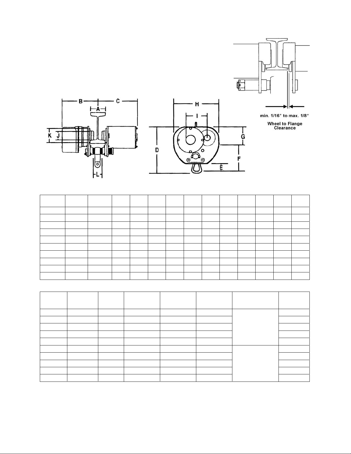
Specifications
Figure 1
Stock No. Model
262605 1/2ET-3C 3-5 9 1/8 10 10 2 6 1/2 3 1/2 9 11/16 4 1/2 2 3/4 3 11/16 1 5/8
262610 1ET-3C 3-5 9 1/8 10 10 2 6 1/2 3 1/2 9 11/16 4 1/2 2 3/4 3 11/16 1 5/8
262620 2ET-3C 4-6 9 3/4 10 5/8 11 1/2 2 43/64 7 43/64 4
262630 3ET-3C 4-6 10
262250 5ET-3C 5-7
272705 1/2ET-1C 3-5 9 1/8 10 10 2 6 1/2 3 1/2 9 11/1 6 4 1/2 2 3/4 3 11/16 1 5/8
272710 1ET-1C 3-5 9 1/8 10 10 2 6 1/2 3 1/2 9 11/16 4 1/2 2 3/4 3 11/16 1 5/8
272720 2ET-1C 4-6 9 3/4 10 5/8 11 1/2 2 43/64 7 43/64 4
272730 3ET-1C 4-6 10
272750 5ET-1C 5-7
A
(min.-max.)
10 11/16
10 11/16
B C
D E F G H I J K L
12 43/64
12 27/32
12 27/32
14 5/32 3 9 5/32 5 12 7/16 4 1/4 4 6 1 9/16
13 5/8 16 1/2 4 10 1/2 6 13 1/4 4 7/16 4 6 1/ 4 2 1/8
12 43/64
14 5/3 2 3 9 5/32 5 12 7/16 4 1/4 4 6 1 9/16
13 5/8 16 1/2 4 10 1/2 6 13 1/4 4 7/16 4 6 1/ 4 2 1/8
5 1/4 3 1/4 4 3/4 1 19/32
5 1/4 3 1/4 4 3/4 1 19/32
Stock No. Model
262605 1/2ET-3C 1/2 3-5 43.3 39.36
262610 1ET-3C 1 3-5 43.3 39.36 82
262620 2ET-3C 2 4-6 59 39.36 112
262630 3ET-3C 3 4-6 59 39.36 148
262250 5ET-3C 5 5-7 78.75 39.36 185
272705 1/2ET-1C 1/2 3-5 43.3 39.36
272710 1ET-1C 1 3-5 43.3 39.36 84
272720 2ET-1C 2 4-6 59 39.36 114
272730 3ET-1C 3 4-6 59 39.36 150
272750 5ET-1C 5 5-7 78.75 39.36 187
Capacity
(ton)
Beam Flange
Width
(in.)
Minimum
Radius Curve
(in.)
Travel Speed
(FPM)
Motor
3 Phase , 230/460V
(prewir ed 460V)
1 Phase , 115/230V
(prewir ed 230V)
Approximate
Net Weight
(lbs.)
82
84
The above specifications were current at the time this manual was publi shed, but bec ause of our policy of
continuous improvement, Walter M eier reserves the right to change specifications at any time and without
prior notice, wit hout incurring obligati ons.
5
Unpacking
Open shipping cont ainer and check f or shipping
damage. Report any damage immediately to
your distributor and shipping agent. Do not
discard any shi pping materi al until the Troll ey is
assembled and running properly.
Compare the c ontents of y our cont ainer wit h the
following parts list to make sure all parts are
intact. Missing par ts, if any, should be reported
to your distributor. Read the instruction manual
thoroughly for assembly, maintenance and
safety instructions.
Contents of the Shipping Containe r
1 Electric Trolley
1 Cord holder with c able tie
12 Phillips Pan Head Screws, M5x12
12 Lock Washers, 5mm
1 Owner's Manual
1 Warranty Card
Installation and Assembly
The ET-C Series trolley is designed to run on
standard “I” beam s, wide-fl anged “H” beams, or
curved track with a minimum radius shown in the
chart on page 5.
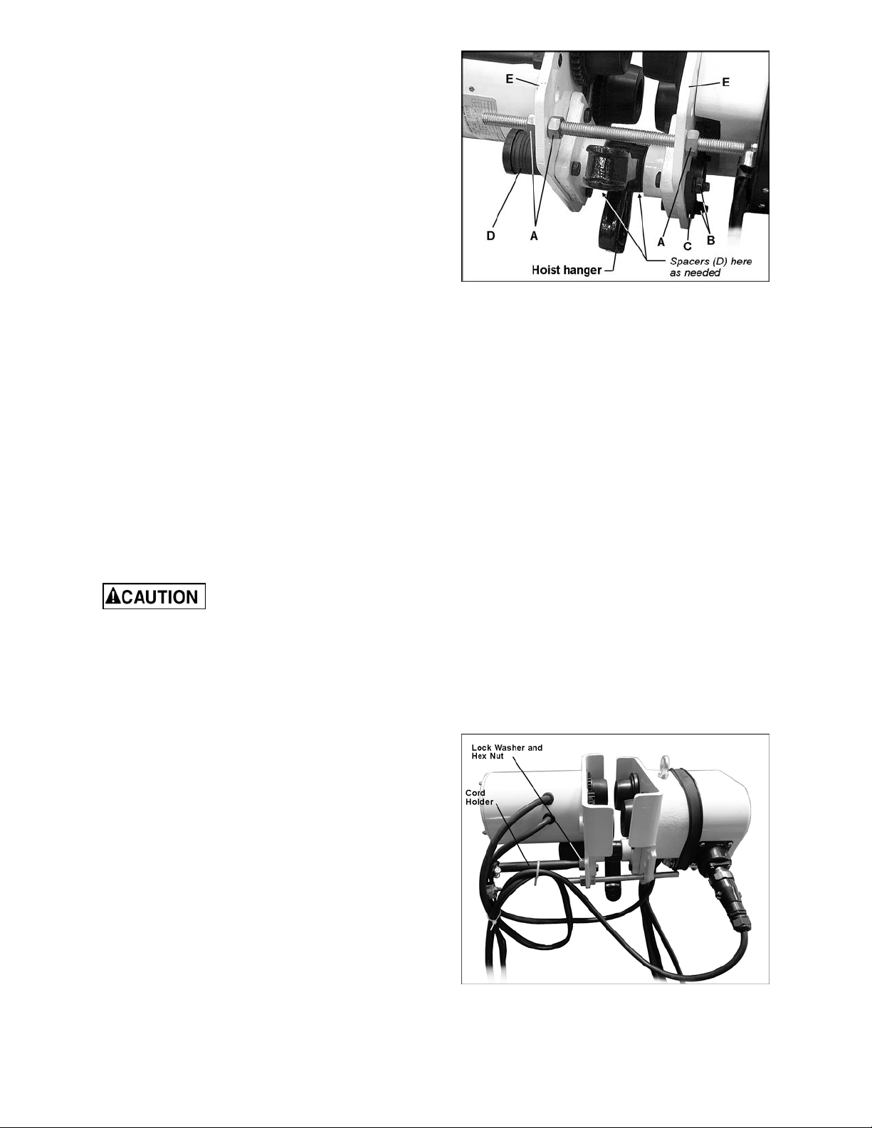
Figure 2
6. Re-install the plate (C) and two hex nut s (B),
and tighten the hex nut s.
7. Reinstall the adjusting screw and hex nuts
(A) and adjust to the proper width.
8. Double-check the wheel clearance on the
beam, and make further adjustments if
necessary.
Power and Pendant Cords
Mount Trolley to Beam
The trolley is heavy; use an
assistant o r a l ifting device to help stabilize it
while you assemble it to the beam.
1. Loosen the hex nuts (A, Figure 2) on the
adjusting screw, and remove the adjusting
screw.
2. Remove the two hex nuts (B, Fi gure 2) with
the plate (C, Figure 2) .
3. Slide out the suspension shaft with the
spacers (D, Figure 2) .
4. Assem ble the trolley to the beam. The trolley
must be installed on a beam with a mi nim um
clearance (wheels to flange) of 1/16” to a
maximum of 1/ 8” on each side of the beam
(see Figure 1, page 5). Position the side
plates (E, Figure 2) to achieve this
measurement on your beam .
5. Re-i nstall the suspen sion shaf t, while using
the spacers (D) to achieve the required
width. Spacers must be moved in sets of
two, placing equal num ber s on both si des of
the hoist hanger to maintain the centerline of
the trolley. Place any extra spacers on the
outside of the shaft , as shown in Fi gur e 2.
NOTE: A pendant c ord is not supplied wit h the
trolley, and must be pur c hased sep ar ately. If you
need to change the v oltage requir ements on the
trolley, it is more convenient to do that before
installing a pendant cord. See “Voltage
Conversion” on page 9.
1. Thread the cord holder (Figure 3) into the
hole on the motor side plat e and tighten the
jam nut and lock washer. The ring on the
cord holder should be posi t ioned vertically.
Figure 3
6
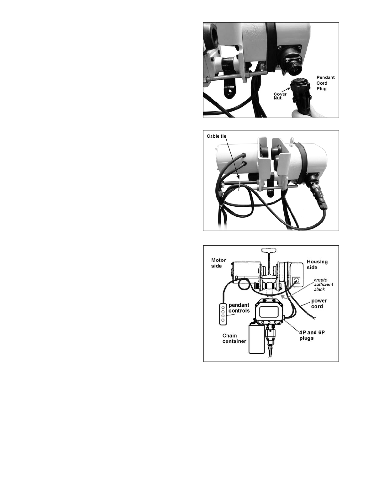
2. Insert the mal e plug of the pendant cord i nt o
the socket on the trolley. See Figure 4.
Secure the connection by tightening the
cover nut with your fi nger s.
3. Att ach the pendant cord to the cord holder.
The cord m ust be secured to the cord holder
in a way that relieves strain on the
connections. O ne method of doi ng this is to
form a loop in the pendant cord and place
the cable tie as shown in Figure 5. Do not
tighten the cable tie yet.
4. Create sufficient slack in the pendant cord
where it passe s under t he I-be am (Figur e 6)
so that the cord will not rub against the
beam.
5. Ti ghten the cable tie to secure the pendant
cord to the cord holder.
Mounting Your Hoist
This troll ey has been designed to work with the
JET C-Seri es Hoist. They can be con nected so
that one pendant cord and power cord will
operate both trolley and hoist. Make sure the
hoist has been set to the same voltage
specifications as the trolley.
Make connecti ons from the t rolley to your hoist
as follows:
1. Hang the hoist on the trolley hanger, using
hook or lug mount. (See page 8 for
instructions on installing the optional lug
mount.) The hoist should be positioned so
that the el ectrical socket on t he trolley i s on
the same side as the sockets on the hoist,
as shown in Figure 6.
Figure 4
Figure 5
2. Remove the power cord and pendant cord
from the hoist.
3. Connect the two 4P and 7P plugs of the
trolley cords into their appropriate sockets
on the hoist.
Figure 6
7
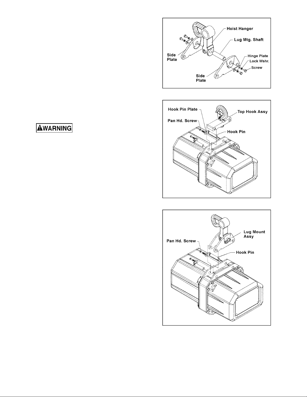
Installing Lug Mount Accessory
1. A ssemble the side pl ates, hoist hanger and
lug mounting shaft, as shown in Figure 7.
2. Install the hinge plates, lock washers and
hex cap screw to secure the assembly.
3. On the electric hoist, remove the two
screws, hook pin plate, hook pin, etc.
(Figure 8)
4. Remove the top hook assembly from the
hoist, and replace it with the lug mount
accessory as shown in Figure 9. Re-install
the hook pins, ho ok pin plates, screws and
washers. Firmly tighten the screws.
Electrical Instructions
Electrical connections must
be made by a qualified electrician in
compliance with all relevant codes. This
machine must be properly grounded to help
prevent electrical shock and possible fatal
injury.
Figure 7
Grounding
In the event of a malfunction or breakdown,
grounding prov ides a path of least resistance f or
electric current to reduce the risk of electric
shock.
This machine’s power cord must be fitted with
an appropriate UL/ CSA listed plug, or it can be
“hard-wired” directly to a control panel. If hardwired, make sure a disconnect is available for
the operator.
If a plug is install ed, it must hav e an equipmentgrounding conductor and a grounding prong.
The plug must be pl ugged i nto a matchi ng outl et
that is properly installed and grounded in
accordance wit h all local codes and ordinanc es.
Do not modify the plug.
Improper connection of the equipmentgrounding conductor can result in a risk of
electric shock. The conductor with insulation
having an outer surface that is green with or
without yellow stripes is the equipmentgrounding connector . If repair or replacement of
the electric cord or plug is necessary, do not
connect the equi pment-grounding conductor to a
live terminal.
Figure 8
Figure 9
8

Check with a qualified electrician or service
personnel if the grounding instructions are not
completely understood, or if in doubt as to
whether the tool is properly grounded.
Repair or replace damaged or worn cord
immediately.
Voltage Conversion
The single phase models (ET-1C) are
designed for 115 volt or 230 volt operation. They
are pre-wired for 230 volt. The three phase
models (ET-3C) are designed for 230 volt or
460 volt operati on. T hey ar e pre-wir ed for 460V.
To switch voltage:
1. Disconnect trolley from power supply, and
disconnect the pendant c or d from the trolley.
2. Remove the two screws and lock washers
on the underside of the hou sing (see F igure
10) and slide the prot ective band out of t he
way. Remove the housing.
3. Carefully pull the plug out of the current
socket and insert i t into the new socket (see
Figure 10). Mak e sure the notch on the plug
fully engages the socket .
4. Re-install the housing, re-position the
protective band, and insert the screws and
lock washers. Ti ghten the screws securely.
Test the motion of t he hoist also:
2. With no load on the load hook , press the UP
button ver y briefly and observ e hoist action.
The hook should m ove upward. (T wo speed
models have a two-position UP button.
Press the button onl y par t way to operat e l if t
motor at slow speed, press fully to operate
at high speed.)
3. If no motion occurs when the UP button is
pressed and the hoist is connected to a
three phase power suppl y, t he power suppl y
wires are incorrectly positioned.
4. S witch any two of t he three supply wires at
the power sour c e. Do not attempt to rewire
the hoist/trolley circuit or pendant
controls for this problem. Use the same
safety precautions when reversing t wo of t he
supply wires as was used when the wires
were originally c onnected.
5. Re- connect power and test hoist and troll ey
movement again without load. Run hoist to
the complete lifting height to ensure limit
switches are operating properly.
Refer to your hoist manual for more detailed
instructions on operation and testing of the hoist.
Extension Cords
If an extension cord is nece s sary, make sure the
cord rating is suit able f or t he amperage li sted on
the trolley ’s motor pl ate. An undersize cord wil l
cause a drop in li ne voltage result ing in loss of
power and overheating.
Figure 10
Inspecting Trolley Motion
1. Before closing the cir c uit breaker and testi ng
the trolley, check that wiring has been
complete. If the trolley cannot be observed
when the circ uit breaker i s closed, station an
observer wit hin sight of the troll ey to report
any movement when power i s appl i ed to t he
trolley. Be prepared to disconnect power if
trolley motor starts when the power is
applied. T he troll ey must remai n motionless
when power is appl ied. Find and c orrect any
problems bef or e continuing.
The chart in Figure 11 shows the correct size
cord to use based on cord length and motor
plate amp rating. If in doubt, use the next
heavier gauge. The smaller the gauge number,
the heavier the cord.
Recommended Gauges (AWG) of Extension Cords
Extension Cord Length *
Amps
< 5 16 16 16 14 12 12
5 to 8 16 16 14 12 10 NR
8 to 12 14 14 12 10 NR NR
12 to 15 12 12 10 10 NR NR
15 to 20 10 10 10 NR NR NR
21 to 30 10 NR NR NR NR NR
*based on limit ing th e lin e volt ag e drop to 5V at 15 0% of the
rated amp eres.
NR: Not Recommended.
25
feet
50
feet
75
feet
100
feet
150
feet
200
feet
Figure 11
9

Control Pendant Accessories
Pendants with 4 buttons are for Lifting and Lowering, and 2-di r ec tion Trolley travel.
Pendants with 6 buttons are for Lift ing and Lowering, 2-direc tion Trolley travel, and 2- direction Saddle
travel. (NOT E: S addle travel requires further accessories not provided with this trolley.)
On dual speed controls, par tially press the button f or low speed, fully press the button f or high speed.
142410 Dual Speed, 4 Button Control Pendant with 10’ Lift.
142415 Dual Speed, 4 Button Control Pendant with 15’ Lift.
142420 Dual Speed, 4 Button Control Pendant with 20’ Lift.
142610 Dual Speed, 6 Button Control Pendant with 10’ Lift.
142615 Dual Speed, 6 Button Control Pendant with 15’ Lift.
142620 Dual Speed, 6 Button Control Pendant with 20’ Lift.
152410 Single Speed, 4 Button Control Pendant with 10’ Lift.
152415 Single Speed, 4 Button Control Pendant with 15’ Lift.
152420 Single Speed, 4 Button Control Pendant with 20’ Lift.
152610 Single Speed, 6 Button Control Pendant with 10’ Lift.
152615 Single Speed, 6 Button Control Pendant with 15’ Lift.
152620 Single Speed, 6 Button Control Pendant with 20’ Lift.
162410 Single Speed, 4 Button Control Pendant f or VFD Hoists wit h 10’ Lift.
162415 Single Speed, 4 Button Control Pendant f or VFD Hoists wit h 15’ Lift.
162420 Single Speed, 4 Button Control Pendant f or VFD Hoists wit h 20’ Lift.
162430 Single Speed, 4 Button Control Pendant f or VFD Hoists wit h 30’ Lift.
10

Troubleshooting
Trouble Probable Cause Remedy
Trolley will not
operate, or operat es
intermittently.
Trolley drift s
excessively after
stopping.
Hoist moves in wrong
direction.
Check trolley connec t ions to power
source. Make sure power source
No incoming power, or low voltage.
Fuse blown or circuit breaker tripped. Replace fuse/re-set circuit breaker.
Thermal ov erl oad pr otector has
tripped; motor overheated.
Conductors in pendant cor d
damaged.
Motor damaged.
Grease or oil on the brake lining.
Brake pad is worn or damaged. Replace brake pad.
Two of the three power supply wires
are switched.
matches specifications on trolley
name plate. If low voltage, have
certified electrician check incoming
power.
See “Motor over heats” below.
Check for continuity in each
conductor. If faulty, replace entire
pendant cord.
Have motor inspected and repaired/
replaced by a qualified service
technician.
Open the trolley, disassemble the
brake and clean the lining.
Switch any two of the thr ee suppl y
wires.
Excessive load or too frequent use.
Motor overheat s.
Brake is draggi ng.
Operate within r at ed load and
according to duty cycle rating.
Have brake repaired or r eplac ed by a
qualified service technician.
Replacement Parts
Replacement par ts are li sted on the f ollowing page s. To order par ts or reach our serv i ce departm ent, call
1-800-274-6848, Monday through Friday (see our website for business hours, www.waltermeier.com).
Having the Model Number and Serial Number of your mac hine available when you call will allow us to
serve you quickly and accurately.
11

ET-C Series Trol ley
Y
L
N
O
E
S
A
H
P
E
E
R
H
T
D
N
A
E
L
G
N
I
S
N
I
T
E
5
&
3
R
O
F
12

Parts List: ET-C Series Trolley
Index No. P art No. Description Size Qty
1 ................ 1/2ET-3 C-1 ...... N ame Plate (1/2T, three phase) ............................ ...................................... 1
.................. 1ET-3C- 1 ......... Name Plate (1T, three phase) ............................... ...................................... 1
.................. 2ET-3C- 1 ......... Name Plate (2T, three phase) ............................... ...................................... 1
.................. 3ET-3C- 1 ......... Name Plate (3T, three phase) ............................... ...................................... 1
.................. 5ET-3C- 1 ......... Name Plate (5T, three phase) ............................... ...................................... 1
.................. 1/2ET-1C -1 ...... Name Plate (1/2T, single phase) ........................... ...................................... 1
.................. 1ET-1C- 1 ......... Name Plate (1T, single phase) .............................. ...................................... 1
.................. 2ET-1C- 1 ......... Name Plate (2T, single phase) .............................. ...................................... 1
.................. 3ET-1C- 1 ......... Name Plate (3T, single phase) .............................. ...................................... 1
.................. 5ET-1C- 1 ......... Name Plate (5T, single phase) .............................. ...................................... 1
2 ................ 1ET-3C -2 ......... Housing (1/2T,1T,2 T,3T,5 T) .................................. ...................................... 1
3 ................ 1ET-3C -3 ......... Socket Head Cap Screw (1/2T,1T,2T,3T,5T) ......... M8x70 ........................... 2
4 ................ 1ET-3C -4 ......... Lock Wash er (1/2T,1T,2 T,3T,5T) .......................... 8mm .............................. 7
5 ................ 1ET-3C -5 ......... Electrical Board (1/2T,1T ,2T, three phase) ............ ...................................... 1
.................. 3ET-3C- 5 ......... Electrical Board (3T, 5T, three phase) ................... ...................................... 1
.................. 1ET-1C- 5 ......... Electrical Board (1/2T,1T ,2T, single phase) ........... ...................................... 1
.................. 3ET-1C- 5 ......... Electrical Board (3T,5T, single phase) ................... ...................................... 1
6 ................ 1ET-3C -6 ......... Protective Band (1/2T,1T,2T,3T, 5T) ...................... ...................................... 1
7 ................ 1ET-3C -7 ......... Eye Bolt (1/2T,1T,2 T,3T ,5T).................................. M8x16 ........................... 2
8 ................ 1ET-3C -8 ......... Balance Spacer (1/2T,1T,2 T) ................................ ...................................... 1
.................. 3ET-3C- 8 ......... Balance Spacer (3T,5T) ........................................ ...................................... 1
9 ................ 1ET-3C-9 ......... Plain Side Plate Assembly (1/2T,1T) ..................... ...................................... 1
.................. 2ET-3C-9 ......... Plain Side Plate Assembly (2T) ............................. ...................................... 1
.................. 3ET-3C-9 ......... Plain Side Plate Assembly (3T) ............................. ...................................... 1
.................. 5ET-3C-9 ......... Plain Side Plate Assembly (5T) ............................. ...................................... 1
10 .............. 1ET-3C-10 ....... Plain Wheel (1/2T,1 T) ........................................... ...................................... 2
.................. 2ET-3C- 10 ....... Plain Wheel (2T) ................................................... ...................................... 2
.................. 3ET-3C- 10 ....... Plain Wheel (3T) ................................................... ...................................... 2
.................. 5ET-3C- 10 ....... Plain Wheel (5T) ................................................... ...................................... 2
11 .............. 1ET-3C-11 ....... Circlip for shaft (1/2T,1 T) ...................................... Ø17mm ......................... 4
.................. 2ET-3C- 11 ....... Circlip for shaft (2T) .............................................. Ø 25mm ............. ........... 4
.................. 3ET-3C- 11 ....... Circlip for shaft (3T) .............................................. Ø 30mm ............. ........... 4
.................. 5ET-3C- 11 ....... Circlip for shaft (5T) .............................................. Ø 35mm ............. ........... 4
12 .............. 1ET-3C-12 ....... Washer (1/2T,1T) .................................................. ...................................... 4
.................. 2ET-3C- 12 ....... Washe r (2T).......................................................... ...................................... 4
13 .............. 1ET-3C-13 ....... Geared Wheel (1/2T, 1T) ....................................... ...................................... 2
.................. 2ET-3C- 13 ....... Geared Wheel (2T) ............................................... ...................................... 2
.................. 3ET-3C- 13 ....... Geared Wheel (3T) ............................................... ...................................... 2
.................. 5ET-3C- 13 ....... Geared Wheel (5T) ............................................... ...................................... 2
14 .............. 1ET-3C-14 ....... Fifth Gear (1/2T,1 T,2 T) ......................................... ...................................... 1
.................. 3ET-3C- 14 ....... Fifth Gear (3T,5T) ................................................. ...................................... 1
15 .............. 1ET-3C-15 ....... Roller Bearing (1/2T,1T) ........................................ 6203-2Z ......................... 4
.................. 2ET-3C- 15 ....... Roller Bearing (2T) ............................................... 6205-2Z ......................... 4
.................. 3ET-3C- 15 ....... Roller Bearing (3T) ............................................... 6206-2Z ......................... 4
.................. 5ET-3C- 15 ....... Roller Bearing (5T) ............................................... 6207-2Z ......................... 4
16 .............. 1ET-3C-16 ....... Circlip for hole (1/2T,1 T) ....................................... 40mm ............................ 4
.................. 2ET-3C- 16 ....... Circlip for hole (2T) ............................................... 52mm ............... ............. 4
.................. 3ET-3C- 16 ....... Circlip for hole (3T) ............................................... 62mm ............... ............. 4
.................. 5ET-3C- 16 ....... Circlip for hole (5T) ............................................... 72mm ............... ............. 4
17 .............. 1ET-3C-17 ....... Gear Side Plate Assembly (1/2T,1T) ..................... ...................................... 1
.................. 2ET-3C-17 ....... Gear Side Plate Assembly (2T) ............................. ...................................... 1
.................. 3ET-3C-17 ....... Gear Side Plate Assembly (3T) ............................. ...................................... 1
.................. 5ET-3C-17 ....... Gear Side Plate Assembly (5T) ............................. ...................................... 1
18 .............. 1ET-3C-18 ....... Roller Bearing (1/2T,1T,2 T)................................... 6004-2ZN ...................... 1
.................. 3ET-3C- 18 ....... Roller Bearing (3T,5T) .......................................... 6205-2ZN ...................... 1
19 .............. 3ET-3C-19 ....... Safety Block (3T) .................................................. ...................................... 4
.................. 5ET-3C- 19 ....... Safety Block (5T) .................................................. ...................................... 4
13

Index No. P art No. Description Size Qty
20 .............. 1ET-3C-20 ....... Roller Bearing w/Snap Ring (1/2T,1T,2T) .............. 42mm ............................ 1
.................. 3ET-3C- 20 ....... Roller Bearing w/Snap Ring (3T,5T) ...................... 52mm ............................ 1
21 .............. 1ET-3C-21 ....... Third Gear (1/2T ,1T,2 T) ........................................ ...................................... 1
22 .............. 1ET-3C-22 ....... Fourth Gear (1/2T,1T,2T) ...................................... ...................................... 1
23 .............. 1ET-3C-23 ....... Second Gear (1/2T,1T, 2T) .................................... ...................................... 1
.................. 3ET-3C- 23 ....... Second Gear (3T, 5T) ............................................ ...................................... 1
24 .............. 1ET-3C-24 ....... Roller Bearing (1/2T,1T,2 T)................................... 6003-2Z ......................... 4
.................. 3ET-3C- 24 ....... Roller Bearing (3T,5T) .......................................... 6004-2Z ......................... 4
25 .............. 3ET-3C-25 ....... Gear Case Gasket (3T,5T) .................................... ...................................... 1
26 .............. 3ET-3C-26 ....... Gear Cas e (3T,5T) ................................................ ...................................... 1
27 .............. 1ET-3C-27 ....... Flange (1/ 2T, 1T, 2T) .............................................. ...................................... 1
28 .............. 1ET-3C-28 ....... Lock Washer (1/2T,1T,2 T,3T,5T) .......................... 8mm .............................. 4
29 .............. 1ET-3C-29 ....... Hex Nut (1/2T,1T,2 T) ............................................ M8 ................................. 3
30 .............. TS-1504051 ..... Socket Head Cap Screw (3T,5T) ........................... M8x25 ........................... 4
31 .............. 1ET-3C-31 ....... Motor Case Assembly (1/2T,1T,2T)....................... ...................................... 1
.................. 3ET-3C-31 ....... Motor Case Assembly (3T,5T) .............................. ...................................... 1
.................. 1ET-1C-31 ....... Motor Case Assembly (1/2T,2T,2T,single phase) .. ...................................... 1
.................. 3ET-1C-31 ....... Motor Case Assembly (3T,5T, single phas e) ......... ...................................... 1
32 .............. 1ET-3C-32 ....... Rotor Assembly (1/2T,1T,2 T) ................................ ...................................... 1
.................. 3ET-3C- 32 ....... Rotor Ass embly (3T,5T) ........................................ ...................................... 1
.................. 1ET-1C- 32 ....... Rotor Ass embly (1/2T,1T,2 T, single phase) ........... ...................................... 1
.................. 3ET-1C- 32 ....... Rotor Ass embly (3T,5T, single phase)................... ...................................... 1
33 .............. 1ET-3C-33 ....... Brake Spring (1/2T,1T,2 T) .................................... ...................................... 1
.................. 3ET-3C- 33 ....... Brake Spring (3T,5T) ............................................ ...................................... 1
34 .............. 1ET-3C-34 ....... Motor Stay Bolt (1/2T,1T,2T) ................................. ...................................... 4
.................. 3ET-3C-34 ....... Motor Stay Bolt (3T,5T) ......................................... ...................................... 4
35 .............. 1ET-3C-35 ....... Friction Pad Assembly (1/2T,1T,2T) ...................... ...................................... 1
.................. 3ET-3C-35 ....... Friction Pad Assembly (3T,5T) .............................. ...................................... 1
36 .............. 1ET-3C-36 ....... Motor End Plate (1/2T,1T,2T,3T,5T) ...................... ...................................... 1
37 .............. 1ET-3C-37 ....... Lock Washer (1/2T,1T,2 T,3T,5T) .......................... 5mm .............................. 4
38 .............. 1ET-3C-38 ....... Acorn Nut (1/2T,1 T,2T,3 T,5T) ............................... M5 ................................. 4
40 .............. 1ET-3C-40 ....... Lock Washer (1/2T,1T,2 T,3T,5T) .......................... 8mm .............................. 1
41 .............. 1ET-3C-41 ....... Hex Nut (1/2T,1 T,2T,3T ,5T) .................................. M8 ................................. 1
42 .............. 1ET-3C-42 ....... Cable Press Plate (1/2T,1T,2T,3T,5T) ................... ...................................... 1
43 .............. 1ET-3C-43 ....... Phillips Pan Head Screw (1/2T,1T,2T,3T,5T) ........ M5x10 ........................... 2
44 .............. 1ET-3C-44 ....... Plate Key (1/2T,1 T) ............................................... ...................................... 1
.................. 2ET-3C- 44 ....... Plate Key (2T) ....................................................... ...................................... 1
.................. 3ET-3C- 44 ....... Plate Key (3T)
.................. 5ET-3C- 44 ....... Plate Key (5T) ....................................................... ...................................... 1
45 .............. 1ET-3C-45 ....... Hoist Hanger (1/ 2T,1T) ......................................... ...................................... 1
.................. 2ET-3C- 45 ....... Hoist Hanger (2T) ................................................. ...................................... 1
.................. 3ET-3C- 45 ....... Hoist Hanger (3T) ................................................. ...................................... 1
.................. 5ET-3C- 45 ....... Hoist Hanger (5T) ................................................. ...................................... 1
46 .............. 1ET-3C-46 ....... Hex Cap Screw (1/2T,1T) ..................................... M8x40 ........................... 8
.................. 2ET-3C-4 6 ....... Hex Cap Screw (2T) ............................................. M10x45 ......................... 8
.................. 3ET-3C-4 6 ....... Hex Cap Screw (3T) ............................................. M10x50 ......................... 8
.................. 5ET-3C-4 6 ....... Hex Cap Screw (5T) ............................................. M14x65 ......................... 8
47 .............. 1ET-3C-47 ....... Lock Washer (1/2T,1T) ......................................... 8mm .............................. 8
.................. 2ET-3C- 47 ....... Lock Washe r (2T) ................................................. 10mm ............................ 8
.................. 3ET-3C- 47 ....... Lock Washe r (3T) ................................................. 10mm ............................ 8
.................. 5ET-3C- 47 ....... Lock Washe r (5T) ................................................. 14mm ............................ 8
48 .............. 1ET-3C-48 ....... Hex Nut (1/2T,1T) ................................................. M8 ................................. 8
.................. 2ET-3C- 48 ....... Hex Nut (2T) ......................................................... M10 ............................... 8
.................. 3ET-3C- 48 ....... Hex Nut (3T) ......................................................... M10 ............................... 8
.................. 5ET-3C- 48 ....... Hex Nut (5T) ......................................................... M14 ............................... 8
49 .............. 1ET-3C-49 ....... Cord Holder (1/2T,1T,2T ,3T,5 T) ............................ ...................................... 1
....................................................... ...................................... 1
14

Index No. Part No. Description Size Qty
50 .............. 1ET-3C-50 ....... Spacer (1/2T,1T) ................................................... .................................... 16
.................. 2ET-3C- 50 ....... Spacer (2T) .......................................................... .................................... 16
.................. 3ET-3C- 50 ....... Spacer (3T) .......................................................... .................................... 16
.................. 5ET-3C- 50 ....... Spacer (5T) .......................................................... .................................... 16
51 .............. 1ET-3C-51 ....... Suspens ion Shaft (1/2T,1 T) .................................. ...................................... 1
.................. 2ET-3C- 51 ....... Suspension Shaft (2T) .......................................... ...................................... 1
.................. 3ET-3C- 51 ....... Suspension Shaft (3T) .......................................... ...................................... 1
.................. 5ET-3C- 51 ....... Suspension Shaft (5T) .......................................... ...................................... 1
52 .............. 1ET-3C-52A .... Male Plug for 7-Pin (1/2T,1T,2T,3T,5T) ................. YD28K7TQPGB.5 .......... 1
53 .............. 1ET-3C-53A .... Male Plug for 4-Pin (1/2T,1T,2T,3T,5T) ................. YD24K4TQPGB.5 .......... 1
54 .............. 1ET-3C-54 ....... Coupling Cable P (1/2T,1T,2T,3T,5T) ................... 1M ................................. 1
55 .............. 1ET-3C-55 ....... Coupling Cable C (1/2T,1T,2T,3T,5T) ................... 1M ................................. 1
56 .............. 1ET-3C-56 ....... Power Cord (1/2T,1T,2T,3 T,5T ) ............................ 2M ................................. 1
58 .............. 1ET-3C-58 ....... Hex Nut (1/2T,1T,2 T) ............................................ M12 ............................... 3
.................. 3ET-3C- 58 ....... Hex Nut (3T,5T) .................................................... M16 ............................... 3
59 .............. 1ET-3C-59 ....... Threaded Shaft (1/2T ,1T) ...................................... ...................................... 1
.................. 2ET-3C- 59 ....... Threaded Shaft ( 2T).............................................. ...................................... 1
.................. 3ET-3C- 59 ....... Threaded Shaft ( 3T).............................................. ...................................... 1
.................. 5ET-3C- 59 ....... Threaded Shaft ( 5T).............................................. ...................................... 1
60 .............. 1ET-3C-60 ....... Seal Gasket (1/2T,1T,2T,3 T,5T ) ........................... ...................................... 1
61 .............. TS-1533042 ..... Phillips Pan Head Machine Screw (1/2T,1T,2T,3T,5T)…M5X12 ................... 4
62 .............. 1ET-3C-52 ....... Connector Case (1/2T,1T,2T,3T, 5T) ..................... ...................................... 1
63 .............. 1ET-3C-63 ....... Female Plug (1/2T,1T,2T,3 T,5 T) ........................... YD28J 15Z ..................... 1
64 .............. 1ET-3C-64 ....... Phillips Pan Head Machine Screw (1/2T,1T,2T,3T,5T)…M3X14 ................... 4
15

Parts List: Lug Mount Assembly (Optional) for SS-3C,SS-1C and DS-3C Hoists
For Electric Hoi st s in 1/2T, 1T and 2T
Index No. P art No. Description Size Qty
................. 1/2SS-3C-LMA .........Lug Mount Assembly (1/2T) ............................ ........................................
................. 1SS-3C-LMA ............Lug Mount Assembly (1T) ............................... ........................................
................. 2SS-3C-LMA ............Lug Mount Assembly (2T) ............................... ........................................
1 ............... 1/2SS-3C-116 ..........Side Plate L.H. (1/2T) ..................................... ...................................... 1
................. 1SS-3C-116 .............Side Plate L.H. (1T) ........................................ ...................................... 1
................. 2SS-3C-116 .............Side Plate L.H. (2T) ........................................ ...................................... 1
2 ............... 1ET-3C-45 ...............Ho ist Hanger (1/2T,1T)* .................................. ...................................... 1
................. 2ET-3C- 45 ...............Hoist Hanger (2T) * .......................................... ...................................... 1
3 ............... 1/2SS-3C-118 ..........Lug Mounting Shaft (1/ 2T, 1T) ......................... ...................................... 1
................. 2SS-3C-118 .............Lug Mounting Shaft (2T) ................................. ...................................... 1
4 ............... 1/2SS-3C-119 ..........Side Plate R.H. (1/2T) ..................................... ...................................... 1
................. 1SS-3C-119 .............Side Plate R.H. (1T) ....................................... ...................................... 1
................. 2SS-3C-119 .............Side Plate R.H. (2T) ....................................... ...................................... 1
5 ............... 3SS-3C-061 .............Hinge Plate ..................................................... ...................................... 2
6 ............... 1/2SS-3C-012 ..........Lock Washer .................................................. 6mm .............................. 4
7 ............... 1/2SS-3C-120 ..........Hex Head Cap Screw ..................................... M6x10 ........................... 4
For Electric Hoi st s in 3T and 5T
Index No. P art No. Description Size Qty
................. 3SS-3C-LMA ............Lug Mount Assembly (3T) ............................... ........................................
................. 5SS-3C-LMA ............Lug Mount Assembly (5T) ............................... ........................................
1 ............... 3SS-3C-116 .............Side Plate (3T) ............................................... ...................................... 2
................. 5SS-3C-116 .............Side Plate (5T) ............................................... ...................................... 2
2 ............... 3ET-3C-45 ...............Ho ist Hanger (3T)* .......................................... ...................................... 1
................. 5ET-3C- 45 ...............Hoist Hanger (5T) * .......................................... ...................................... 1
3 ............... 2SS-3C-118 .............Lug Mount ing Shaft (3T) ................................. ...................................... 1
................. 5SS-3C-118 .............Lug Mounting Shaft (5T) ................................. ...................................... 1
5 ............... 3SS-3C-061 .............Hinge Plate ..................................................... ...................................... 2
6 ............... 1/2SS-3C-012 ..........Lock Washer .................................................. 6mm .............................. 4
7 ............... 3SS-3C-120 .............Hex Head Cap Screw ..................................... M6x12 ........................... 4
* Hoist Hanger comes pre-assembled to the electri c tr olley .
16

Electrical Components
17

Parts List: Electrical Components
Index No. P art No. Description Size Qty
501 ........... 1ET-3C-501 .............Electrical Component Board (3Ph) ......................................................... 1
................. 1ET-1C- 501 .............Electrical Component Board (1/2T,1T, 2T: 1Ph) ..................................... 1
................. 3ET-1C- 501 .............Electrical Component Board (3T,5T: 1Ph) .............................................. 1
502 ........... 1ET-3C-502 .............Transformer (3Ph) ..............................................(460/230)/24V............. 1
................. 1ET-1C- 502 .............Transformer (1Ph) ..............................................(230/115)/24V............. 1
503 ........... 1ET-1C-503 .............Capacitor (1/2T,1T, 2T: 1P h) ...............................65µ F........................... 1
................. 3ET-1C- 503 .............Capacitor (3T,5T: 1Ph) .......................................120µF ......................... 1
504 ........... 1ET-1C-504 .............Capacitor (1/2T,1T, 2T: 1P h) ...............................16µ F........................... 1
................. 3ET-1C- 504 .............Capacitor (3T,5T: 1Ph) .......................................30µF........................... 1
505 ........... TS-1541001 .............Lock Nut (1Ph) ...................................................M4 .............................. 2
506 ........... 1ET-1C-506 .............Retainer Pin (1Ph) ................................................................................. 2
507 ........... 1ET-1C-507 .............Capacitor Holder (1/2T, 1T, 2T: 1P h) ....................................................... 1
508 ........... TS-1501061 .............Socket Head Cap Screw (1Ph) ..........................M4x20 ........................ 2
509 ........... 1ET-1C-509 .............Capacitor Holder (1/2T, 1T, 2T: 1P h) ....................................................... 1
................. 3ET-1C- 509 .............Capacitor Holder (3T,5T: 1Ph) ............................................................... 2
510 ........... TS-1541001 .............Lock Nut (1Ph) ...................................................M4 .............................. 2
513 ........... TS-1532032 .............Pan Head Screw (3Ph) .......................................M4x10 ........................ 5
................. TS-1532032 .............Pan Head Screw (1Ph) .......................................M4x10 ........................ 7
514 ........... TS-2361041 .............Lock Was h e r (3P h ) .............................................M4 .............................. 7
................. TS-2361041 .............Lock Was h e r (1P h ) .............................................M4 .............................. 9
515 ........... TS-1550021 .............Flat Washer (3Ph) ..............................................M4 .............................. 5
................. TS-1550021 .............Flat Washer (1Ph) ..............................................M4 .............................. 7
516 ........... 1ET-3C-516A
517 ........... 1ET-1C-517 .............Contactor Holder (1Ph) .......................................................................... 1
518 ........... TS-1532032 .............Pan Head Screw ................................................M4x10 ........................ 2
519 ........... 1ET-3C-519 .............Terminal Board ...................................................................................... 1
...........Contac to r ...........................................................V B6 - 3 0 -0 1 .................. 1
18

Electrical Connections – Single Phase Only
19

Electrical Connections – 3 Phase Only
20

Electrical Connections – Control Pendants
4-PUSHBUTTON WIRING DIAGRAM
FOR SINGLE SPEED HOISTS
4-PUSHBUTTON WIRING DIAGRAM
FOR DUAL SPEED HOISTS
6-PUSHBUTTON WIRING DIAGRAM
FOR SINGLE SPEED HOISTS
6-PUSHBUTTON WIRING DIAGRAM
FOR DUAL SPEED HOISTS
4-PUSHBUTTON WIRING DIAGRAM
FOR VFD HOISTS
21

NOTES
22

NOTES
23

WALTER M EIE R (Manufa cturing) Inc.
427 New Sanford Road
LaVergne, Tennessee 37086
Phone: 800-274-6848
www.waltermeier.com
24
 Loading...