

Page 1

This .pdf document is bookmarked
Operating Instructions and Parts Manual
ET-C Series Electric Trolley
JET
427 New Sanford Road
LaVergne, Tennessee 37086 Part No. M-262605
Ph.: 800-274-6848 Revision E1 06/2017
www.jettools.com Copyright © 2017 JET
Page 2

1.0 Warranty and Service
JET warrants every product it sells against manufacturers’ defects. If one of our tools needs service or repair, please
contact Technical Service by calling 1-800-274-6846, 8AM to 5PM CST, Monday through Friday.
Warranty Period
The general warranty lasts for the time period specified in the literature included with your product or on the official
JET branded website.
• JET products carry a limited warranty which varies in duration based upon the product. (See chart below)
• Accessories carry a limited warranty of one year from the date of receipt.
• Consumable items are defined as expendable parts or accessories expected to become inoperable within a
reasonable amount of use and are covered by a 90 day limited warranty against manufacturer’s defects.
Who is Covered
This warranty covers only the initial purchaser of the product from the date of delivery.
What is Covered
This warranty covers any defects in workmanship or materials subject to the limitations stated below. This warranty
does not cover failures due directly or indirectly to misuse, abuse, negligence or accidents, normal wear-and-tear,
improper repair, alterations or lack of maintenance. JET woodworking machinery is designed to be used with Wood.
Use of these machines in the processing of metal, plastics, or other materials outside recommended guidelines may
void the warranty. The exceptions are acrylics and other natural items that are made specifically for wood turning.
Warranty Limitations
Woodworking products with a Five Year Warranty that are used for commercial or industrial purposes default to a
Two Year Warranty. Please contact Technical Service at 1-800-274-6846 for further clarification.
How to Get Technical Support
Please contact Technical Service by calling 1-800-274-6846. Please note that you will be asked to provide proof
of initial purchase when calling. If a product requires further inspection, the Technical Service representative will
explain and assist with any additional action needed. JET has Authorized Service Centers located throughout the
United States. For the name of an Authorized Service Center in your area call 1-800-274-6846 or use the Service
Center Locator on the JET website.
More Information
JET is constantly adding new products. For complete, up-to-date product information, check with your local distributor
or visit the JET website.
How State Law Applies
This warranty gives you specific legal rights, subject to applicable state law.
Limitations on This Warranty
JET LIMITS ALL IMPLIED WARRANTIES TO THE PERIOD OF THE LIMITED WARRANTY FOR EACH PRODUCT.
EXCEPT AS STATED HEREIN, ANY IMPLIED WARRANTIES OF MERCHANTABILITY AND FITNESS FOR A
PARTICULAR PURPOSE ARE EXCLUDED. SOME STATES DO NOT ALLOW LIMITATIONS ON HOW LONG AN
IMPLIED WARRANTY LASTS, SO THE ABOVE LIMITATION MAY NOT APPLY TO YOU.
JET SHALL IN NO EVENT BE LIABLE FOR DEATH, INJURIES TO PERSONS OR PROPERTY, OR FOR
INCIDENTAL, CONTINGENT, SPECIAL, OR CONSEQUENTIAL DAMAGES ARISING FROM THE USE OF OUR
PRODUCTS. SOME STATES DO NOT ALLOW THE EXCLUSION OR LIMITATION OF INCIDENTAL OR
CONSEQUENTIAL DAMAGES, SO THE ABOVE LIMITATION OR EXCLUSION MAY NOT APPLY TO YOU.
JET sells through distributors only. The specifications listed in JET printed materials and on official JET website are
given as general information and are not binding. JET reserves the right to effect at any time, without prior notice,
those alterations to parts, fittings, and accessory equipment which they may deem necessary for any reason
whatsoever. JET
Product Listing with Warranty Period
90 Days – Parts; Consumable items
1 Year – Motors; Machine Accessories
2 Year – Metalworking Machinery; Electric Hoists, Electric Hoist Accessories; Woodworking Machinery used
for industrial or commercial purposes
5 Year – Woodworking Machinery
Limited Lifetime – JET Parallel clamps; VOLT Series Electric Hoists; Manual Hoists; Manual Hoist
Accessories; Shop Tools; Warehouse & Dock products; Hand Tools; Air Tools
NOTE: JET is a division of JPW Industries, Inc. References in this document to JET also apply to JPW Industries,
Inc., or any of its successors in interest to the JET brand.
®
branded products are not sold in Canada by JPW Industries, Inc.
2
Page 3

2.0 Table of Contents
1.0 Warranty and Service ............................................................................................................................. 2
2.0 Table of Contents ................................................................................................................................... 3
3.0 Introduction ............................................................................................................................................ 3
4.0 IMPORTANT SAFETY INSTRUCTIONS ............................................................................................... 4
5.0 Specifications ......................................................................................................................................... 5
6.0 Unpacking .............................................................................................................................................. 6
6.1 Contents of Shipping Container ......................................................................................................... 6
7.0 Installation & Assembly .......................................................................................................................... 6
7.1 Mount Trolley to Beam ....................................................................................................................... 6
7.2 Power and Pendant Cords ................................................................................................................. 6
7.3 Mounting Your Hoist ........................................................................................................................... 7
7.4 Installing Lug Mount Access or y .......................................................................................................... 8
8.0 Electrical Instructions ............................................................................................................................. 8
8.1 Grounding ........................................................................................................................................... 8
8.2 Voltage Conversion ............................................................................................................................ 9
8.3 Inspecting Trolley Motion .................................................................................................................. 9
8.4 Extension Cords ................................................................................................................................. 9
9.0 Control Pendant Accessories ............................................................................................................... 10
10.0 Troubleshooting the ET-C Series Trolleys ......................................................................................... 10
11.0 Replacement Parts ............................................................................................................................. 10
11.1.1 ET-C Series Trolley – Exploded Vie w ......................................................................................... 11
11.1.2 ET-C Series Trolley – Parts List .................................................................................................. 12
11.2.1 Lug Mount Assembly (Optional) for SS-3C,SS-1C Hoists .......................................................... 15
11.3.1 ET-C Series Trolley Electrical Components – Exploded View .................................................... 16
11.3.2 ET-C Series Trolley Electr ical Components – Parts List ............................................................. 17
12.0 Electrical Connections – ET-C Series Trolleys .................................................................................. 18
12.1.1 ET-C Trolley SINGLE PHASE ONLY .......................................................................................... 18
12.1.2 ET-C Trolley – THREE PHASE ONLY ........................................................................................ 19
12.1.3 Electrical Connections – Control Pendants ................................................................................. 20
3.0 Introduction
This manual is pro vided b y JET covering th e saf e oper ation an d m aintenanc e proc edures f or a J ET ET -C
Series Electric Trolley. This manual contains instructions on installation, safety precautions, general
operating procedures , maintenance instruc tions and parts breakdown. T his machine has been d esigned
and constructed to provide consistent, long-term operation if used in accordance with instructions set
forth in this manual. If there are any questions or comments, please cont act either your loca l supplier or
JET. JET can also be reached at our web site: www.jettools.com.
The ET-C Series Electric Trolleys comply with OSHA regulations and ANSI/ASME B30.11 and
B30.17 standards.
Record your purchase information here for quick reference:
Model No.: Stock No.: Serial No.:
Purchased From: Date Purchased:
Date Installed: Installer:
3
Page 4

4.0 IMPORTANT SAFETY INSTRUCTIONS
• Read and understand this entire manual
before attempting assembly or operation.
You should also be th oroughly familiar with
all information in the owner’s manual that
accompanied your hoist.
• Read and understand the warnings posted
on the machine and in this manual. Failure
to comply with all of these warnings may
cause serious injury.
• Replace the warning labels if they become
obscured or removed.
• This trolley is des igned and intende d for use
by properly trained and experienced
personnel only. If you are not familiar with
the proper and saf e o per at ion of a trolley, do
not use until proper trainin g and knowledge
have been obtained.
• Do not use this trolley for other than its
intended use. If used for other purposes,
JET disclaims any real or implied warranty
and holds itself harmless from any injury that
may result from that use.
• Do not install this trolley where explosive
hazards may exist.
• Beam must be properly installed and rated
for anticipated loads . Do not ins tall trolley on
beams of unknown capacity.
• Do not install trolley on damaged or
deformed beams.
• Never subject trolley to a side pull or load.
Load must be centered directly under the
hoist/trolley assembly.
• Make sure load is stable and s ecure before
moving.
• Never lift load higher than is necessary to
safely move it.
• Do not use to lift people, or loads over
people. Warn others in the vicinity when
lifting or transpor ting a load. Avoid s winging
load and hook.
• Do not use in wet, damp or poorly lit
locations. This trolle y is not rated f or outdoor
use.
• Do not exceed the rated capacity of the
trolley.
• Maintain firm footing when operating the
trolley.
• Always inspect the trolley for damage prior
to use. If the troll ey is damaged, do n ot use
until it has been repaired or replaced.
• Leave all internal m aintenance to a qualified
JET service center.
• Do not operate this trolley while tired or
under the influence of dr ugs, alcohol or any
medication.
• JET trolleys are designed to be used with
hoists of the same r ated c a pacity. Never use
a hoist with a capacity greater than the
capacity of the trolley.
Familiarize yourself with the following safety notices used in this manual:
This means that if precautions are not heeded, it may result in minor injury and/or
possible machine damage.
This means that if precautions are not heeded, it may result in serious injury or possibly
even death.
- - SAVE THESE INSTRUCTIONS - -
4
Page 5

5.0 Specifications
Figure 1
Stock No. Model
262605 1/2ET-3C 3-5 9 1/8 10 10 2 6 1/2 3 1/2 9 11/16 4 1/2 2 3/4 3 11/16 1 5/8
262610 1ET-3C 3-5 9 1/8 10 10 2 6 1/2 3 1/2 9 11/16 4 1/2 2 3/4 3 11/16 1 5/8
262620 2ET-3C 4-6 9 3/4 10 5/8 11 1/2 2 43/64 7 43/64 4
262630 3ET-3C 4-6 10
262250 5ET-3C 5-7
272705 1/2ET-1C 3-5 9 1/8 10 10 2 6 1/2 3 1/2 9 11/16 4 1/2 2 3/4 3 11/16 1 5/8
272710 1ET-1C 3-5 9 1/8 10 10 2 6 1/2 3 1/2 9 11/16 4 1/2 2 3/4 3 11/16 1 5/8
272720 2ET-1C 4-6 9 3/4 10 5/8 11 1/2 2 43/64 7 43/64 4
272730 3ET-1C 4-6 10
272750 5ET-1C 5-7
A
(min.-max.)
B C
10 11/16
10 11/16
D E F G H I J K L
12 43/64
12 27/32
12 27/32
14 5/32 3 9 5/32 5 12 7/16 4 1/4 4 6 1 9/16
13 5/8 16 1/2 4 10 1/2 6 13 1/4 4 7/16 4 6 1/4 2 1/8
12 43/64
14 5/32 3 9 5/32 5 12 7/ 16 4 1/4 4 6 1 9/16
13 5/8 16 1/2 4 10 1/2 6 13 1/4 4 7/16 4 6 1/4 2 1/8
5 1/4 3 1/4 4 3/4 1 19/32
5 1/4 3 1/4 4 3/4 1 19/32
Stock No. Model
262605 1/2ET-3C 1/2 3-5 43.3 39.36
262610 1ET-3C 1 3-5 43.3 39.36
262620 2ET-3C 2 4-6 59 39.36
262630 3ET-3C 3 4-6 59 39.36
262250 5ET-3C 5 5-7 78.75 39.36
272705 1/2ET-1C 1/2 3-5 43.3 39.36
272710 1ET-1C 1 3-5 43.3 39.36
272720 2ET-1C 2 4-6 59 39.36
272730 3ET-1C 3 4-6 59 39.36
272750 5ET-1C 5 5-7 78.75 39.36
Capacity
(ton)
Beam Flange
Width
(in.)
Minimum
Radius Curve
(in.)
Travel Speed
(FPM)
Motor
3 Phase,
230/460V
(prewired
460V)
1 Phase,
115/230V
(prewired
230V)
Duty
Cycle
Rating
25% 82
25%
25%
25%
25%
25%
25%
25%
25%
25%
Net Weight
Approx.
(lbs.)
82
112
148
185
84
84
114
150
187
The above specif ic atio ns wer e cur r ent at t he t ime this manual was p ub lis he d, but bec ause of our policy of
continuous improvem ent, JET reserves the right to change specif ications at any time and without prior
notice, without incurring obligations.
5
Page 6

6.0 Unpacking
Open shipping container and check for shipping
damage. Report any damage immediately to
your distributor and shipping agent. Do not
discard any ship ping material unt il the Trolley is
assembled and running properly.
Compare the contents of your container with t he
following parts list to make sure all parts are
intact. Missing part s, if any, should be reported
to your distributor. Read the instruction m anual
thoroughly for assembly, maintenance and
safety instructions.
6.1 Contents of Shipping Container
1 Electric Trolley
1 Cord holder with cable tie
12 Phillips Pan Head Sc re ws, M5x 12
12 Lock Washers, 5mm
1 Owner's Manual
1 Warranty Card
7.0 Installation & Assembly
Figure 2
6. Re-install th e p late ( C) and two h ex n uts ( B),
and tighten the hex nuts.
7. Reinstall the adjusting screw and hex nuts
(A) and adjust to the proper width.
8. Double-check the wheel clearance on the
beam, and make further adjustments if
necessary.
The ET-C Series trolley is designed to run on
standard “I” beams, wide-f langed “H” beams, or
curved track with a minim um r adius shown in the
chart on page 5.
7.1 Mount Trolley to Beam
The trolley is heavy; use an
assistant or a lifting device to help st abiliz e it
while you assemble it to the beam.
1. Loosen the hex nuts (A, Figure 2) on the
adjusting screw, and remove the adjusting
screw.
2. Remove the two hex nuts (B, Figure 2) with
the plate (C, Figure 2).
3. Slide out the suspension shaft with the
spacers (D, Figure 2).
4. Assemble the trolley to the beam. The trolley
must be installed on a be a m with a minimum
clearance (wheels to flange) of 1/16” to a
maximum of 1/8” on eac h side of the beam
(see Figure 1, page 5). Position the side
plates (E, Figure 2) to achieve this
measurement on your beam.
7.2 Power and Pendant Cords
NOTE: A pendant c ord is not supplied with the
trolley, and must be purc hased s epar ate l y. If you
need to change th e voltage requirem ents on the
trolley, it is more convenient to do that before
installing a pendant cord. See “Voltage
Conversion” on page 9.
1. Thread the cord holder (Figure 3) into the
hole on the motor side plate and tighten th e
jam nut and lock washer. The ring on the
cord holder should be positioned vertically.
5. Re-install the suspensio n shaft, while using
the spacers (D) to achieve the required
width. Spacers must be moved in sets of
two, placing equal number s on both sides of
the hoist hanger to m aintai n the c en terl ine of
the trolley. Place any extra spacers on the
outside of the shaft, as shown in Figure 2.
Figure 3
6
Page 7
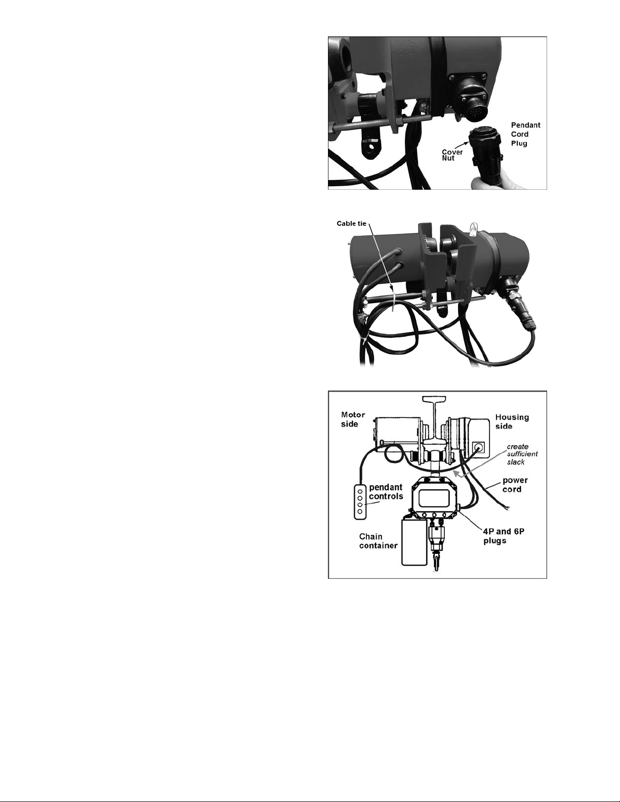
2. Insert the male plug of the pend ant cord into
the socket on the trolley. See Figure 4.
Secure the connection by tightening the
cover nut with your fingers.
3. Attach the pendant cord t o the cord holder.
The cord must be sec ur ed t o th e c ord holder
in a way that relieves strain on the
connections. One method of doing this is to
form a loop in the pendant cord and place
the cable tie as shown in Figure 5. Do not
tighten the cable tie yet.
4. Create sufficient slack in the pendant cord
where it passes under the I- beam (Figur e 6)
so that the cord will not rub against the
beam.
5. Tighten the cable tie to secure the pendant
cord to the cord holder.
7.3 Mounting Your Hoist
This trolley has been des igned to work with the
JET C-Series Hoist. The y can be connected so
that one pendant cord and power cord will
operate both trolley and hoist. Make sure the
hoist has been set to the same voltage
specifications as the trolley.
Make connections fr om the trolley to your hoist
as follows:
1. Hang the hoist on the trolley hanger, using
hook or lug mount. (See page 8 for
instructions on installing the optional lug
mount.) The hoist should be positioned so
that the electrical so cket on the trolle y is on
the same side as the sockets on the hoist,
as shown in Figure 6.
Figure 4
Figure 5
2. Remove the power cord and pendant cord
from the hoist.
3. Connect the two 4P and 7P plugs of the
trolley cords into their appropriate sockets
on the hoist.
Figure 6
7
Page 8
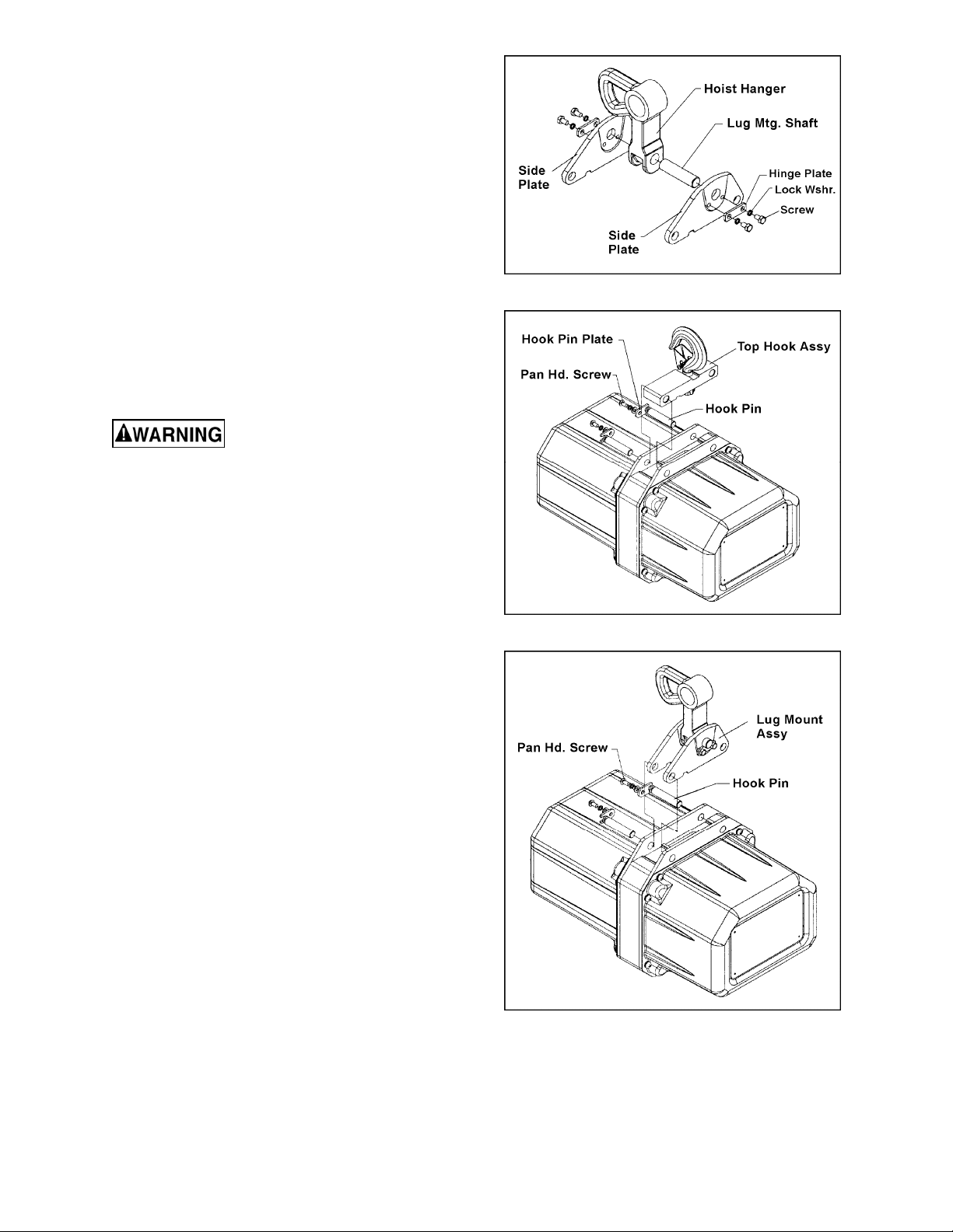
7.4 Installing Lug Mount Accessory
1. Assemble the side plates, hoist ha nger and
lug mounting shaft, as shown in Figure 7.
2. Install the hinge plates, lock washers and
hex cap screw to secure the assembly.
3. On the electric hoist, remove the two
screws, hook pin plate, hook pin, etc.
(Figure 8)
4. Remove the top hook assembly from the
hoist, and replace it with the lug mount
accessory as shown in Figure 9. Re-install
the hook pins, hook pin plates, screws and
washers. Firmly tighten the screws.
8.0 Electrical Instructions
Electrical connections must
be made by a qualified electrician in
compliance with all relevant codes. This
machine must be properly grounded to help
prevent electrical shock and possible fatal
injury.
8.1 Grounding
In the event of a malfunction or breakdown,
grounding provides a path of least res istance f or
electric current to reduce the risk of electric
shock.
This machine’s power cord must be fitted with
an appropriate UL/CS A listed plug, or it can be
“hard-wired” directly to a control panel. If hardwired, make sure a disconnect is available for
the operator.
Figure 7
Figure 8
If a plug is installed, it m ust have an equipm entgrounding conductor and a grounding prong.
The plug must be plugged into a m atching outle t
that is properly installed and grounded in
accordance with all local codes and ord inances.
Do not modify the plug.
Improper connection of the equipmentgrounding conductor can result in a risk of
electric shock. The conductor with insulation
having an outer surface that is green with or
without yellow stripes is the equipmentgrounding connector. If repair or replacement of
the electric cord or plug is necessary, do not
connect the equipment-gr ounding c onductor to a
live terminal.
Figure 9
8
Page 9

Check with a qualified electrician or service
personnel if the grounding instructions are not
completely understood, or if in doubt as to
whether the tool is properly grounded.
Repair or replace damaged or worn cord
immediately.
8.2 Voltage Conversion
The single phase models (ET-1C) are
designed for 115 volt or 23 0 volt oper atio n. T hey
are pre-wired for 230 volt. The three phase
models (ET-3C) are designed for 230 volt or
460 volt operation. They are pre-wired for 460V.
To switch voltage :
1. Disconnect trolley from power supply, and
disconnect the pendant cord from the trolley.
2. Remove the two screws and lock washers
on the underside of the housing (s ee Figure
10) and slide the protect ive band out of the
way. Remove the housing.
3. Carefully pull the plug out of the current
socket and insert it into the new sock et (see
Figure 10). Make sur e the notch on the plug
fully engages the socket.
4. Re-install the housing, re-position the
protective band, and insert the screws and
lock washers. Tighten the screws securely.
Test the motion of the hoist also:
2. With no load o n the load h ook, pr ess the U P
button very briefly and observe ho ist action.
The hook should m ove upward. (Two speed
models have a two-position UP button.
Press the button onl y part wa y to operate l ift
motor at slow speed, press fully to operate
at high speed.)
3. If no motion occurs when the UP button is
pressed and the hoist is connected to a
three phase power supply, the po wer supply
wires are incorrectly positioned.
4. Switch any two of the three suppl y wires at
the power source. Do not attempt to rewire
the hoist/trolley circuit or pendant
controls for this problem. Use the same
safety precautions when reversing two of the
supply wires as was used when the wires
were originally connected.
5. Re-connect power and test hoist and trolley
movement again without load. Run hoist to
the complete lifting height to ensure limit
switches are operating properly.
Refer to your hoist manual for more detailed
instructions on operation and testing of the hoist.
8.4 Extension Cords
If an extension cord is nece ssar y, make s ure the
cord rating is suitable f or the am perage lis ted on
the trolley’s motor plate. An undersize cord will
cause a drop in line voltag e resulting in loss of
power and overheating.
Figure 10
8.3 Inspecting Trolley Motion
1. Before closing the circuit break er and tes t ing
the trolley, check that wiring has been
complete. If the trolley cannot be observed
when the circuit breaker is closed, s tation a n
observer within sight of the trolley to report
any movement when powe r is applied to the
trolley. Be prepared to disconnect power if
trolley motor starts when the power is
applied. The trolle y must remain motionless
when power is applied. F ind and cor rect a ny
problems before continuing.
The chart in Figure 11 shows the correct size
cord to use based on cord length and motor
plate amp rating. If in doubt, use the next
heavier gauge. T he smaller the gauge number,
the heavier the cord.
Recommended Gauges (AWG) of Extension Cords
Extension Cord Length *
25
50
75
100
150
Amps
< 5 16 16 16 14 12 12
5 to 8 16 16 14 12 10 NR
8 to 12 14 14 12 10 NR NR
12 to 15 12 12 10 10 NR NR
15 to 20 10 10 10 NR NR NR
21 to 30 10 NR NR NR NR NR
*based on limiting the line voltage drop to 5V at 150% of the
rated amperes.
NR: Not Recommended.
feet
feet
feet
feet
feet
200
feet
Figure 11
9
Page 10

9.0 Control Pendant Accessories
Pendants with 4 buttons are for Lifting and Lowering, and 2-direction Trolley travel.
152411 Single Speed, 4 Button Control Pendant with 10’ Lift.
152416 Single Speed, 4 Button Control Pendant with 15’ Lift.
152421 Single Speed, 4 Button Control Pendant with 20’ Lift.
153431 Single Speed, 4 Button Control Pendant with 30’ Lift.
10.0 Troubleshooting the ET-C Series Trolleys
Trouble Probable Cause Remedy
Trolley will not
operate, or operates
intermittently.
Trolley drifts
excessively after
stopping.
Hoist moves in wrong
direction.
Check trolley connections to power
source. Make sure power source
No incoming power, or low voltage.
Fuse blown or circuit breaker tripped. Replace fuse/reset circuit breaker.
Thermal overload protector has
tripped; motor overheated.
Conductors in pendant cord
damaged.
Motor damaged.
Grease or oil on the brake lining.
Brake pad is worn or damaged. Replace brake pad.
Two of the three power supply wires
are switched.
matches specifications on trolley
name plate. If low voltage, have
certified electrician check incoming
power.
See “Motor overheats” below.
Check for continuity in each
conductor. If faulty, replace entire
pendant cord.
Have motor inspected and repaired/
replaced by a qualified service
technician.
Open the trolley, disassemble the
brake and clean the lining.
Switch any two of the three supply
wires.
Excessive load or too frequent use.
Motor overheats.
Brake is dragging.
Operate within rated load and
according to duty cycle rating.
Have brake repaired or replaced by a
qualified service technician.
11.0 Replacement Parts
Replacement parts are lis ted on the fol lowing pag es. To order parts or reach our service de partm ent, call
1-800-274-6848 Monday through Friday, 8:00 a.m. to 5:00 p.m. CST. Having the Model Number and
Serial Number of your machine available when you call will allow us to serve you quickly and accurately.
Non-proprietary parts , such as fas teners, can be foun d at local hard ware stores, or may be ordered f rom
JET. Some parts are shown for reference only, and may not be available individually.
10
Page 11
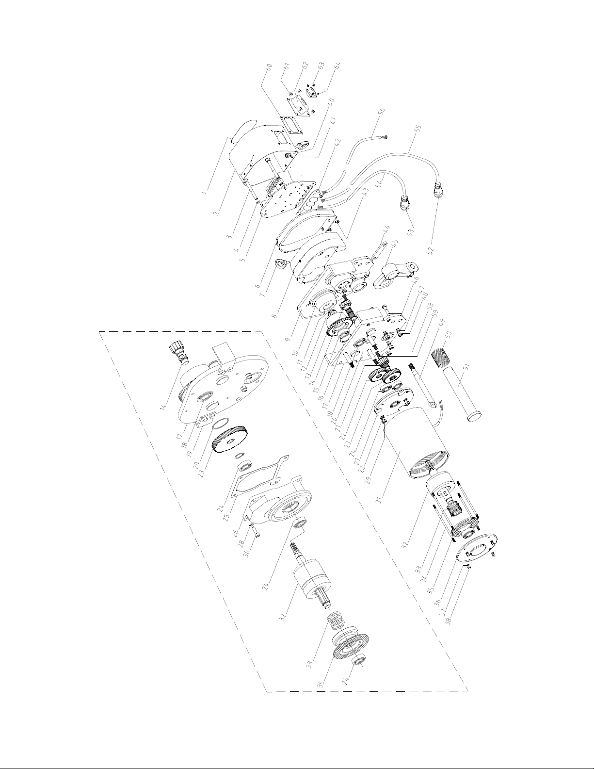
11.1.1 ET-C Series Trolley – Exploded View
Y
L
N
O
E
S
A
H
P
E
E
R
H
T
D
N
A
E
L
G
N
I
S
N
I
T
E
5
&
3
R
O
F
11
Page 12

11.1.2 ET-C Series Trolley – Parts List
Index No. Part No. Description Size Qty
1 ................ LM000123 ........ Name Plate (1/2T, three phase) .............................. ....................................... 1
.................. LM000124 ........ Name Plate (1T, three phase) ................................. ....................................... 1
.................. LM000125 ........ Name Plate (2T, three phase) ................................. ....................................... 1
.................. LM000126 ........ Name Plate (3T, three phase) ................................. ....................................... 1
.................. LM000127 ........ Name Plate (5T, three phase) ................................. ....................................... 1
.................. LM000128 ........ Name Plate (1/2T, single phase) ............................. ....................................... 1
.................. LM000129 ........ Name Plate (1T, single phase) ................................ ....................................... 1
.................. LM000130 ........ Name Plate (2T, single phase) ................................ ....................................... 1
.................. LM000131 ........ Name Plate (3T, single phase) ................................ ....................................... 1
.................. LM000132 ........ Name Plate (5T, single phase) ................................ ....................................... 1
2 ................ 1ET-3C-2G ...... Housing (1/2T,1T,2T,3T,5T) .................................... ....................................... 1
3 ................ 1ET-3C-3 ......... Socket Head Cap Screw (1/2T,1T,2T,3T,5T) .......... M8x70 ............................ 2
4 ................ 1ET-3C-4 ......... Lock Washer (1/2T,1T,2T,3T,5T) ............................ 8mm ............................... 7
5 ................ 1ET-3C-5 ......... Electrical Board (1/2T,1T,2T, three phase) ............. ....................................... 1
.................. 3ET-3C-5 ......... Electrical Board (3T, 5T, three phase) .................... ....................................... 1
.................. 1ET-1C-5 ......... Electrical Board (1/2T,1T,2T, single phase) ............ ....................................... 1
.................. 3ET-1C-5 ......... Electrical Board (3T,5T, single phase) .................... ....................................... 1
6 ................ 1ET-3C-6 ......... Protective Band (1/2T,1T,2T,3T,5T) ........................ ....................................... 1
7 ................ 1ET-3C-7 ......... Eye Bolt (1/2T,1T,2T,3T,5T) .................................... M8x16 ............................ 2
8 ................ 1ET-3C-8G ...... Balance Spacer (1/2T,1T,2T) .................................. ....................................... 1
.................. 3ET-3C-8G ...... Balance Spacer (3T,5T) .......................................... ....................... ................ 1
9 ................ 1ET-3C-9G ...... Plain Side Plate Ass embly (1/2T,1T) ....................... ....................................... 1
.................. 2ET-3C-9G ...... Plain Side Plate Assembly (2T) ............................... ....................................... 1
.................. 3ET-3C-9G ...... Plain Side Plate Assembly (3T) ............................... ....................................... 1
.................. 5ET-3C-9G ...... Plain Side Plate Assembly (5T) ............................... ....................................... 1
10 .............. 1ET-3C-10 ....... Plain Wheel (1/2T,1T).............................................. ....................................... 2
.................. 2ET-3C-10 ....... Plain Wheel (2T) ...................................................... ....................................... 2
.................. 3ET-3C-10 ....... Plain Wheel (3T) ...................................................... ....................................... 2
.................. 5ET-3C-10 ....... Plain Wheel (5T) ...................................................... ....................................... 2
11 .............. 1ET-3C-11 ....... Circlip for shaft (1/2T,1T) ......................................... Ø17mm .......................... 4
.................. 2ET-3C-11 ....... Circlip for shaft (2T) ................................................. Ø 25mm ......................... 4
.................. 3ET-3C-11 ....... Circlip for shaft (3T) ................................................. Ø 30mm ......................... 4
.................. 5ET-3C-11 ....... Circlip for shaft (5T) ................................................. Ø 35mm ......................... 4
12 .............. 1ET-3C-12 ....... Washer (1/2T,1T) .................................................... ....................................... 4
.................. 2ET-3C-12 ....... Washer (2T) ............................................................. ....................................... 4
13 .............. 1ET-3C-13 ....... Geared Wheel (1/2T,1T).......................................... ....................................... 2
.................. 2ET-3C-13 ....... Geared Wheel (2T) .................................................. ....................................... 2
.................. 3ET-3C-13 ....... Geared Wheel (3T) .................................................. ....................................... 2
.................. 5ET-3C-13 ....... Geared Wheel (5T) .................................................. ....................................... 2
14 .............. 1ET-3C-14 ....... Fifth Gear (1/2T,1T,2T)............................................ ....................................... 1
.................. 3ET-3C-14 ....... Fifth Gear (3T,5T) .................................................... ....................................... 1
15 .............. 1ET-3C-15 ....... Roller Bearing (1/2T,1T) .......................................... 6203-2Z .......................... 4
.................. 2ET-3C-15 ....... Roller Bearing (2T) .................................................. 6205-2Z .......................... 4
.................. 3ET-3C-15 ....... Roller Bearing (3T) .................................................. 6206-2Z .......................... 4
.................. 5ET-3C-15 ....... Roller Bearing (5T) .................................................. 6207-2Z .......................... 4
16 .............. 1ET-3C-16 ....... Circlip for hole (1/2T,1T) .......................................... 40mm ............................. 4
.................. 2ET-3C-16 ....... Circlip for hole (2T) .................................................. 52mm ............................. 4
.................. 3ET-3C-16 ....... Circlip for hole (3T) .................................................. 62mm ............................. 4
.................. 5ET-3C-16 ....... Circlip for hole (5T) .................................................. 72mm ............................. 4
17 .............. 1ET-3C-17G .... Gear Side Plate Assembly (1/2T,1T) ....................... ....................................... 1
.................. 2ET-3C-17G .... Gear Side Plate Assem bl y (2T) ............................... ....................................... 1
.................. 3ET-3C-17G .... Gear Side Plate Assem bl y (3T) ............................... ............................
.................. 5ET-3C-17G .... Gear Side Plate Assem bl y (5T) ............................... ....................................... 1
18 .............. 1ET-3C-18 ....... Roller Bearing (1/2T,1T,2T) ..................................... 6004-2ZN ....................... 1
.................. 3ET-3C-18 ....... Roller Bearing (3T,5T) ............................................. 6205-2ZN ....................... 1
19 .............. 3ET-3C-19 ....... Safety Block (3T) ..................................................... ....................................... 4
.................. 5ET-3C-19 ....... Safety Block (5T) ..................................................... ....................................... 4
........... 1
12
Page 13

Index No. Part No. Description Size Qty
20 .............. 1ET-3C-20 ....... Roller Bear ing w/S nap Rin g (1/2T ,1T ,2T) ............... 42m m ............................. 1
.................. 3ET-3C-20 ....... Roller Bearing w/S nap Rin g (3T ,5T ) ....................... 52mm ............................. 1
21 .............. 1ET-3C-21 ....... Third Gear (1/2T,1T,2T) .......................................... ....................................... 1
22 .............. 1ET-3C-22 ....... Fourth Gear (1/2T,1T,2T) ........................................ ....................................... 1
23 .............. 1ET-3C-23 ....... Second Gear (1/2T,1T,2T) ...................................... ....................................... 1
.................. 3ET-3C-23 ....... Second Gear (3T,5T) ............................................... ....................................... 1
24 .............. 1ET-3C-24 ....... Roller Bearing (1/2T,1T,2T) ..................................... 6003-2Z .......................... 4
.................. 3ET-3C-24 ....... Roller Bearing (3T,5T) ............................................. 6004-2Z .......................... 4
25 .............. 3ET-3C-25 ....... Gear Case Gasket (3T,5T) ...................................... ....................................... 1
26 .............. 3ET-3C-26G .... Gear Case (3T,5T) .................................................. ....................................... 1
27 .............. 1ET-3C-27 ....... Flange (1/2T,1T,2T) ................................................. ....................................... 1
28 .............. 1ET-3C-28 ....... Lock Washer (1/2T,1T,2T,3T,5T) ............................ 8mm ............................... 4
29 .............. 1ET-3C-29 ....... Hex Nut (1/2T,1T,2T) ............................................... M8 .................................. 3
30 .............. TS-1504051 ..... Socket Head Cap Screw (3T,5T) ............................ M8x25 ............................ 4
31 .............. 1ET-3C-31G .... Motor Case Assembly (1/2T,1T,2T, three phase) ... ....................................... 1
.................. 3ET-3C-31G .... Motor Case Assembly (3T,5T, three phrase) .......... ....................................... 1
.................. 1ET-1C-31G .... Motor Case Assembly (1/2T,1T,2T,single phase) ... ....................................... 1
.................. 3ET-1C-31G .... Motor Case Assembly (3T,5T, single phase) .......... ....................................... 1
32 .............. 1ET-3C-32 ....... Rotor Assembly (1/2T,1T,2T three phrase) ............. ....................................... 1
.................. 3ET-3C-32 ....... Rotor Assembly (3T,5T, three phrase) .................... ....................................... 1
.................. 1ET-1C-32 ....... Rotor Assembly (1/2T,1T, 2T single phase) ............ ....................................... 1
.................. 3ET-1C-32 ....... Rotor Assembly (3T,5T, single phase) .................... ....................................... 1
33 .............. 3ET-3C-33 ....... Brake Spring (1/2T,1T,2T,3T,5T) ............................ ....................................... 1
34 .............. 1ET-3C-34 ....... Motor Stay Bolt (1/2T,1T,2T) ................................... ....................................... 4
.................. 3ET-3C-34 ....... Motor Stay Bolt (3T,5T) ........................................... ....................................... 4
35 .............. 3ET-3C-35 ....... Friction Pad Assembly (1/2T,1T,2T,3T,5T) ............. ....................................... 1
36 .............. 1ET-3C-36G .... Motor End Plate (1/2T,1T,2T,3T,5T) ....................... ....................................... 1
37 .............. 1ET-3C-37 ....... Lock Washer (1/2T,1T,2T,3T,5T) ............................ 5mm ............................... 4
38 .............. 1ET-3C-38 ....... Acorn Nut (1/2T,1T,2T,3T,5T) ................................. M5 .................................. 4
40 .............. 1ET-3C-40 ....... Lock Washer (1/2T,1T,2T,3T,5T) ............................ 8mm ............................... 1
41 .............. 1ET-3C-41 ....... Hex Nut (1/2T,1T,2T,3T,5T) .................................... M8 .................................. 1
42 .............. 1ET-3C-42 ....... Cable Press Plate (1/2T,1T,2T,3T,5T) .................... ....................................... 1
43 .............. 1ET-3C-43 ....... Phillips Pan Head Screw (1/2T,1T,2T,3T,5T) ......... M5x 10 ............................ 2
44 .............. 1ET-3C-44 ....... Plate Key (1/2T,1T) ................................................. ....................................... 1
.................. 2ET-3C-44 ....... Plate Key (2T) .......................................................... ....................................... 1
.................. 3ET-3C-44 ....... Plate Key (3T) .......................................................... ....................................... 1
.................. 5ET-3C-44 ....... Plate Key (5T) .......................................................... ....................................... 1
45 .............. 1ET-3C-45 ....... Hoist Hanger (1/2T,1T) ............................................ ....................................... 1
.................. 2ET-3C-45 ....... Hoist Hanger (2T) .................................................... ....................................... 1
.................. 3ET-3C-45 ....... Hoist Hanger (3T) .................................................... ....................................... 1
.................. 5ET-3C-45 ....... Hoist Hanger (5T) .................................................... ....................................... 1
46 .............. 1ET-3C-46 ....... Hex Cap Screw (1/2T,1T) ........................................ M8x40 ............................ 8
.................. 2ET-3C-46 ....... Hex Cap Screw (2T) ................................................ M10x45 .......................... 8
.................. 3ET-3C-46 ....... Hex Cap Screw (3T) ................................................ M10x50 .......................... 8
.................. 5ET-3C-46 ....... Hex Cap Screw (5T) ................................................ M14x65 .......................... 8
47 .............. 1ET-3C-47 ....... Lock Washer (1/2T,1T) ............................................ 8mm ............................... 8
.................. 2ET-3C-47 ....... Lock Washer (2T) .................................................... 10mm .............. ............... 8
.................. 3ET-3C-47 ....... Lock Washer (3T) .................................................... 10mm .............. ............... 8
.................. 5ET-3C-47 ....... Lock Washer (5T) .................................................... 14mm .............. ............... 8
48 .............. 1ET-3C-48 ....... Hex Nut (1/2T,1T) .................................................... M8 .................................. 8
.................. 2ET-3C-48 ....... Hex Nut (2T) ............................................................ M10 ................................ 8
.................. 3ET-3C-48 ....... Hex Nut (3T) ............................................................ M10 ...........
.................. 5ET-3C-48 ....... Hex Nut (5T) ............................................................ M14 ................................ 8
49 .............. 1ET-3C-49 ....... Cord Holder (1/2T,1T,2T,3T,5T) .............................. ....................................... 1
50 .............. 1ET-3C-50 ....... Spacer (1/2T,1T) ..................................................... ..................................... 16
.................. 2ET-3C-50 ....... Spacer (2T) .............................................................. ..................................... 16
.................. 3ET-3C-50 ....... Spacer (3T) .............................................................. ..................................... 16
.................. 5ET-3C-50 ....... Spacer (5T) .............................................................. ..................................... 16
..................... 8
13
Page 14

Index No. Part No. Description Size Qty
51 .............. 1ET-3C-51 ....... Suspension Shaft (1/2T,1T) .................................... ....................................... 1
.................. 2ET-3C-51 ....... Suspension Shaft (2T) ............................................. ....................................... 1
.................. 3ET-3C-51 ....... Suspension Shaft (3T) ............................................. ....................................... 1
.................. 5ET-3C-51 ....... Suspension Shaft (5T) ............................................. ....................................... 1
52 .............. 1ET-3C-52A ..... Male Plug for 7-Pin (1/2T,1T,2T,3T,5T) .................. YD28K7TQPGB.5 .......... 1
53 .............. 1ET-3C-53A ..... Male Plug for 4-Pin (1/2T,1T,2T,3T,5T) .................. YD24K4TQPGB.5 .......... 1
54 .............. 1ET-3C-54 ....... Coupling Cable P (1/2T,1T,2T,3T,5T) ..................... 1M .................................. 1
55 .............. 1ET-3C-55 ....... Coupling Cable C (1/2T,1T,2T,3T,5T) ..................... 1M .................................. 1
56 .............. 1ET-3C-56 ....... Power Cord (1/2T,1T,2T,3T,5T) .............................. 2M .................................. 1
58 .............. 1ET-3C-58 ....... Hex Nut (1/2T,1T,2T) ............................................... M12 ................................ 3
.................. 3ET-3C-58 ....... Hex Nut (3T,5T) ....................................................... M16 ................................ 3
59 .............. 1ET-3C-59 ....... Threaded Shaft (1/2T,1T) ........................................ ....................................... 1
.................. 2ET-3C-59 ....... Threaded Shaft (2T) ................................................ ....................................... 1
.................. 3ET-3C-59 ....... Threaded Shaft (3T) ................................................ ....................................... 1
.................. 5ET-3C-59 ....... Threaded Shaft (5T) ................................................ ....................................... 1
60 .............. 1ET-3C-60 ....... Seal Gasket (1/2T,1T,2T,3T,5T) ............................ ....................................... 1
61 .............. TS-1533042 ..... Phillips Pan Head Machine Screw (1/2T,1T,2T,3T,5T)…M5X12 .................... 4
62 .............. 1ET-3C-52 ....... Connector Case (1/2T,1T,2T,3T,5T) ....................... ....................................... 1
63 .............. 1ET-3C-63 ....... Female Plug (1/2T,1T,2T,3T,5T) ............................. YD28J15Z ...................... 1
64 .............. 1ET-3C-64 ....... Phillips Pan Head Machine Screw (1/2T,1T,2T,3T,5T)…M3X14 .................... 4
14
Page 15

11.2.1 Lug Mount Assembly (Optional) for SS-3C,SS-1C Hoists
For Electric Hoists in 1/2T, 1T and 2T
Index No. Part No. Description Size Qty
................. 1/2SS-3C-LMA ......... Lug Mount Assembly (1/2T) (includes #1 and 3-7) .....................................
................. 1SS-3C-LMA ............ Lug Mount Assembly (1T) (includes #1 and 3-7) ........................................
................. 2SS-3C-LMA ............ Lug Mount Assembly (2T) (includes #1 and 3-7) ........................................
1 ............... 1/2SS-3C-116 .......... Side Plate L.H. (1/2T) ....................................... ....................................... 1
................. 1SS-3C-116 ............. Side Plate L.H. (1T) .......................................... ....................................... 1
................. 2SS-3C-116 ............. Side Plate L.H. (2T) .......................................... ....................................... 1
2 ............... 1ET-3C-45 ............... Hoist Hanger (1/2T,1T)* .................................... ....................................... 1
................. 2ET-3C-45 ............... Hoist Hanger (2T)* ............................................ ....................................... 1
3 ............... 1/2SS-3C-118 .......... Lug Mounting Shaft (1/2T,1T) ........................... ....................................... 1
................. 2SS-3C-118 ............. Lug Mounting Shaft (2T) ................................... ....................................... 1
4 ............... 1/2SS-3C-119 .......... Side Plate R.H. (1/2T) ....................................... ....................................... 1
................. 1SS-3C-119 ............. Side Plate R.H. (1T) .......................................... ....................................... 1
................. 2SS-3C-119 ............. Side Plate R.H. (2T) .......................................... ....................................... 1
5 ............... 3SS-3C-061 ............. Hinge Plate........................................................ ....................................... 2
6 ............... 1/2SS-3C-012 .......... Lock Washer ..................................................... 6mm ............................... 4
7 ............... 1/2SS-3C-120 .......... Hex Head Cap Screw ....................................... M6x10 ............................ 4
For Electric Hoists in 3T and 5T
Index No. Part No. Description Size Qty
................. 3SS-3C-LMA ............ Lug Mount Assembly (3T) (includes #1 and 3-7) ........................................
................. 5SS-3C-LMA ............ Lug Mount Assembly (5T) (includes #1 and 3-7) ........................................
1 ............... 3SS-3C-116 ............. Side Plate (3T) .................................................. ....................................... 2
................. 5SS-3C-116 ............. Side Plate (5T) .................................................. ....................................... 2
2 ............... 3ET-3C-45 ............... Hoist Hanger (3T)* ............................................ ....................................... 1
................. 5ET-3C-45 ............... Hoist Hanger (5T)* ............................................ ....................................... 1
3 ............... 2SS-3C-118 ............. Lug Mounting Shaft (3T) ................................... ....................................... 1
................. 5SS-3C-118 ............. Lug Mounting Shaft (5T) ................................... ....................................... 1
5 ............... 3SS-3C-061 ............. Hinge Plate........................................................ ....................................... 2
6 ............... 1/2SS-3C-012 .......... Lock Washer ..................................................... 6mm ............................... 4
7 ............... 3SS-3C-120 ............. Hex Head Cap Screw ....................................... M6x12 ............................ 4
* Hoist Hanger comes pre-assembled to the electric trolley.
15
Page 16

11.3.1 ET-C Series Trolley Electrical Components – Exploded View
16
Page 17

11.3.2 ET-C Series Trolley Electrical Components – Parts List
Index No. Part No. Description Size Qty
501 ........... 1ET-3C-501 ............. Electrical Component Board (3Ph) ...................... .................................... 1
................. 1ET-1C-501 ............. Electrical Component Board (1/2T,1T, 2T: 1Ph) .. .................................... 1
................. 3ET-1C-501 ............. Electrical Component Board (3T,5T: 1Ph) ........... .................................... 1
502 ........... 1ET-3C-502 ............. Transformer (3Ph) ................................................ (460/230)/24V ............. 1
................. 1ET-1C-502 ............. Transformer (1Ph) ................................................ (230/115)/24V ............. 1
503 ........... 1ET-1C-503 ............. Capacitor (1/2T,1T,2T: 1Ph) ................................ 65µF ............................ 1
................. 3ET-1C-503 ............. Capacitor (3T,5T: 1Ph) ........................................ 120µF .......................... 1
504 ........... 1ET-1C-504 ............. Capacitor (1/2T,1T,2T: 1Ph) ................................ 16µF ............................ 1
................. 3ET-1C-504 ............. Capacitor (3T,5T: 1Ph) ........................................ 30µF ............................ 1
505 ........... TS-1541001 ............. Lock Nut (1Ph) ..................................................... M4 ............................... 2
506 ........... 1ET-1C-506 ............. Retainer Pin (1Ph) ............................................... .................................... 2
507 ........... 1ET-1C-507 ............. Capacitor Holder (1/2T,1T,2T: 1Ph) .................... .................................... 1
508 ........... TS-1501061 ............. Socket Head Cap Screw (1Ph) ........................... M4x20 ......................... 2
509 ........... 1ET-1C-509 ............. Capacitor Holder (1/2T,1T,2T: 1Ph) .................... .................................... 1
................. 3ET-1C-509 ............. Capacitor Holder (3T,5T: 1Ph) ............................. .................................... 2
510 ........... TS-1541001 ............. Lock Nut (1Ph) ..................................................... M4 ............................... 2
513 ........... TS-1532032 ............. Pan Head Screw (3Ph) ........................................ M4x10 ......................... 5
................. TS-1532032 ............. Pan Head Screw (1Ph) ........................................ M4x10 ......................... 7
514 ........... TS-2361041 ............. Lock Washer (3Ph) .............................................. M4 ............................... 7
................. TS-2361041 ............. Lock Washer (1Ph) .............................................. M4 ............................... 9
515 ........... TS-1550021 ............. Flat Washer (3Ph) ................................................ M4 ............................... 5
................. TS-1550021 ............. Flat Washer (1Ph) ................................................ M4 ............................... 7
516 ........... 1ET-3C-516A ........... Contactor .............................................................. VB6-30-01 ................... 1
517 ........... 1ET-1C-517 ............. Contactor Holder (1Ph) ........................................ .................................... 1
518 ........... TS-1532032 ............. Pan Head Screw .................................................. M4x10 .............. ........... 2
519 ........... 1ET-3C-519 ............. Terminal Board .................................................... .................................... 1
17
Page 18

12.0 Electrical Connections – ET-C Series Trolleys
12.1.1 ET-C Trolley SINGLE PHASE ONLY
18
Page 19
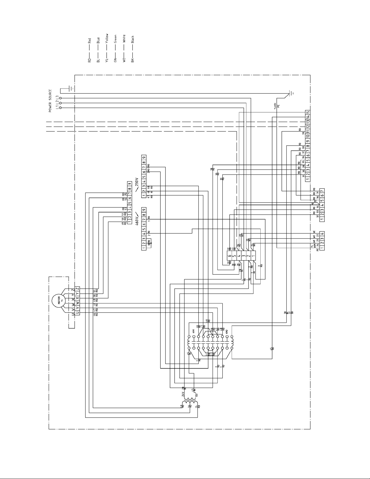
12.1.2 ET-C Trolley – THREE PHASE ONLY
19
Page 20

12.1.3 Electrical Connections – Control Pendants
4-PUSHBUTTON WIRING DIAGRAM
FOR SINGLE SPEED HOISTS
4-PUSHBUTTON WIRING DIAGR AM
FOR DUAL SPEED HOISTS
6-PUSHBUTTON WIRING DIAGRAM
FOR SINGLE SPEED HOISTS
6-PUSHBUTTON WIRING DIAGRAM
FOR DUAL SPEED HOISTS
4-PUSHBUTTON WIRING DIAGRAM
FOR VFD HOISTS
20
 Loading...