

Page 1

Operating Instructions and Parts Manual
Drum Sander
Model: 10-2 0 Plus
WALTER MEIER (Manuf acturing) Inc.
427 New Sanford Road
LaVergne, Tennessee 37086 Part No. M-628900
Ph.: 800-274-6848 Revision C1 01/2010
www.walt er meier.c om Copyright © 2010 Walt er Meier (M anufacturi ng) Inc.
Shown with optional ac cessor ies
Page 2

W arranty and Service
Walter Meier (Manufacturing) Inc., warrants every product it sells. If one of our tools needs service or repair, one of
our Authorized Service Centers located throughout the United States can give you quick service. In most cases, any
of these Walter Meier Authorized Service Centers can authorize warranty repair, assist you in obtaining parts, or
®
perform routine maintenance and major repair on your JET
your area call 1-800-274-6848.
MORE INFORMATION
Walter Meier is consistently adding new products to the line. For complete, up-to-date product information, check with
your local Walter Meier distributor, or visit waltermeier.com.
WARRANTY
JET products carry a limited warranty which varies in duratio n based upon the product (MW = Metalworking, WW =
Woodworking).
WHAT IS COVERED?
This warranty covers any defects in workmanship or materials subject to the e xceptions stated below. Cutting tools,
abrasives and other consumables are excluded from warranty coverage.
WHO IS COVERED?
This warranty covers only the initial purchaser of the product.
WHAT IS THE PERIOD OF COVERAGE?
The general JET warranty lasts for the time period specified in the product literature of each product.
WHAT IS NOT COVERED?
Five Year Warranties do not cover woodworking (WW) products used for commercial, industrial or educational
purposes. Woodworking products with Five Year Warranties that are used for commercial, industrial or education
purposes revert to a One Year Warranty. This warranty does not cover defects due directly or indirectly to misuse,
abuse, negligence or accidents, normal wear-and-tear, improper repair or alterations, or lack of maintenance.
HOW TO GET SERVICE
The product or part must be returned for examination, postage prepaid, to a location designated by us. For the name
of the location nearest you, please call 1-800-274-6848.
You must provide proof of initial purchase date and an explanation of the complaint must accompany the
merchandise. If our inspection discloses a defect, we will repair or replace the product, or refund the purchase price,
at our option. We will return the repaired product or replacement at our expense unless it is determined by us that
there is no defect, or that the defect resulted from causes not within the scope of our warranty in which case we will,
at your direction, dispose of or return the product. In the event you choose to have the product returned, you will be
responsible for the shipping and handling costs of the return.
HOW STATE LAW APPLIES
This warranty gives you specific legal rights; you may also have other rights which vary from state to state.
LIMITATIONS ON THIS WARRANTY
WALTER MEIER (MANUFACTURING) INC., LIMITS ALL IMPLIED WARRANTIES TO THE PERIOD OF THE
LIMITED WARRANTY FOR EACH PRODUCT. EXCEPT AS STATED HEREIN, ANY IMPLIED WARRANTIES OR
MERCHANTABILITY AND FITNESS ARE EXCLUDED. SOME ST ATES DO NOT ALLOW LIMITATIONS ON HOW
LONG THE IMPLIED WARRANTY LASTS, SO THE ABOVE LIMITATION MAY NOT APPLY TO YOU.
WALTER MEIER SHALL IN NO EVENT BE LIABLE FOR DEATH, INJURIES TO PERSONS OR PROPERTY, OR
FOR INCIDENTAL, CONTINGENT, SPECIAL, OR CONSEQUENTIAL DAMAGES ARISING FROM THE USE OF
OUR PRODUCTS. SOME STATES DO NOT ALLOW THE EXCLUSION OR LIMITATION OF INCIDENTAL OR
CONSEQUENTIAL DAMAGES, SO THE ABOVE LIMITATION OR EXCLUSION MAY NOT APPLY TO YOU.
Walter Meier sells through distributors only. The specifications in Walter Meier catalogs are given as general
information and are not binding. Members of Walter Meier reserve the right to effect at any time, without prior notice,
those alterations to parts, fittings, and accessory equipment which they may deem necessary for any reason
®
whatsoever. JET
branded products are not sold in Canada by Walter Meier.
tools. For the name of an Authorized Service Center in
2
Page 3

Table of Contents
Warranty and Service..........................................................................................................................2
Table of Contents ...............................................................................................................................3
Warnings............................................................................................................................................4
In trodu ction ........................................................................................................................................6
Spe cifi cation s .....................................................................................................................................6
Unpacking ..........................................................................................................................................7
Contents of the Shipping Container ..................................................................................................7
Tools Required for Assembly ...........................................................................................................7
Ass embly ...........................................................................................................................................7
10-20 Plus Sander...........................................................................................................................7
Stand..............................................................................................................................................7
Infeed/Outf eed Exte nsion Tables ......................................................................................................7
Installi ng the TrackersTM...................................................................................................................8
El ectric al ............................................................................................................................................9
Electrical Requirements ...................................................................................................................9
Electrical Connect io ns .....................................................................................................................9
Extension Cords ..............................................................................................................................9
Con trol s ...................................................................................................................... ..................... 10
On/Off Switch ................................................................................................................................ 10
Adju s tmen ts ..................................................................................................................................... 11
Drum Height Control ...................................................................................................................... 11
Conveyor Belt Tension................................................................................................................... 11
Conveyor Belt Tracking.................................................................................................................. 11
Drum Alignment ............................................................................................................................ 12
Wrapping Abrasi ve Strips ............................................................................................................... 13
Using the TUF ToolTM .................................................................................................................... 14
Connecting Sander to a Dust Collector ........................................................................................... 15
Setting the Dept h Gauge................................................................................................................ 15
Setting the Dept h of Cut ................................................................................................................. 15
Establishi ng the Proper Dr um Height .............................................................................................. 15
Abrasives ......................................................................................................................................... 16
Ov e rv i e w ...................................................................................................................... ................ 16
Selecting Drum Abrasives .............................................................................................................. 16
Selecting Abrasive Grits ................................................................................................................. 16
Cleaning Abrasive Strips ................................................................................................................ 16
Stretching Abrasive Life ................................................................................................................. 16
Stock Feeding Angle ..................................................................................................................... 17
Multiple-Piece Sanding Runs ......................................................................................................... 17
Edge Sanding ............................................................................................................................... 17
Sanding Imperfect Stock ................................................................................................................ 17
Face Frames and Raised Panel Doors............................................................................................ 17
Mai nten ance .................................................................................................................................... 17
Conveyor Belt Replacement ........................................................................................................... 18
Tension Roller Alignment ............................................................................................................... 18
Tension Roller Pressure Adjustment ............................................................................................... 18
Drum Height Control Adjustment .................................................................................................... 18
Troubleshooting ................................................................................................................................ 19
Parts ................................................................................................................................................ 20
Parts List ...................................................................................................................................... 20
Assembly Drawing......................................................................................................................... 22
Optional Accessories ........................................................................................................................ 23
JET 10-20 Sander Accessor ies ...................................................................................................... 23
JET 10-20 Abrasives ..................................................................................................................... 23
Wiring Diagram................................................................................................................................. 23
Replacement Parts ........................................................................................................................... 23
3
Page 4

Warnings
1. Read and understand t he entire owner's ma nual before at t empting assemb ly or oper ation.
2. Read and understand the war nings post ed on the machine and in this manual. Fa ilure t o comply with
all of these warnings may cause serio us injury.
3. Replace the warning labels if they become obscured or removed.
4. This drum sander is desig ned a nd inte nded for use by properly trai ned and exper ienced personnel
only. If you are not famil iar with the proper and safe operat ion of a dr um sander, do not use until
proper t r aining and knowledge have been obtained.
5. Do not use this machine for other than its intended use. If used for other purposes, Walter Meier
(Manufacturing) Inc., disclaims any real or implied w arranty and holds itself harmless f rom any injury
that may result from that use.
6. Always wear approved safety glasses/face shields while using this machine. Everyday eyeglasses
only have impact r esistant lenses; t hey are not safety glasses.
7. Before operating this machine, remo ve tie, rings, watches and other jewelr y, and roll slee ves up past
the elbows. Remove all loose clot hing and confine lo ng hair. No n-slip footw ear is r ecommended.
8. Wear ear pr otect or s (plugs or muff s) during extended periods of operation.
9. This dr um sa nder is t o be us ed wit h wood and w ood prod ucts only. Use of t his drum sa nder and a
dust collector with metal products is a potential fire hazard.
10. Some dust created by power sanding, sawing, grinding, drilling and other construction activities
contain chemicals k nown to cause cancer, birt h defects or ot her reproductive harm. Some e xamples
of these chemicals are:
• Lead from lead based paint.
• Crystalline silica from bricks, cement and ot her masonry products.
• Arsenic and chromium fr om chemically treated lumber.
Your risk of exposure varies, depending on how often you do this type of work. To reduce your
exposure to these chemicals: work in a well-ventilated area and work with approved safety
equipment, such as face or dust masks that are specifically designed to filter out microscopic
particles.
11. Do not operate this sander while tired or under the influence of dr ugs, alco hol or any medicatio n.
12. Make cer t ain the switch is in the OFF position before co nnecti ng the machine to the power supply.
13. Always sand with t he grain of the wood.
14. Always f eed st ock against the rotat ion of the drum.
15. Do not sand pieces of material that ar e t oo small to be safely supported.
16. When sandi ng a large piece, provide additio nal support at table he ight.
17. Always connect a nd use a dust collector to t he drum sander w hile operating.
18. Make cer t ain the machine is properly grounded.
19. Make all machine adjustme nts or maintenance with the machine unplugged from the power source.
20. Remove adjusting keys and wrenches. Form a habit of checking to see that keys and adjusting
wrenches are removed from the mac hine before tur ning it on.
21. Keep mac hine guards i n place at al l times w hen the machine is i n use. I f removed for mainte nance
purposes, use extreme cautio n and replace t he guards immed iately.
22. Make sure the drum sander is firmly sec ured to t he stand or bench before use.
4
Page 5

23. Check damaged parts. Before further use of the machine, a guard or ot her part that is damaged
shou ld be c a r e fully checked to determine that it will operate pr oper ly and perfor m its intended f unctio n
– check for alig nme nt of mo ving part s , bindi ng of mo ving parts, breakage of par t s , mounting, and any
other conditions that may affect its operation. A guard or other part that is damaged should be
properly repaired or r eplaced.
24. Provide for adequate space surrounding work area and non-glare, overhead lighti ng.
25. Keep the floor around t he machine clean and free of sc r ap material, oil and grease.
26. Keep visitors a saf e dist ance from the wor k ar ea. Keep children away.
27. Make your workshop child proof with padlocks, master switches or by removing star t er keys.
28. Give your work undivided att ention. Looking aro und, carrying on a conversat ion and “ horse-play” are
careless acts that can result in serio us injury.
29. Stand to o ne side of the co nveyor and make sure no one else is sta nding i n line w ith the co nveyor
while feeding into the machine. T he dr um sa nder operates at high speed and should a part sl ip, it will
exit the mac hi ne at a high rat e of speed and may result i n injuries to anyone standing directly in front
of the infeed. (Keep the conveyor belt clean and check pin-roll adjustments). Maintain a balanced
stance at a ll times so t hat you do not fall or lean against the sanding drum or other mo ving part s . Do
not overreach or use excessi ve force to perform any mac hine operation.
30. Use the right tool. Don’t force a t ool or at t achment to do a job for w hich it was not designed. The right
too l will do t he job be tter and saf e r a t the rat e for which it was des ig ned.
31. Use recommended accessor ies; improper acc essor ies may be ha zardo us.
32. Maintain tools with care. Keep tools sharp and clean for the best and safest performance. Follow
instructions for lubricat ing and changi ng accessori es .
33. Never brush away sawdust while the mac hine is running. Use t he correct s peed and feed for t he tool.
Be sure that the tool is the corr ect one for your operation.
34. Never stand on a machine. Serious injury could occ ur if the machine tipped or if the sand ing drum is
unintentio nally co ntact ed.
35. Never lea ve the machi ne r unning unattended. Turn the pow er of f and don’t leave t he machine until it
comes to a complete stop.
36. All doors should be closed, all panels replac ed and other safety guards should be in place befor e t he
machine is start ed or operat ed.
37. Keep your hands clear when feeding parts onto the conveyor. The part will be forced down as it
begins to feed into the machine, causing a pinching action between the part and the table. Use
caution! Hands should be clear of the stock and t he table to avoid pinching. Never reach into a
running machine. Turn off the electrical power and stop the machine before attempting to retrieve
parts f r om w ithin it. Keep your hands away f r om the sanding area. Contact with inter nal moving parts
can result in the loss or injury to fingers, hands and arms.
38. Remove loose items a nd unnecessary w or k pieces f r om the area befor e starting the machine.
Familiarize yours elf with the f ollow ing saf et y not ices used in t his manual:
This means that if precautions are not heeded, it may result in minor injury and/or
possible machine damage.
This means that if prec autions are not heeded, it may result in serious injury or possibly
even death.
- - SAVE THESE IN STRUCTI ONS - -
5
Page 6

Introduction
This manual is prov ided by JET covering t he safe operat ion and maintenance proc edures for a Model 1020 Plus Drum Sander. This manual contains instructions on installation, safety precautions, general
operating proced ures, ma intenance inst ructions and par ts break down. This machine has been des igned
and constructed t o pr ovide year s of t r ouble free oper at io n if used in accorda nce t o instructions set fort h in
this manual. I f there are a ny q uestions or co mments, please co ntact either yo ur local s upplier or Wa lter
Meier (M anufacturi ng) Inc. Walter M eier c an also be reached at our web site: www.walt er meier.com.
Specifications
Model Number ......................................................................................................................10-20 Plus
Stock Number .......................................................................................................................... 628900
Maximum Width (in) .....................................................................................................20 (Two Passes)
Minimum Length (in) ..................................................................................................................... 2-1/4
Maximum Thickness (in) ..................................................................................................................... 3
Minimum Thickness (in) ................................................................................................................. 1 /32
Drum (in) ...................................................................................................... 5 x 10 Extruded Alumi num
Drum Speed (RPM) ...................................................................................................................... 1700
Dust Chute (in) ................................................................................................................................... 4
Conveyor Motor .............................................................................. 43 inch-lb Torque, Direct Drive, D.C.
Conveyor Variable Feed Rate ( FPM ) .............................................................................................. 0-12
Motor (TEFC) ....................................................................................................... 1 HP, 1Ph, 115V only
Net Weight (lbs) ................................................................................................................................ 96
The specifications in this manual are given as general information and are not binding. Walter Meier
reserves the right to effect, at any time and without prior notice, changes or alterations to parts, fittings,
and accessory equipment deemed nec essar y for any reason whatsoever.
Read and understand the entire contents of this manual before attempting
assembly or operation! Failure to comply may cause serious injury
6
Page 7

Unpacking
Separate all parts from the packing material.
Check each part against the Contents of the
Shipping Container and make certain that all
items are accounted for before discarding any
packing material.
Report any damage to your distributor.
Contents of the Shipping Container
1 ea Sander Assembly (A)
1 ea Handwheel with Handle (B)
2 ea Trackers ( C)
1 ea TUF Tool (D)
1 ea Abrasive Strip (w r apped on the drum)
1 ea Conveyor Belt (at t ached to the base)
1 ea Owner's M anual
1 ea Warranty Card
Hardware Bag (see Note)
4 ea 3/8”- 16x5/8” Hex Cap Screws (E)
4 ea 3/8” Flat W ashers (F)
Note: For attaching Sander to t he optional Open
Stand
Optional Accessories
Optional Accessories are listed on page 23. To
purchase a ny of these accessor ies co ntact your
dealer.
Contents of the Shipping Carton
Tools Required for Assembly
9/16" Wrench
No. 1 or No. 2 Cross Point Screwdriver
1/8" hex wrench
Assembly
10-20 Pl us Sander
Attach the handwheel (B, Fig. 1) to t he height
adjustment screw and tighten with a 1/8" hex
wrench.
Stand
1. If you purchased the optional 10-20 Stand
(A, Fig. 1), assemble it as described in the
manual included wit h the stand.
2. Mount t he 10- 20 Plus Sa nder o n the stand
and secure with four 3/8”-16x5/8” Hex Cap
Screws and four 3/8” Flat Washers (Items
E, F, Contents of the Shipping Carton) and
tighten with a 9/16" wrench.
Figure 1
In f eed/Outfeed Extension Tables
If you purchased the optional 10-20
Infeed/Outfeed Extension Table (not shown),
attach it to the 10-20 Plus Sander as described
in the manual that was included with the
extension tables.
7
Page 8
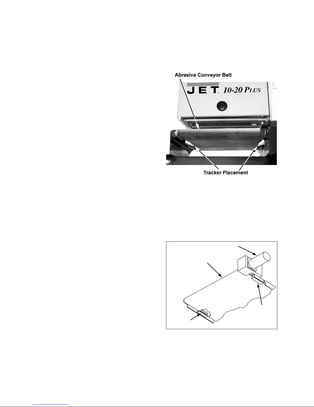
Installing the Trackers
TM
Trackers dramatically reduce tracking
adjustments of t he conveyor belt by guiding the
belt towards the center of the rollers and by
keeping the belt fr om running off t he rollers.
The Trackers are installed on the underside of
the conveyor belt as follows :
1. Disconnect the machine from the power
source.
2. Raise the sanding drum to its highest
position (see Drum Height Control on
page 11).
3. Remove the te nsio n from the c onveyor belt
(Conveyor Belt Tensi on on page 11).
4. Refer ring to Fi gures 2 a nd 3: T he tr acker is
positioned on t he underside of t he conveyor
belt, on the infeed side of the sander,
(closest to the rubber covered drive roller
and gear motor) . The back of the tr acker is
magnetized a nd will stick to t he sidewall of
the conveyor bed. Do not install t he tracker if
the edge of the co nveyor belt is damaged of
torn.
5. When the tracker is installed, slide the
conveyor belt into the bottom slot of the
tracker.
Note: When installed properly, only the
bot tom lip of the tr acker will be visib le. T he
top slot is to be used if the bottom slot w ear s
out.
6. When installing the second tracker, repeat
steps f our and five. Use bot h track er s unless
the conveyor belt is damaged.
Figure 2
Conveyor Drive Motor
7. Make sure all of the switches are off.
Reconnect the power t o the machine.
8. Tension the conveyor belt (see Conveyor
Belt Tension on page 11). Wit h both trackers
installed, it is very important to have equal
tension on both sides of the conveyor belt.
Tighten both sides of the adjustme nt screw s
until equal tension is obtained.
9. Turn the conveyor on full speed and
carefully place both hands o n t he co nveyor
belt to check the tension. If the conveyor belt
can be stopped, continue increasing the
tension until the conveyor belt cannot be
stopped by placing both hands on the belt
while the conveyor is operating at f ull speed.
10. Continue to watch the tracking of the
conveyor belt and adjust it o nly if necess ar y;
do not allow the conveyor belt to buckle
under the conveyor bed.
Abrasive Conveyor Belt
Tracker
8
Figure 3
Tracker
Viewed from underneath
Page 9

Electrical
t
A
Elect ri cal Requirements
When connecti ng the drum sa nder to the pow er
source outlet, the outlet must be properly
grounded to pr otect the operator f rom electrical
shock.
In the event of a malfunction or breakdown,
grounding pro vides a path of least r esist ance for
electrical c urre nt t o reduce the r isk of electr ical
shock. This mac hine is eq uipped with an electr ic
cord having an equipment-grounding conductor
to be inserted into an outlet that is properly
installed and grounded in accordance with all
local codes and ordinances.
Improper connectio n of the equip me nt grounding
conductor ca n result in a risk of electric shock.
The conductor with insulation having an outer
surface that is green (with or without yellow
stripes) is the eq uipment -gr ounding conductor.
If repair or replacement of the electric cord or
plug is necessary, do not connect the
equipment-grounding conductor to a live
terminal.
Important: The adapter illustr at ed in Fig. B is for
use only if you already have a properly
grounded two-prong receptacle. If you are not
sure that yo ur out let is pr operly gro unded, have
it checked by a qualified electricia n.
Before plugging into the
power source, be sure that power switch is
in the OFF position.
Plug power cord into a 110-120V properly
grounded outlet protected by a 14-amp fuse or
circuit breaker .
Do not touch the prongs of
the power cord plug when plugging or
unplugging to or from an outlet .
If improperly grounded, this
power tool can cause serious injury from
electrical shock, particularly when used in
damp locations or near plumbing. If an
electrical sh ock occurs, t here is the potentia l
of a secondary hazard such as y our hands
coming in contact involuntarily with the
rotat ing grinder.
Elect ri cal Connectio ns
The model 10-20 Plus Dr um Sander is rated at
115V, 1Ph. T his sander is designed f or use on a
circuit wit h an outlet that looks the one shown in
Fig. A, and has a groundi ng pro ng, also s how n
in Fig. A. A t emporary adapter (Fig. B) may be
used to connect the plug to a two-prong
receptacle ( Fig. B) if a properly grounded outlet
is not available. A temporary adapter should
only be used until a properly grounded outlet
can be installed by a qualified electrician. This
adapter is not applicable in Canada. The
green colored lug must be fast ened to the cover
plate screw .
Extension Cords
Use only three-wire extension cords that have
three-prong grounding type plugs and threeprong receptacles that accept the tool's plug.
Replace or repair damaged or worn core
immediately.
Use only UL Listed extension cords with this
product.
Improper use of extension cords may cause
inefficient operation of t he sander that ca n result
in overheating. Be sure the extension cord is
rated to allow sufficient current flow to the motor.
For the proper ga uge for the sander in use, see
the chart in Table 1.
Amp
Rating
0 – 05
6 – 10
10 – 12
12 – 16
Volts Total length of cord in fee
120V
240V
25
50
18
18
15
14
50
100
16
16
16
12
100
200
WG
16
14
14
not
recom
Table 1
200
300
14
12
12
not
recom
9
Page 10

Controls
On/Off Switch
Before powering up the unit,
make sure all of t he t ools use d t o assemble and
adjust the unit ar e re moved and a ccounted for.
Make sure your hands, loose clothing and any
other items that may get caught ar e saf ely a way
from the unit.
The On/Off Switch (A, Fig. 4) is located on the front
of the sander. To turn the sander on, pull the switch
to the on position. To turn the sander off, push the
switch to the off position.
Switch Lock
The sander can be locked from unauthorized use
by locking the switch. To lock the switch:
1. Turn the switch to the off position and
disconnect the sander fr om the power source.
2. Pull the key ( C, Fig. 4) out. The switch cannot
be turned on with the key removed.
Should the key be removed
from the switch in the on po sition, the switch
can be turned off but cannot be turned back on.
3. To replace the key, slide the key into the slot
on the switch until it snaps.
Circuit Breaker
The sander is equipped with a motor protective
device (circuit breaker). The breaker will
automatically shut the sander off when excessive
current is consumed.
If the breaker is tripped, turn the sander off and
reset the circuit breaker by pressing the button
(B, Fig. 4).
Be sure to turn the sander off
before resetting the circuit breaker to avoid
unintentionally starting the sander
10
Figure 4
Page 11

Adjustments
Drum Height Control
Drum height is control led by the heigh t adjustmen t
handle (A, Fig. 5). Turning the handwheel in a
counterclockwise direct io n low er s t he drum.
Turning the height adjustment handwheel one
revolutio n lowers t he drum approximately 1/ 16” .
Con veyor Belt Tension
The conveyor belt is overtensioned at the fact ory for sh ipping purposes.
Re-adjust before operation to prevent damage
to the machine.
If the conveyor belt can be stopped by hand
pressure applied directly t o the top of t he conveyor
bed, the belt is too loose. Insufficient belt tension
will c ause slippage of the conveyor belt on t he dri ve
roller during sanding operations.
Excessive belt tension can cause tracking
problems and result in bent rollers, bent take-up
brackets and premature conveyor belt a nd bushing
wear.
Adjust the hex nuts (B, Fig.5) on both sides of the
conveyor to obtai n a snug, and equal ly tens ioned,
conveyor belt. Use the attached wrenches
(C, Fig. 5) to adjust the hex nuts.
Con veyor Belt Tracking
Belt tracki ng adjust ment may be necess ary during
the break-in period and normal operation to
compensate for belt stretching.
Abrasive belt tension must be properly adjusted
before adjusting the tracking. Adjust the belt
tracking while the conveyor belt is running at its
fastes t speed.
Tighte n the hex nut (B, Fig. 5) on t he side t he belt
is drifting towards, and loosen the hex nut on the
opposite side. Use the attached wrenches
(C, Fig, 5) to adjust the hex nuts.
Note: Adjustment should be made in 1/4 turns of
the hex nut. Allow time for the belt to react to the
adjustment. Do not over adjust.
Figure 5
11
Page 12

Drum Alignment
The sanding drum comes preset f r om t he factor y. If
a problem with the drum alignment occ urs, follow
the instructions listed below.
Checking the Drum Alignment
1. Lift the knob (A, F ig. 6) t o open t he dust cover
and remove the abrasive strip. If you are
unsure how to do this, see the “Wrapping
Abrasive Strips” sec t ion in this manual.
2. Using a metal straight edge, or ruler, as a
thickness gauge (B, Fig. 6), insert the gauge
between the drum a nd the conveyor bed on the
outer end of the drum.
3. Open the dust cover and lower the sanding
drum while slowly rotating the drum by hand
until the drum lightly contacts the thickness
gauge.
4. Remove the thickness gauge and place it
under the dr um at t he opposit e end. If the drum
does not contact the thickness gauge to the
same degree as the other end of the drum,
alignment is necessary.
Aligning the Drum
1. Loosen the two socket head button screws
(C, Fig. 7).
2. Lay the thickness gauge under the drum
lengthwise.
3. Adjust the knob, (D, Fig. 7) until the drum
contacts the gauge equally along its entire
surface. Turn the adjusting knob
counterclockwise to lower the outboard e nd of
the drum, a nd clockwise to raise t he o utboard
end of the drum.
4. When the drum is parallel to the conveyor,
tighten the two socket head button screw s.
Fine Tuning Dru m Alignm ent
When sanding boards wider than the drum, drum
alignment is critical and must be ad justed slightly
higher on the outboard end. This will prevent any
ridges from developing in the stock. Alw ays c heck it
on a piece of scrap wood, as follows, before
sanding the work piece.
Run a piece of scr ap wood appro ximate ly 6” wide
by 16” to 18“ long t hrough the sander sideways so
that the e nd of t he board e xtends past the end of
the drum.
Turn the board 180 degrees and sand the same
side without changing t he sanding heig ht.
Figure 6
Figure 7
If a r idge is visible w here the dr um o verlaps, l oos en
the two socket head button screws ( C, Fig. 7) and
turn the adjus ting knob (D, Fig. 7) slightly. Turn the
adjusting knob clockwise to l ower the outboard end
of the drum and counterclockwise to raise it.
Tighten the two hex cap bo lts. Repeat t his process
until the ridge is gone and the entire board is
sanded.
12
Page 13

Wrap ping Ab rasi ve S t rips
Note: When using JET “Ready to Wrap” and
“Ready to C ut” abr asives, not all of t he st eps below
are necessary. You can use the original abrasive
belt that came with the sander as a template for
cutting your own strips.
1. M ark and cut a t aper at one end of the roll, as
shown in Figure 8.
2. Square off the end of the taper, as shown in
Figure 8.
Figure 8
3. Squeeze the fastener lever (A, Fig. 9) on the
outboard end of drum, and insert the tapered
end of the abrasive (B, Fig. 9) so that it uses
most of the width of the slot. Release the
fastener le ver to securely hold the str ip end to
the fastener.
4. The sq uare edge of the abrasive strip should
follow the edge of the drum, as shown in
Figure 9.
Figure 9
Figure 10
5. Wrap the abrasi ve strip around the drum, being
careful not to overlap t he wi ndings, as shown in
Figure 10.
6. Mark the trailing end of the strip where it
crosses t he inboard end of drum (C, Fig. 11).
7. Remove the abrasive strip and cut a taper as
was done with the starting edge (Figure 8).
Note: The taper on the remaining roll can be
used as the taper for the starting edge of the
next strip to be cut.
8. Rewrap the drum starting at the left side as
described in steps 3-5.
9. Sq ueeze the fastener lever o n the inboard e nd
of the drum, and insert the taper ed end of the
abrasive str ip thro ugh the slot i nto t he take- up
fastener.
Position the a brasive strip wit h
sufficient room between the inside of the slot
and the taper ed end of t he st rip t o allow it to be
pulled into the drum as neede d, ( See Figure 12) .
Figure 11
Figure 12
13
Page 14
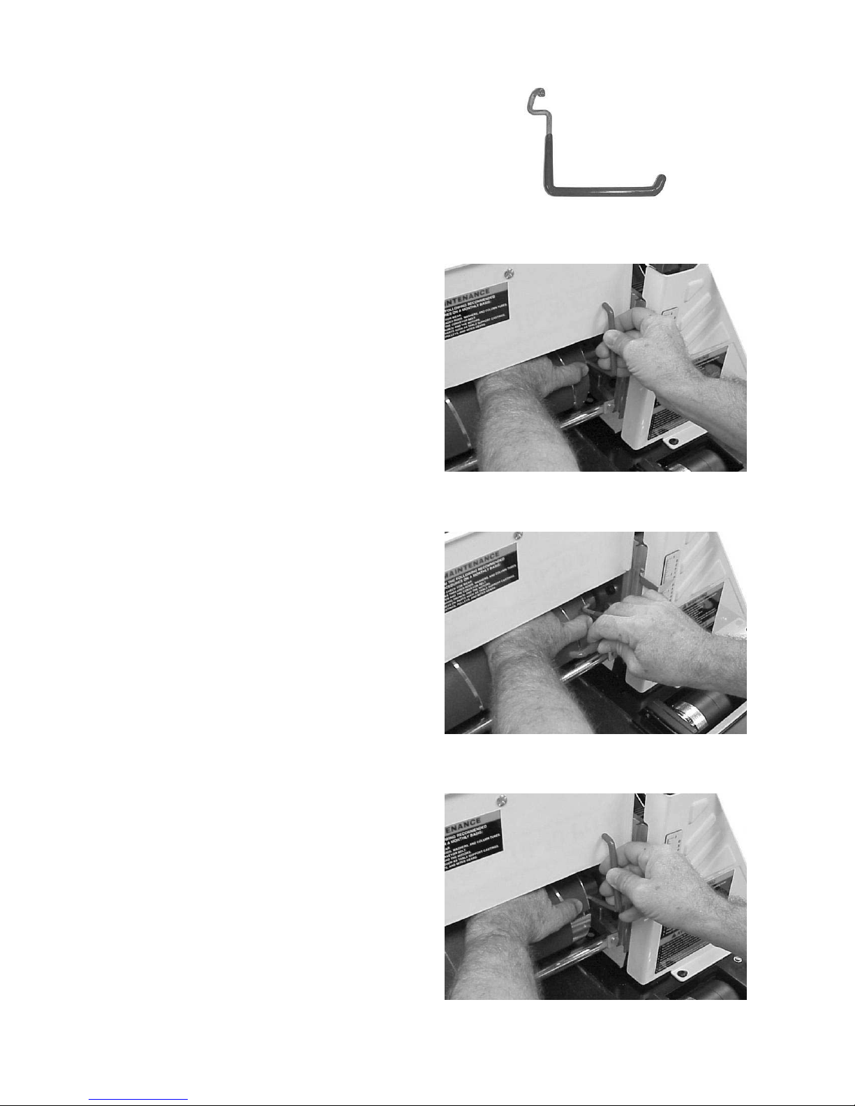
Using the TUF Tool
TM
The Tuf Tool ( F ig ur e 1 3 ) c a n al so be us e d t o ho l d
the take-up fastener in place while you feed the
sandpaper thro ugh the slot.
1. Clip the sandpaper i nto t he outboard faste ner.
Wrap the dr um, being careful not to o verlap the
windings. Hold t he sandpaper o ver the i nboard
slot with the left hand.
2. Hold t he T UF Tool w ith the red e nd of the tool
pointing away fr om you (Figure 14). Insert the
hook into the hole in the end of the take-up
lever of t he fastener (Figure 14).
Figure 13
3. Lift the lever with the TUF Tool, pulling the
lever up until it touches t he inside of t he dr um.
Turn the TUF Too l counter clockwise a nd lower
it onto the sandpaper, making sure it is holdi ng
the sandpaper tight and opening the throat of
the fastener (Figure 15).
4. Insert the tapered end of the paper into t he slot
and the fastener. It may be necessary to trim
the tapered end of the paper so it does not
“bott om out” against the i nside of the drum. Be
sure to leave a gap of at least 1/ 8” bet ween the
tapered st rip and t he closed end of the slot to
allow the str ip to be p ulled into t he faste ner as
needed (Figure 15). If necessary trim the
outside edge of t he paper.
5. Hold the sandpaper in place with your left
hand. Rotate the drum toward you slightly. Pull
up on the TUF Tool and turn the handle
clockwise while maintaining upward pressure.
Slowly move the TUF Tool away from you
slightly, then down, while easing it out of the
hole. This releases the lever into its proper
position. (Fig ure 16).
Figure 14
Figure 15
All abrasive strips will stretch with use and may
stret ch enoug h to allow the take- up lever to reac h
its lowe st posit io n so it ca nnot ma inta in te nsio n o n
the strip. I f this occurs, f ollow t he above proced ures
to reset the take-up lever.
Figure 16
14
Page 15

Con necting Sander to a Dust Collect or
Dust collection is necessary for all drum sanders.
The JET 10-20 is equipped with a 4” dust collection
port in the bac k of the d ust co ver, and is desi gned
to be used with a standard dust collector as show n
in Figure 17.
JET offers a variety of Dust Collectors and Air
Filtratio n Units that will work nicely with your new
sander. Contact your local distributor for more
information.
Setting the Depth Gauge
The depth gauge indicates the distance from the
bottom of the drum to the top of the conveyor.
1. Lower the drum, with the sandpaper installed,
until it touches the conveyor.
2. Loosen the screw (B, Fig. 18).
3. Adjust the pointer (C, Fig. 18) to read zero and
tighten the screw.
Note: Depending on the desired accuracy, you
may need to repeat this process when installing
different sandpaper gr its.
Setting the Depth of Cut
Adjusting t he JET 10-20 for pr oper contact bet w een
the abrasive and the stock is the most important
set-up procedure before operating the sander. It
may take some experimentation to determine the
proper dept h of cut, give n the variables of abrasi ve
grit and ty pes of wood. For best res ults, use scrap
wood to pr ac t ice sanding and to develop your s kil ls
and familiarity with t he machine before doing any
finish work.
A good rule of thumb w hen sanding wit h grits fi ner
than 80 is lower the drum so that it contacts t he
work piece but ca n still be r otated by hand. When
using grits coarser than 80 grit, you can lower t he
drum slightly more. However, a combination of
several variables w ill determine t he pr oper depth of
cut to use, including the following:
! Abrasi ve type and grit size.
! Width of the piece being sanded.
! Hardness of t he piece being sanded.
! Feed rat e of t he piece being sanded.
Figure 17
Figure 18
Establishing the Proper Drum Height
To establish the proper drum height, place the
board to be sanded under the drum and lower t he
drum until it just touches the board. Note: The
sanding drum should still rotate by hand. Without
changing t he dr um heig ht, f inish f eeding t he st ock
under the sander. Start t he sanding drum and sa nd
the board at that same position.
15
Page 16

Abrasives
A
A
Overview
The abrasive material you choose will have a
substantial effect on the performance of your
sander. Var iations in paper t ype, weight, coating
and durability all contribute to achieving your
desired fi nish. For the best sand ing results, JET
offer s premium abrasi ves that ha ve been test ed
and certified for lowest overall cost and
maximum perfor mance. Genuine JET abrasives
are available in pre-cut “Ready- to-W rap” lengths
or in the convenie nt pre- marked “ Ready-to-Cut”
box. These items are listed in the Optional
Accessories sect ion on page 23.
Select i ng Drum Abrasives
To achieve maximum sanding results, it is
important to s elect the proper gr it of abr asive for
the type of sanding being performed. As with
any sanding oper at io n, f irst begin sanding wit h a
coarser gr it, dependi ng on the ro ughness of t he
stock, or the amount of stock to be removed.
Then progressi ve ly work tow ard finer grits. T he
chart below shows the general uses for the
various grits. JET off ers strip rolls in most of the
different abras ive grits shown.
Grit Common Applications
brasive plani ng, surfacing rough-
24
sawn boards, maximum stock
removal, glue removal.
brasive plani ng, surfacing rough
36
sawn boards, maximum stock
removal, glue removal.
Surfacing and dimensioning boards,
60
truing warped boards
Surfacing, light dimensi oning,
80
removing pla ner ripples.
Light sur fa ci ng, removing light planer
100
ripples.
Light sur fa ci ng, minimal stock
120
removal.
Finish sandi ng, minimal stock
150
removal.
Finish sandi ng only, not for stock
180
removal.
Finish sandi ng only, not for stock
220
removal.
Select i ng Abrasive Grit s
The amount of stock to be removed is a major
consideration when choosing the grit grade to
start with. Grits of 24, 36, 50, 60 and 80 are
primarily designed f or st ock removal. Grits of 24
and 36 will remove the most material in one
pass, whether you are doing abrasive planing,
cleaning up glued panels or flattening stock.
Grits from 100 through 220 are primarily
finishing grits designed to remove the scratch
pattern from the previous grit used. For best
results, never skip more than one grit grade
when progressi ng through a sanding sequence.
For fine work, such as furniture, try not to skip
any grit grades during the sanding process. In
general, premium quality abrasives such as
genuine JET abrasives will produce a better
finish with a less noticeable scratch pattern.
Note: Grits that are too fine can sometimes
burnish the wood and leave a glossy surface
that will n ot acc ept st ains e venly. This w ill var y
by the type of wood. Oak, for example, is
susceptible to burnishing because of its open
pores.
Clean i ng Abrasive Strips
A sandpaper cleaning stick may be used to
remove deposits a nd help exte nd sandpaper life.
To use, operat e t he sanding dr um wit h the dust
cover open.
For your own safety, always
wear eye protection while performing
sandpaper cleani ng.
Take all precautions to avoid any contact of
hands or clothing with uncovered drums. Hold
the clea ning stick agai nst t he rotat ing dr um and
move it alo ng t he dr um s urfac e. I t is a good idea
to use a shop brus h or air no zzle to remove any
cleaning stick crumbs from the drums before
resuming sandi ng operatio ns.
Cloth-backed abrasives can be cleaned by
soaking in paint t hinner or mineral spirits f or 20
mi n ut e s t o o ne ho ur . The n us e a nyl o n b rush t o
remove any buildup.
Stretching Abrasive Life
Abrasive life can also be i ncreased by removi ng
the abrasive strip fr om the dr um and reversi ng it .
To do t his, rem ove the strip a nd use w hat was
the trailing end as the starting end on the left
(outboard) side of t he dr um. Reversing t he strip
will p rov ide a f resh set of cutt ing edges o n the
drum.
16
Page 17

Sto ck Feedin g Angle
The optimum stock feeding angle, when
sanding, is at a 60-degr ee angle. However , even
a slight stock feeding angle will provide more
effective stock removal, less loading of
abrasives, lo nger abrasi ve life, pot entia lly fast er
feed rat es and reduced motor loads.
sanding j ust a few i nches of w idt h on the stiles.
To prevent this problem, make s ure that when
using abrasives fi ner then 80 grit, t he drum is in
contact with the wood but can still be spun by
hand.
Maintenance
When fi nish sa nding, the work piece s hould be
fed thro ugh in l i ne with the grain o n the f i nal o ne
or two passes f or the optimum finish.
M ul t i pl e- P iece Sand ing Run s
When abrasi ve plani ng (or t hickness sa nding) a
run of similar pieces that yo u want to ha ve t he
same thickness, it is best to sa nd al l the pieces
at the same time. This way you will be able to
determine the thickness of the thinnest piece
and process all pieces to that same thickness.
Be aw are t hat the sander will remo ve cups a nd
crowns in the work piece; consider this when
measuring the processing stock to the same
thickness.
Edge Sanding
When edg e sa nding, the JET s ander will m imic
the opposite edge of t he stock whic h is lying on
the conveyor belt. Because of this, it is important
for the stock edge to have been ripped at the
proper angle to the face before the sanding
process. When edge sanding stock that is less
than 3/4” wide, or more than 2” high, it is good
procedure to stack and clamp several pieces
together to prevent them from slipping, or
tipping.
For best results, perform the following
recommended maintenance procedures on a
monthl y basi s:
! Lubricat e the co nveyor b us hings and check
for wear.
! Lubricat e all mo vi ng parts , such as threaded
rods, washers and bushings.
! Clean the sawdust from the conveyor belt
and sanding drum.
! Blow the dust from the motors and switches.
Blow the dust fr om the inside of t he sandi ng
drum to preve nt vibr ation. Be caref ul not to
disturb the drum balancing w eig hts.
! Check all the setscrews for tightness on
parts such as bearings, the conveyor and
couplings.
Sanding Im perfect Sto ck
When sanding stock with a cup or crown, place
the crown up. This will stabil ize the stock to help
prevent tipp ing or rock ing dur ing sandi ng. (After
the crown has been removed a nd the top is flat,
turn the stock o ver and sand the oppos ite side.)
To avoid pers onal injury, t ak e special care w hen
sanding stock that is twisted, bowed or
otherwise varies i n thickness from end to end. If
possible, support such stock as it is being
sanded to keep it from slipping, or t ipping. Use
extra roller sta nds, help from a nother perso n, or
hand pressure on the stock to minimize
potentially hazardous situations.
Face F rames and Raised Pan el Doors
It is very import ant t o have the proper abrasi ve
contact when doing this type of sanding. If the
sander is set t o take a n excessive dept h of c ut,
the result can be a gouge, or dip as the drum
goes from sanding the rails at full width to
17
Page 18

Con veyor Belt Replacemen t
To replace the conveyor belt:
1. Disconnect the machine from the power
source.
2. Raise the drum to its highest position us ing
the handwheel ( A, Fig. 19).
3. Remove the belt tensio n by loosening both
take-up nuts (B, Fig. 19) .
4. Unscrew the three screws (D, Fig. 19) that
attach the conveyor to t he bracket .
5. Unbolt t he two hex head s cr ews ( C, Fig. 19)
that hold the bracket to t he bench or stand.
6. Slide t he conveyor belt off the conveyor and
replace it wit h a new belt.
7. Reverse the proced ure for installation.
Tension Roller Alignment
1. Remove the abrasive stri p (E, Fig. 20) from
the drum.
2. Loosen the two bear i ng hex nuts ( F, Fi g. 20)
on the outboard side of the drum and two
cap screws on the inboard side (G, Fig. 20).
Figure 19
3. This will allow the tension roller s to drop to
their lowest posit ion.
4. Lower the sanding drum so that it just
touches the conveyor bed.
5. Turn the drum height handle one complete
revolution to raise the drum.
6. Retig hten t he bearing hex nuts and t he cap
screws.
Ten si on Roll er P ressure Adjustment
You can also adjust the spring-loaded screws
(H, Fig. 20), found on the pressure roller
brackets, to increase or decrease roller
pressure. If you are getting snipe marks at the
leading e nd of the board adjust t he outfeed r oller
pressure. If the snipe marks oc cur on the trailing
end of the board, adjust the infeed roller
pressure.
Drum Height Control Adjustment
If the height control mechanism does not
operate easily or smo othly, or there is excessive
vertical moveme nt of the drum carr iage, per f or m
the following adjustments.
Figure 20
Figure 21
1. To red uce t he handwheel back lash, tighten
the locknut o n t he he ig ht ad jus t me nt s cr ew
(J, Fig. 21).
2. Thoroughly lubricate all mating surfaces
(K, Fig. 21) and height adjustme nt scr ew.
18
Page 19

Troubleshooting
Alig
A
A
A
A
Adj
A
Problem Possible Cause Solution
Conveyor belt does
not move.
Conveyor rollers run
intermittently.
brasive str ip comes
off drum.
brasive str ip is
loose.
brasive loads up
prematurely.
Line or groove in
stock.
Wood burns.
Board slips on
conveyor belt.
Sander motor slows
or stalls
Rippled sanded
surface
Non-uniformly
paced ripples.
Unifor mly spaced
ripples.
Gouging of the
wood.
Snipes Improper t ension on rollers See tension roller adjustment.
Motor overload
protect or tr ips or
shop wiring breaker
trips.
Shaft coupler is not attached. Attach the shaft coupler.
Shaft coupling is loose.
Slack in abrasive strip on
drum.
Abrasive improperly w r apped.
Str ip c aught on inside edge of
slot, or on inboard side of
drum.
Strip not cut properly.
Excessive dept h of cut.
Excessive feed rat e.
Inadequate dust collectio n.
Inadequate abrasi ve.
Inconsistent feed r ate. Do not stop or change the feed rate.
brasive str ip is overlapped.
Excessive dept h of cut.
Excessive dept h of cut for fine
grit.
Feed rate is t oo slow.
Abrasive is loaded.
Worn abrasives.
Tension rollers ar e too high.
Excessive feed rat e.
Dirty or worn conveyor belt.
Improper conveyor belt
tension.
Excessive dept h of cut.
Excessive feed rat e.
Uneven feed rat e.
Conveyor bed flexi ng or
vibration.
Inconsistent feed r ate.
Stock slipping on conveyor.
Work piece not properly
supported.
Excessive load on sandi ng
drum and motor.
Too many tools on circuit.
Excess i ve length or
inadequate size extensio n
cord.
n t he shaft flats of the gear motor and the
drive roller and tighten the shaft- coupli ng
setscrews.
Remove the slack in the str ip.
Read the section on wrapping abrasi ve str ips.
Re-adjust the strip end in the slot and/or t r im the
abrasive edge.
Re-cut and re-install the abrasive str ip.
Reduce the depth of cut.
Use a slower feed rate.
Increase airflow at the dust ports.
Use an open-coat abrasive.
Re-wrap the abrasive strip.
Reduce the depth of cut.
Use a coarser gr it or reduce the depth of cut.
Increase the feed rat e.
Clean the abrasives.
Replace the abrasives.
Lower t he tension rollers.
Reduce the feed rate.
Replace the conveyor belt.
ust the belt tension.
Reduce the depth of cut.
Reduce the feed rate.
Conveyor belt slipping, see above.
Board slips on conveyor, see above.
Power f eed gear motor st alls, s ee above.
Reduce the depth of cut.
Reduce the feed rate.
Check for loose bolts, shaft-coupling setscr ew s
or out of balance drum.
Maintain constant feed r ate (by hand).
Excessive dept h of cut (Pow er Feed) or
inadequate hold dow n pressure.
Add work supports for long work pieces.
llow motor to cool and reset overload butt on.
Have a certified electr icia n correc t the sho pwiring problem.
Use a shorter, heavier gauge extensio n cord.
19
Page 20

Parts
Parts L ist
Index No Part No Description Size Qty
1 .............. 1020-101.................Handwheel, Height Adjust ment ............................................................ 1
2 .............. 1020-102.................Socket Head Button Screw ................................5/16-18UNCx3/4 ......... 2
3 .............. TS-0680031 ............Flat Washer......................................................5/16 ........................... 8
4 .............. 1020-104.................Main Support ...................................................................................... 1
5 .............. 1020-105.................Lock Nut ..........................................................1/2-20UNF ................. 1
6 .............. TS-0680061 ............Flat Washer......................................................1/2 ............................. 1
7 .............. 1020-107.................Nylon Washer..................................................................................... 1
8 .............. 1020-108.................Washer, Oilite..................................................................................... 1
9 .............. TS-0267051 ............Set Screw ........................................................1/4-20UNCx1/2........... 2
10 ............ 1020-110.................Bracket, Drum Height Control .............................................................. 1
11 ............ 1020-111.................Height Adjusting Screw ....................................................................... 1
12 ............ 1020-112.................Bushing, Oilite ................................................................................... 2
13 ............ 1020-113.................Slide Plate, Motor Mount ..................................................................... 1
14 ............ 1020-114.................Arm ................................................................................................... 1
15 ............ TS-081B03 ..............Pan Head Machine Screw .................................#8-32UNCx1/2............ 7
16 ............ 1020-116.................Dust Cover ......................................................................................... 1
17 ............ 1020-117.................Plate, Outboard .................................................................................. 1
18 ............ 1020-118.................Hex Socket Round Head Screw .........................1/4-20UNCx3/4........... 4
19 ............ TS-0720071 ............Lock Washer ....................................................1/4 ............................. 4
20 ............ 50-3089...................Bearing Assembly, Drum ..................................................................... 1
21 ............ TS-0152011 ............Bolt, Carriage He ad ..........................................5/16-18UNCx1............ 2
22 ............ TS-0561021 ............Hex Nut............................................................5/16-18UNC ............... 2
23 ............ 60-0310-P ...............Conveyor Belt..................................................................................... 1
24 ............ 20-0778...................Retaining Ring ..................................................STW25 ...................... 1
25 ............ 1020-125.................Drum ................................................................................................. 1
26 ............ 1020-126.................Main Coupler ...................................................................................... 1
27 ............ 1020-127.................Socket Head Cap Screw ...................................#8-32UNCx3/8............ 2
28 ............ TS-0208041 ............Socket Head Cap Screw ...................................5/16-18UNCx3/4 ......... 4
29 ............ TS-0720081 ............Lock Was her ....................................................5/1 6 ........................... 6
30 ............ 10-4008-16 ..............Screw, Fillist er Head-Phillip ...............................#8-32U N Cx1 .............. 4
31 ............ 20-3211...................Spring, Tension Rollers ....................................................................... 4
32 ............ 40-0304...................Bracket, Tension Rollers ..................................................................... 1
33 ............ 40-0308-01 ..............Bracket, Right Tension Roller Suspension ............................................ 2
34 ............ 40-0308-02 ..............Bracket, Left Tension Roller Suspension .............................................. 2
35 ............ 80-1060...................Pad, Bracket-Tension Roller ................................................................ 2
36 ............ 1020-136.................Roller, Tension ................................................................................... 2
37 ............ TS-0208021 ............Socket Head Cap Screw ...................................5/16-18UNCx1/2 ......... 2
38 ............ 1020-138.................Motor Cord ........................................................................................ 1
39 ............ 1020-139.................Bracke t, Inboar d Tension Roller ........................................................... 1
40 ............ 1020-140.................Rod, Side Plate .................................................................................. 1
41 ............ 1020-141.................Rod, Square-Slide Plat e ...................................................................... 1
42 ............ 1020-142.................Conveyor adjusting screw .................................................................. 2
43 ............ 1020-143.................Bracket, Right Take-Up ....................................................................... 1
44 ............ 50-3105...................Bushing, Oilite ..................................................... ............................... 7
45 ............ 1020-145.................Driven Roller ...................................................................................... 1
46 ............ 1020-146.................Bracket, Left Take-Up ......................................................................... 1
47 ............ TS-0733041 ............Lock Washer, Exter nal Tooth.............................1/4 ............................. 4
48 ............ TS-0561011 ............Hex Nut............................................................1/4-20UNC ................. 6
49 ............ TS-0813021 ............Screw ..............................................................1 /4-20 UN Cx 3/8........... 3
50 ............ 1020-150.................Foot Plate .......................................................................................... 1
51 ............ 1020-151.................Drive Roller Support............................................................................ 1
52 ............ 1020-152.................Drive Roller ........................................................................................ 1
53 ............ 10-4010-04 ..............Set Screw ........................................................#10-32UNFx1/4 .......... 1
54 ............ 1020-154.................Guide Plate ........................................................................................ 1
20
Page 21

Parts L ist
Index No Part No Description Size Qty
55 ............ 10-4010-08 ..............Socket Head Cap Screw ...................................#10-32UNFx1/2 .......... 4
56 ............ 3237359 ..................Conveyer Gear Motor.......................................................................... 1
57 ............ 1020-157.................Cover, Base-Control Housing .............................................................. 1
58 ............ JSG96-135 ..............Switch, On/Off-Drum ........................................................................... 1
58A.......... JSG96-135A............Key for Switch (not shown) .................................................................. 1
59 ............ 1020-159.................Overl oad ............................................................................................ 1
60 ............ 1020-160.................Pan Head Machine Screw .................................#10-32UNFx1/2 .......... 5
61 ............ 12-9001...................Lock Nut ..........................................................#6-32UNC .................. 2
62 ............ 72-6101...................Strain Relief, DC-Motor Cord .............................6N-4 .......................... 1
63 ............ 1020-163.................Base Assembly................................................................................... 1
64 ............ 73-1255...................Controller, Conveyer-Variable Speed ................................................... 1
65 ............ 80-3137...................Knob, Dust Cover ............................................................................... 1
66 ............ 1020-166.................Dust Hood, Door ................................................................................. 1
67 ............ 20-0775...................Hinge Pin ........................................................................................... 2
68 ............ 1020-168.................Dust Hood, Hinge ............................................................................... 1
69 ............ 1020-169.................Needle, Dept h Gauge ......................................................................... 1
70 ............ 1020-170.................Round Head Mac hine Screw .............................#10-24UNCx3/8 .......... 1
71 ............ 20-0762-02 ..............Key ..................................................................3/16SQx3/4” ............... 2
72 ............ 1020-172.................Main Drum Motor ................................................................................ 1
73 ............ 1020-173.................Spring ............................................................................................... 1
74 ............ 1020-174.................Adjustment Bracket ............................................................................. 1
75 ............ 1020-175.................Socket Head Button Screw ................................5/16-24UNFx1/2 ......... 4
76 ............ 1020-176.................Power Cord ........................................................................................ 1
77 ............ 1020-177.................Strain Relief, Power Cord and Motor Cord ..........6 N3-4......................... 2
78 ............ 94-1670...................Label, Depth Ga uge ............................................................................ 1
79 ............ 1020-179.................Socket Head Button Screw ................................5/16-18UNCx1/2 ......... 2
80 ............ 21-1173...................Fastener, Abrasive-Outboard............................................................... 1
81 ............ 1020-181.................Knob, Adj usting .................................................................................. 1
82 ............ TS-0207041 ............Socket Head Cap Screw ...................................1/4-20UNCx3/4........... 4
83 ............ 1020-183.................Label, Height-Direct ion ........................................................................ 1
84 ............ 1020-184.................Set Screw ........................................................1/4-20UNCx1/4........... 2
85 ............ 80-3131...................Knob, 2 pc Swivel Handle.................................................................... 1
86 ............ 40-0260...................Wren ch .............................................................................................. 2
87 ............ 90-0080 ..................Tracker Kit (2 pieces per box) .............................................................. 1
88 ............ 1020-188.................Shoulder Screw .................................................................................. 2
89 ............ TS-0733061 ............Lock Washer, Exter nal Tooth.............................3/8 ............................. 2
90 ............ 10-4009-06 ..............Flat Head-Machine Screw .................................#6-32UNCx3/8............ 2
91 ............ 1020-191.................Strain Relief .....................................................6P3-4 ......................... 1
92 ............ 21-1172...................Fastener, Abrasive-Inboard ................................................................. 1
93 ............ TS-0680042 ............Flat Washer......................................................3/8 ............................. 6
94 ............ 1020-194.................Machine Screw .................................................1/4-20UNCx5/8........... 1
95 ............ TS-0680011 ............Flat Washer......................................................3/16 ........................... 4
96 ............ 1020-196.................Hex Head Screw...............................................3/8-16UNCx5/8........... 4
21
Page 22

Assemb ly Drawing
22
Page 23

Optional Accessories
Wiri ng Diagram
JET 10- 20 S ander Accessori es
Stock # Description
638004 Open Stand with Shelf for 10-20
Plus and 16-32 Plus Sanders
608005 Infeed/Outfeed Tables
98-0130 Caster Set (4) for Open Stand
JET 10- 20 Abrasives
Ready-to-Wrap
Each “Ready-to-Wrap” grit contains six pre-cut
wraps.
Stock No Description Stock No Description
60-1060 60 Grit 60-1150 150 Grit
60-1080 80 Grit 60-1180 180 Grit
60-1100 100 Grit 60-1220 220 Grit
60-1120 120 Grit
Ready-to-Cut (Aluminum oxide)
Stock No Description Stock No Description
60-9036 36 Grit 60-9120 120 Grit
60-9060 60 Grit 60-9150 150 Grit
60-9080 80 Grit 60-9180 180 Grit
60-9100 100 Grit 60-9220 220 Grit
Replacement Parts
To order par ts or r each our service departme nt, call 800-274- 6848 (CST), Monday thro ugh Friday (see
our website for business hours, w altermeier.c om). Having the Model Number and Serial Number of your
mac hi n e a vailab le when you call will allo w us to s e r ve y o u q u ic k ly and accurat ely .
23
Page 24

WALTER MEIER (Manuf acturing) Inc.
427 New Sanford Road
LaVergne, Tennessee 37086
Phone: 800-274-6848
www.waltermeier.com
24
 Loading...