


5-376-000086
REV. 4 - 07/10
© 2010 Jerr-Dan Corporation. All Rights Reserved.
MPL40
OPERA TIONS AND MAINTENANCE
MANUAL
$35.00
1080 Hykes Road
Greencastle, P A 17225
Phone (717) 597-71 1 1
www.jerr-dan.com

5-376-000086
REV. 4 - 07/10

5-376-000086
REV. 4 - 07/10
© 2010 Jerr-Dan Corporation. All Rights Reserved.
FOREWORD
This manual is intended to serve as a guide to the owner and operator in the
safe operation and optimum performance of this Jerr-Dan equipment.
Establishment of good operating habits and familiarity with the equipment
and its capabilities combined with good judgement are essential.
Before attempting to operate the unit carefully read all sections of this manual.
This manual is intended to serve as a guide to the owner and operator in the
safe operation and optimum performance of this Jerr-Dan equipment.
This manual should be kept with the equipment at all times and referred to
whenever in doubt of proper operation.
Information contained in this manual reflects how this vehicle was built at the
factory. Modifications or additions by the distributor or owner are not reflected in this manual.
This manual does not include operation and maintenance information for the
commercial chassis (IHC, Ford, GM, etc.). This information is provided by
the chassis manufacturer .
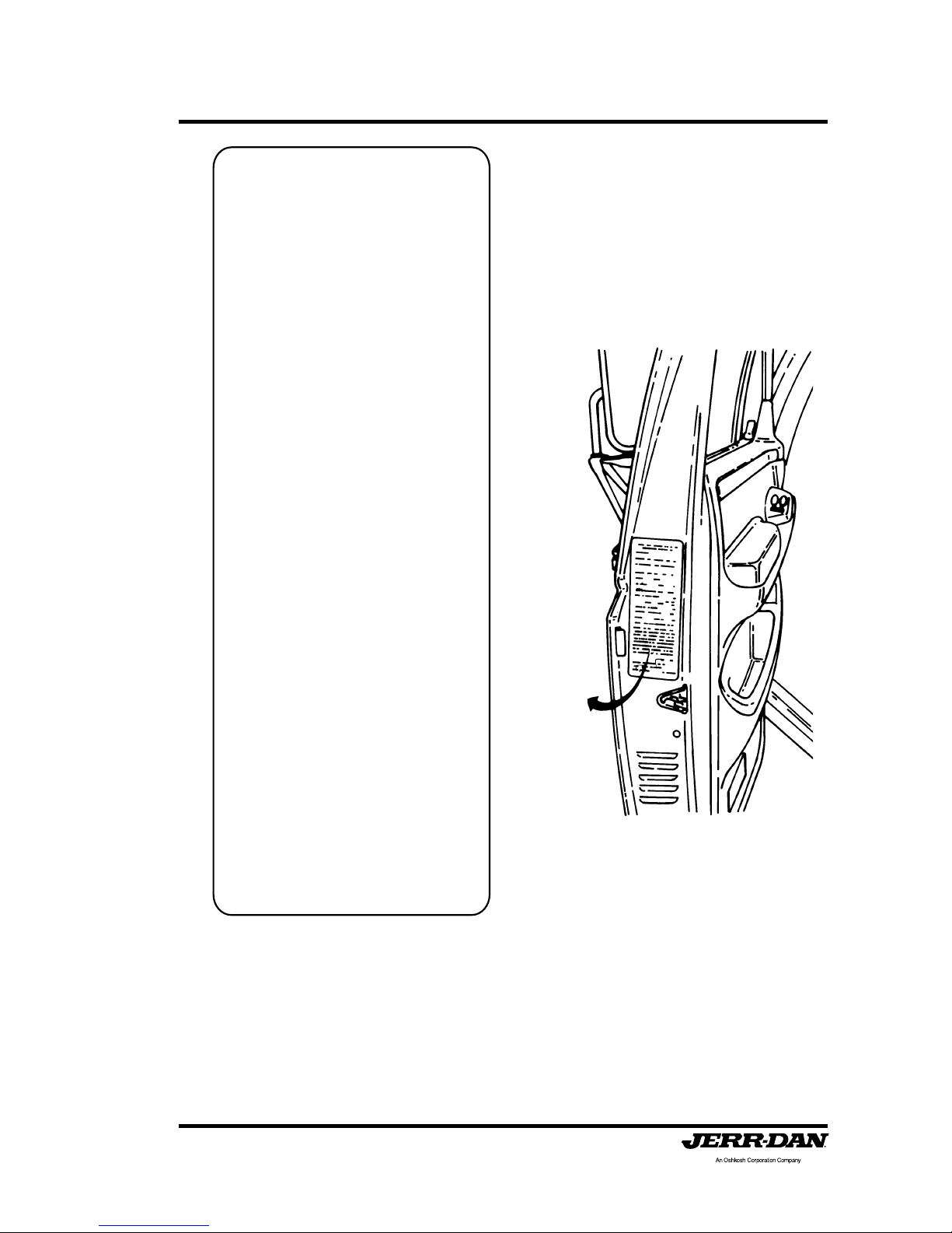
When inquiring about operation, maintenance or warranty, please refer to
your equipment’s Sales Order Number , Serial Number and Model Number .
This information can be found on the aluminum tag riveted inside the driver’s
side toolbox on the back wall in the upper right corner .
001
001
VEHICLE
IDENT. NO.
MODEL NO.
SERIAL NO.
MANUFACTURED BY
GREENCASTLE, PENNSYLVANIA
An Oshkosh Truck Corporation Company

5-376-000086
REV. 4 - 07/10
Jerr-Dan Corporation strives to provide information that is accurate, complete and useful. All information contained in this manual is as accurate as
known at the time of publication and is subject to change, without notice, as
a result of continuous product improvements. Jerr-Dan reserves the right to
amend the information in this document at any time without prior notice.
Should you find inadequacies in the text, please send your comments to the
following address:
Jerr-Dan Corporation
Attn: T echnical Publications
1080 Hykes Road
Greencastle, P A 17225
Additional or replacement manuals or replacement safety warning labels
can be ordered by calling Jerr-Dan Parts at 717-597-71 1 1. Price and availability will be quoted at time of the request.
The material in this document is confidential and the property of Jerr-Dan
Corporation. No part of this document may be photocopied, reproduced or
translated to another language without the express written consent of JerrDan Corporation.
Manufactured under one or more of the following patents: 5,575,606;
5,672,042; 5,697,741; 5,713,714; 5,722,810; 5,782,596; 5,839,755; and
6,315,515 B1 with other Patents Pending.
Jerr-Dan and the Jerr-Dan logo are registered trademarks and Run Hard is a
service mark of Jerr-Dan Corporation, Greencastle, P A. USA

5-376-000086
REV. 4 - 07/10
Page i
LIMITED WARRANTY
Manufacturer's Warranty. Manufacturer's sole warranty shall be the following, which
Distributor shall make on behalf of Manufactuer by conspicuous notice in writing
accompanying each contract or memorandum of sale:
1. Warranty. Jerr-Dan Corporation, ("Manufacturer") warrants each new product made
by it to be free from defects in material or workmanship for one year from the date of
initial sale, lease, rental, or other disposition of such product, and agrees only to repair or
replace at its own expense, f.o.b. the place or places of manufacture, at manufacturer's
option, any part or parts of the product found to be defective in material or workmanship,
provided Manufacturer is notified of such defect or defects within the one year warranty
period and given a reasonable time to correct the defect. In no case, shall the warranty
extend to defects in materials, components, or services furnished by third parties. Defects
caused by chemical action, or the presence of abrasive materials and defects arising
following the operation beyond rated capacity or the improper use or application of any
Products shall not be considered defects within the scope of the foregoing warranty. If any
repairs or alterations are made or any parts are replaced during the period covered by any
warranty above mentioned by other than an authorized Manufacturer's Distributor in
accordance with authorized Manufactuerer's service manuals or with other than parts,
accessories, or attachments authorized by Manufacturer for use in its products, customer
shall pay for all such repairs or parts without recourse against Manufacturer, and Manufacturer
shall be relieved of responsibility for fulfillment of this warranty with respect to parts or
components of all repairs, alterations or replacements so made. No claims for labor shall
be considered unless authorized by Manufacturer.
2. Disclaimer as to Consequential or Special Damages. Under no circumstances
shall Manufacturer be liable for any consequential or special damage which any person,
firm, corporation, or other entity may suffer or claim to suffer or incur or claim to incur as
a result of any defect in the product or in any correction or alteration thereof made or
furnished by Manufacturer or others. "Consequential" or "special damages" as used herein
includes but is not limited to costs of transportation, lost sales, lost orders, lost profits,
lost income, increased overhead, labor and material costs and cost of manufacturing
variances and operational inefficiencies.
3. Maximum Liability. The maximum liability of Manufacturer under the exclusive
warranty set forth herein shall be the amount paid to Manufacturer by the vendor of the
component with respect to the product to which such vendor warranty applies.
4. Limitation of Liability. The limitation of liability provisions herein shall apply to
any and all claims or suits brought against Manufacturer, including any claim based upon
negligence, breach of contract, breach of warranty, strict liability or any other theories
upon which liability may be asserted against Manufacturer.
1080 Hykes Road
Greencastle, P A 17225
(717) 597-71 1 1
WARRANTY

5-376-000086
REV. 4 - 07/10
Page ii
5. Exclusive and Entire Warranty. The warranty constitutes Manufacturer's entire
warranty as to the product and it is expressly agreed that the remedies of dealer and those
claiming under dealer as stated in this warranty are exclusive. Manufacturer does not
assume (and has not authorized any other person to assume on its behalf) any other
warranty or liability in connection with any product covered by this warranty.
MANUFACTURER EXPRESSLY DISCLAIMS ANY AND ALL OTHER WARRANTIES OF
ANY KIND WHA TSOEVER AS T O THE PRODUCT FURNISHED HEREUNDER, INCLUDING
BUT NOT LIMITED T O EXPRESS OR IMPLIED W ARRANTIES AS T O MERCHANT ABILITY,
FITNESS FOR PARTICULAR PURPOSES SOLD, DESCRIPTION OR QUALITY OF THE
PRODUCT FURNISHED HEREUNDER.
6. Notice of Occurrence. This warranty shall be void if, upon the occurrence of any
incident involving any product made by Manufacturer, and resulting in any personal injury
or property damage, customer shall fail to notify Manufacturer within 24 hous of such
occurrence or permit Manufacturer audit representatives to have immediate access to
such product and to all records of and within the control of the customer and/or distributor
relating to the product and the occurrence.
7. Filing of Warranty Claim. Upon notifying the Manufacturer of a failure, the
Manufacturer or its representative will verbally authorize and comfirm by letter the repairs
to be made. Verbal authorization will require the following information:
A) Owner's name and telephone number.
B) The dealer's name from whom it was purchased.
C) The Manufacturer's unit serial number.
D) Telephone number of the party making the repairs.
E) The part numbers needed to make repairs.
F) Owner to be informed of C.O.D. on parts (if deemed necessary) to assure return of
defective parts for manufacturer’s evaluation.
At this time, the Manufacturer will ship as soon as practical the parts needed to make the
repair. Included with the parts will be the invoice for the parts and a Request for Warranty
form, with the Warranty Return Tags.
The vehicle owner/dealer will complete the Request for Warranty form and the Warranty
Return Tag marked "Return with Shipping Notice." Both documents should be attached to
the shippping notice and returned to the Manufacturer by mail. The parts to be returned
shall be tagged with the Warranty Return Tag (more than one part pertaining to the same
warranty claim shall be identified with the same warranty claim number - see number on
Warranty Return Tag). All parts under this claim shall be returned to the Manufacturer prepaid for warranty evaluation.
Upon receiving the part or parts for warranty evaluation, the part will be inspected and
tested. After being inspected and tested, the decision to honor or deny warranty claim shall
be based on analysis of all available information.
When warranty is honored, the Manufacturer will reimburse the owner/dealer in the amount
agreed to by both parties.
If warranty is denied, the owner and distributor will be notified in writing of the decision and
a full explanation for the decision will be given.
8.Manufacturer may at any time amend the foregoing form of warranty without prior
notice.

5-376-000086
REV. 4 - 07/10
Page iii
TABLE OF CONTENTS
Section I: Safety
Safety (General).......................................................................1
Ratings: MPL40 .......................................................................3
Safety Chains ..........................................................................8
Lift Safety ................................................................................9
Boom Safety .......................................................................... 1 0
Sling Safety ........................................................................... 14
Safety Warning Decals .......................................................... 16
Section II: Operation
Wheel -Lift .............................................................................1 9
Tie-Down S traps.....................................................................25
Wheel Grid Sp acers ............................................................... 2 8
T owball Hitch Attachment.......................................................29
Wrecker Boom - Single Line Boom - Worm Gear Winch ....... 31
Wrecker Boom - Single Line Boom - Planetary Gear Winch ..3 7
Wrecker Boom - Dual Line Boom - Worm Gear Winches ...... 4 2
T ow Sling (Optional) ...............................................................48
Motorcycle T owing Adapter (Optional) .................................... 58
Dolly S torage (Optional) ......................................................... 65
Dollies (Optional) ...................................................................70
Section III: Maintenance
Maintenance and Lubrication ................................................. 73
Oils and Greases ................................................................... 76
Wire Rope Handling and Inspection ....................................... 77
Underlift Level S top Assist System ........................................ 79
Lubrication Points .................................................................. 80
Trouble Shooting ....................................................................81
Hydraulic System .................................................................. 81
Hydraulic Clutch Pump .......................................................... 82
P.T .O. Functioning Improperly ................................................83
Hydraulic Pump ..................................................................... 83
Winch Functioning Improperly................................................84
Section IV: Glossary
Glossary ................................................................................85

5-376-000086
REV. 4 - 07/10
Page iv
THIS P AGE INTENTIONALL Y LEFT BLANK

Section I: Safety
Page 1
5-376-000086
REV. 4 - 07/10
The safe operation of your MPL40 is your responsibility . Read this manual
and the truck manufacturer’s manual and thoroughly understand them. Y ou
can be held legally responsible for injuries or damage resulting from unsafe
operating practices.
Our recommendations for operating your equipment can help you avoid
unsafe practices and their bad consequences. These recommendations
are contained in this manual.
Jerr-Dan Corporation is not responsible for the results of any unsafe practice
of tow operators or for the failure of your equipment or its accessories resulting
from improper use or maintenance.
The danger from a vehicle continues after it is disabled or wrecked.
Recovering or towing vehicles can be dangerous too! The danger threatens
tow operators and everyone else close by. As a tow operator you must
develop an awareness of the hazards involved. Y ou must use every safeguard
within reason to prevent injuries.
Careful consideration of the immediate surrounding conditions such as the
weather, terrain, type or condition of the vehicle to be recovered and the
condition and experience of the operator is foremost to the safety and
success of the operation.
Tie-down straps are provided for use with your new Jerr-Dan Recovery V ehicle.
Periodically inspect all straps for any signs of fatigue or damage. Don’t
overlook the hooks; be sure they have not been bent or deformed. If strap or
hook damage is noted, they must be replaced before being used.
Wire rope cables wear out or can become damaged. Periodically inspect
the wire rope cable for any signs of fatigue or damage. Don’t overlook the
hooks; be sure they have not been bent or deformed. Refer to the Wire
Rope Handling and Inspection Section.
For each step in operating your equipment develop the habit of asking yourself
"is it safe to proceed?" Carefully check your set up before starting a lift or
tow.
Because recoveries can be so different, we cannot warn you of all the possible
dangers you will encounter , but we will tell you of the most common hazards
that we know about. We also recommend that you receive specialized and
advanced training from a professional T owing and Recovery instructor before
SAFETY

Section I: Safety
Page 2
5-376-000086
REV. 4 - 07/10
operating any recovery equipment and that the V ehicle Manufacturers T owing
Manual and/or American Automobile Association (AAA) T owing Manuals be
used as a reference for operating safety methods.
AAA address and phone number:
THE AMERICAN AUTOMOBILE ASSOCIA TION
1000 AAA Drive
Heathrow, FL 32746-9970
(800)222-4357
T o alert personnel to hazardous operating practices, safety messages are
used throughout the manual. Each safety message contains a safety alert
symbol and a signal word to identify the hazard's degree of seriousness.
CAUTION:
Identifies when a potentially hazardous situation exists and may
result in a minor or moderate injury or property damage.
W ARNING:
Identifies when a potentially hazardous situation exists and could
result in death or serious injury .
DANGER:
Identifies when an imminently hazardous situation exists and can
result in death or serious injury .

Section I: Safety
Page 3
5-376-000086
REV. 4 - 07/10
DO NOT EXCEED THE FOLLOWING RA TINGS:
MPL40 Underlift Rating ....................................... 4,000 lbs “L” Arm
2
T ow Rating ..................................................................... 7,500 lbs.
2
Boom Rating: (Extended)...............................................6,000 lbs.
(Retracted) ............................................16,000 lbs.
Winch Rating: (Ramsey Worm Gear Winches)
1
.....................
8,000 lbs.
(Warn Planetary Gear Winch)
1
.........................
9,000 lbs.
Wire Rope:
Working Limit ................................................4,100 lbs.
Construction ............................ 6 x 25 EIPS RRL IWRC
Diameter ........................................................... 3/8 inch
S tandard Length ..............................................100 Feet
1
SAE J706: Surface V ehicle Recommended Practices - Rating of Winches
2
SAE J2512: Surface Vehicle Recommended Practices - Towing
Equipment Ratings and Practices
MAXIMUM LIFTING CAP ACITY - THE MAXIMUM LOAD THA T CAN BE LIFTED.
GROSS COMBINED WEIGHT RA TING (GCWR) - THE V ALUE SPECIFIED BY THE VEHICLE
MANUFACTURER AS GCW.
GROSS COMBINED WEIGHT (GCW) - ACTUAL WEIGHT OF THE ENTIRE VEHICLE A T THE
GROUND WITH TRAILER OR TRAILERS, INCLUDING VEHICLE EQUIPMENT, DRIVER, PASSENGER, FUEL AND P A YLOAD (EVERYTHING THA T MOVES WITH THE VEHICLE).

Section I: Safety
Page 4
5-376-000086
REV. 4 - 07/10
NOTE
These ratings apply to the structural design of the Standard Duty Carrier only
and may be limited by the axle rating and gross vehicle weight rating of the truck
chassis.
The payload and towing capacity of any towing vehicle must meet the
following:
- The actual payload on the towing vehicle must not exceed the posted
rating and, if applicable, the towed vehicle load must not exceed
the posted lift / towing ratings.
- The total weight of the towing vehicle (cab chassis, body, payload,
driver, passenger(s), tools, fuel, etc.) and, if applicable, the towed
vehicle load must not exceed the GVWR (Gross Vehicle Weight Rating)
of the towing vehicle.
- The total weight of the towing vehicle and, if applicable, the towed
vehicle load must be distributed so that each axle’s GAWR (Gross Axle
Weight Rating) is not exceeded.
- The total weight of the towing vehicle and towed vehicle (everything
that moves with the towing vehicle) must not exceed the GCWR
(Gross Combination Weight Rating) of the towing vehicle.
Staying within these ratings is necessary to maintain the safety and
performance of the towing vehicle.
CHECK TRUCK MANUAL FOR SPECIFIC GVW & AXLE RATINGS. ALSO
REFERENCE THE CERTIFICA TION DECAL AFFIXED T O DRIVER’S SIDE DOOR
JAMB, HINGE PILLAR OR LA TCH POST AND THE S.T.A.R. PLACARD ON THE
DRIVER'S SIDE OF THE HEADBOARD.
Section I: Safety
Page 5
5-376-000086
REV. 4 - 07/10
Certification Decal
Affixed to the Driver's Side DoorJam, Hinge Pillar or Latch Post
Provided by the Final St age Vehicle Manufacturer according to Title 49
Part 567 of the Code of Federal Regulations (CFR)
MFG BY:_______________________________________
______________________________________________
DATE OF MFR:MO______________YR.______________
GVWR:_________________KG (_________________LB)
GAWR-FRONT:
______________________KG (__________________LB)
WITH____________________________________TIRES,
______________________RIMS,@______________KPA
(___________________PSI) COLD__________________
GAWR-INTERMEDIATE(1):
______________________KG (__________________LB)
WITH____________________________________TIRES,
______________________RIMS,@______________KPA
(___________________PSI) COLD__________________
GAWR-INTERMEDIATE(2):
______________________KG (__________________LB)
WITH____________________________________TIRES,
______________________RIMS,@______________KPA
(___________________PSI) COLD__________________
GAWR-REAR:
______________________KG (__________________LB)
WITH____________________________________TIRES,
______________________RIMS,@______________KPA
(___________________PSI) COLD__________________
MO._______________________YR._________________
VEHICLE IDENTIFICATION NUMBER:
_______________________________________________
VEHICLE TYPE:
_______________________________________________
THIS VEHICLE HAS BEEN COMPLETED IN ACCORDANCE WITH
THE PRIOR MANUFACTURERS' IVD, WHERE APPLICABLE.
THIS VEHICLE CONFORMS TO ALL APPLICABLE FEDERAL
MOTOR VEHICLE SAFETY STANDARDS, [AND BUMPER AND
THEFT PREVENTION STANDARDS, IF APPLICABLE] IN EFFECT IN:

Section I: Safety
Page 6
5-376-000086
REV. 4 - 07/10
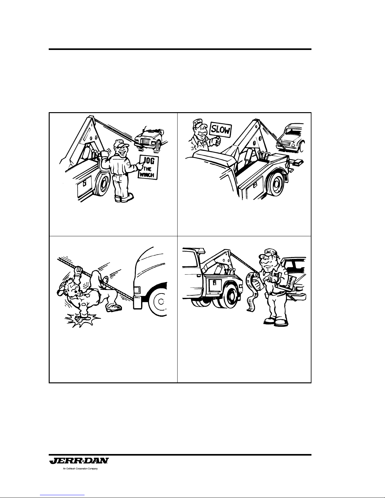
• Don’t use a recovery vehicle that has not
been properly maintained. Pay special
attention to the mounting bolts, and
lubrication of moving parts.
• Don’t operate the wrecker’s engine faster than
recommended. Excessive speeds can
damage PTO, hydraulic pumps, and winches.
• Don’t pick-up and tow a vehicle that reduces
the weight on the front wheels of the wrecker
more than 50 percent.
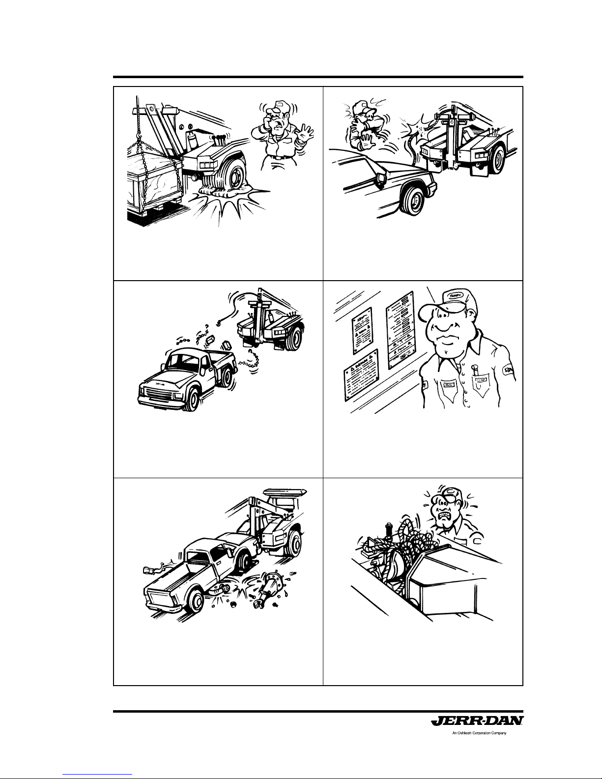
• Don’t travel with the PTO or Clutch Pump
engaged. Damage to the trucks transmission,
engine or hydraulic components will occur.
Engage it only while operating the controls.
• After you have hooked up a vehicle for
towing, don’t start the tow until you have
double checked the hook-up, installed safety
chains, and released the parking brakes of
the towed vehicle.
• Don’t operate the wrecker’s engine faster than
recommended. Excessive speeds can
damage PTO, hydraulic pumps, and winches.
• Don’t rely on anti-theft steering locks to secure
the steering wheel. Use a special steering
wheel clamping device designed for this
purpose.

Section I: Safety
Page 7
5-376-000086
REV. 4 - 07/10
• Don’t tow a vehicle on its front wheels
unless the steering wheel is secured with
the front wheels straight ahead.
• Don’t tow a vehicle on its front wheels if
they are damaged.

Section I: Safety
Page 8
5-376-000086
REV. 4 - 07/10
SAFETY CHAINS MUST BE USED WHEN TOWING
AND TRANSPORTING
Safety chains are provided for use with your new Jerr-Dan Recovery V ehicle.
Periodically inspect all chains for any signs of fatigue or damage. Don’t
overlook the hooks; be sure they have not been bent or deformed. If chain or
hook damage is noted, they must be replaced before being used. Do not
use safety chains for recovery operations.
Many states require that the towed vehicle be secured to the wrecker body
with safety chains. Check your local regulations and use your safety chains.
Safety chains are provided for use with your new JERR-DAN.
• Never attach the chain hooks in such a
way as to damage brake lines or other
functional parts.
• Keep in mind that driving over bumps and
hollows and around corners will tend to
tighten or loosen the chains.
• Check that the chain does not become over
tensioned when raising the towed vehicle to the
towing position or during the towing operation.
• Always use two safety chains when towing all
vehicles, regardless of distance.

Section I: Safety
Page 9
5-376-000086
REV. 4 - 07/10
LIFT SAFETY
Careful consideration of the immediate surrounding conditions such as the
weather, terrain, type or condition of the vehicle to be recovered and the
condition and experience of the operator is foremost to the safety and
success of the operation. In addition, the intent of the design of this unit
should be taken before the undertaking of its use.
Your MPL40 is unique. It not only can make lifts from level surfaces, our
boom tilt feature allows pickup of vehicles that are parked on both inclines
and declines.
• You should never make a lift or movement
while close to or under the vehicle being
lifted!
• Always use jack stands to support the vehicle
if it is necessary to work under it.
• Towing lights are required in many areas and are always recommended for safe
tows.
Section I: Safety
Page 10
5-376-000086
REV. 4 - 07/10
• Jog the winch control lever to be sure of
complete engagement of the clutch gears
before making a lift or pull.
• Never stand on or straddle a working wire
rope.
• Take up the wire rope slowly and be sure
the hook is securely set.
• Be sure of your lift or pull and do not exceed
the working strength of the wire rope or hook.
Rig to keep the estimated amount of pull
well within equipment ratings. Use wire rope
breaking strength ratings only for selecting
replacement wire rope.
BOOM SAFETY
Your MPL40 is equipped with a recovery winch and the following safety
procedures must be observed:

Section I: Safety
Page 11
5-376-000086
REV. 4 - 07/10
• Never lift or pull over or around a sharp obstacle.
• Never completely unwind wire rope from a
winch while loaded. Always be sure that a
minimum of five (5) wraps of wire rope are on
the drum at all times.
• Never tie down the front end of your wrecker
for recovery work of heavy lifts. You will
likely damage the truck frame if you do.
• Never allow the wire rope to cross wrap
(criss-cross) on the winch drum. Crushing
of the wire rope can cause wire rope failure.
• Never make a lift or pull with the wire rope
attached to light gauge or sheet metal parts;
use the frame or major structural members.
• Don’t disengage the winch drum clutch while
the wire rope is loaded.

Section I: Safety
Page 12
5-376-000086
REV. 4 - 07/10
• Don’t permit bystanders in the area while
performing recovery work.
• Never wrap the wire rope around frames or
cross members. Use chains and hook the
wire rope to the chains.
• Don’t use damaged wire ropes on your
wrecker. Become familiar with the various
types of wire rope damage and periodically
inspect the entire wire rope for wear and
corrosion. Never use wire rope menders.
Replace with similar rated wire rope and
hooks.
• Be sure all brakes and locks are properly
set on the recovery vehicle.
• Never under any circumstances use the
winch or boom to lift people!
• Lubricate and maintain both the wire rope
and winch on regular intervals. (See
maintenance charts.)
Section I: Safety
Page 13
5-376-000086
REV. 4 - 07/10
• All boom placement functions should be
made with the winch wire ropes set in “free
spool” to avoid over tensioning or breaking
the winch wire ropes.
• Avoid using the boom raise or boom up
control to lift a load. This causes undue
stress and weight loading on the rear axle.
Use the winch to lift the load.
• After rigging wire ropes, don’t begin pulling
without rechecking connections. Make sure
that all wire ropes and snatch blocks are
securely attached and cannot accidently
pull loose.
• Don’t tow a vehicle on its drive wheels unless
steps have been taken to protect its
transmission and differential. Follow the
recommendations of the vehicle manufacturer. As an alternative, use a towing
dolly.
• To avoid birdnesting and premature failure
of the wire rope, always keep tension on
the wire rope when unwinding.
• Don’t exceed ratings of booms, wire ropes,
snatch blocks, or winches. Stay within
nameplate ratings.

Section I: Safety
Page 14
5-376-000086
REV. 4 - 07/10
• Hook up and make the lift in strict
accordance with AAA’s instructions.
• Never attach the chain hooks in such a
way as to damage brake lines or other
functional parts.
• Be sure the chains and hooks are attached
to frame members and not sheet metal.
• Never make a front lift without unlatching
the hood of the vehicle.
SLING SAFETY
If your MPL40 is equipped with an optional tow sling certain safety
precautions must be taken to ensure safe operation. Consult the AAA
Towing Manual for the make and model of the vehicle to be towed and
observe the following safety procedures:

Section I: Safety
Page 15
5-376-000086
REV. 4 - 07/10
• The bottom anchor assembly (round tube) must never be higher than the attachment point on
the rear of the MPL40. The rear stand off bar assembly acts as a pivot in the event of a
sudden stop. This will asure that the casualty vehicle will not catapult forward onto the deck of
the recovery vehicle.

Section I: Safety
Page 16
5-376-000086
REV. 4 - 07/10
CAUTION
424
424
TOWHITCHBRACKET
MUST BE REMOVED
BEFORE UNFOLDING
THEBOOMDOWNFOR
WHEEL GRID OPERATION
TOW HITCH BRACKET
MUST BE REMOVED
BEFORE UNFOLDING
THE BOOM DOWN FOR
WHEEL GRID OPERATION
SAFETY WARNING DECALS
As an extra safety precaution, your MPL40 has specific safety and warning
decals affixed to prominent locations. These decals must not be obliterated,
removed or painted over . They are there to remind and protect the operator .
CAUTION
034
CHECK HYDRAULIC FLUID LEVEL
FILL ONLY WITH APPROVED FLUID
(SEE OPERATOR'S MANUAL)
T
WARNING
122
122
TOWED VEHICLE MUST BE
CONNECTED TO TOW TRUCK BODY
WITH SAFETY CHAINS
TOWED VEHICLE MUST BE
CONNECTED TO TOW TRUCK BODY
WITH SAFETY CHAINS
546
A MINIMUM OF 5 WRAPS OF CABLE MUST
BE LEFT
O
N WINCH DRUM TO ACHIEVE
RATED L
OAD.
DO NOT USE WINCH TO MOVE OR LIFT
PERSONS.
WARNIN
G
WARNING
WARNING
036
036
VEHICLE MUST BE SECURED TO WHEEL
GRID USING BOTH TIE DOWN STRAPS
PRIOR
TO LEAVING LOADING
SITE
VEHICLE MUST BE SECURED TO WHEEL
GRID USING BOTH TIE DOWN STRAPS
PRIOR
TO VING LOADING

Section I: Safety
Page 17
5-376-000086
REV. 4 - 07/10
BODY NO:
SERIAL NO:
TOW RATING: LBS. (MAXIMUM)
UNDER LIFT NO:
UNDER LIFT CAPACITY: LBS. *
VIN C.A. IN.
* NOTE: LIFT CAPACITY INDICATES THE
STRUCTURAL CAPACITY OF THE LIFT MECHANISM,
NOT THE MAXIMUM EFFECTIVE TRANSPORT LOAD.
REAR AXLE WEIGHT RATING (GAWR): LBS.
TRUCK CHASSIS INFORMATION
THE MAXIMUM EFFECTIVE TRANSPORT LOAD OF
THIS UNIT BASED ON TRUCK CHASSIS
G.A.W.R. AND G.V.W.R SPECIFICATIONS
DO NOT EXCEED THE FOLLOWING WEIGHTS
LBS. AT FULL EXTENSION
LBS. AT 10” EXTENSION
LOSS OF VEHICLE CONTROL, WHICH COULD RESULT
IN SERIOUS BODILY INJURY OR DEATH, CAN OCCUR
IF THE EFFECTIVE TRANSPORT LOAD IS EXCEEDED.
MAXIMUM EFFECTIVE TRANSPORT LOAD IS AFFECTED BY THE CHASSIS
ON WHICH THE TOWING EQUIPMENT IS INSTALLED. BEFORE
ATTEMPTING TO USE THIS EQUIPMENT ON A CHASSIS OTHER THAN
THAT SPECIFIED ABOVE, CONTACT JERR-DAN TO OBTAIN
A REVISED RATING.
SAFETY IS NO ACCIDENT.
REVIEW OPERATOR’S PRE-TRANSPORT CHECKLIST IN THE OWNER’S
MANUAL EACH TIME YOU MOVE A VEHICLE. FOLLOW ALL
INSTRUCTIONS ON CONTROLS AND UNIT.
© COPYRIGHT 1999
JERR-DAN CORPORATION
307
Hazardous voltage.
Will cause severe
injury or death.
Hazardous voltage.
Will cause severe
injury or death.
Do not raise, lower
or move boom within
near power lines.
Do not raise, lower
or move boom within
near power lines.
203
203
DANGER
DANGER
WARNING
037
MOVING PARTS
KEEP HANDS AND FEET CLEAR
OF THIS AREA

Section I: Safety
Page 18
5-376-000086
REV. 4 - 07/10
THIS P AGE INTENTIONALL Y LEFT BLANK

Section II: Operation
Page 19
5-376-000086
REV. 4 - 07/10
WHEEL-LIFT OPERATION
Your MPL40 is one of the most useful and efficient towing and recovery
vehicles available. It is hydraulically powered and careful consideration should
be given to the selection of commands. You can afford to work smart, the
vehicle will do most of the work for you.
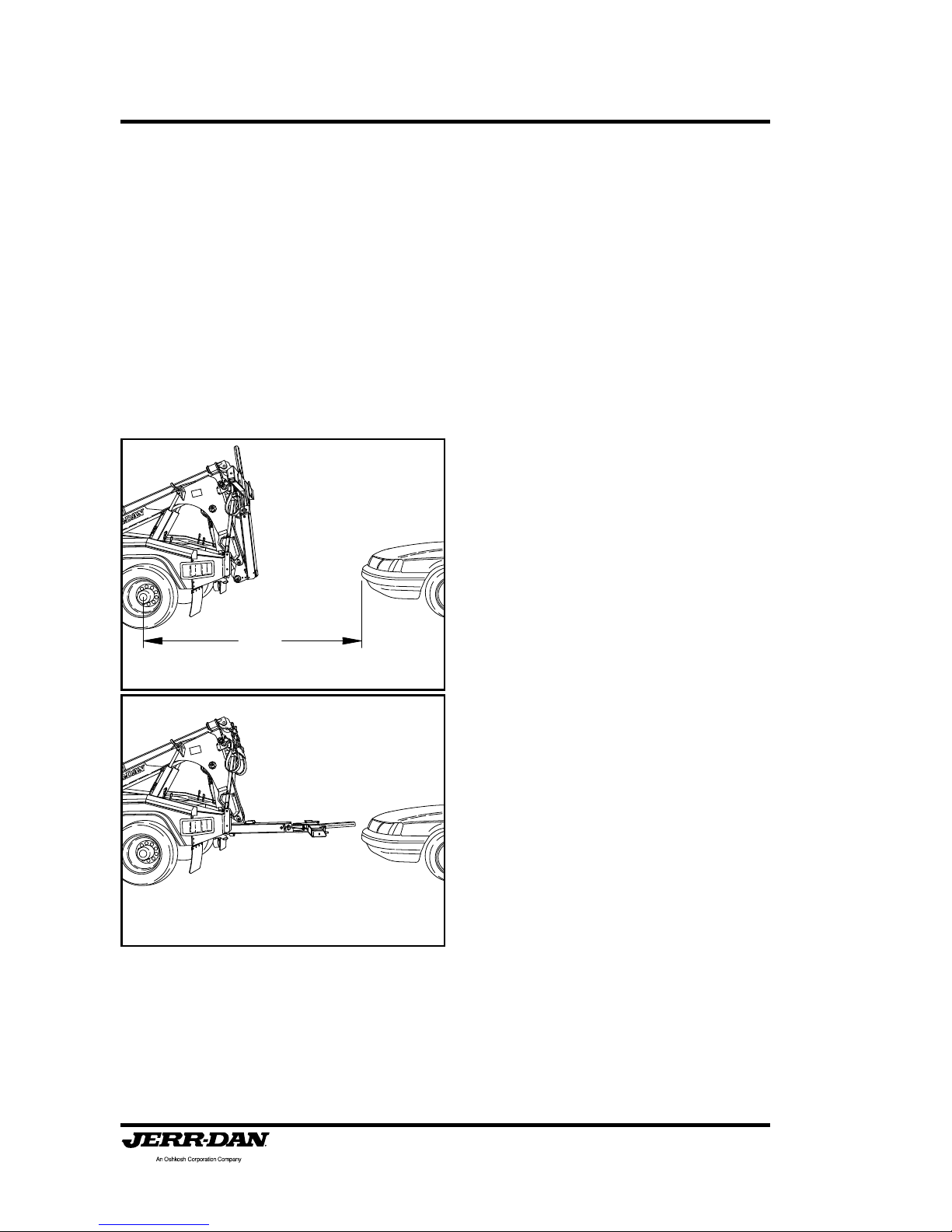
Follow these simple steps:
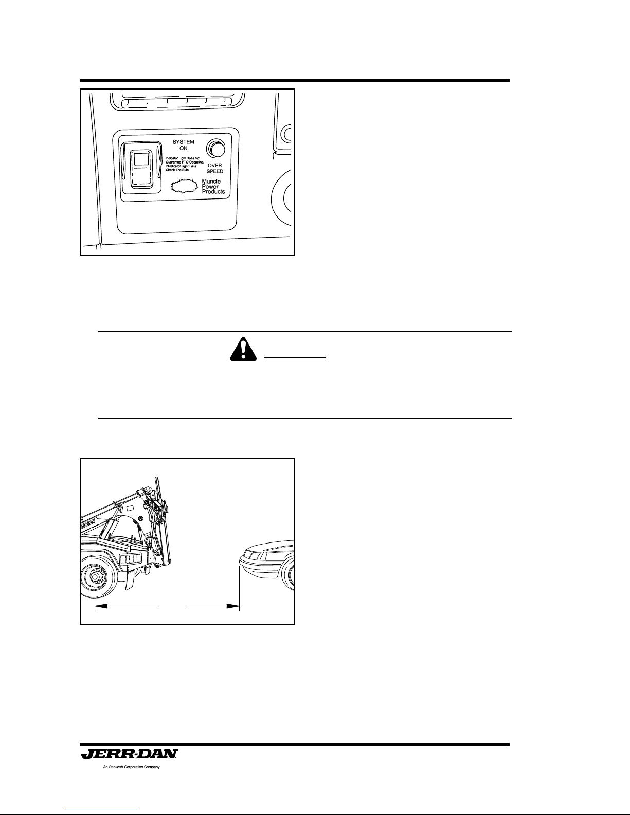
1. Turn on the safety and work
lights. (Switches located on the
dash panel).
2. Position the truck within 9 ft. of
the subject vehicle and as close
to the direction of the pull as
possible.
3. Set the truck’s parking brakes
and put the transmission in park
or neutral.
9 FT
OPERATION
Section II: Operation
Page 20
5-376-000086
REV. 4 - 07/10
4. Engage the Power-Take-Off
(PTO) or Clutch Pump and the
hand controller using the “Control”
switch in the switch panel. Most
trucks will automatically throttle
up when the parking brake is set
and the transmission is park or
neutral. NEVER TRAVEL WITH
THE POWER-TAKE-OFF or
CLUTCH PUMP CONTROL
ENGAGED. This could result in
damage to the PTO or Clutch
Pump unit and the truck
transmission.
CAUTION:
Never exceed 1,500 R.P.M. When your hook up is complete, reset
the engine idle to normal.
5. Confirm the truck’s position in
relation to the vehicle to be towed.
Nine (9) feet is recommended.
Reposition the MPL40 if
necessary. Be sure the towed
vehicle is not in gear or park.
Keep the brake set.
9 FT

Section II: Operation
Page 21
5-376-000086
REV. 4 - 07/10
6. Using the hand controller or
manual controls located at the
rear of the body, unfold the
underlift using the tilt down
function. The underlift level stop
assist system will stop the
underlift travel at a preset position.
7. Next, lower the underlift using the
underlift down funtion on the hand
controller . The underlift level stop
assist system will stop the
underlift travel at a preset position
about 1-1/2" to 2” from the ground.
NOTE:
To override either stop
position, simply release the
control function and
reactivate the same control
function again to achieve
further travel of the underlift.

Section II: Operation
Page 22
5-376-000086
REV. 4 - 07/10
8. Extend the underlift under the
vehicle being sure that all under
carriage parts are cleared and that
the front portion of the grid is in
contact with both tires. Lower the
grid fully to the ground. There is
no reason for the operator to
get under the vehicle.
9. Visually inspect the tire to grid
contact before proceeding.
10. Close the grid arms around the
tires to secure the towed vehicle.
Make sure that the arm is fully
closed and in its over center
locked position.
11. After securing the grid arms
around the towed vehicles tires
and before making the actual lift,
check to be sure the towed
vehicle’s parking brake is
released, the transmission is in
neutral, and the wheels are
straight.
NOTE:
If vehicle to be towed is on a
slope, do not release the
brake until the tie-down
straps are installed. Observe
the wheels in the grid for any
slippage.
12. It is recommended that the
steering wheel be secured by a
steering wheel strap for any tow.

Section II: Operation
Page 23
5-376-000086
REV. 4 - 07/10
13. Lift the vehicle high enough to
allow the tires to clear the ground.
Make sure that the grid is not in
contact with any engine or body
components.
14. Remove the tie down straps from
tool boxes and attach the tie
down straps. (See Tie-Down
Strap instructions).
15. With the straps in place, the
vehicle in neutral and the parking
brake released, you can move the
vehicle safely up, down, in or out.
All of these movements are
hydraulically controlled by the
hand controller .
16. Raise the vehicle into the final
towing position observing the far
end for sufficient ground
clearance. It is possible to set the
rear of a front lifted vehicle
completely onto the ground,
causing damage. Take irregular
roadsurfaces into consideration.
Observe the lift function from the
side and away from both vehicles
if possible.
NOTE:
For the best towing and
maneuverability the boom
should be as close to
horizontal as possible.
Section II: Operation
Page 24
5-376-000086
REV. 4 - 07/10
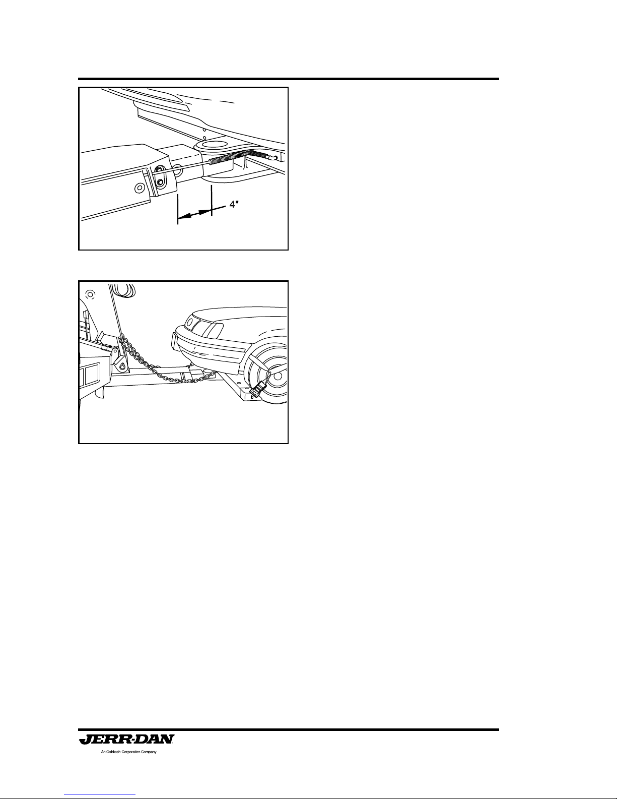
17. Power retract the grid boom until
the towed vehicle is about 3 to 4
feet from the back of the truck.
Leave enough room to maneuver
around corners without corner
binding or causing contact
between the two (2) vehicles. Be
sure that the boom is extended
at least 4" to ensure
unobstructed crossbar
pivoting.
18. Be sure to maintain sufficient
clearances with the bottom of the
towed vehicle.
19. Attach the safety chains and
towing lights. Safety chains
should be crossed from one
side of the recovery vehicle to
the opposite side of the towed
vehicle.

Section II: Operation
Page 25
5-376-000086
REV. 4 - 07/10
TIE DOWN STRAPS
The MPL40 is supplied with a set of high strength polyester web tie down
straps. They are to be used to secure wheels of the towed vehicle to the
wheel lift grid. NEVER TOW A VEHICLE WITHOUT THE TIE DOWN
STRAPS INST ALLED.
The tie down strap assembly is
comprised of 2 basic components:
1. The S trap/Hook Assembly
2. The Ratchet S pool
Mechanism
The following steps should be
followed to properly install the tie
down straps:
USING THE RATCHET SPOOL MECHANISM
1. First the spool must be set into
“free spool”. This is done by
pulling the lock bar out and
swinging the handle upward until
it rests in the free spool notch and
then simply pulling out the
amount of strap required to fit over
the tire.
2. Now pull on the lock bar and move
it downward until it engages the
ratchet teeth on the take up spool.
By pushing and pulling the handle
up and down, the strap will be
wound onto the spool.

Section II: Operation
Page 26
5-376-000086
REV. 4 - 07/10
3. T o release the ratchet, simply pull
on the locking bar, disengaging
the teeth and raise the handle to
the “free spool” position.
INSTALLING THE TIE DOWN STRAP
1. With the vehicle lifted just barely
off the ground, insert the end of
the strap through the sewn loop
on the other end of the strap to
form a loop. Put the loop over
the tire as shown with the strap
resting on the tire at the ten
o’clock and two o’clock positions.
The choker strap should be
across the center of the tire.
2. Place the rear hook of the strap
assembly into a hole on the back
side of the grid arm. Try to use
the hole that is closest to the tire.

Section II: Operation
Page 27
5-376-000086
REV. 4 - 07/10
3. Place the hook of the ratchet into
one of the holes on the front side
of the grid. Again, try to use the
hole that is closest to the tire.
NOTE:
The hole on the outside of the
grid can be used to hook the
ratchet in if you need to clear
body mouldings or wide tires.
4. Take up the slack in the strap by
ratcheting the takeup spool arm.
Continue until the tires show
some compression. Notice that
the strap in the ratchet is
pulling down and forward on
the loop over the tire.
5. Raise the wheel grid to the towing position. RE-TIGHTEN THE
RATCHET PERIODICALLY AS
THE TIRE SETTLES IN GRID
FROM TOWING.
NOTE:
Never tow a vehicle without
tire tie-down straps and
safety chains installed.

Section II: Operation
Page 28
5-376-000086
REV. 4 - 07/10
WHEEL GRID SPACERS
The MPL40 with the self loading grid is supplied with a set wheel grid spacers.
They can be used to pick up a vehicle with small diameter tires or even a
vehicle without wheels and tires.
The following steps should be
followed to properly install the wheel
grid spacers:
1. Slide the back side of the wheel
spacer over the wheel grid arm.
2. Close the grid arms around the
tires to secure the towed vehicle.
Make sure that the arm is fully
closed and in its over center
locked position.
3. Visually inspect the tire to grid
contact before proceeding.

Section II: Operation
Page 29
5-376-000086
REV. 4 - 07/10
TOWBALL HITCH ATTACHMENT
The MPL40 is supplied with a Towball Hitch attachment that will allow you
to recover and tow trailers requiring a tow ball hookup.
DO NO EXCEED THE FOLLOWING RA TINGS:
1-7/8 in. Ball:................................5,000 lbs. (GTW)*
2 in. Ball: .....................................5,000 lbs. (GTW)*
2-5/16 in. Ball:..............................7,500 lbs. (GTW)*
50 MM Ball: .................................5,000 lbs. (GTW)*
* Gross T ongue W eight
1. Remove the towball hitch
attachment from the toolbox.
2. Install the towball hitch to the
bottom on the underlift boom using
the hitch pins.
3. Secure the hitch pins with the
linch pins.

Section II: Operation
Page 30
5-376-000086
REV. 4 - 07/10
4. Install the desired towball to
the towball hitch.
5. Position the ball coupler over
the ball and lock into place.
CAUTION:
Make sure that the ball and
coupler are of the same
matched size.
6. Connect the trailer lights and
attach safety chains.

Section II: Operation
Page 31
5-376-000086
REV. 4 - 07/10
WRECKER BOOM OPERATION
SINGLE LINE BOOM - WORM GEAR WINCH
The MPL40 wrecker boom is an extremely effective tool in recovery or retrieval
prior to lifting and towing. To operate the wrecker boom effectively, care and
thought must be given.
Boom Rating: (Extended) .....................................6,000 lbs.
(Retracted) ..................................16,000 lbs.
Winch Rating: (Ramsey Worm Gear)...................8,000 lbs.
Wire Rope Working Limit: ....................................4,100 lbs.
Wire Rope Construction: ................ 6 x 25 EIPS RRL IWRC
Wire Rope Size:.................................... 3/8 inch x 100 Feet
*All ratings comply with SAE J2512 and SAE J706 Recommended Practice
WARNING:
Do not exceed the working limit of the wire rope. Use snatch blocks
and multiple lines to reduce the load on the wire rope.
1. Check the direction you wish the
work to travel, being sure there
are no major obstacles in the
way.

Section II: Operation
Page 32
5-376-000086
REV. 4 - 07/10
2. Position and align the truck to
obtain as direct a pull as possible.
Straight line pulls are the best and
most efficient.
3. Set the brakes on your Jerr-Dan
unit.
4. Unfold the under lift boom.
5. If a heavy lift or pull is to be made
additional lines may be
necessary. Always use more
stabilizing lines than pull lines.
RIG FOR SAFETY. The use of
scotch blocks is also
recommended.
6. Unhook the wire rope cables from
the top of the tow sling.

Section II: Operation
Page 33
5-376-000086
REV. 4 - 07/10
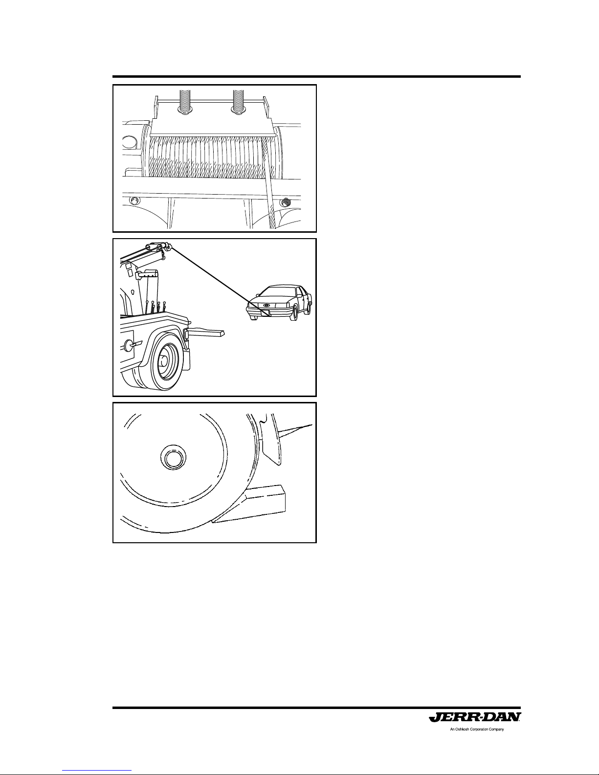
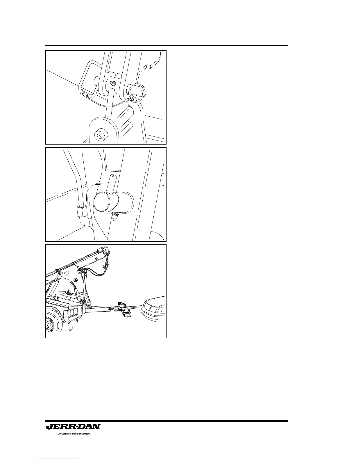
7. Disengage the winch “free-spool”
by pulling out on the “T” handle
and turning the handle 90°. The
handle should remain in the “freespool” position. Never turn this
handle while the wire rope is
under load! This allows the wire
rope to be pulled directly off the
drum to the work.
8. Position the boom head by using
the boom up and down control
lever and the boom in and out
lever .

Section II: Operation
Page 34
5-376-000086
REV. 4 - 07/10
9. Attach the wire rope hook to a
chain sling, or bridle and hook
securely to the work. Be sure of
this hook up; you don’t want it
breaking loose during the pull.
(See the safety sections earlier
in this manual). Do not connect
to thin or loose body panels or
components that could break
loose during the winching
operation. Slings and bridles are
usually designed with hook
clusters on them. Most chassis
manufacturer’s provide tie-down
hooks and/or slots in chassis
frames that may be able to be
used as recovery attachment
points. (Consult the Chassis
Manufacturer’s Towing Manual
and/or the American Automobile
Association (AAA) Towing
Manuals.)
10. Reengage the winch “free-spool”
by turning the handle back 90°.
11. Jog the winch control until the
handle retracts into the engaged
position. Now slowly take up the
slack in the wire rope.
Section II: Operation
Page 35
5-376-000086
REV. 4 - 07/10
12. With the wire rope tight, slowly
wind it in, observing both the work
and the drum. Be sure the wire
rope strands do not cross wrap
or criss-cross on the drum.
Observe the path the work must
travel for snags or obstructions
which could stall the movement
and overload the wire rope.
13. Once the work is in the desired
position, apply the towed vehicles
parking brake or use blocks or tie
the work down if there is any
question about stability. Slowly
reduce the wire rope tension.
After enough wire rope has been
unwound, you may remove the
hookup.
Section II: Operation
Page 36
5-376-000086
REV. 4 - 07/10
14. Now slowly retrieve the wire rope,
carefully winding the wire rope
onto the drum. Many operators
take this opportunity to do a
visual inspection. When you’ve
finished rewinding the wire rope,
be sure you don’t overwind it.
Always wear safety glasses and
gloves when doing recovery work
or handling the wire rope.
Remember, most wire rope failures are caused by cable
crushing or the operator underestimating the pull or over
estimating the wire rope strength.

Section II: Operation
Page 37
5-376-000086
REV. 4 - 07/10
WRECKER BOOM OPERATION
SINGLE LINE BOOM - PLANETARY GEAR WINCH
The MPL40 wrecker boom is an extremely effective tool in recovery or retrieval
prior to lifting and towing. To operate the wrecker boom effectively, care and
thought must be given.
Boom Rating: (Extended) .....................................6,000 lbs.
(Retracted) ..................................16,000 lbs.
Winch Rating: (Warn Planetary Gear) ..................9,000 lbs.
Wire Rope Working Limit: ....................................4,100 lbs.
Wire Rope Construction: ................ 6 x 25 EIPS RRL IWRC
Wire Rope Size:.................................... 3/8 inch x 100 Feet
*All ratings comply with SAE J2512 and SAE J706 Recommended Practice
WARNING:
Do not exceed the working limit of the wire rope. Use snatch blocks
and multiple lines to reduce the load on the wire rope.
1. Check the direction you wish the
work to travel, being sure there
are no major obstacles in the
way.

Section II: Operation
Page 38
5-376-000086
REV. 4 - 07/10
2. Position and align the truck to
obtain as direct a pull as possible.
Straight line pulls are the best and
most efficient.
3. Set the brakes on your Jerr-Dan
unit.
4. Unfold the under lift boom.
5. If a heavy lift or pull is to be made
additional lines may be
necessary. Always use more
stabilizing lines than pull lines.
RIG FOR SAFETY. The use of
scotch blocks is also
recommended.
6. Unhook the wire rope cables from
the top of the tow sling.

Section II: Operation
Page 39
5-376-000086
REV. 4 - 07/10
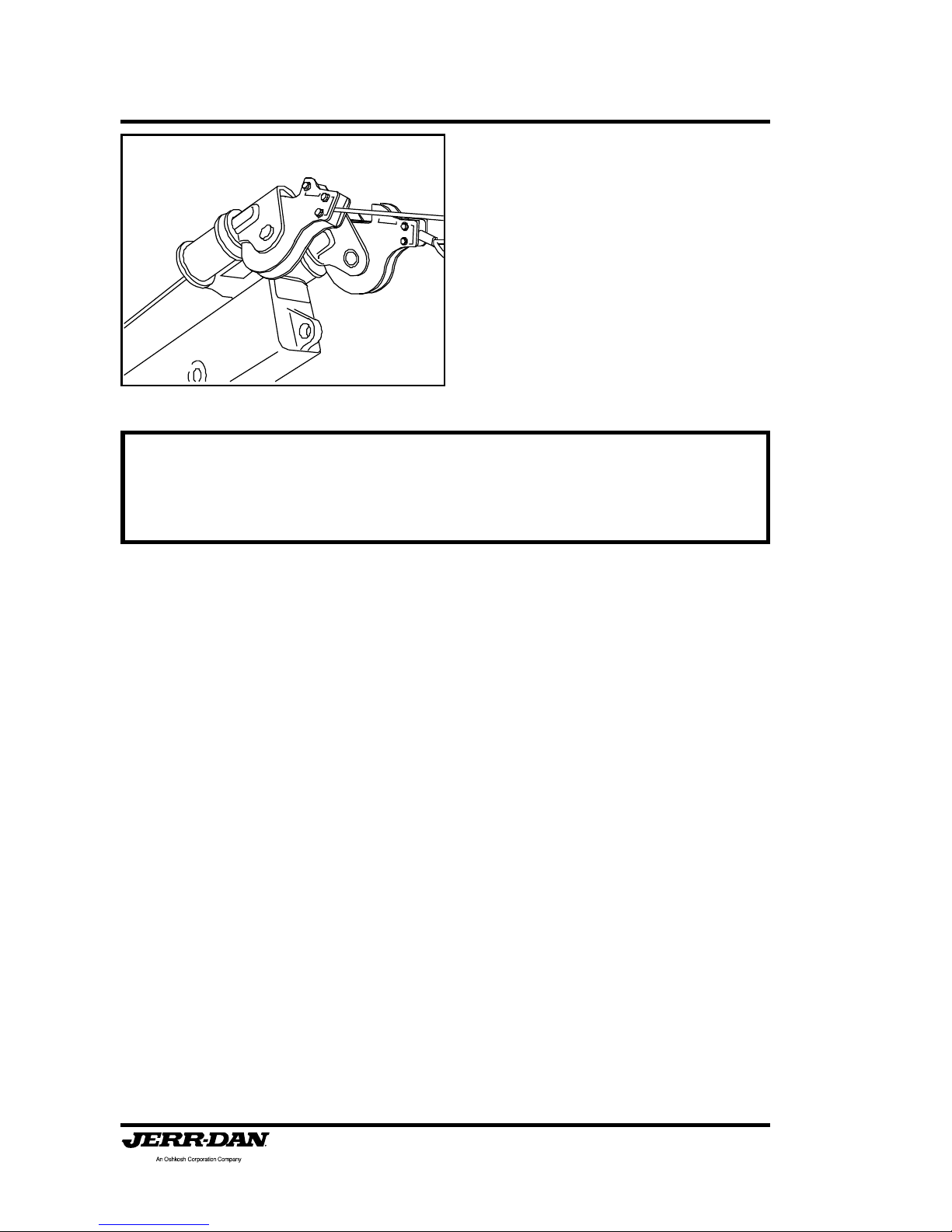
7. Release the free spooling lever
on the winch by pushing down on
the spring steel latch plate and
turning the handle 180°. Never
turn this handle while the wire
rope is under load! This allows
the wire rope to be pulled directly
off the drum to the work. Unwind
enough wire rope to make the
hook-up being sure that a
minimum of at least five (5) wraps
of wire rope remains on the
drums.
8. Position the boom head by using
the boom up and down control
lever and the boom in and out
lever .
9. Attach the wire rope hook to a
chain sling, or bridle and hook
securely to the work. Be sure of
this hook up; you don’t want it
breaking loose during the pull.
(See the safety sections earlier
in this manual). Do not connect
to thin or loose body panels or
components that could break
loose during the winching
operation. Slings and bridles are
usually designed with hook
clusters on them. Most chassis
manufacturer’s provide tie-down
hooks and/or slots in chassis
frames that may be able to be
used as recovery attachment
points. (Consult the Chassis
Manufacturer’s Towing Manual
and/or the American Automobile
Association (AAA) Towing
Manuals.)
Section II: Operation
Page 40
5-376-000086
REV. 4 - 07/10
10. Re-engage the winch drive by
pushing down on the spring steel
latch plate and turning the handle
180°. Confirm winch engagement
by jogging the winch control. Now
slowly take up the slack in the
wire rope.
11. With the wire rope tight, slowly
wind it in, observing both the work
and the drum. Be sure the wire
rope strands do not cross wrap
or criss-cross on the drum.
Observe the path the work must
travel for snags or obstructions
which could stall the movement
and overload the wire rope.

Section II: Operation
Page 41
5-376-000086
REV. 4 - 07/10
Remember, most wire rope failures are caused by cable
crushing or the operator underestimating the pull or over
estimating the wire rope strength.
12. Once the work is in the desired
position, apply the towed vehicles
parking brake or use blocks or tie
the work down if there is any
question about stability. Slowly
reduce the wire rope tension.
After enough wire rope has been
unwound, you may remove the
hookup.
13. Now slowly retrieve the wire rope,
carefully winding the wire rope
onto the drum. Many operators
take this opportunity to do a
visual inspection. When you’ve
finished rewinding the wire rope,
be sure you don’t overwind it.
Always wear safety glasses and
gloves when doing recovery work
or handling the wire rope.

Section II: Operation
Page 42
5-376-000086
REV. 4 - 07/10
WRECKER BOOM OPERATION
DUAL LINE BOOM - WORM GEAR WINCHES
The MPL40 wrecker boom is an extremely effective tool in recovery or retrieval
prior to lifting and towing. To operate the wrecker boom effectively, care and
thought must be given.
Boom Rating: (Extended) .....................................6,000 lbs.
(Retracted) ..................................16,000 lbs.
Winch Rating: (Ramsey Worm Gear)...................8,000 lbs.
Wire Rope Working Limit: ....................................4,100 lbs.
Wire Rope Construction: ................ 6 x 25 EIPS RRL IWRC
Wire Rope Size:.................................... 3/8 inch x 100 Feet
*All ratings comply with SAE J2512 and SAE J706 Recommended Practice
WARNING:
Do not exceed the working limit of the wire rope. Use snatch blocks
and multiple lines to reduce the load on the wire rope.
1. Check the direction you wish the
work to travel, being sure there
are no major obstacles in the
way.

Section II: Operation
Page 43
5-376-000086
REV. 4 - 07/10
2. Position and align the truck to
obtain as direct a pull as possible.
Straight line pulls are the best and
most efficient.
3. Set the brakes on your Jerr-Dan
unit.
4. Unfold the under lift boom.
5. If a heavy lift or pull is to be made
additional lines may be
necessary. Always use more
stabilizing lines than pull lines.
RIG FOR SAFETY. The use of
scotch blocks is also
recommended.
6. Unhook the wire rope cables from
the top of the tow sling.

Section II: Operation
Page 44
5-376-000086
REV. 4 - 07/10
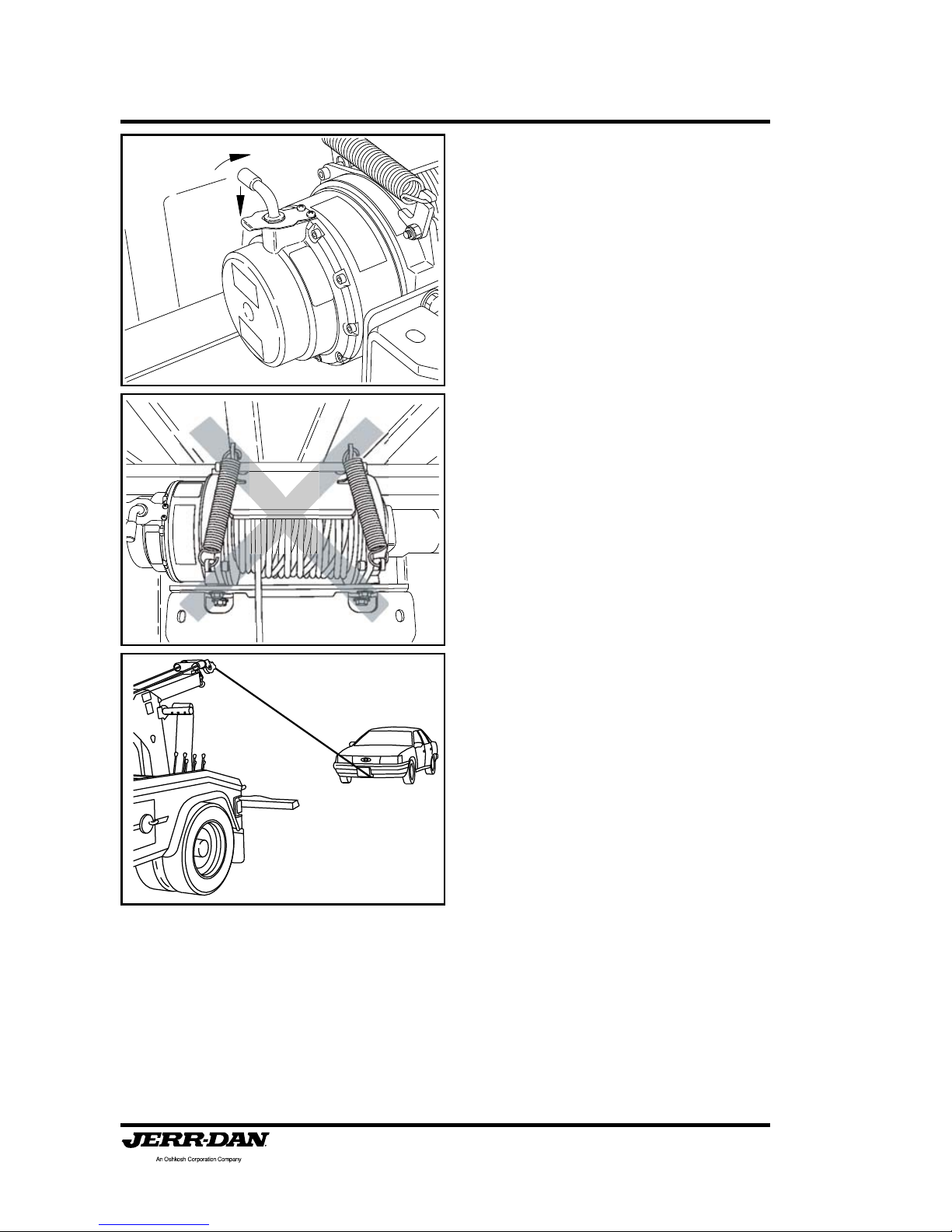
7. Set both boom winches into “free
spool” using the disengagement
levers. Raise, lift, and pull out on
the free-spool lever handle. Lower
the free-spool lever handle
capturing the lever stop bar on the
outside of the bracket locking the
winch in free-spool. Never pull
this handle while the wire
rope is under load! Moving the
boom head with the wire rope
locked can result in damage to
both the wire ropes and the boom.
Be sure both winches are free
spooling. This allows the wire
rope to be pulled directly off the
drum to the work. Unwind
enough wire rope to make the
hook-up being sure that a
minimum of at least five (5) wraps
of wire rope remains on the
drums.
8. Position the boom head by using
the boom up and down control
lever and the boom in and out
lever .

Section II: Operation
Page 45
5-376-000086
REV. 4 - 07/10
9. Attach the wire rope hook to a
chain sling, or bridle and hook
securely to the work. Be sure of
this hook up; you don’t want it
breaking loose during the pull.
(See the safety sections earlier
in this manual). Do not connect
to thin or loose body panels or
components that could break
loose during the winching
operation. Slings and bridles are
usually designed with hook
clusters on them. Most chassis
manufacturer’s provide tie-down
hooks and/or slots in chassis
frames that may be able to be
used as recovery attachment
points. (Consult the Chassis
Manufacturer’s Towing Manual
and/or the American Automobile
Association (AAA) Towing
Manuals.)
10. Re-engage the winches by
placing the free-spool levers back
to their original position. Confirm
winch engagement by jogging the
winch controls. Now slowly take
up the slack in the wire rope.
Inspect the hookup points for
slippage before continuing the lift
or pull.

Section II: Operation
Page 46
5-376-000086
REV. 4 - 07/10
11. With the wire rope tight, slowly
wind it in, observing both the work
and the drum. Be sure the wire
rope strands do not cross wrap
or criss-cross on the drum.
Observe the path the work must
travel for snags or obstructions
which could stall the movement
and overload the wire rope.
12.Once the work is in the desired
position, apply the towed vehicles
parking brake or use blocks or tie
the work down if there is any
question about stability. Slowly
reduce the wire rope tension.
After enough wire rope has been
unwound, you may remove the
hookup.

Section II: Operation
Page 47
5-376-000086
REV. 4 - 07/10
Remember, most wire rope failures are caused by cable
crushing or the operator underestimating the pull or over
estimating the wire rope strength.
13. Now slowly retrieve the wire rope,
carefully winding the wire rope
onto the drum. Many operators
take this opportunity to do a
visual inspection. When you’ve
finished rewinding the wire rope,
be sure you don’t overwind it.
Always wear safety glasses and
gloves when doing recovery work
or handling the wire rope.
Section II: Operation
Page 48
5-376-000086
REV. 4 - 07/10
TOW SLING OPERATION
(OPTIONAL)
Sling Rating: (50 M.P.H. Transport S peed)
Single Line Boom................................... 4,000 lbs.
Dual Line Boom...................................... 4,000 lbs.
If your MPL40 is equipped with a towing sling, consult the AAA
T owing Manual for hook up and follow these step s:
1. Position the truck within 9 ft.
of the subject vehicle and as
close to the direction of the tow
as possible.
2. Unfold the underlift.
9 FT

Section II: Operation
Page 49
5-376-000086
REV. 4 - 07/10
3. Remove the tow sling hold back
bar retaining pins allowing the hold
back bars to swing out of its
retaining brackets on the sides
of the boom.
4. Rotate the “CAM” handles on the
hold back bars 180° to the open
position.
5. Swing the hold back bars out
toward the lower tow sling lugs
on the back of the body. Allow
the hold back bars to extend as
necessary.
Section II: Operation
Page 50
5-376-000086
REV. 4 - 07/10
6. Connect the hold back bars to
the tow sling lugs using the pins
that you removed earlier .
7. Rotate the “CAM” handles on
the hold back bars 180° to the
close position. Raise or lower
the boom slightly until the cam
locks on the tow sling hold bars
snap into the closed position.
8. Extend the wrecker boom and
adjust the wire rope cable(s) to
lift the top of the tow sling and
tow sling straps. Extend the
boom to the yellow indicator
mark on the inner boom
section of the wrecker boom.

Section II: Operation
Page 51
5-376-000086
REV. 4 - 07/10
9. Lower the boom to allow the
tow sling head to raise out of it
holder on the back side of the
boom.
10. Carefully extend and lower the
wrecker boom to allow the tow
sling head to rotate outward and
down away from boom.
11. Lower the tow sling to the
ground.

Section II: Operation
Page 52
5-376-000086
REV. 4 - 07/10
12. Rotate the “CAM” handles on the
hold back bars 180° to the open
position.
13. Maneuver the sling under the
vehicle to be towed, far enough
under so the vehicle will ride on
the rubber belts.
14. Attach hook-up chains. The
chain J hooks must be secured
firmly around the axle or the frame
of the towed vehicle. When
fastening the J hook, be sure that
it is attached to the towed vehicle
in such a manner as to prevent
any damage to the brake lines or
other functional parts of the
vehicle.

Section II: Operation
Page 53
5-376-000086
REV. 4 - 07/10
15. With the chain securely fastened
in the hook on each side of the
bottom bar assembly, the chain
should then be wrapped around
the bottom bar. Secure the
remaining chain to the hook at the
top of the tow sling.
16. Using the tow sling with late
model vehicles, it may be
necessary to use spacer blocks
or a cross beam in order to get
sufficient height to prevent any
damage to body parts. The AAA
T owing Manual will diagram this.
17. Be sure the fuel tank is not in
contact with the sling or towing
mechanism. The fuel tank must
not support any weight
whatsoever.
18. Raise the vehicle using the
wrecker boom winches. (Read
the safety and operating
instructions for the boom and
winches beforehand.) The vehicle
should be raised until the wheels
are a minimum of ten inches off
the ground. Observe the opposite
end of the vehicle for ground
clearance.
19 . Be sure that both wire ropes are
retracted with equal tension.

Section II: Operation
Page 54
5-376-000086
REV. 4 - 07/10
20. Rotate the “CAM” handles on the
hold back bars 180° to the closed
position.
21. Retract the boom slowly drawing
the vehicle forward until the stand
offs are fully retracted and the
“CAM” handles retract to the
closed position for traveling.
22 .Install safety chains and towing
lights.

Section II: Operation
Page 55
5-376-000086
REV. 4 - 07/10
CAUTION:
The Bottom Anchor Assembly (round tube) must never be higher
than the attachment point on the rear of the truck. The Stand Off
Bar Assembly acts as a pivot in the event of a sudden stop. This
will assure that the towed vehicle will not catapult forward onto the
deck of the MPL40.
23. After the tow is complete, reverse
the procedures to unload the
vehicle.
24. With the vehicle unloaded and the
tow sling extended, use the
underlift fold function to bring the
tow sling head back up into its
storage position.
25. Rotate the “CAM” handles on the
hold back bars 180° to the open
position.

Section II: Operation
Page 56
5-376-000086
REV. 4 - 07/10
26. Remove the pins from the hold
back bars at the rear of the body .
27. Swing the hold back bars in
toward the tow sling storage
brackets on the side of the boom.
Allow the hold back bars to
retract as necessary .
28. Connect the hold back bars to
the tow sling storage brackets
using the pins that you removed
earlier.

Section II: Operation
Page 57
5-376-000086
REV. 4 - 07/10
29. Rotate the “CAM” handles on the
hold back bars 180° to the closed
position.
30.Retract the wrecker boom, snug
up the wire rope(s) and fold up
the underlift.

Section II: Operation
Page 58
5-376-000086
REV. 4 - 07/10
MOTORCYCLE TOWING ADAPTER OPERATION
(OPTIONAL)
If your MPL40 is equipped with a motorcycle towing adapter follow
these steps:
1. Lower the boom flat to the
ground.
2. Extend the wheel lift at least 6”.
3. Close the grid arms like you would
if you were loading a vehicle.
6 IN

Section II: Operation
Page 59
5-376-000086
REV. 4 - 07/10
4. Hook the loading ramp onto the
wheel grid and engage the rear
hooks on the back side of the
grid.
5. Completely retract the wheel grid
for loading.
6. Attach the lower trough and
vertical stop into the mounting
bracket at the front of the boom
with the pin and retaining pin.

Section II: Operation
Page 60
5-376-000086
REV. 4 - 07/10
7. Adjust the upper and lower tire
stops so that they will contact and
restrain the front tire when loaded.
8. Align the motorcycle with wheel
lift boom and ramp.

Section II: Operation
Page 61
5-376-000086
REV. 4 - 07/10
9. Push the motorcycle up the ramp
until the front wheel is resting in
and against the tire stops in the
front brackets.
10. Check front tire for fit with the
upper and lower tire stops. When
the motorcycle is rocked side to
side the front tire should feel solid
in the tire stops and centered in
the trough. If the front tire is not
clamped in the stops, back the
motorcycle off and readjust the
stops as necessary.
1 1. With the motorcycle stable in the
towing adapter , strap the front tire
to the wheel lift boom. Place the
hooks of the “middle” wheel
straps over the end of the boom
top plate and run the other ends
of the straps thru the front tire.
Insert the lose end of the wheel
strap into the ratchet on the end
other strap and tighten.

Section II: Operation
Page 62
5-376-000086
REV. 4 - 07/10
12. After securing the front tire,
extend the wheel lift under the
rear tire of the motorcycle raising
the rear tire of the motorcycle onto
the ramp.
13.Tie down the rear of the
motorcycle. Place the hook on
one end of the “rear” strap into
the hole on the front side of the
grid. Place the other hook onto
the motorcycle and tighten.
Repeat for the other side.
14. Raise the underlift boom to the
desired towing height.
CAUTION:
Care should be taken when lifting
the boom. Do not try to level the
underlift. The straps may
overtighten or become loose.

Section II: Operation
Page 63
5-376-000086
REV. 4 - 07/10
15.Tie the front of the motorcycle to
the rear of the wrecker body.
Attach the lasso style straps to
each of the handle bars.
16. Place the hook on one end of the
“front” strap to the loop of the
lasso strap on the handle bars
and place the hook on the other
end to the rear of the wrecker
body and tighten with the ratchet.
Repeat for the other side.
17. Use the wheel lift safety chains
to prevent the wheel grid from
pivoting during travel. Loop the
end of the safety chain around the
grid and secure with the grab
hook. Remove the slack in the
chain and secure the chain in the
keyslot of the chain box.

Section II: Operation
Page 64
5-376-000086
REV. 4 - 07/10
18 . Attach towing lights.
19. Reverse the loading procedures
to unload the motorcycle.

Section II: Operation
Page 65
5-376-000086
REV. 4 - 07/10
DOLLY STORAGE OPERATION
(OPTIONAL)
If your MPL40 is equipped with a towing dolly , follow these steps for
dolly removal and storage:
1. Remove the retaining bolts and
wing nuts or pad locks, which
ever your unit may have.
2. Open dolly the retaining latch by
pulling the top toward you.

Section II: Operation
Page 66
5-376-000086
REV. 4 - 07/10
3. After you have the latch open, the
dolly is free to be removed.
4. Remove the dolly wheel
assemblies, the axle cross tube
rails and the pry bar/jack bar .
5. Load dollies. (See Dolly
Operation instructions).
6. Afterloading the dollies, place the
pry bar/jack bar back into the
storage bracket by inserting the
end of the bar with the ring around
it thru the cutout in the front
bracket. Allow the other end of
the bar to rest on the rear bracket.

Section II: Operation
Page 67
5-376-000086
REV. 4 - 07/10
7. Close the dolly latch by pushing
the top away from you.
8. Install the retaining bolts and
wing nuts or pad locks.
9. After using the dollies, store them
back on the deck in basically the
reverse order. Remove the
retaining bolts and wing nuts or
pad locks and open the latch.
10. Place the axle cross tube rails
back into the storage bracket by
inserting the tab on the end of the
axle tube into the cutout in the
storage bracket.

Section II: Operation
Page 68
5-376-000086
REV. 4 - 07/10
1 1. The axle cross tube rails need to
be stored with the wheel ramp
plates turned in and up.
12.Allow the axle cross tube rails to
hang from the bracket by the tab.
13. Place the dolly wheel assemblies
back into the storage brackets.

Section II: Operation
Page 69
5-376-000086
REV. 4 - 07/10
14. The tab on the storage bracket
should be placed through the dolly
pocket of the dolly wheel
assembly.
15. Close the dolly retaining latch by
pushing the top away from you.
16. Install the retaining bolts and
wing nuts or pad locks.

Section II: Operation
Page 70
5-376-000086
REV. 4 - 07/10
DOLLY OPERATION
(OPTIONAL)
Specifications:
Dolly Capacity: ................................................ 2,360 lbs.
Tire/Wheel: ............................................4.80 x 4.00/8Tire
Axle: .................................................... 2 1/2 Sq. Tube
Max. Speed: .................................................... 50 M.P.H.
The Quick Loading Dolly is simple to use once the principles of the unit are
understood.
1. Extend telescopic cross rails by first depressing spring-loaded
plunger and sliding inner (male) tube until plunger locks into the
hole that matches the width of vehicle to be towed.
2. Place cross rails on ground, fore and aft of vehicle’s tires.
3. Place dolly in the fully collapsed position with the dolly tires closest
to each other .
4. Set rail ends into dolly pockets, adjusting for the size of vehicle’s
tires, positioning rails as close as possible to tires.
5. Make sure safety locks are disengaged, allowing trip assemblies
freedom of movement while lifting vehicle.
6. Engage ratchet assemblies to prevent injury and damage to the
operator and vehicle in case pry bar slips from hand.
7. Insert pry bar into pry bar pocket.
8. Swing outer end of pry bar in an arc until trip assembly rises then
locks spindle assembly in the down position. Do not release pry
bar until spindle assembly is locked down.
9. Repeat this action for all four (4) assemblies. Dolly is now raised.
10 . After dolly is in the raised position, engage safety locks over trip
assemblies to prevent releasing while vehicle is in tow .

Section II: Operation
Page 71
5-376-000086
REV. 4 - 07/10
11. Safety tie-down straps should be used to secure dolly to vehicle in
case of rough road. Dolly is now ready for towing.
BE SURE EACH WHEEL IS SECURELY HELD IN ITS DOLLY AND
INSPECT THE GROUND CLEARANCE OF THE VEHICLE BEFORE
A TTEMPTING A TOW.
T o unload the vehicle, stand clear of both the vehicle and the dollies and slip
the chain link off of the cam bar. Carefully slide the jack handle over the
cam bar and slowly lift the handle allowing the vehicle to drop. Repeat this
step on the other dolly and then remove the axles from the dollies.
USE CARE WHEN RELEASING OR UNLOCKING THE CAM BAR AS IT
CAN MOVE SUDDENL Y AND WITH FORCE, CAUSING INJURY. JERRDAN ASSUMES NO LIABILITY FOR THE USE OR MISUSE OF THESE
DOLLIES OR ANY DAMAGE CAUSED BY THEM.

Section II: Operation
Page 72
5-376-000086
REV. 4 - 07/10
THIS P AGE INTENTIONALL Y LEFT BLANK

Section III: Maintenance
Page 73
5-376-000086
REV. 4 - 07/10
MAINTENANCE AND LUBRICATION
Y our MPL40 has been designed to give you excellent service and long life
but like all equipment, it requires proper and periodic maintenance. The
truck chassis itself is on a maintenance schedule recommended by the
manufacturer . Follow these guidelines and protect your vehicle warranty.
There are a number of different lubricants used on your MPL40 and the
following chart details the proper lubricant and the most common brands
and specification which meet the requirements.
Use only safe practices when maintaining this equipment. Always shut off
the engine before reaching into pinch areas.
Inspect the vehicle and underlift system periodically for damage or evidence
of pending failure. Damaged or broken parts should be replaced immediately .
Never operate a machine which is known to be defective or operating
improperly. The cause of any binding or leakage should be determined
immediately and the problem promptly fixed.
Y our MPL40 has Jerr-Dans “No-Lube” maintenance-free pivot joint system.
Most of the pivot joints utilize high strength composite bearings with
hardened and plated pins to drastically reduce maintenance, down-time
and the cost of lubrication over the life of the product. There are however a
few areas that still require some lubrication or maintenance. Sliding surfaces
should be cleaned periodiacally. The following chart and diagram shows
the location of these points, and when and what type of lubricant to use.
Check the hydraulic oil level bi-monthly or after any leakage. The proper oil
level is best checked with all cylinders fully retracted. The hydraulic oil
should just cover the bottom of the screen in the oil filler neck of the hydraulic
tank. Use a Super Premium Grade Multi-Viscosity hydraulic oil. (See Chart)
(Automatic transmission fluid may be used in the hydraulic system if
necessary.)
The hydraulic filter located on the return side of the hydraulic tank comes
equipped with a restriction indicator gauge. This gauge shows the operator
the condition of the filter element. When the needle reaches the red band
(25 psi), the filter is starting to bypass and the element needs to be changed.
Failure to change the element will result in premature wear and/or failure of
any or all of the hydraulic components. Check gauges when the hydraulic
MAINTENANCE

Section III: Maintenance
Page 74
5-376-000086
REV. 4 - 07/10
fluid is at operating temperatures. Cold oil is more dense and will
give a false indicator gauge reading.
If a cylinder seal leaks, disassemble the cylinder and ascertain the cause
of the leak. Small scores caused by chips or contaminated fluid can usually
be worked out with fine emery cloth to avoid repetition of the trouble. Whenever
any seal replacement is necessary, it is always advisable to replace all
seals in that component. These seals are available in kits. Also, thoroughly
clean all components before reassembly .
The body of your Jerr-Dan has been built from high strength aluminum which
has been carefully assembled and polished in our factory . To keep it clean
and free of dirt use any non-abrasive soap or detergent recommended for
automotive finishes. Use a soft cloth or sponge and finish with a thorough
rinsing. Drying with a soft cloth or chamois will prevent spotting or streaking.
A coat of automotive wax is recommended.
The MPL40 is mounted to the truck chassis by bolts. These bolts are
torqued at the factory to 70 ft. lbs. The MPL40 aluminum body is mounted
to the subframe by bolts. These bolts are torqued at the factory to 70 ft.
lbs. We recommend periodic inspection and retorquing of these bolts. Your
truck is equipped with winches and the winch mounting bolts should be
regularly inspected and tightened if necessary. Replace any broken or
damaged bolts immediately .
Section III: Maintenance
Page 75
5-376-000086
REV. 4 - 07/10
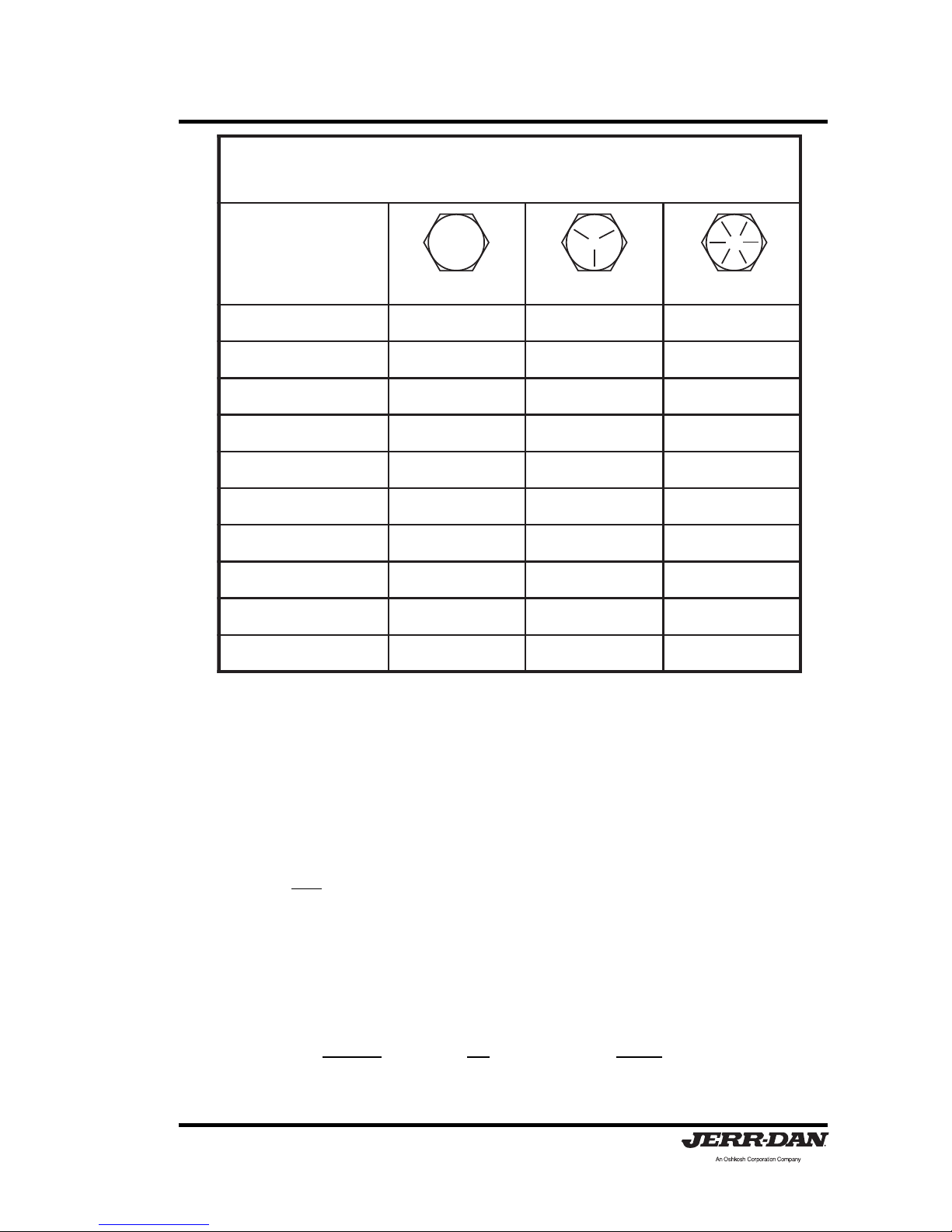
· All torque values shown are for bolts (cap screws) and nuts that are either zincplated or lubricated.
· Torques shown above apply to screws and nuts used for assembly and
installation of all wrecker components.
· Different torque values may be given in instructions for certain components due to
short thread engagement or low-strength internal threads.
· When nuts are used, tighten nuts to torques shown (screws or bolts should be
held but not turned).
· Retighten nuts of all mounting screws that secure the wrecker and wrecker-body
within two weeks after they are first installed on the vehicle. Thereafter, inspect
such screws and nuts visually once every month and after each job imposing
extremely heavy loads on the equipment. Periodically recheck all accessible
screws and nuts for proper tightness.
· Converting ft/lbs to Nm (Newton metres) can be accomplished by using the
following:
Multiply: by: to get:
ft/lbs x 1.3558 = Nm (Newton metres)
)SDNUOP-TOOF(SEUQROTGNINETHGIT
STUNDNASWERCSROF
EZIS
)MM(SEHCNI
2EDARG5EDARG8EDARG
)053.6(4/16801
)839.7(61/5014191
)525.9(8/3717233
)211.11(61/7825406
)007.21(2/1548609
)882
.41(61/936001021
)578.51(8/509531081
)050.91(4/3541032013
)522.22(8/7541083005
)004.52(102207506
7

Section III: Maintenance
Page 76
5-376-000086
REV. 4 - 07/10
OILS AND GREASES
The following oils and greases are suitable for use with your Jerr-Dan.
Company Product
HYDRAULIC OILS
1. Chevron A W Hydraulic Oil MV
2. Exxon Univis N32
3. Mobil DTE13
4. Texaco Rando DHZ-32
5. Shell T ellus Oil T 32
6. Citgo A/W All T emp
7. Amoco Rycon Oil 32
8. Conoco AW Hydraulic Fluid MV 46
9. Mobil DTE11M
(for cold weather use)
10. Conoco A W Hydraulic Fluid MV 32
(for cold weather use)
GREASES
1. Drydene HD Lithium EP2
2. Gulf Crown EP2
3. Amoco Amolith EP2
4. Shell Alvania EP2
5. Texaco Marfax EP2
6. Mobil Mobilux EP2
7. Sunoco Prestige EP2
WINCH AND GEAR LUBE
1. Phillips 140 wt. EP Gear Lube 93301
(or approved equivalent)
2. Mobil Mobil SCH624
(or approved equivalent for
cold weather use)

Section III: Maintenance
Page 77
5-376-000086
REV. 4 - 07/10
WIRE ROPE HANDLING AND INSPECTION
Wire Rope WILL FAIL if worn-out, overloaded, misused, damaged,
improperly maintained or abused.
Wire rope failure may cause serious injury or death!
Protect yourself and others:
• ALWAYS INSPECT wire rope for WEAR, DAMAGE or
ABUSE BEFORE USE.
• NEVER USE wire rope that is WORN-OUT, DAMAGED or
ABUSED.
• NEVER OVERLOAD a wire rope.
• INFORM YOURSELF: Read and understand
manufacturer's literature or "Wire Rope and Sling Safety
Bulletin".
• REFER TO APPLICABLE CODES, STANDARDS and
REGULATIONS for INSPECTION REQUIREMENTS and
REMOVAL CRITERIA.
WARNING
A new wire rope requires a break in period. Run the wire rope through
several cycles at low speeds gradually increasing the load on the wire rope.
Make sure that the wraps of the wire rope are tight and evenly wound on the
winch drum. A loose wire rope on the winch drum will cause crushing of the
wire rope when heavy loads are applied.
All wire rope in continuous service should be observed during normal operation
and visually inspected on a weekly basis. A complete and thorough
inspection of all ropes in use must be made at least once a month and all
rope which has been idle for a period of a month or more should be given a
thorough inspection before it is put back into service. All inspections should
be the responsibility of and performed by an appointed competent person
with the training and experience to look for deterioration of the wire rope.

Section III: Maintenance
Page 78
5-376-000086
REV. 4 - 07/10
It is good practice , where the equipment is consistently in use, to give the
rope a certain length of service, several hundred hours, several weeks or
months and then renew the rope regardless of it's condition. This method
eliminates the risk of fatigue causing rope failure.
Any deterioration, resulting in a suspected loss of original rope strength,
should be carefully examined and a determination made as to whether further
use of the wire rope would constitute a safety hazard.
There are certain points along any given rope which should be given more
attention than others, since some areas will be subjected to greater stresses,
forces, and hazards. Some of these areas include at the winch drum, at the
boom sheaves and at the end attachments.
All products are subject to age, wear and deterioration, all of which cause a
reduction in the products breaking strength capacity.
Probably the most common sign of rope deterioration and approaching failure
is broken wires. Inspection criteria are specific as to the number of broken
wires allowable under various circumstances. It is important that a diligent
search be made for broken wires, particularly in critical areas. Inspection of
wire rope ends should include hooks and thimbles.
Any wire ropes that have been abraded, crushed, kinked or twisted should
be replaced.
Wire rope should be routinely cleaned of any and all debris. Grit and gravel
can quickly reduce a wire ropes life. A wire rope should be well lubricated
so that it can act and perform as it was designed. Lubrication keeps a wire
rope flexible and free from rust.
Consult the manufacturer or your local distributor for the proper replacement
wire rope.

Section III: Maintenance
Page 79
5-376-000086
REV. 4 - 07/10
KNEE BOOM REF
MOVE SENSOR UPWARD TO
LOWER UNDERLIFT GRID;
DOWNWARD TO RAISE
UNDERLIFT GRID
NOTE:
A GAP OF .125-.1875 MUST BE MAINTAINED
BETWEEN THE SENSOR AND THE BASE BOOM
SIDE PLATE. INTERMITTENT OPERATION WILL
OCCUR IF THE GAP IS NOT MAINTAINED.
To change or adjust the factory set positions of the Underlift Level Stop
Assist system, follow these steps:
MPL40
1. To change the tilt stop, move the sensor on the underlift boom base
up, to lower the boom, and down to raise the boom as shown below .
2. To change the boom stop, move the sensor on the boom lift cylinder
up, to raise the boom, and down to lower the boom as shown below .
BOOM LIFT CYLINDER REF
MOVE SENSOR UPWARD TO
RAISE UNDERLIFT; DOWN-
WARD TO LOWER UNDERLIFT
NOTE:
A GAP OF .125-.1875 MUST BE MAINTAINED
BETWEEN THE SENSOR AND THE DOUBLER PLATE.
INTERMITTENT OPERATION WILL OCCUR IF THE
GAP IS NOT MAINTAINED.

Section III: Maintenance
Page 80
5-376-000086
REV. 4 - 07/10
LUBRICATION POINTS
The following lubrication chart is located inside the tool box lid on the driver’s
side of the MPL40 body .

Section III: Maintenance
Page 81
5-376-000086
REV. 4 - 07/10
TROUBLE SHOOTING
Y ou probably won’t require anything but preventive maintenance to keep
your MPL40 running, however , the following chart should help you isolate
and correct minor problems if they occur with use. Any service work on
the hydraulic system should be performed by qualified mechanics.
HYDRAULIC SYSTEM
Problem Cause Solution
Slow operation a. Low engine RPM a. Speed up engine
b. Low oil level b. Check dipstick and fill with
the specified oil
c. Blocked or restricted c. Inspect: remove blockage
hoses
d. Dirty hydraulic oil d. Drain, flush and refill with
clean oil, replace filter
e. Hydraulic pump worn e. Rebuild or replace
f. Clutch Pump belt slipping f. Tighten or Replace belt
Valve Solenoid(s) a. Broken centering spring a. Inspect, clean or replace
sticking or frozen or clogged with foreign
material
b. Low Amperage/Voltage b. Check Amperage/Voltage
at Solenoid
Valve leaks a. Defective seals a. Replace
Cylinder leaks a. Defective seals or rods a. Inspect and replace
b. Dirty or Defective b. Clean or Replace
CounterBalance Valve CounterBalance Valve
Erratic cylinder a. Air in the system a. Cycle hydraulic system 10
function to 15 times to remove air
b. Defective pump b. Replace if necessary
(pulsating)
Remote hand a. Electric power turned off a. Turn on CONTROL power
controller fails to switch in cab
respond b. Not plugged in b. Check plug connection
c. Faulty Remote Hand c. Use Manual Controls
Controller at Rear of Body

Section III: Maintenance
Page 82
5-376-000086
REV. 4 - 07/10
HYDRAULIC CLUTCH PUMP
Problem Cause Solution
No oil flow from a. No oil in reservoir a. Fill hydraulic reservoir
pump b. Pump not “primed” b. Fill inlet hose from pump
end
c. Clutch not engaging c. Check wiring/fuse
Pump will not build a. Relief valve improperly set a. Adjust relief valve to manuor hold pressure facturers specification
b. Relief valve stuck open b. Remove, clean and reset
Pump is noisy - a. Air in the system a. See “Oil Foaming”
whines b.Cavitation b. Check Hoses, Reservoir
breather or strainer
Pump is noisy - a. Belts are worn/loose a. Inspect, adjust and/or
squeals replace
b. System horsepower b. Review application
demand exceeds belt
capacity
c. Clutch is slipping c. Check voltage/ground
Pump ‘throws” belts a. Engine and pump pulley a. Check installation
alignment
b. System horsepower b. Review application
demand exceeds belt
capacity
c. High-speed engagement c. Reduce start-up RPM
Pump leaks at shaft a. Damaged seal a. Replace seal
seal b. Damaged pump body b. Replace pump body
Pump leaks at body a. Damaged seal a. Replace seal
section b. Damaged pump body b. Replace pump body
c. Body section bolt torque c. Torque to specification
Pump leaks a a. Loose fitting a. Inspect and/or tighten
fittings b. Damaged fitting b. Replace fitting
c. Damaged pump body c. Replace pump body
Pump is overheating a. Low oil level a. Fill hydraulic reservoir
b. Dirty oil b. Replace oil and filter
c. Relief valve stuck open c . Remove, clean and reset
d. Relief valve improperly set d. Adjust relief valve to manu-
facturers specification
e. Improper weight oil e. Replace with correct oil
Oil foaming a. Low oil lever a. Fill hydraulic reservior
b. Improper oil b. Fill with correct oil

Section III: Maintenance
Page 83
5-376-000086
REV. 4 - 07/10
P.T .O. FUNCTIONING IMPROPERLY
Problem Cause Solution
Cable tight or frozen a. Cable kinked or bent a. Straighten or replace
b. Cable and P.T.O. connec- b. Inspect and adjust
tion not adjusted properly
c. Mounting bracket nuts c. Loosen if necessary
are over tightened at P.T.O.
Rattling noise in a. P.T.O. backlash too loose a. Shims must be removed
P.T .O . (Consult P.T .O. Manual)
Howling Noise in a. P.T.O. backlash too tight a. Shims must be added
P.T .O . (Consult P.T .O. Manual)
Gear oil leak between a. Defective shaft seal a. Remove and replace
P.T.O. and pump
P.T.O. will not engage a. Cable and P.T.O. connec- a. Inspect and adjust
or disengage tion not adjusted properly
b. Defective shifter cover b. Inspect and replace
plate
HYDRAULIC PUMP
Problem Cause Solution
Pump noisy a. Low oil supply a. Fill to proper level
(Cavitation) b. Heavy oil b. Fill with proper oil
(See chart)
c. Dirty oil filter c. Replace filter
d. Restriction in suction line d. Clean out and remove
e. Pump worn e. Repair or replace
Pump/Clutch Pump a. Low oil supply a. Fill to proper level
slow or fails to b. Worn or Loose Belt(s) b. Tighten or Replace Belt(s)
respond
Oil heating up a. Foreign material lodged in a. Inspect and remove/
relief valve replace filter
b. Using too light oil b. Drain and refill with clean
oil
c. Dirty oil c . Drain, flush and refill with
clean oil/replace filter
d. Oil level too low d. Fill to proper level
e. Pump worn (slippage) e. Repair or replace

Section III: Maintenance
Page 84
5-376-000086
REV. 4 - 07/10
HYDRAULIC PUMP - con’t
Problem Cause Solution
Oil foaming a. Air leaking into suction line a. Tighten all connections
b. Wrong kind of oil b. Drain and refill with
non-foaming type of
hydraulic oil (See
lube chart)
Replace filter
c. Oil level too low c. Refill to proper level
Hydraulic oil leak a. Defective shaft seal a. Replace shaft seal
between P.T.O. and
pump
Clutch Pump leaks at a. Defective Shaft Seals a. Replace seals or Pump
Pulley Shaft b. Hydraulic Supply/Return b. Check hydraulic line
lines connected incorrectly connections
Pump leaks at front a. Defective seals a. Replace seals
and rear covers
WINCH FUNCTIONING IMPROPERLY
Problem Cause Solution
Winch screeches a. Insufficient lubrication a. Lubricate per lube chart
during operation
Winch will not pull a. Free spooling device not a. Engage
load or take in cable engaged
b. Sheared keys or broken b. Inspect or replace
coupling
c. Hydraulic pump worn c. Inspect and replace
d. Insufficient pump d. Check hydraulic pump
pressure and hydraulic fluid level
e. Overload e. Install snatch block in the
rigging line

5-376-000086
REV. 4 - 07/10
Section IV: Glossary
Page 85
A
Anchoring Device - Used to attach cable ends, snatch blocks, safety chains,
and tie-down assemblies to the towing vehicle.
Approach Angle - Angle between the plane of the platform and the ground.
Attachment - Any device that can be added to a basic unit or assembly.
Auxiliary Braking Device - A device which attaches to the disabled vehicle to
assist the tow truck's brakes in retarding or stopping both vehicles.
Auxiliary Equipment - Equipment that is not necessary to perform the basic
function of the primary equipment.
Auxiliary T owing Lights - S top, tail, and turn signal light s att ached to the trailing
end of the towed vehicle and operated as part of the towing vehicle lighting
system.
B
Bending Moment - The force times the distance from a reference point to the
point the force is applied causing bending.
Bird Nesting - The tangling and intertwining of wraps and layers on a drum.
Body - The structure mounted on a chassis cab or that portion of the vehicle that
carries the load.
Body Hinge - The attachment mechanism connecting the body to the hinge pin
at the pivot axis about which the body rotates into the tilt position.
Body Subframe - Another term for body understructure or mounting frame.
Body Weight - Unmounted weight of a body with applicable options.
Boom - The structure member that supports the load.
Boom Angle - The boom angle is measured between a horizontal line and a line
through the boom pivot and center of sheave.
Boom Head - The structural member at one end of the boom which can swivel
and support the load lifted through the sheave and sheave support device.
GLOSSARY OF TERMS

5-376-000086
REV. 4 - 07/10
Section IV: Glossary
Page 86
Boom Length - The straight line distance from center of the revolving base to the
center of the boom head.
Brakes - Parking - A system used to hold a stopped machine in a stationary
position.
Brakes - Service - A primary brake system used for retarding and stopping the
truck.
Bumper - DOT - A bumper designed to provide rear-end protection that meets
the requirements of FMCSR 393.86.
Bus Bar Grid - A device used for towing vehicles by lifting one end of the towed
vehicle by the wheels.
C
CA (Cab to Axle) - The distance from the back of the truck cab to the center of the
rear axle.
CG (Center of Gravity) - The point at which the weight of the chassis, body/
equipment and payload, if collectively or individually supported, would
balance vertically, horizontally, and laterally.
CT (Cab to Tandem) - The distance from the back of the truck cab to a point
midway between the tandem axles.
Cable - Steel wire rope used for pulling.
Car Carrier - Vehicles equipped to transport other vehicles mounted on a flat
platform and/or with an additional assembly attached to the rear to facilitate
towing a second vehicle. These units are also known as slidebacks,
rollbacks, transporting equipment carriers and flatbeds. See Carrier.
Carrier - A platform body with a winch for loading.
Casualty Vehicle - The damaged or disabled vehicle.
Capacity - The load that a machine can lift at any given point.
CAUTION - A signal word used when a potentially hazardous situation exists that
might result in minor injury or property damage.

5-376-000086
REV. 4 - 07/10
Section IV: Glossary
Page 87
Certification Label - Required by Public Law 89-563, which states that a motor
vehicle or item of motor vehicle equipment complies with all applicable
Federal Motor Vehicle Safety Standards (FMVSS) in effect on the date of
manufacture.
Chain Assemblies - Chain with all hardware and coupling devices.
Chassis Cab - A vehicle consisting of a chassis upon which is mounted a cab;
capable of being driven by the addition of wheel or other items of running
gear, but lacking a body or load-carrying structure.
Completed Vehicle - A vehicle that requires no further manufacturing operations
to perform its intended function, other than minor finishing operations such
as painting.
Component - Any p art of an assembly on a machine when referred to individually .
Control - A device used to control the functions of a unit.
Control Lever- A device for imparting motion into a control linkage.
Crossbar - A transverse horizontally pivoting member attached to the boom of a
wheel-lift or underlift for attaching towing accessories.
Curb Side - The right or passenger side of the vehicle when viewed from the
rear, opposite side from ROADSIDE.
Curb Weight - The weight of a vehicle in operational status, with all standard
and commonly installed equipment and the fuel tank(s) filled to capacity.
Cylinder - A device which converts fluid power into a linear mechanical force and
motion usually consisting of a movable piston and piston rod within a cylinder
bore.
D
DANGER - A signal word used when an imminently hazardous situation exists
that can result in death or serious injury.
Disabled Vehicle - Any vehicle that cannot operate under its own power.
Dolly - A four-wheeled carriage used in towing to support the trailing end of the
towed vehicle.

5-376-000086
REV. 4 - 07/10
Section IV: Glossary
Page 88
DOT (Department of T ransportation) - A federal agency dealing with regulations
concerning both the manufacture and operation of motor vehicles and motor
vehicle equipment. See NHTSA.
Driveline - The driveshaft and associated joints.
Drum - Any spool on which are wrapped ropes used in machine operation.
E
Extend Cylinder - Cylinders used to extend or retract boom structures.
F
Filter- A device whose primary function is the retention by a porous media of
insoluble contaminants from a fluid.
Final Stage Manufacturer - A person, firm, or corporation who performs such
manufacturing operations on an incomplete vehicle that it becomes a
completed (end-user) vehicle.
FMVSS (Federal Motor Vehicle Safety Standards) - Regulations promulgated
by NHTSA under Public Law 89-563, which are mandatory and must be
complied with when motor vehicles or items of motor vehicle equipment are
manufactured and certified thereto.
Frame - Structure on which either the upper or lower equipment is located.
Frame Cutoff - Centerline of rear axle(s) to the rearmost point of the chassis
frame as modified for body installation.
Frame Lift - See Underlift.
Frame Section Modulus - The engineering term that indicates the relative
strength of frames as it relates to shape. It takes into account frame depth,
flange width, and material thickness. All other things being equal, the frame
with the largest section modulus will have the greatest strength and stiffness,
i.e., the ability to more effectively resist deflection under load.
Free Spool - The operation of unspooling wire rope from a drum by pulling on
the end of the wire rope while the winch is stationary. The drum is
disconnected (declutched) from its powertrain during this operation.

5-376-000086
REV. 4 - 07/10
Section IV: Glossary
Page 89
Forks - A device attached to the lift bar for lifting a vehicle by the tires, axle, frame,
or structural member. May be classified as chain, axle, or frame forks.
FW (Frame Width) - The overall width of the chassis frame measured outside to
outside behind the cab.
G
GAWR (Gross Axle Weight Rating) - The value specified by the manufacturer as
the load-carrying capacity of a single-axle system as measured at the
tire-roadway interface.
GCWR (Gross Combination Weight Rating) - Represents the entire weight of a
vehicle on the ground with a trailer or trailers including vehicle, equipment,
driver, fuel, and payload (everything that moves with the vehicle.) Gross
combination weights published represent maximum allowed.
Grab Hook - For use with chains and some tow-sling hookups.
Grid - A device that att aches to the lift bar for engaging the tires of a towed vehicle.
GVWR (Gross V ehicle Weight Rating) - The maximum total vehicle rated capacity ,
measured at the tire ground interface, as rated by the chassis manufacturer .
GVW (Gross Vehicle Weight) - Value specified by the manufacturer as the
maximum loaded weight of a single vehicle including all equipment, fuel,
body , payload, driver , etc.
H
Headboard - Structure on which an emergency light bar is mounted.
Hook-up Chains - Length of chain used to connect a recovery vehicle to a casualty
vehicle.
Horizontal Center of Gravity (HCG) - The point at which half of the gross weight
is forward and half is aft.
Hydraulic Control V alve - A mechanical device to divert or control the flow of fluid
in a hydraulic system.
Hydraulic Hose - Flexible oil lines used to transmit fluid.

5-376-000086
REV. 4 - 07/10
Section IV: Glossary
Page 90
Hydraulic Oil - Fluid used in operation of hydraulic systems.
Hydraulic Relief Valve - A mechanical device used to limit the pressure in a
hydraulic circuit.
I
Incomplete Vehicle - As assemblage consisting, as a minimum, of a frame and
chassis structure, powertrain, steering system, suspension system and
braking system to the extent that those systems are to be part of the complete
vehicle that requires further manufacturing operations.
Independent - The Wrecker Boom and Underlift Boom are separate
(independent) from each other.
Integrated - The Wrecker Boom and Underlift Boom are combined together as
a complete unit.
J
J-Hook - Attachment device used for towing/recovery.
L
L-Arm - See Wheel Arm
Layer - All wraps of the same diameter on a drum.
Lift Bar - A traverse horizontally pivoting member attached to the boom of a
wheel-lift or underlift for attaching towing accessories.
Lift Cylinder - Cylinders used to raise or lower boom structures.
Lift Forks - See Forks.
Lifting Capacity - The load that a machine can lift at any given point.
Lift Tow Rating - Maximum Steering Towing Load.
Light Bar (Emergency) - An array of lamps used in accordance with local
ordinances.

5-376-000086
REV. 4 - 07/10
Section IV: Glossary
Page 91
Light Pylon - Structure on which an emergency light bar is mounted.
Line Pull - The maximum wire rope pull, in pounds, at the drum, at full-load
engine speed, with specified lagging diameter.
Line Speed - S peed in feet per minute of a single rope, based on full load engine
speed with specified lagging diameter.
M
Marker Lights - Small amber and red lights attached to bodies to indicate
overall clearance at night.
Maximum Loaded Vehicle Weight - The sum of curb weight, passengers and
cargo.
Motor - A rotary motion device which changes hydraulic energy into mechanical
energy.
Motor V ehicle Safety St andards - See FMVSS.
Mud Flap - Splash-Deflecting shields at rear of wheel.
N
NHTSA (National Highway T raffic Safety Administration) - The federal agency
responsible for promulgating and insuring compliance of regulations dealing
with the manufacture and certification of motor vehicles or items of motor
vehicle equipment. See DOT.
O
Outriggers - A beam type device attached to frame of a truck or rubber tired
carrier , to provide maximum stability by reducing load on tires and increasing
width of operating base.
Overall Vehicle Height - Distance from the ground to the highest point on the
vehicle with equipment in stowed position.

5-376-000086
REV. 4 - 07/10
Section IV: Glossary
Page 92
Overall Vehicle Width - The design dimension ot the widest part of the vehicle,
exclusive of signal lamps, outside rearview mirrors, flexible fender
extensions, and mud flaps, determined with doors and windows closed
and the wheel in the straight ahead position.
Overhang - The horizontal distance for the centerline of a single rear axle or
center point of a tandem rear axle to a point where the vertical component is
imposed.
P
Payload - The weight of the commodity being hauled. Payload capacity is
computed by subtracting the completed weight of the vehicle (including
driver and passengers) from the GVWR.
Pintle Hook - Hook mounted on a truck or semitrailer used to couple a full trailer .
PTO (Power Takeoff) - Mechanical device used to transmit engine power to
auxiliary equipment. Power takeoffs can be mounted on either a main or
auxiliary transmission. Front mounted and flywheel mounted power takeoffs
are also used in various applications.
Push Bumper - Device used to push a vehicle, sometimes equipped with a
rubber face.
R
Rating - The specified design operating limit of a device.
Rear Jack - One or more devices designed, when used, to stabilize chassis.
Recovery - Act of moving a vehicle to a position from which it can be driven or
towed.
Recovery V ehicle - Vehicle to retrieve and if necessary lif t and tow other vehicles.
Resisting Bending Moment (RBM) - A calculation used to compare frames of
different section modulus and of different material. It is the product of the
section modulus times the yield strength of the frame material.
 Loading...