

Jeppesen Marine Workboat Navigator 1.3 User Manual
Jeppesen
Workboat Navigator
A Professional Information Service
User's Guide v. 1.3

ii
Jeppesen Workboat Navigator User’s Guide

Welcome
Welcome
Thank you for purchasing Jeppesen Workboat Navigator for inland waterways.
This Installer’s Guide is written for an audience assumed to be familiar with marine
navigation and computer operation and usage. This document should in no way be
used to replace real navigation training and experience.
iii
Welcome
WARNING
by people who have training and experience in such navigation. Jeppesen
Workboat Navigator is intended for use only as an aid to navigation.
©2006-2007 Jeppesen Marine. All rights reserved.
To Contact Jeppesen Marine
Jeppesen Marine, Inc.
55 Inverness Drive East
Englewood, CO 80112-5498 USA
Customer Support Phone Numbers:
USA: 1 866 845 8605 8 AM - 5 PM PST
International: 49 61 02 5070
Do You Have Everything?
Before installing the software, make sure
you have received the following:
Jeppesen Workboat Navigator
•
Software Disc
Jeppesen NavData® Disc(s)
•
Product Security Key (USB Port device)
•
Jeppesen Workboat Navigator User’s
•
Guide (this book)
Available Hardware Interfaces
GPS or other device that transmits
•
boat position - required
AIS Transceiver - optional
•
Heading Sensor - optional
•
Depth Sensor - optional
•
Wind Sensor/Anemometer - optional
•
Nobeltec® InSight Radar 2 - Black
•
Box (IR2-BB)™ - optional
Radar system with ARPA/MARPA
•
output
NOTE:
Marine does not provide a
hardware installation document.
Hardware devices need to be
connected to your computer
by a certified marine electronic
technician. Verify if your onboard
hardware is compatible with
Jeppesen Workboat Navigator
prior to setup.
: Marine navigation can be dangerous, and should be performed only
System Requirements
Minimum system requirements:
2.0 GHz (or faster) Pentium 4
•
Processor or 1.6 GHz (or faster)
Mobile Processor
512 MB RAM
•
80 GB HD space (minimum 20 GB) *
•
SuperVGA (SVGA) card capable of
•
1024x768 resolution or higher ±
•
Serial ports must match number of
•
input devices or use a multiplexer
1 USB 2.0 port (available)
•
DVD drive or CD/DVD combo drive
•
Sound/speaker connections
•
Mouse, trackball, or pointing device
•
Keyboard
•
Windows XP Professional, SP2
•
Monitor supporting 1024x768 or higher
•
Recommended system requirements:
1 GB RAM
•
Flat panel monitor - daylight readable,
•
multiple mounting options (prefer
multiple sizes available: 12”, 15” and
17”) - 1024x768 resolution or higher
10/100 Ethernet
•
Enclosure with fixed mounting options
•
Shock mounting preferred (environment
•
At this time, Jeppesen
subject to extreme vibration)
Optional video input support ‡
•
IEC 60945 preferred
•
Installation should not be started
*
unless available disk space has
been verified
DO NOT SET RESOLUTION TO 864x1152,
±
as this setting may cause distortion.
For video camera support
‡
Display Settings - 32 bit quality


Chapter Name
Table of Contents
v
Table of Contents
1 - Introduction 1
Jeppesen Workboat Navigator 1
Screen Layout 1
Professional+ Charts and NavData® 2
Hardware Overview 2
GPS (required) 2
AIS/Target Tracking 2
Heading Sensor 2
Depth Sensor 2
Sounder 2
Autopilot 2
Wind Sensor/Anemometer 3
Radar and the IR2-BB 3
Limits of Electronic Navigation 3
2 - Workboat Navigator Look and Feel 5
Glossary for this Chapter 5
Workboat Navigator Window Panes 5
Default View 5
Chart Window Pane 7
NavInfo Window Pane 7
SysInfo Window Pane 8
Radar Window Pane 8
Video Window Pane 9
Workboat Navigator Main Toolbar 9
System Menu Button 9
Context Menu Button 9
Other Main Toolbar Buttons 10
Zoom In/Zoom Out Buttons 10
Goto Boat Button 10
GPS Mark Button 10
MOB Button 10
3 - Setting Up Workboat Navigator 11
Boat Setup 11
Boat Model Presentation 11
Tow Model Window 12
Barge List 12
To Add Barges to the Tow Model 13
To Add a Hip Barge 13
To Move a Barge 14
To Remove a Barge 14
Boat Context Menu 15
The View Manager 16
What is the View Manager? 16
Setting Views With View Manager 17
To Configure Views and Layouts 17
Portrait Mode 19
4 - The System Menu 21
Boat Properties 21
Boat Presentation Settings 21
Boat Model 24
Tow Model Window 25
Data 26
Data Manager 26
Chart Manager 26
Archive Boat History 26
Screen Intensity 26
Tools/Settings 27
View Manager 27
Options 27
Ports: Configure Tab 27
Port Priorities Tab 28
Radar Tab 29
Units Tab 30
Misc. Tab 30
Audio Tab 31
Targets Tab 32
Exit Application 33
Help 34
Help 34
About 34
Goto Desktop 34
Next View 34
5 - Chart Management 35
Charts and Data 35
Types of Charts 35
Professional+ Charts and NavData 35
Chart Scales 35
Layers 35
Chart Tool Tips 35
Chart Window Pane Controls 36
Window Focus 36
Chart Centering 36
Arrow Keys 36
Goto Boat 36
Scrolling/Panning 36
Zooming/Overzooming 37
Chart Management 38
Modifying Chart Display 38
Depth Units on Vector Charts 38
Chart Quilting 38
Radar/Chart Overlay 38
Chart Object Properties 39
Chart Object Types 40
The Chart Context Menu 41
Nav Objects 41
Layers 42
Radar Overlay 42
Autoscroll 42
Orientation 43
Move Boat (DR) 43
Properties 43
Table of Contents
Chapter Name

vi
Jeppesen Workboat Navigator User’s Guide
Table of Contents
Chart Data 44
Distance Markers 44
6 - NavInfo Window Pane 45
Available NavInfo Panels 45
Active WYPT (Lat/Lon) 45
BRG to Active WYPT 45
BRG to Cursor 45
COG 45
Depth 46
GPS 46
HDG 46
Position (Lat/Lon) 46
Position (River Mark) 46
RNG to Cursor 46
RNG to Active WYPT 46
ROT 46
Slide Indicator 46
SOG 47
System Date & Time 47
TTG Route 47
TTG for WYPT 47
Wind 47
ETA 48
ETA - No Active Route 48
ETA - Active Route 50
7 - SysInfo Window Pane 51
MOB - Man Overboard Panel 51
Place Name Search Panel 52
Status Panel 52
Targets Panel 53
Target List 53
All Targets 53
Dangerous Targets 53
Filter 53
Goto Target 53
River AIS 54
Target Detail 55
Messages 55
Voyage Data 56
Static Data 56
Temporarily Filtering Targets 56
Properties Panel 57
Boat Properties 57
Wake Sub-Panel 60
Past Track Sub-Panel 61
Playback Sub-Panel 62
8 - Nav Objects 63
Glossary of Nav Objects 63
Nav Object Persistence 64
Nav Object Context Menus 65
Man Overboard 65
Other MOB Functions 65
GPS Mark 65
Annotations 66
Annotation Properties 66
Annotation Context Menu 67
Marks 68
Mark Properties 68
Mark Context Menu 69
Routes 70
Route Properties 70
Route Context Menu 71
Waypoints 72
Waypoint Properties 72
Waypoint Context Menu 73
Circle Boundaries 74
Circle Boundary Properties 74
Circle Boundary Context Menu 75
Line Boundaries 76
Line Boundary Properties 76
Line Boundary Context Menu 76
9 - Using Nav Objects 77
Glossary for this Chapter 77
General Nav Object Skills 77
Man Overboard 77
To Create a Man Overboard Object 77
To Move a Man Overboard 77
Nav Objects 78
To Place a Nav Object on the Chart 78
To Move a Nav Object 78
To Delete a Nav Object 78
To Hide a Nav Object 78
To Hide All Nav Objects 79
To Create an Annotation 79
Importing and Exporting Nav Objects 80
To Import Nav Objects 80
To Export Nav Objects 80
Boundaries 81
To Create a Closed or Line Boundary 81
To Create a Circle Boundary 81
Changing the Appearance of Objects 82
Show / Hide Object Names 82
Changing a Waypoint or Mark Icon 82
Changing Line Color 82
Changing Object Font Properties 83
Changing Memo and Memo Appearance 83
Filling a Boundary 83
Locking Objects 84
Locking Connected Objects 84
Locking Single Point Objects 84
Route Management 85
To Create a Route 85
Chart Scrolling During Route Creation 85

Chapter Name
vii
To Activate a Route 85
To Activate a Mark or Route 86
Automatic Waypoint Arrival (with XTE) 86
To Split a Route 87
To Delete Marks and Waypoints 87
To Edit a Route 87
Appending Waypoints 87
Adding Waypoints 88
Inserting Waypoints 88
To Use Existing Marks in a New Route 89
To Share Waypoints 89
To Reverse a Route 89
Past Tracks 90
To Create a Past Track 90
To Split a Past Track 90
To Delete a Past Track 90
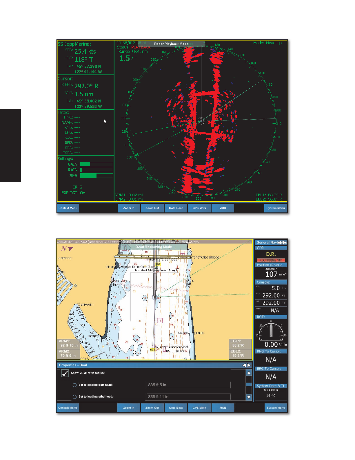
Dead Reckoning 91
To Enable Dead Reckoning 91
Moving the Boat in Dead Reckoning 91
10 - Data Manager 93
What is the Data Manager? 93
Data Collection 93
Nav Objects 94
Searching Nav Objects 95
Editing Nav Object Properties 96
Importing and Exporting Nav Objects 98
To Import Nav Objects 98
To Export Nav Objects 98
Charts 99
Chart Data Details 99
System Information 99
System Information Data Details 99
11 - ETA Management 101
ETA - No Active Route 102
ETA - Active Route 104
12 - Radar Management 105
Glossary for this Chapter 105
InSight Radar 2 - Black Box (IR2-BB) 105
What is the IR2-BB? 105
How Does the IR2-BB Work? 105
The Radar Window Pane 106
Closing and Opening 106
Ghost Cursor 106
Radar/Chart Overlay 107
Targets Panel 107
Radar Overlay and MARPA 107
How It Works 107
Radar Target Tracking 108
Point and Click Radar (MARPA) 108
Acquiring MARPA Targets 109
MARPA Symbology 109
Terms and Acronyms 110
Radar Configuration Options 111
Radar Tab 111
Target Tab 112
The Radar Context Menu 114
Range 114
Auto Range 114
Manual Range 114
Tuning 114
Adjusting the Gain 114
Reducing Sea Clutter (SEA) 115
Rain 115
Rejecting Radar Interference 116
Radar Properties 116
Initial Radar Setup 116
Radar Presets 117
About Radar 118
Options 118
Orientation 118
13 - Target Tracking 119
Target Types Supported 119
Targets Panel 119
Targets in Workboat Navigator 119
Prior to Setting Up Target Tracking 119
Targets Panel 121
Managing Target Appearance 121
Information On The All Targets List 123
River AIS 123
Passing Plan 124
Goto Pass Point 124
Target Detail 125
Goto Target 125
Messages 125
Voyage Data 126
Static Data 126
Temporarily Filtering Targets 126
Alarms 127
Changing Alarm Settings 129
To Change Alarm Settings for Targets 129
To Change Alarm Settings for XTE 129
AIS 130
Types of AIS 130
Naming Conventions For Targets 131
What Is AIS? 131
AIS Target Settings 131
AIS Targets in Workboat Navigator 132
AIS Broadcasts Workboat Navigator
Recognizes 133
14 - Tides & Currents 135
Tide Bars and Current Arrows 135
Interpreting Tide Bars 135
Interpreting Current Arrows 136
Chapter NameTable of Contents

viii
Jeppesen Workboat Navigator User’s Guide
Adjusting Current Arrow Size 136
Tides & Currents SysInfo Panel 137
The Tides & Currents Application 138
The Tides & Currents ToolBar 139
The Tides & Currents Graph 140
Weekly View and Daily Table 140
Changing the Date 140
Multiple Windows in Tides and Currents 141
Route Calculator 141
To Attach a Current Station to a Route 141
Calculating Best Departure Time 142
15 - Autopilot 143
Autopilot Connections 143
Settings 143
Definitions Of Autopilot Setting Options 144
Using the Autopilot On the Water 145
How to Use the Autopilot - Active Mark 145
How to Use the Autopilot - Active Route 145
Arrival Circle 145
Arrival Distance for Existing Marks 145
Changing Default Arrival Distance 145
Table of Contents
Glossary 146
Index 152
Hot Keys 156
Chapter Name
Table of Contents
1
1
1 - Introduction
Jeppesen Workboat Navigator
This User’s Guide covers information about the Jeppesen Workboat Navigator,
Jeppesen Marine's state-of-the-art navigation software package.
Jeppesen Workboat Navigator provides AIS integration, radar overlay and other key
marine solutions. These advancements offer significant benefits to your operation by
enhancing navigational accuracy along critical navigation areas and poor weather
and other low-visibility condition solutions. By providing seamless integration of
multiple charting tools and formats, Jeppesen Workboat Navigator makes it easy for
marine operators to remain knowledgeable and in control at all times.
Jeppesen Workboat Navigator is the result of many years of collaborative
development between Nobeltec marine navigation solutions and Jeppesen
avionics. This product was built leveraging the award-winning experience and
industry knowledge of a team of seasoned and talented pilots, captains, scientists,
engineers and programmers.
Workboat Navigator further serves as an electronic navigation data professional
information service. Regular subscriptions to this professional information service
provide you with the most recently updated, high quality charts and navigation
information available.
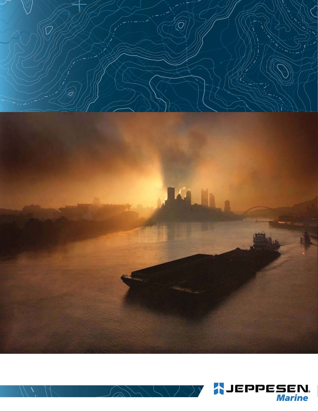
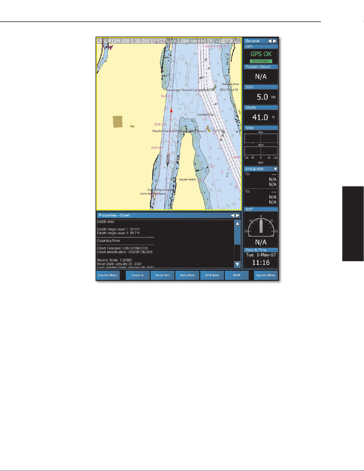
Screen Layout
As shown in Figure 1.1, Workboat Navigator is laid out simply, with easily-viewed
controls and large menu buttons. Additionally, Workboat Navigator screen layout
can be configured by the user with a tool called View Manager. Configuring screen
layout is discussed in further detail in Chapter 3 - Setting Up Workboat Navigator.
1 - Introduction
Figure 1.1 - Jeppesen Workboat Navigator Screen

2
Jeppesen Workboat Navigator User’s Guide
Professional+ Charts and NavData
Jeppesen Workboat Navigator comes with vector charts, planning and overview
raster charts, supplemental River Distance Markers and much more. This
combination of charts and data is collectively called NavData®.
NavData is copyright protected and can only be accessed if you have purchased a
license and received a Product Security Key (also called an “eToken”).
NavData is subdivided into regions for purchase and subscription purposes. Each
1 - Introduction
region is unlocked using a License File provided when the subscription begins. The
License File validates chart and data subscriptions.
Hardware Overview
The following hardware devices output information that Jeppesen Workboat
Navigator can recognize and integrate into on-screen display. All hardware products
must be powered on and connected to your computer in order for Workboat
Navigator to recognize them. See the Jeppesen Workboat Navigator Installer’s
Guide for software integration instructions.
GPS (required)
A GPS receiver uses information from GPS satellite signals to calculate your
position along with speed and direction. This information is transmitted to the
computer, where Jeppesen Workboat Navigator places a graphic display of your
boat at the transmitted location on the chart.
®
WARNING:
navigation when determining their position. Always use two or more methods
to guard against errors that put your boat in a dangerous situation.
Seasoned navigators know not to rely on a single method of
AIS/Target Tracking
Many Automatic Identification System (AIS) Transceivers are equipped to transmit
and receive all AIS NMEA sentences. Jeppesen Workboat Navigator intelligently
interprets and displays AIS target data in an easy-to-understand on-screen format.
Heading Sensor
A Heading Sensor produces highly accurate, stable readouts of your ship’s heading.
The Heading Sensor in conjunction with Jeppesen Workboat Navigator will provide
you with constant information about your ship’s attitude and rate of turn, as well as
your heading vs. Course Over Ground (COG).
Depth Sensor
Depth Sensors are utilized to sense how “deep” a body of water is from top to
bottom. Depth sensors may also be called pressure sensors. Depth sensors use
electronic and mechanical means to measure depth.
Sounder
A depth sounder provides target and bottom detail, as well as advanced features
such as dual frequencies, temperature display, range, gain, and shift settings.
Autopilot
Interfacing an autopilot with Jeppesen Workboat Navigator provides you with
easier route planning and more precise direction-based navigation options and
adjustments.

1 - Introduction
3
Wind Sensor/Anemometer
A sensor that monitors wind speed or wind speed and direction, and converts that
data into a digital output signal.
Radar and the IR2-BB
The Nobeltec® InSight Radar 2 - Black Box (IR2-BB)™ is a specially designed
hardware component that converts the analog output from most existing industrystandard radars into a digital stream that can be used by Jeppesen Workboat
Navigator.
Jeppesen Workboat Navigator provides you with the tools to view radar
transmissions received through the IR2-BB in a traditionally configured radar display
on-screen or overlaid directly on top of your electronic charts.
Limits of Electronic Navigation
Jeppesen Workboat Navigator is developed by skilled software engineers and
mathematicians. It undergoes rigorous safety and accuracy testing and quality
assurance before it is released to the public to use on the water. However,
occasional software issues or malfunctions could remain in the software. While
Jeppesen Marine makes every effort to identify and repair software issues if they
are discovered, this product is specifically not promised to be issue free.
Another limitation to complete accuracy is the status of your digital charts.
Electronic charts are made by skilled cartographers. However, some cartographic
surveys upon which digital charts are based were made over 50 years ago.
Therefore, it is possible for errors to occur in the final products.
1 - Introduction
4
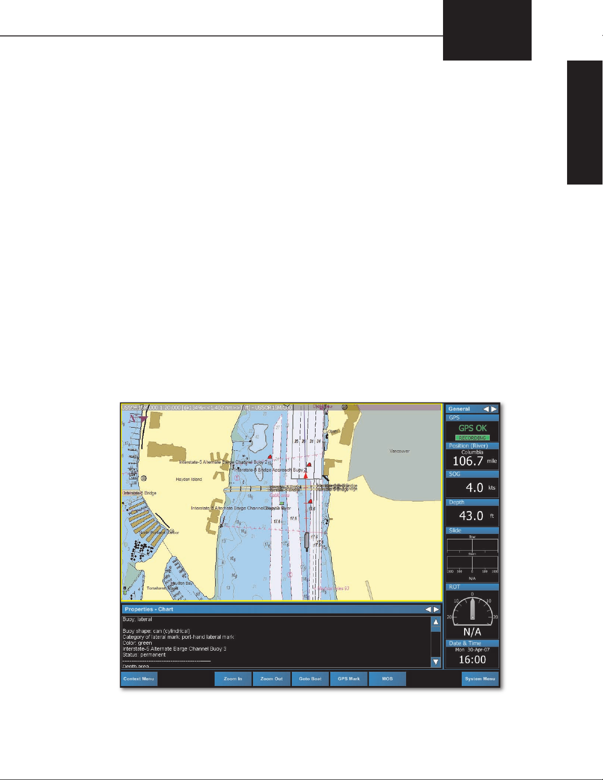
2 - Look & Feel
Jeppesen Workboat Navigator User’s Guide
NavInfo Window Pane
Chart Window Pane
SysInfo Window Pane
Main Toolbar
Figure 2.1 - Jeppesen Workboat Navigator Screen - Default View

2
2 - Workboat Navigator Look and Feel
Glossary for this Chapter
5
Active
Window
Pane
Chart
View
Window
Pane
View
Manager
Panel
The Active Window Pane is the window pane that currently has cursor
focus. This is indicated by a yellow border around the window pane. In
Figure 2.1, the Active Window Pane is the Chart window pane.
Jeppesen Workboat Navigator displays high-resolution vector charts
and raster charts.
Layout of available window panes in Jeppesen Workboat Navigator,
created using the View Manager. A View can contain one full-screen
window pane, such as Radar, or several window panes, such as Chart,
NavInfo, and SysInfo.
Each individual, available selection of content for the View. NavInfo,
Radar, Raster Charts, SysInfo, Vector Charts, and Video are each
available to be displayed in a Window Pane.
A component of Jeppesen Workboat Navigator used to establish up to
6 Views of charts and data. Users may wish to configure multiple Views
to allow them to utilize different components of the software.
NavInfo and SysInfo window panes are divided into multiple static
panels of content. For example, Target List and Target Details are two
of the available panels in the SysInfo window pane; COG and ROT are
two of the available panels in the NavInfo window pane.
Workboat Navigator Window Panes
There are five available types of Workboat Navigator Window Panes. All content
that is available through Jeppesen Workboat Navigator can be displayed using the
window pane layout conventions of the software. Each window pane is dedicated to
a particular type of data.
Specific system configurations (or “Views”) can be set up and customized using the
View Manager. View Manager controls how Workboat Navigator content appears
by allowing the users to arrange the different Workboat Navigator Window Panes.
See Chapter 3 - Setting Up Workboat Navigator for information on using the View
Manager.
2 - Look & Feel
Default View
Jeppesen Workboat Navigator by default uses a View containing Chart, NavInfo and
SysInfo window panes (see Figure 2.1). Certain events, such as pressing the MOB
button or a system alarm will cause Workboat Navigator to revert to the default
view. Use the 6 key or System Menu | Next View to toggle between views.
6
2 - Look & Feel
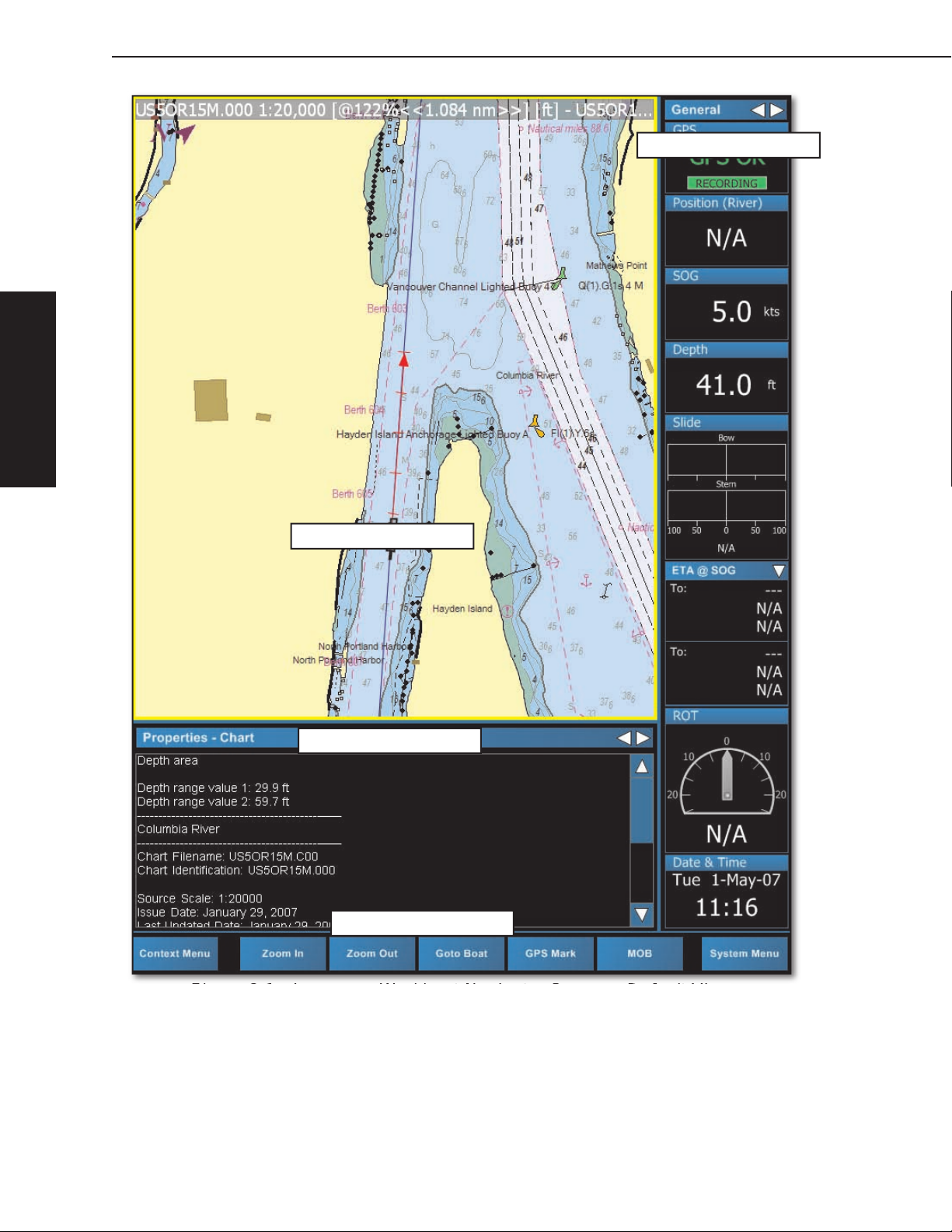
Jeppesen Workboat Navigator User’s Guide
Figure 2.2 - Workboat Navigator Single Content View - Radar Window Pane
Figure 2.3 - Multiple Content View - Three Window Panes (Default View)
2 - Workboat Navigator Look & Feel
Chart Window Pane
The section in the divided windowpane layout of Jeppesen Workboat Navigator
devoted to displaying and manipulating Vector and Raster charts. This is the
window pane that displays the Chart, Boat, and Nav Objects such as Marks and
Routes.
Figure 2.4 shows a Vector chart full-screen window pane on the left and a Raster
chart full-screen window pane on the right.
Figure 2.4 - Chart Window Pane: Vector and Raster Charts
7
2 - Look & Feel
NavInfo Window Pane
The Navigation Information (NavInfo) window pane contains all sensor-tracked data,
such as GPS, Speed Over Ground, Course Over Ground, Heading, etc. Data from
those sensors is displayed in data panels that cannot be edited.
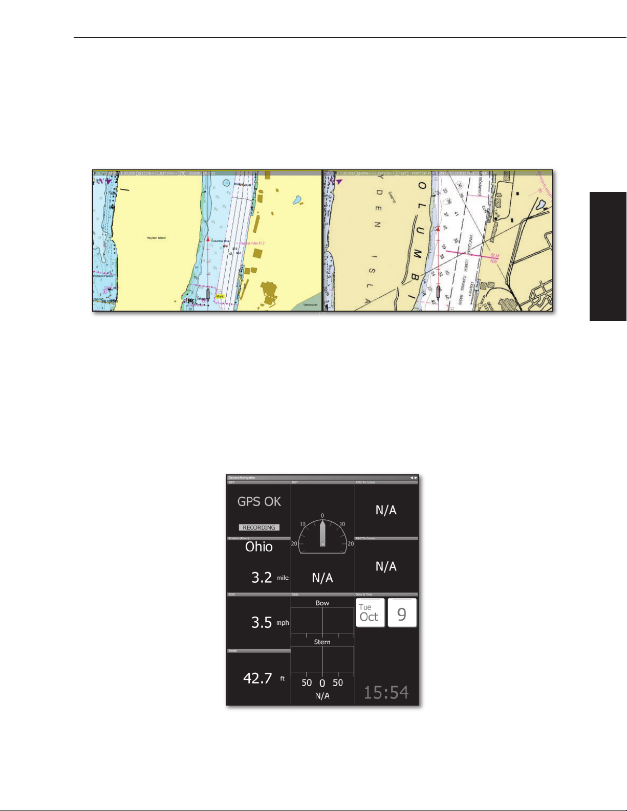
Figure 2.5 shows the General Navigation 1 layout for the NavInfo pane. Available
options for this window pane are General Navigation 1, General Navigation 2 and
Active Navigation.
Figure 2.5 - NavInfo Window Pane: General Navigation 1 Layout

8
2 - Look & Feel
Jeppesen Workboat Navigator User’s Guide
SysInfo Window Pane
The section in the divided windowpane layout of Jeppesen Workboat Navigator
devoted to providing system information and managing various features of the
program, such as Target AIS information, Man Overboard tracking, Chart and Object
Properties, Status Messages, and Data Playback.
Figure 2.6 - SysInfo Window Pane: Properties Panel
Radar Window Pane
The section in the divided window pane layout of Jeppesen Workboat Navigator
devoted to providing Radar data. This data can be viewed in a multiple-paned
layout, or a single, full-screen window pane that simulates a radar plotter.
Figure 2.7 - Radar Window Pane
2 - Workboat Navigator Look & Feel
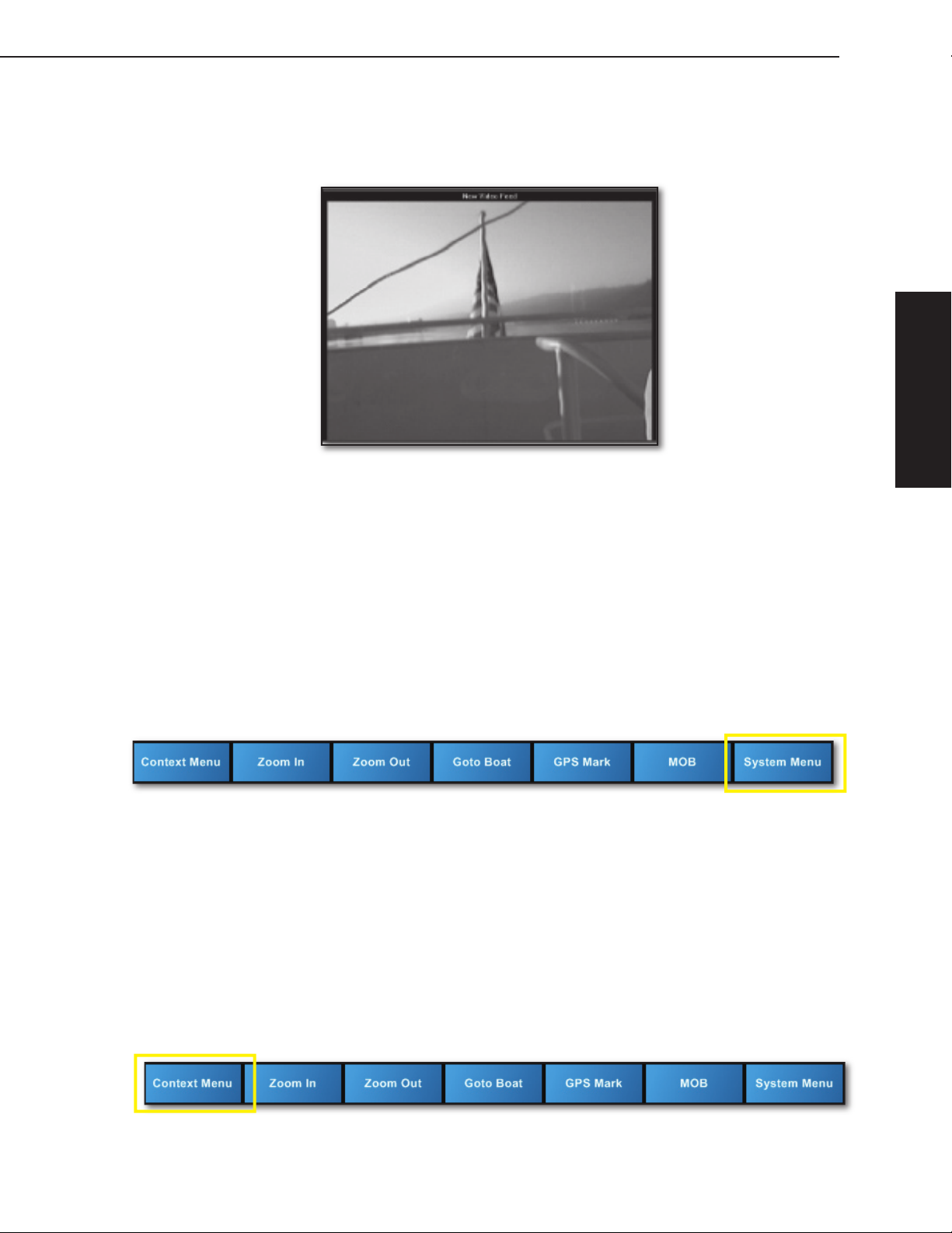
Video Window Pane
The section in the divided windowpane layout of Jeppesen Workboat Navigator is
devoted to providing video camera display. Workboat Navigator can use video feed
from a number of cameras placed on board a vessel.
Figure 2.8 - Video Window Pane
9
2 - Look & Feel
Workboat Navigator Main Toolbar
The Workboat Navigator Main Toolbar contains seven buttons and is located at the
bottom of the View at all times. This toolbar allows you to view all menus, zoom in
and out, focus controls on your boat, and provides you with the ability to instantly
raise a Man Overboard alarm if necessary. Figure 2.9 shows the main toolbar as it
appears at the bottom of the application.
System Menu Button
The System Menu Button opens the System Menu and provides access to a variety
of system and on-screen functions, such as the View Manager. The System Menu
collapses when not in use. 9 also opens this menu.
Figure 2.9 - Workboat Navigator Main Toolbar: System Menu Button
Context Menu Button
The Context Menu button opens a dynamic Context Menu for the current active
Chart or Radar window pane. Context menus can also be used to create and
control specific Nav Objects, such as Boat, Marks, Waypoints, and so forth.
Context menus are dynamically specific to window focus. Content of the menus
change depending on which window pane has focus. For example, when the Chart
window pane has focus, the Context menu will populate with controls for that
window. Like the System Menu, the Context Menu collapses when not in use.
The Context Menu is disabled when the active window pane is the NavInfo, SysInfo
or Video window panes, which do not have menu controls.7also opens this menu.
Figure 2.10 - Workboat Navigator Main Toolbar: Context Menu Button
10
2 - Look & Feel
Jeppesen Workboat Navigator User’s Guide
NOTE:
There are also right-click Context Menus, used to control on-screen
objects, such as Boat, Marks, Waypoints, etc. For example, when the Boat
has focus, the right-click Context Menu contains options for the Boat only.
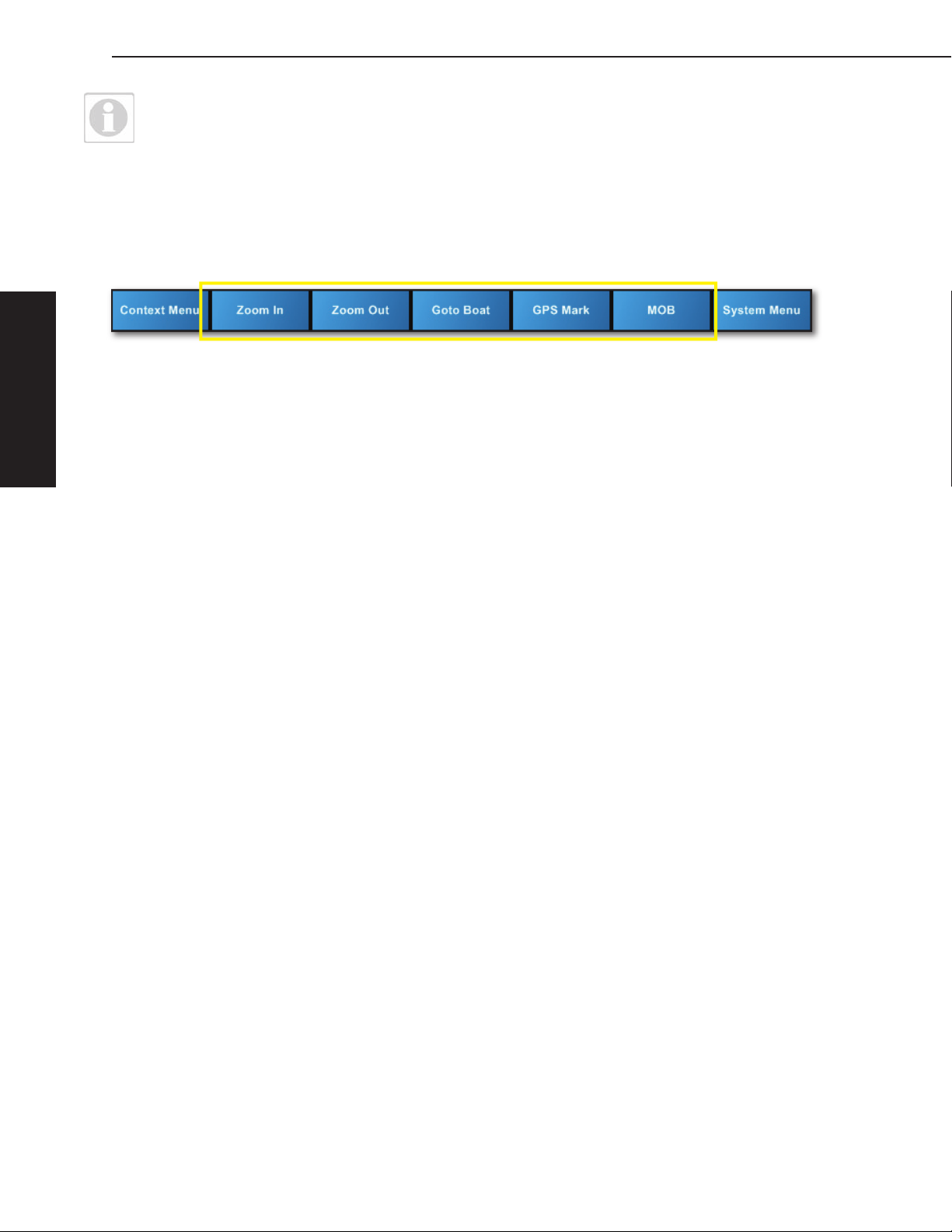
Other Main Toolbar Buttons
The remaining buttons on the Main Toolbar control some of the most common
functions performed by the user. These buttons consist of: Zoom In, Zoom Out,
Goto Boat, GPS Mark and MOB.
Figure 2.11 - Workboat Navigator Main Toolbar: Other Buttons
Zoom In/Zoom Out Buttons
The Zoom buttons control the scale of the chart displayed in the Chart window
pane. You can Zoom In and Out on the chart window pane using Zoom In and
Zoom Out Main Toolbar buttons or the + and - keys on your keyboard. If your
mouse has a wheel, you can also use the mouse wheel to zoom in (wheel up) or
zoom out (wheel down).
Goto Boat Button
Click this button to refocus the chart on the boat. This button automatically changes
chart orientation to Course Up and the Autoscroll mode to Look Ahead. W also
performs this function.
GPS Mark Button
Click this button to immediately place a Mark on the Chart window pane directly
under the boat’s current position based on GPS location. 5 also performs this
function.
MOB Button
This button adds a Man Overboard (MOB) mark to the Chart window pane at the
current transmitted boat location based on GPS location, and immediately changes
focus to the SysInfo window pane, MOB panel. 4 also performs this function.

3
3 - Setting Up Workboat Navigator
This chapter provides an overview of two of the basic tools used to set up Jeppesen
Workboat Navigator for use specific to your boat. There are other setup options
that are meant to be performed by a certified marine technician during installation
or update of Jeppesen Workboat Navigator. See the Jeppesen Workboat Navigator
Installer’s Guide for more technical setup information.
Boat Setup
The Boat Properties window (System Menu | Boat Properties) is where you set
up the boat displayed on-screen to match your current configuration. When you
open this window, the existing or default settings appear. Displayed Standard Boat
Properties cannot be edited using the Boat Properties window, but are configured
during system installation.
Standard Boat Properties include Boat Name/ID, Length, Width, Draft, Air Draft,
GPS Bow Offset and GPS Port Offset.
GPS Bow Offset is the distance from the bow of your boat to the location of the
•
GPS antenna.
GPS Port Offset is the distance from the port of your boat to the location of the
•
GPS antenna.
11
NOTE:
Refer to the Jeppesen Workboat Navigator Installer’s Guide or
contact your Workboat Navigator Deployment Specialist to make any
customized changes to your Standard Boat Properties.
From the Boat Properties window, click Edit Model to edit your boat configuration.
Boat Model Presentation
The Boat Model panel allows you to configure how the boat displays. For more
detail, see Boat Properties in this chapter. This panel is where you select the type
of Boat you are using.
The Use Boat Model drop-down list allows you to select from
•
a list of boat and tow layout configurations. If you are using
Workboat Navigator for coastal waters, select Standard Vessel
from the drop-down list (see Figure 3.1).
If you are using Workboat Navigator to tow barges during inland
navigation, you can use the following features to configure your tow
model:
Click New Model... to create a new Tow Model.
•
Click Edit Model... to edit the Tow Model.
•
Model Name. Input a customized name for the current tow
•
configuration. The maximum is 64 characters.
Delete Model. Removes the selected Boat Model from the Use
•
Boat Model drop-down list. This is a permanent deletion and
cannot be undone.
Boat offset from Port. Input the distance from the port edge of
•
the tow to the port edge of the boat. Click
Boat Model graphic after you update the Boat offset from Port.
This tool is used for tow boat barge configuration.
Center Boat - Click to center the boat to the tow.
•
to redraw the
J
Figure 3.1 -
Standard Vessel
3 - Setting Up
NOTE:
You cannot delete the Standard Vessel and Tow Boat Vessel from the
list. These will be used as the boat when you create a new model.
12
Jeppesen Workboat Navigator User’s Guide
Tow Model Window
Use the Tow Model window to configure or edit the Tow layout to
your current configuration. The more accurately you input your tow
data, the better Jeppesen Workboat Navigator will display the outline
of your boat shape on the chart.
The Tow Model graphic displayed is a to-scale illustration of the way
your tow is configured in Jeppesen Workboat Navigator. This graphic
is updated whenever you make changes to the configuration.
Layout is shown using rectangular barge graphics.
Barge List
The Barge List contains all current barge types available to add
to your tow configuration. Tow configuration is divided into "strings"
which are numbered sequentially from Port to Starboard.
Incremental adjustments to each Barge can be made by selecting an existing Barge
with your mouse and then using the Adjust Forward, Aft, Port and Starboard feet
and inches and radio buttons to the left of the graphic.
Once you have set up your Barge List, use the Refresh button to redraw the
•
Tow Model Graphic and verify that your changes have been incorporated.
To remove a Barge, click on the Barge and then click Remove Selected.
•
To clear the screen and start again, click Remove All.
•
3 - Setting Up
Figure 3.2 - Tow Model Configuration
3 - Setting Up Workboat Navigator
To Add Barges to the Tow Model
Select the barge type to add from the list provided.
1.
Select the Add Barge to String radio button and select the string to add this
2.
barge to, see String label at bottom of Tow Model Graphic for placement.
Select the Add port hip barge or the Add starboard hip barge radio button.
3.
Click Add to Model.
4.
Click OK to save your Tow Model settings and return to Boat Properties.
5.
Figure 3.3 - Add a Barge to a String
To Add a Hip Barge
In the Tow Model window, highlight a barge type.
1.
Click Add Port/Starboard Hip Barge.
2.
Click Add to Model.
3.
The selected barge will be added to the Tow Model graphic parallel to your boat
4.
at Port or Starboard.
13
3 - Setting Up
14
Jeppesen Workboat Navigator User’s Guide
To Move a Barge
Click on the Barge you wish to move.
1.
Click the radio button next to Adjust...(Forward, Aft, Port, or Starboard).
2.
Input the feet and inches you wish to move the Barge (use the format: ff in). Or
3.
type the total number of inches. Workboat Navigator automatically converts total
inch value to feet and inches.
Click Refresh to update the Tow Model graphic.
4.
3 - Setting Up
Figure 3.4 - Tow Model Graphic
To Remove a Barge
Click on the Barge you wish to remove.
1.
Click Remove Selected.
2.
NOTE:
If you make incorrect adjustments to a tow model, an error message appears
asking if you would like the software to automatically correct the Tow Model.
After you make all changes in the Tow Model window, click OK to save your Tow
3.
Model settings and return to Boat Properties.

3 - Setting Up Workboat Navigator
Boat Context Menu
The Boat Context Menu is accessed by right-clicking on the Boat or you can leftclick the Boat and then click the Context Menu button from the Main Toolbar.
The Context Menu allows you to view and edit specific features of the Boat. The
following are all available options in the Boat Context Menu:
Properties. Opens the SysInfo window pane, Properties panel for the boat.
•
Dead Reckoning. Turns Dead Reckoning on or off.
•
Reset XTE. Reset the cross track error value to zero for the active route.
•
15
3 - Setting Up
16
Jeppesen Workboat Navigator User’s Guide
The View Manager
What is the View Manager?
The View Manager tool customizes how Jeppesen Workboat Navigator screens
are laid out and allows you to control how and what you view within Workboat
Navigator.
View Manager is accessed using the System Menu (System Menu | Tools/
Settings | View Manager).
View Manager establishes how Jeppesen Workboat Navigator displays charts and
other data. This customized layout of charts and data, also called a "View", can be
configured to display one content type at a time, or be divided into multiple window
panes, each pane containing a different content type (see Figures 3.5 and 3.6).
Once you have configured your Jeppesen Workboat Navigator View preferences,
use the 6 Hot Key or System Menu | Next View to cycle through all configured
Views.
TIP:
To work with one chart in multiple locations, set up a split screen View
and place the same chart type (Vector or Raster) in each window pane.
Default View
Jeppesen Workboat Navigator by default uses a View containing Chart, NavInfo and
SysInfo window panes (see Figure 3.5). Certain events, such as pressing the MOB
button or a system alarm will cause Workboat Navigator to revert to the default
view. Use the 6 key to cycle through views.
3 - Setting Up
Figure 3.5- Workboat Navigator Single
Content View - Radar Window Pane
Figure 3.6 - Jeppesen Workboat
Navigator Multiple Content - Default View
3 - Setting Up Workboat Navigator
Setting Views With View Manager
The View Manager controls how the content of all Jeppesen Workboat Navigator
window panes is laid out. Up to six (6) layout templates or “Views” can be edited.
Use View Manager to determine what content displays in all window panes of a
View. For example, you may wish to have one View that displays a SysInfo window
pane, NavInfo window pane, and a Chart window pane, and another View that
displays only Radar. The View Manager helps you set up each configuration.
To Configure Views and Layouts
Click System Menu | Tools/Settings | View Manager.
1.
Monitor Configuration: if there are two monitors connected to your computer,
2.
select the right or left monitor to enable or disable that monitor, then click on a
monitor to set that monitor’s layout. See Figure 3.7.
17
Figure 3.7 - View Manager - Monitor Configuration - Two Monitors
One Landscape, One Portrait shown
Select and Configure Layout: There are six possible View configurations. The
3.
upper left configuration is the default. Each established View is monitor-specific.
3 - Setting Up
Figure 3.8 - View Manager - Select and Configure a Layout: Monitor #
Select a View configuration and click Edit to open the Select a Layout window
4.
and edit the existing layout.

18
Jeppesen Workboat Navigator User’s Guide
From the Select a Layout window, choose a configuration template, consisting
5.
of one to six panes in various layout configurations. Click on a configuration
template to open Edit the Layout.
Figure 3.9 - Select a Layout
Edit the Layout: This window is where you determine which type of data is
5.
placed in each window pane. The active pane is surrounded by a yellow border.
Select the data type for each window pane by clicking on a chart or data type
in the right-hand list (Vector Chart, Radar, NavInfo, Raster Chart, Video, or
SysInfo). Once the data type has been determined for a window pane, focus will
automatically shift to the next window pane. If a data type is not available for a
particular window pane, it will not be available for selection.
3 - Setting Up
Figure 3.10 - View Manager - Edit the Layout
After you have selected all content types, the Select and Configure Layout
7.
window opens.
Repeat steps 3-7 for up to six views.
8.
Click Done when you are finished with View configurations. To cycle through
9.
each configuration use System Menu | Next View or the 6 hot key.
3 - Setting Up Workboat Navigator
19
Figure 3.11 - Workboat Navigator - Portrait Mode
Portrait Mode
Workboat Navigator supports portrait mode. This mode is commonly used by river
operators where a vertical aspect ratio allows more river to be seen at once.
This User’s Guide does not include details about how to set up Portrait Mode. For
that information, please see the documentation that came with your monitor and
operating system.
3 - Setting Up

20
Jeppesen Workboat Navigator User’s Guide
3 - Setting Up
4
4 - The System Menu
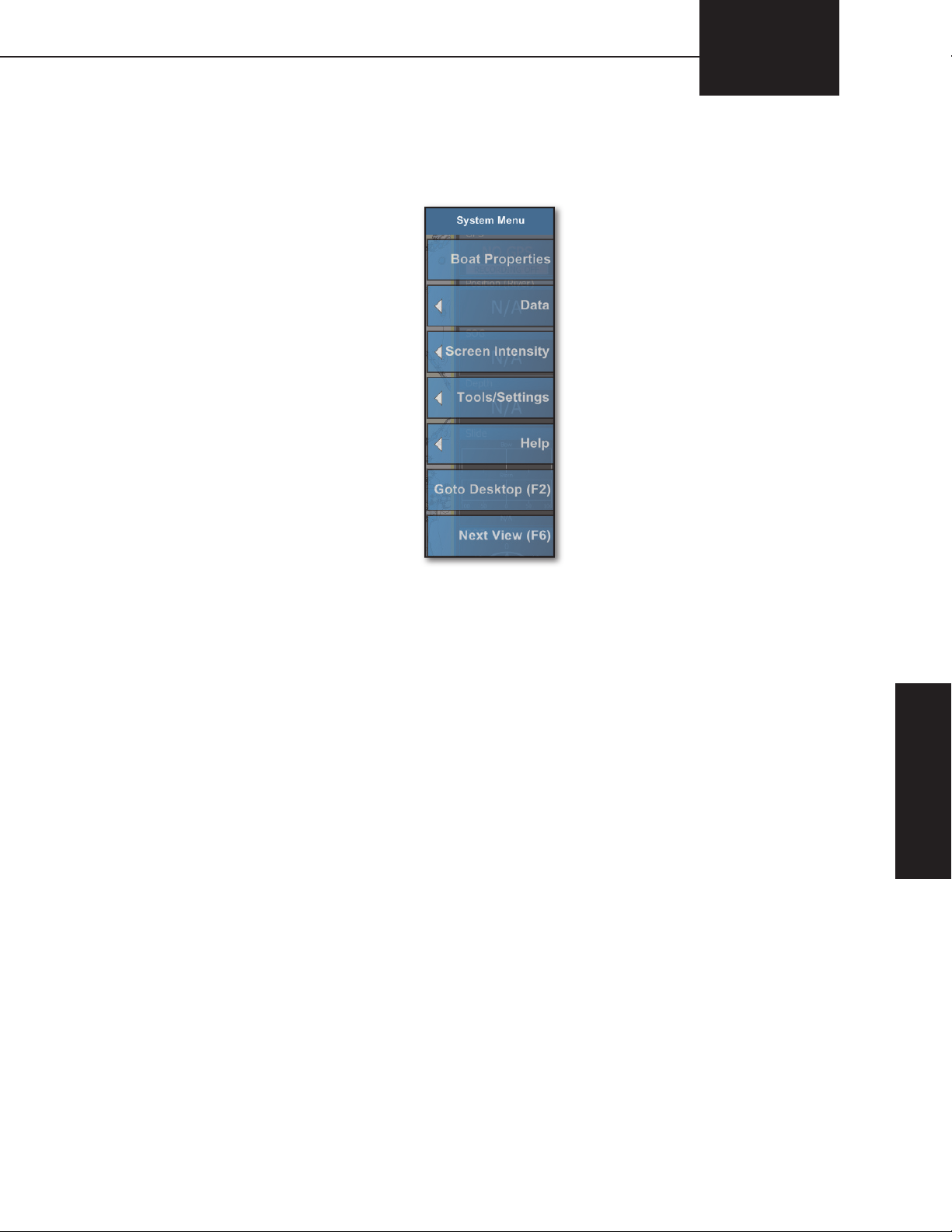
Use the System Menu to access a variety of system and on-screen functions, such
as the View Manager and Boat Properties. This menu is where you control larger
functions of Jeppesen Workboat Navigator. The System Menu collapses when not
in use.
21
Figure 4.1 - The System Menu
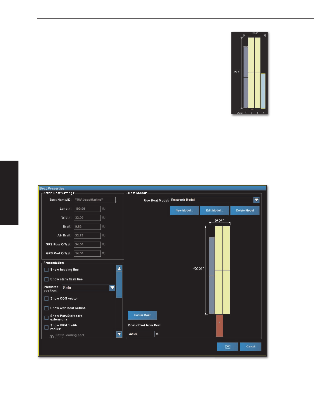
Boat Properties
The Boat Properties window is where you view and configure your boat. When
you open this window, the current or default settings appear. Displayed Static Boat
Settings cannot be edited from this window. See the Workboat Navigator Installer’s
Guide to edit Static Boat settings.
From the Boat Model group, click Edit Model to edit your boat configuration.
Standard Boat Properties include Boat Name/ID, Length, Width, Draft, Air Draft,
GPS Bow Offset and GPS Port Offset.
GPS Bow Offset is the distance from the bow of your boat to the location of the
•
GPS antenna.
GPS Port Offset is the distance from the port of your boat to the location of the
•
GPS antenna.
Boat Presentation Settings
Show Heading Line. Heading Line indicates the heading of the boat and originates
from the GPS transmitted position, extending 15 miles. The direction of the heading
line is based on input from the heading sensor. If no heading input is detected, the
Heading Line is based on the COG value. Default setting for this option is On.
Show Stern Flash Line. The Stern Flash Line is drawn 180 degrees from the
Heading Line, and also originates from GPS position, extending 15 miles. The
direction of the Stern Flash Line is based on input from the heading sensor. If no
heading input is detected, the Stern Flash Line is based on the COG value. Default
setting for this option is On.
4 - The System Menu
4 - The System Menu

22
Jeppesen Workboat Navigator User’s Guide
Heading Line
Stern Flash Line
Figure 4.2 - Heading Line/Stern Flash Line
Predicted Position. Use this drop-down menu to select the amount of time you
want represented by the COG vector and the boat outline. The following fields are
affected by this setting:
Show COG vector
•
Show With Boat Outline
•
Show COG Vector. The COG Vector is an arrow that extends from the GPS
transmitted position. Its length is determined by combining the SOG and predicted
position time. Predicted position time will be indicated by hash marks in one minute
intervals. The direction of the vector is based on the GPS position. Default setting
for this option is On.
Boat outline
COG vector
4 - The System Menu
Figure 4.3 - COG Vector
Show With Boat Outline. Place a check-mark in this check box to display an
outline of the boat on the chart using the time entered in the predicted position.
The outline includes rate of turn and may indicate a different position than the COG
vector. The default setting is for this option is Off.
Show Port/Starboard extensions. This check box turns on or off the display of the
port and starboard side extension lines. Default setting for this option is Off.
Show VRM 1/VRM 2 with radius. The Variable Range Marker (VRM) is a range
ring or series of rings that surround the boat. VRM are normally used to measure
distances to targets.
 Loading...