

Page 1

FEATURES
True to the Music
True to the Music
2
43
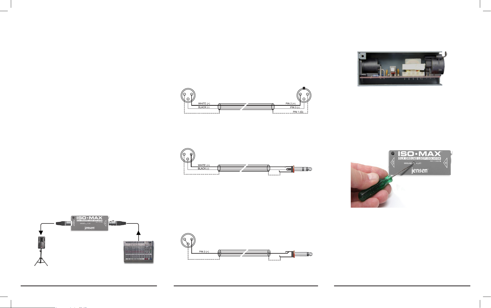
1. XLR IN: Connects from the device you would like to isolate.
2. XLR OUT: Connects to your PA or recording system.
3. GROUND LIFT: Disconnects PIN-1 on the XLR - the audio ground
at the outputs to eliminate hum and buzz created by ground loops.
4. STEEL CASE: Virtually indestructible steel case for toughness
and reliability on the road. Protects the audio circuit from
electromagnetic and radio interference. Durable power-coat nish
for years of long life.
5. HD JACKS: Heavy duty glass reinforced nylon XLR connectors
are bolted to the steel case for durability.
6. RF FILTER: Passive lter blocks radio frequency interference
from bleeding into audio lines.
7. TRANSFORMER: Isolates the audio between the input and output
to eliminate hum and buzz.
8. HEAVY DUTY PCB: Double sided PCB mounts to a rigid 14-gauge
steel L-frame for long life.
6 7
8
GLX Ground Loop Isolator GLX Ground Loop Isolator
Jensen ISO-MAX
5
®
1
GLX SPECIFICATIONS
Audio circuit type: ............................................................................................Passive
Frequency response: ............................................................... 20Hz - 20KHz +/-1 dB
Total harmonic distortion (THD+N): ............................... <0.0006% 1KHz -10dBu Out
Dynamic range: ...............................................................................................>135dB
Input impedance: ........................................................................8.66K With 10K load
Maximum input: ...............................................................................................+25dBu
Gain: .................................................................... +.25dB/-5.7dB 10K/600 Ohm Load
Clip level: .........................................................................................+25dBu at output
Output impedance: ......................................................................................600 Ohms
Equivalent input noise: .................................................................................... 110dBu
Noise oor: ...................................................................................................... 110dBu
Intermodulation distortion: .............................................................0.002% -10dBu out
Common Mode Rejection: .................................................................................-84dB
To meet the requirements of California Proposition 65, it is our responsibility to inform you of the following:
WARNING: This product contains chemicals known to the State of California to cause cancer,
birth defects or other reproductive harm.
Please take proper care when handling and consult local government regulations before discarding.
RADIAL ENGINEERING 3 YEAR
TRANSFERABLE LIMITED WARRANTY
RADIAL ENGINEERING LTD. (“Radial”) warrants this product to be free from defects in material and
workmanship and will remedy any such defects free of charge according to the terms of this warranty.
Radial will repair or replace (at its option) any defective component(s) of this product (excluding nish and
wear and tear on components under normal use) for a period of three (3) years from the original date of
purchase. In the event that a particular product is no longer available, Radial reserves the right to replace
the product with a similar product of equal or greater value. In the unlikely event that a defect is uncovered,
please call 604-942-1001 or email service@radialeng.com to obtain a RA number (Return Authorization
number) before the 3 year warranty period expires. The product must be returned prepaid in the original
shipping container (or equivalent) to Radial or to an authorized Radial repair center and you must assume
the risk of loss or damage. A copy of the original invoice showing date of purchase and the dealer name
must accompany any request for work to be performed under this limited and transferable warranty.
This warranty shall not apply if the product has been damaged due to abuse, misuse, misapplication,
accident or as a result of service or modication by any other than an authorized Radial repair center.
THERE ARE NO EXPRESSED WARRANTIES OTHER THAN THOSE ON THE FACE HEREOF
AND DESCRIBED ABOVE. NO WARRANTIES WHETHER EXPRESSED OR IMPLIED, INCLUDING
BUT NOT LIMITED TO, ANY IMPLIED WARRANTIES OF MERCHANTABILITY OR FITNESS FOR
A PARTICULAR PURPOSE SHALL EXTEND BEYOND THE RESPECTIVE WARRANTY PERIOD
DESCRIBED ABOVE OF THREE YEARS. RADIAL SHALL NOT BE RESPONSIBLE OR LIABLE FOR
ANY SPECIAL, INCIDENTAL OR CONSEQUENTIAL DAMAGES OR LOSS ARISING FROM THE USE
OF THIS PRODUCT. THIS WARRANTY GIVES YOU SPECIFIC LEGAL RIGHTS, AND YOU MAY ALSO
HAVE OTHER RIGHTS, WHICH MAY VARY DEPENDING ON WHERE YOU LIVE AND WHERE THE
PRODUCT WAS PURCHASED.
Jensen ISO-MAX
®
Jensen Transformers.
1588 Kebet Way, Port Coquitlam BC V3C 5M5
tel: 604-942-1001 • fax: 604-942-1010
info@radialeng.com • www.jensen-transformers.com
ISO-MAX® GLX User Guide - Part No. R870 1207 00 • © Copyright 2014 all rights
reserved.
Jensen is a division of Radial Engineering Ltd.
jensen-transformers.com
GLX GROUND
LOOP ISOLATOR
USER GUIDE
Specications and appearance are subject to change without notice.
Page 2
Thank you for purchasing the Jensen GLX ground loop isolator. The GLX is
RING (-)
SLEEVE (G)
1 2
3
SHIELDED TWISTED PAIR CABLE
DRAIN (G)
RING (-)
TIP (+)
SLEEVE (G)
12
3
1 2
3
1 2
3
1 2
3
TIP (+)
SLEEVE (G)
SHIELDED TWISTED PAIR CABLE
SHIELDED TWISTED PAIR CABLE
SHIELDED TWISTED PAIR CABLE
DRAIN (G)
DRAIN (G)
DRAIN (G)
the perfect problem-solver for the AV technician and audio engineer because
it will eliminate hum and buzz caused by ground loops in an audio system
by simply inserting it into the signal path. The GLX is fast to deploy and has
excellent audio properties that won’t introduce harsh distortion, excessive
phase shift or limit the bandwidth.
Although the GLX is designed to be plug & play easy to use, please take a
minute to read this short manual. It will give you insight on how to use the GLX
to get the most out of it. If you nd yourself asking questions after reading
the guide we suggest you visit the GLX FAQ page on the Radial web site.
This is where we post questions from users and inform you of updates. If you
still do not nd what you are looking for, we invite you to send us an email at
info@radialeng.com and we will do our very best to answer you in short order.
OVERVIEW
The GLX has been designed to provide isolation between two line-level
devices such as between mixing consoles, remote speakers, crossovers or
amp-racks. Use the GLX anywhere the source and destination devices may
cause system noise due to different ground potentials (often referred to as
ground loops) and stray DC voltages.
So called ground loops can introduce a 60 cycle hum in the sound system
and other noise. Although there are various solutions that can be engineered
to eliminate noise, the simplest and most effective is to isolate the source
and destination with an audio transformer.
The GLX employs a high-quality transformer to isolate the input from
the output while blocking stray DC currents that cause hum. The GLX is
engineered to handle any buffered line-level signal up to about +15dB with
very low distortion and exceptionally linear frequency response from 20Hz
to 18kHz.
The GLX is inserted in between a source device (like a mixer) and a destination
device (like a powered speaker). The XLR female input accepts a line-level
signal from the source device and the XLR male output sends the balanced
signal to the destination.
XLR-M OUT
DESTINATION
®
POWERED SPEAKER
Jensen ISO-MAX
XLR-F IN
GLX Ground Loop Isolator GLX Ground Loop IsolatorGLX Ground Loop Isolator
SOURCE
MIXING CONSOLE
MAKING CONNECTIONS
Before inserting the GLX into your signal chain, make sure all levels are turned
down. This will avoid power-on and connection transients that could cause a
loud pop in the sound system and damage more sensitive components such as
tweeters. The GLX is a passive device. This means that it does not require an
external power source to make it work. As soon as you plug it in, it will spring to life.
BALANCED CABLES
You can connect balanced devices to and from the GLX using standard XLR
cables. The GLX is wired following the AES convention with pin-1 ground, pin-2
(+), and Pin-3 (-).
SOURCEGLX
1 2
3
DRAIN (G)
SHIELDED TWISTED PAIR CABLE
12
3
If your source device uses balanced ¼” TRS connectors you can use a balanced
TRS to XLR adaptor cable wired as shown in the diagram below.
GLX
1 2
3
DRAIN (G)
SHIELDED TWISTED PAIR CABLE
RING (-)
SLEEVE (G)
SOURCE
UNBALANCED CABLES
You can also connect an unbalanced device such as a CD player to the using
an adapter cable. This will reduce the signal amplitude by roughly 6dB but for
high output devices like CD players and DJ mixers this is usually not a problem.
Simply increase the gain at the destination mixing console to compensate. The
GLX will convert the signal to balanced and you can use standard XLR cables
from the GLX output to the destination mixing console.
GLX
1 2
3
SHEILD (G)
COAXIAL CABLE
SLEEVE (G)
SOURCE
TIP (+)
Once the connections are made, slowly increase the volume to test. It is a good
idea to always test the audio system at low volumes. This will further prevent
system damage should a cable or connection be faulty.
Jensen ISO-MAX
®
ABOUT TRANSFORMERS
The GLX employs a high performance isolation transformer to ensure the
best signal transfer. However, not all transformers are of equal quality. At
Jensen, we take great care in engineering the best transformer for the job
and spend hours listening to the results.
Inside view
The transformer inside the GLX sounds great and does a superb job at
providing isolation from noise caused by ground loops. Note that because the
transformer will block all forms of DC, it will also block 48V phantom power
coming from the console. Phantom power will not harm the GLX.
LIFTING THE GROUND
The only control on the GLX is a GROUND LIFT switch. This switch is
recessed to prevent accidental use during operation. Use a small screwdriver
to access the switch.
Using the recessed switch
When the switch is set to the outward position, the signal ground from the
input to the output is connected via pin-1 at the XLR jacks. When pushed in,
the signal ground connection is ‘lifted’ on both sides by disconnecting pin-1
at the XLR jacks. This further isolates the source and destination devices
and generally results in less noise.
If, after connecting, you hear noise such as hum and buzz try pushing the
GROUND LIFT switch inward. Lifting the grounds can be useful when the
source and destination devices derive their AC power from different circuits
of the AC electrical mains leading to a potential ground loop.
Jensen ISO-MAX
®
 Loading...