

JENN-AIR JMC1150WS, AMC6158BAW, AMC6158BAS, AMC6158BAB, UCTK30WT Installation Instructions
...Page 1
MICROWAVE OVEN BUILT-IN TRIM KIT
INSTALLATION INSTRUCTIONS
Built-In Trim Kit Models UCTK27, UCTK30
UL listed for use over built-in electric ovens:
27 (68.6 cm): MEW5527, MEW6527
30 (76.2 cm): MEW5530, MEW6530, AEW3530, AEW4530, JJW8130DD, JJW8330DD, JJW9130DD, JJW9330DD
Table of Contents
MICROWAVE OVEN SAFETY ..................................................1
INSTALLATION INSTRUCTIONS.............................................1
Tools and Parts ...................................................................... 1
Location Requirements..........................................................2
Trim Kit Frame .......................................................................2
Minimum Cutout Dimensions................................................. 2
MICROWAVE OVEN SAFETY
Your safety and the safety of others are very important.
We have provided many important safety messages in this manual and on your appliance. Always read and obey all safety
messages.
This is the safety alert symbol.
This symbol alerts you to potential hazards that can kill or hurt you and others.
All safety messages will follow the safety alert symbol and either the word “DANGER” or “WARNING.”
These words mean:
Electrical Requirements ..........................................................2
Microwave Oven Preparation .................................................3
Bottom Duct Assembly...........................................................3
Microwave Oven Installation...................................................4
Install Top and Bottom Brackets ............................................4
Install Trim Kit Frame ..............................................................4
You can be killed or seriously injured if you don't immediately
DANGER
WARNING
All safety messages will tell you what the potential hazard is, tell you how to reduce the chance of injury, and tell you what can
happen if the instructions are not followed.
follow instructions.
can be killed or seriously injured if you don't
You
instructions.
INSTALLATION INSTRUCTIONS
Tools and Parts
Tools Needed
Gather the required tools and parts before starting installation.
Read and follow the instructions provided with any tools
listed here.
■ Measuring tape
■ Pencil
■ Phillips screwdriver
■ Drill
■ 7/64" drill bit
■ Ta pe
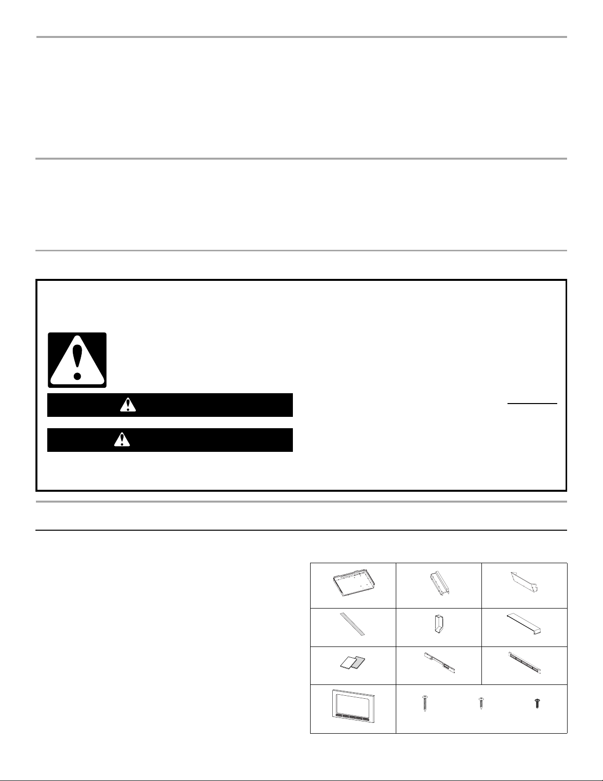
Parts Supplied
Duct base Bottom duct Rear duct bracket
Aluminum tape Rear duct Upper duct
2
1
Templates 1 and 2 Top bracket Bottom bracket
follow
W10308504A
Trim kit frame
13/16" screws 9/16" screws 1/2" screws
(2) (16) (4 - painted)
Page 2
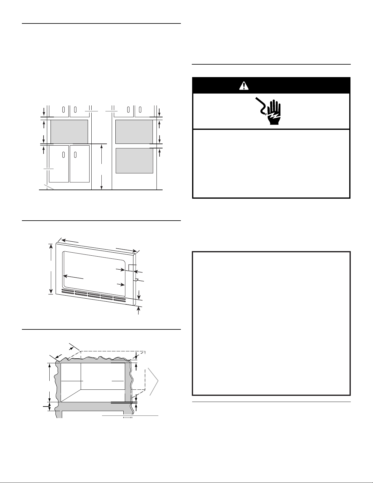
Location Requirements
The microwave oven may be installed over a built-in oven. If
installing over a built-in oven, make sure there is a minimum of 3"
(7.6 cm) between the top of the oven cutout and the microwave
oven cutout floor.
The microwave oven may also be installed in a cabinet by itself
(without a built-in oven below). For best usability, we recommend a
minimum distance of 36" (91.4 cm) from the floor to the cutout floor.
Make sure the surrounding cabinetry has clearance to open and
close freely. Allow a clearance of at least 1" (2.5 cm) below the
cutout floor (3" [7.6 cm] for installation above a built-in oven), and
a clearance of at least 2" (5.1 cm) above the cutout opening.
NOTES:
■ Height, width and depth measurements have ±1/16" (2 mm)
tolerance.
■ 3" (7.6 cm) minimum dimension is from lower oven cutout
ceiling to microwave oven cutout floor.
■ Trim kit frame extends 11/16" (1.8 cm) below, and 1⁹⁄₁₆"
(4.0 cm) above the cutout opening.
Electrical Requirements
WARNING
2"
(5.1 cm)
B
1"
(2.5 cm)
D
E
A. Upper cabinet
B. Microwave oven cutout
C. Lower oven cutout
Trim Kit Frame Dimensions
19¹⁄₈"
(48.6 cm)
*27" (68.6 cm) trim kit
**30" (76.2 cm) trim kit
Minimum Cutout Dimensions
23³⁄₄"
(60.3 cm)
16⁷⁄₈"
(42.9 cm)
3"
(7.6 cm)
A. Trim kit frame overhang
B. Cutout for lower oven
(91.4 cm)
26
⁷⁄₈
" (68.3 cm)*
29
³⁄₄
" (75.6 cm)**
24" (61.0 cm)
25" (63.5 cm)
A
36"
D. Lower cabinets
E. Floor
WidthWidth
B
C
1⁷⁄₁₆
" (7.3 cm)**
⁷⁄₈
2
(2.2 cm)
3" (7.6 cm)
1⁹⁄₁₆"
(4.0 cm)
¹¹⁄₁₆"
(1.8 cm)
" (3.7 cm)*
⁷⁄₈"
A
B
2"
(5.1 cm)
3"
(7.6 cm)
Electrical Shock Hazard
Plug into a grounded 3 prong outlet.
Do not remove ground prong.
Do not use an adapter.
Do not use an extension cord.
Failure to follow these instructions can result in death,
fire, or electrical shock.
Observe all governing codes and ordinances.
Required:
■ A 120 Volt, 60 Hz, AC only, 15- or 20-amp electrical supply
with a fuse or circuit breaker.
Recommended:
■ A time-delay fuse or time-delay circuit breaker.
■ A separate circuit serving only this microwave oven.
GROUNDING INSTRUCTIONS
■
For all cord connected appliances:
The microwave oven must be grounded. In the event of
an electrical short circuit, grounding reduces the risk of
electric shock by providing an escape wire for the electric
current. The microwave oven is equipped with a cord
having a grounding wire with a grounding plug. The plug
must be plugged into an outlet that is properly installed
and grounded.
WARNING: Improper use of the grounding plug can
result in a risk of electric shock. Consult a qualified
electrician or serviceman if the grounding instructions are
not completely understood, or if doubt exists as to whether
the microwave oven is properly grounded.
Do not use an extension cord. If the power supply cord is
too short, have a qualified electrician or serviceman install
an outlet near the microwave oven.
SAVE THESE INSTRUCTIONS
Microwave Oven Preparation
1. Unplug microwave oven before proceeding with installation.
2. Remove any loose items inside microwave oven.
2
Page 3

Bottom Duct Assembly
E
A
B
C
1. Attach bottom duct to duct base.
A
B
A. Duct base
B. Bottom duct
2. Remove 4 existing screws (2 on each side) from the
microwave oven. The screws are located at the lower edge.
These screws will be used in the next step.
3. Secure duct base to the microwave oven with the 4 existing
screws removed in Step 2.
6. Place rear duct on back of microwave oven, as shown, and
secure with existing screw removed in Step 5.
A
B
A. Existing screw
B. Rear duct
7. Attach upper duct to back of microwave oven, as shown, with
one 9/16" screw.
A
A
B
A. Duct base
B. Existing screws (4)
4. Attach rear duct bracket to duct base, and secure with one
9/16" screw.
NOTE: If there are louvers on the top of the convection cover,
block the louvers with the provided aluminum tape. Remove the
screw from under the air guide and remove air guide. See inset.
A
D
B
C
B
A. 9/16" screw
B. Upper duct
Microwave Oven Installation
1. On the cutout floor, find and mark the centerline.
2. Use Template 1 to mark hole center for 3/16" screw. Be sure
to align the center line of template to center line of cutout floor.
14²⁵⁄₃₂"
(37.5 cm)
A. Cutout floor
B. Center line
C. Cutout opening
F
A. Duct base
B. Rear duct bracket
C. 9/16" screw
D. Aluminum tape
E. Air guide
F. A i r gu i d e sc r e w
5. Remove 1 existing screw from upper right corner of the back
of the microwave oven, and set aside for use in the next step.
3. Using 7/64" drill, drill pilot hole into hole center marked in Step 2.
3
Page 4

4. Install the 3/16" screw, and leave 1/8" (3.2 mm) to 3/16"
A
(4.7 mm) protruding from the cutout floor.
A
B
¹⁄₈" (3.2 mm) (min)
³⁄₁₆" (4.7 mm) (max)
NOTE: If Template 2 is missing or unusable, measure straight
up from upper end holes on bottom bracket, and mark the
new holes at 12¹⁵⁄₁₆" (32.9 cm) and 15²¹⁄₃₂" (39.8 cm). Make
sure the bottom bracket end holes and the new holes on each
side are plumb.
D
C
D
C
TEMPLATE 2
C
D
C
D
A. 3/16" screw
B. Cutout floor
5. Slide microwave oven partway into cutout opening.
WARNING
Electrical Shock Hazard
Plug into a grounded 3 prong outlet.
Do not remove ground prong.
Do not use an adapter.
Do not use an extension cord.
Failure to follow these instructions can result in death,
fire, or electrical shock.
6. Plug in microwave oven.
7. Make sure microwave oven is centered in the opening, and
slide it into place, engaging the 3/16" screw and duct base.
12¹⁵⁄₁₆"
(32.9 cm)
15²¹⁄₃₂"
(39.8 cm)
A
B
B
A
5. Using 7/64" drill, drill pilot holes into the cabinet through holes
marked in Step 4, then remove template.
6. Position top bracket over pilot holes drilled in Step 5, then
secure with four 9/16" screws. (Illustration in this step shows
30" [76.2 cm] installation.)
B
C
D
A. Top bracket
B. Cabinet
C. Cutout opening
D. Bottom bracket
Install Top and Bottom Brackets
1. Align bottom bracket to duct base, and mark 7 mounting
holes of bottom bracket, as shown.
30" (76.2 cm)
27" (68.6 cm)
2. Using 7/64" drill, drill pilot holes into the cabinet through holes
marked in Step 1.
3. Install bottom bracket to cabinet using seven 9/16" screws.
4. Position Template 2 over cabinet so that its reference holes (A)
(for 27" [68.6 cm] installation) or (B) (for 30" [76.2 cm]
installation) are over the upper end mounting holes of the
bottom bracket, as shown in following illustration. Tape the
template in place, then mark through holes (D) for 27"
(68.6 cm) installation, or through holes (C) for 30" (76.2 cm)
installation.
W10308504A
SP PN W10308628A
© 2010
All rights reserved.
Install Trim Kit Frame
1. Position trim kit frame against the top and bottom brackets.
Make sure the trim kit frame makes contact with the cabinet.
2. Open microwave oven door, and secure trim kit frame using
4 painted 1/2" screws.
A
B
C
A. Trim kit frame
B. Microwave oven door (open)
C. Painted 1/2" screws (4)
Installation is now complete. Replace any loose items that have
been removed from microwave oven cavity.
Save these Installation Instructions for future reference.
DE68-03170D
Printed in Malaysia
4/10
 Loading...