

Page 1
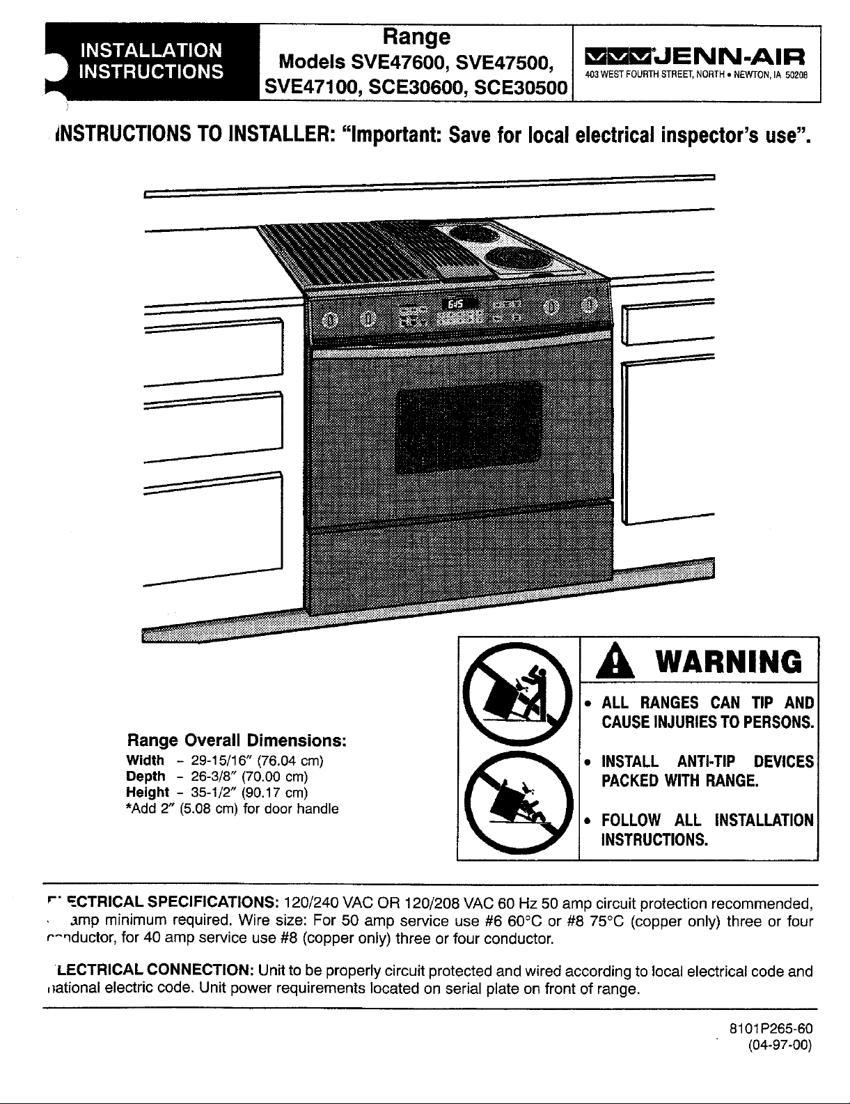
INSTALLATION
D INSTRUCTIONS
Models SVE47600, SVE47500, mmi_JENN.AIR
Range
403WESTFOURTHSTREET,NORTH• NEWTON,IA 50208
SVE47100, SCE30600, SCE30500
iNSTRUCTIONSTOINSTALLER:"Important:Saveforlocalelectricalinspector'suse".
• ALL RANGESCANTiP AND
CAUSEINJURIESTOPERSONS.
RangeOverall Dimensions:
Width - 29-15/16" (76.04 cm) _ • INSTALL ANTI-TIP DEVICES
Height - 35-1/2" (90.17cm)
•Add 2" (5.08cm)for doorhandle
Depth - 26-3/8" (70.00cm) _ PACKEDWITH RANGE.
r" =.CTRICAL SPECIFICATIONS: 120/240 VAC OR 120/208 VAC 60 Hz 50 amp circuitprotectionrecommended,
,Imp minimum required. Wire size: For 50 amp service use #6 60°(3 or #8 75°C (copper only)three or four
r^_ductor, for 40 amp service use#8 (copperonly)three orfour conductor.
LECTRICAL CONNECTION: Unitto be properlycircuitprotectedand wired accordingto localelectricalcode and
,_ationalelectriccode, Unit power requirementslocated on serial plate on front of range.
I
• FOLLOWALL INSTALLATION
INSTRUCTIONS.
WARNING
8101P265-60
(04-97-00)
Page 2
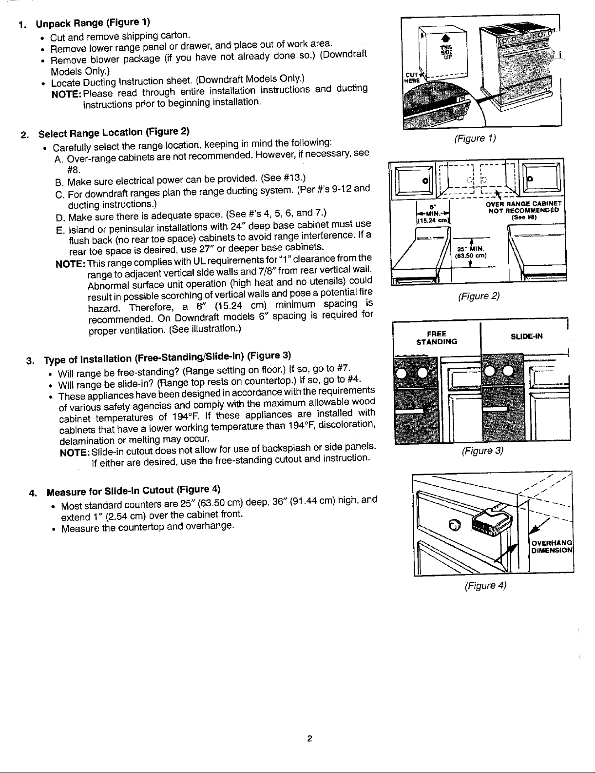
1. UnpackRange (Figure1)
• Cut and remove shippingcarton.
• Removelowerrangepanelordrawer,andplaceoutofwork area.
• Removeblower package (if you havenot alreadydone so.) (Downdraft
ModelsOnly.)
• LocateDuctingInstructionsheet.(DowndraftModelsOnly.)
NOTE:Please read through entire installation instructionsand ducting 1
instructionspriorto beginninginstallation.
2. SelectRange Location(Figure2)
• Carefullyselecttherangelocation,keepinginmindthefollowing: (Figure 1)
A. Over-rangecabinetsarenotrecommended.However,ifnecessary,see
B. Makesure electricalpowercan be provided.(See#13.) _- _ _"
C.For downdraftrangesplanthe rangeductingsystem. (Per#'s9-12and ', --"q-',_- -- '
ductinginstructions.) ._________L__.._--.
D.Makesure thereis adequatespace. (See#'s 4, 5, 6, and7.) L_'N.J OVERNoTRECOMMIENDEDRANG[=CABINET
E. islandor peninsularinstallationswith 24" deepbase cabinet must use _lscr,)1.24 (s_,)
rear toespace is desired,use 27" or deeper base cabinets.
NOTE:ThisrangecomplieswithULrequirementsfor"1"clearancefrom the _63._o¢,,)
rangeto adjacentverticalsidewallsand7/8" fromrearverticalwall. t ..
flushback (no reartoe space)cabinetstoavoid rangeinterference,lfa _, .' (
Abnormalsurfaceunitoperation(highheatand noutensils)could I,r_
resultinpossiblescorching,ofverticalwailsandposea potentialfire
hazard. Therefore, a _, (15.24 cm) minimum spacing is (Figure2)
recommended.On Downdraftmodels6" spacingis requiredfor
properventilation.(Seeillustration.)
3. Typeof Installation(Free-Standing/Slide-In)(Figure3)
• Willrangebefree-standing?(Rangesettingonfloor.)Ifso, goto #7.
• Willrangebe slide-in?(Rangetoprestsoncountertop.)If so,goto#4.
• Theseapplianceshavebeendesignedinaccordaneewiththerequirements
ofvarioussafetyagenciesandcomplywiththemaximumallowablewood
cabinet temperatures of 194°F. If these appliancesare installed with
cabinetsthathavea lowerworkingtemperaturethan194°F,discoloration,
delaminationor meltingmayoccur.
NOTE:Slide-incutoutdoesnotallowfor useofbacksplashorsidepanels.
Ifeitheraredesired,usethefree-standingcutoutand instruction. (Figure3)
• Moststandardcountersare25" (63.50cm)deep,36" (91.44cm)high,and
extend1" (2.54cm) overthecabinet front.
• Measurethe countertop andoverhange.
25" MIN.
SLIDE-IN
4. Measurefor Slide-InCutout (Figure4) _!iii
(Figure4)
Page 3
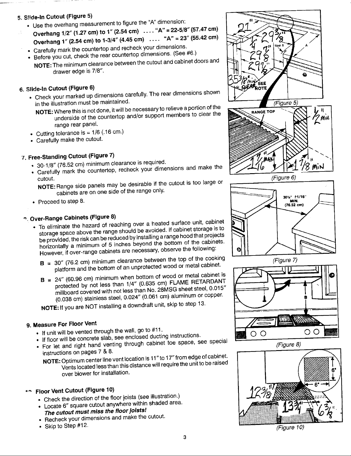
5.Slide-In Cutout (Figure5)
* Usethe overhangmeasurementtofigure the "A"dimension:
Overhang 1/2" (1.27cm) to 1" (2.54cm) .... "A" = 22-5/8"(57,47cm)
Overhang1" (2.54cm) to 1-3/4" (4.45cm) .... "A" =23" (55.42cm)
. Carefullymarkthe countertopand recheckyourdimensions.
• Beforeyou cut,checkthe rear countertopdimensions. (See#6.)
NOTE:The minimumclearancebetweenthe cutoutandcabinetdoorsand
drawer edgeis7/8".
6. Slide-In Cutout (Figure6)
• Check your markedup dimensionscarefully.The rear dimensionsshown
inthe illustrationmustbe maintained.
NOTE:Wherethis isnot done,it willbenecessaryto relieveaportionofthe (Figure5)
undersideof the countertopand/orsupport membersto clear the
rangerear panel.
• Cuttingtolerance is = 1/'6(.16 cm.)
• Carefullymakethe cutout.
7. Free-StandingCutout (Figure7)
• 30-1/'8"(76.52cm) minimumclearance is required.
• Carefully markthe countertop,recheckyour dimensions and make the
cutout.
NOTE:Range side panels may be desirable if the cutout is too large or (Figure6)
• Proceedto step 8. 3or.-_.1/le,,
_, Over-RangeCabinets (Figure8)
- Toeliminatethe hazard of reachingover a heated surface unit, cabinet _-"'T_'[
storagespaceabovethe rangeshould beavoided. Ifcabinet storageisto
beprovided,theriskcanbereducedbyinstallingarangehoodthatprojects
horizontallya minimumof 5 inches beyond the bottom of the cabinets.
However,if over-rangecabinetsare necessary,observethe following:
B = 30" (76.2cm) minimumclearance betweenthe top of the cooking
B = 24" (60,96ore) minimumwhen bottomof wood or metal cabinetis _J_______._-_. _
NOTE:
9. MeasureFor FloorVent //_/_
• If unit will beventedthrough the wall,go to #11. IF /
• Iffloor willbe concreteslab,see enclosedductinginstructions. _ O O O O
• For let and right hand venting through cabinet toe space, see special
instructionsonpages7 & 8. (Figure8)
NOTE:Optimumcenterlineventlocationis 11"to17"fromedgeofcabinet.
cabinetsare on one sideofthe rangeonly. __.,._,.-_1/_
platformand the bottomof anunprotectedwoodor metal cabinet. (Figure7)
protectedby not less than 1/4" (0.635cm) FLAME RETARDANT _)
millboardcoveredwithnotlessthan No.28MSGsheet steel, 0.015" _
(0.038cm)stainless steel,0.024" (0.061cm) aluminumor copper. _ _)" "" I _--
If
youare NOT installinga downdraftunit,skip to step 13. _ T
Ventslocatedlessthanthisdistancewill requiretheunittobe raised
overblowerfor installation.
_" FloorVent Cutout(Figure 10)
- Checkthe directionof the floorjoists (seeillustration.)
• Locate6" squarecutout anywherewithin shadedarea.
The cutout must miss the floor joists!
• Recheckyourdimensionsandmakethe cutout.
• Skipto Step#12.
3
(Figure 10)
Page 4
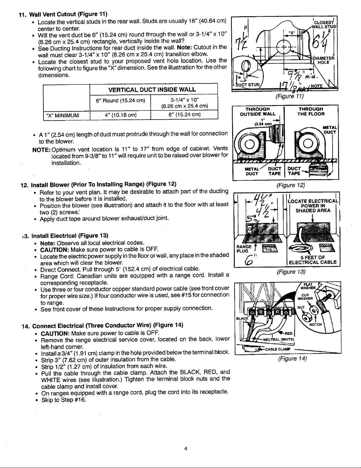
11. WallVentCutout (Figure11)
center to center. II _- _ . WALLSTUD
• Willtheventductbe6" (15.24cm) roundthroughthewallor3-1/4" x 10"
(8.26cmx 25.4cm) rectangle,verticatlyinsidethewall? /"
• See DuctingInstructionsfor rearduct insidethe wall. Note: Cutoutin the
wallmust clear3-1/4" x 10" (8.26cm x 25.4 cm)transition elbow.
• Locate the closest stud to your proposed vent hole location. Use the r_ (/_._
followingcharttofigurethe "X"dimension.Seetheillustrationforthe other
dimensions.
oceeveasuserr.uareusua0 c°si
"X"MINIMUM 4"(10.16cm) 6"(15.24cm) OUTSIDEWALL THEFLOOR
• A 1" (2.54cm)lengthofduct mustprotrudethroughthewallforconnection _- --"=""_._"D'U'_Th
tOthe blower. (_
NOTE:Optimum vent location is 11" to 17" from edge of cabinet.Vents _1_] J'J_fT
12. InstallBlower (PriorToInstallingRange) (Figure 12) (Figure 12)
,3. InstallElectrical(Figure13)
locatedfrom9-3/8"to 11"will requireunittobe raisedover blowerfor
installation. METALJOUCTDucTTAPE I DUCT_TAPE
• Refertoyourvent plan. it maybe desirableto attachpart ofthe ducting
to theblowerbeforeit isinstalled. L'IOCATEELECTRICA_'L
• Positiontheblower(seeillustration)andattachitto thefloorwithat least POWERIN
two(2)screws: SHADEDAREA I
• Applyducttapearoundblowerexhaust/ductjoint.
• Note: Observealllocalelectricalcodes.
• CAUTION:Makesure powertocable is OFF. _
• Locatetheelectricpowersupplyinthefloororwall,anyplaceinthe shaded /.-_, 5FEETOF
areawhichwillcleartheblower. _) ELECTRICALCABLE
• DirectConnect.Pullthrough5' (152.4 cm)of electricalcable.
• RangeCord:Canadianunitsareequippedwitha range cord.Installa (Figure 13)
correspondingreceptacle.
VERTICALDUCTINSIDEWALL . . .
6"Round(15.24cm) 3-1/4"x10" (Figure11)
(8.26cmx25.4cm)
THROUGH THROUGH
12.54cm
I" )_
_ / j f j _r _.-iJ / _,3rf / _ _ _ Jrf Jttf n_f IF •
I
for properwiresize.)Iffour conductorwireisused,see #15for connection / _ cup
to range, w_s,eR
• Seefrontcoveroftheseinstructionsfor propersupplyconnection.
• CAUTION:Makesurepowerto cable is OFF.
14. ConnectElectrical(Three ConductorWire)(Figure 14) __o t
• Remove the range electricalservicecover,located on the back, lower "-NEU'mAL(WHITE)
• Usethree orfourconductorcopperstandardpowercable (seefront cover __,_ w____
left-handcorner.
• Installa3/4" (1.91cm)clampintheholeprovidedbelowtheterminalblock. ,
• Strip3" (7.62cm) of outer insulationfromthe cable. (Figure 14)
• Strip1/2" (1.27cm) of insulationfromeachwire,
• Pull the cablethrough the cable clamp. Attach the BLACK, RED, and
WHITE wires (see illustration.) Tightenthe terminal block nuts and the
cableclamp andinstallcover.
• On rangesequippedwith a rangecord, plugthe cord into its receptacle.
• Skipto Step #16.
_CABLE CLAMP_
Page 5

15. ConnectElectrical(FourConductorWire) (Figure15)
• Removethe range electrical servicecover,locatedon the back, lower _ ;'_
left-handcorner.
• Removethe grounstrapscrewandbendthe strapupasshown.Installa3/4"
(1.91cm) cable clampin the hole provided,belowthe terminalblock. I,_NOl
c oo. a esure oweroa.e
• Strip3" (7.62cm)of outer insulationfrom the cable. ,GROUND
• Strip 1/2" (1,27cm)of insulationfromeach wire. WIRE
• Pullthe cablethroughthe cableclamp.
• Makealoopinthe bare groundwire andattachitto the rangewiththe screw "BASe
that heldthe ground strap, _. _'OROUNC)wlSE
• Attach the BLACK,RED,and WHITEwires (see#14.) Tightenthe terminal
blocknuts andthe cable clamp. (Figure 15)
• Tapethe groundstrapto theWHITE wire as shown.Installelectricalcover.
16. Install Options (Figure 16)
• If the backsplash or side panels are to be used, install according to
instructionsincluded inthose accessories.
17. PositionRange(Figure 17)
• Free-Standing,Adjustthe rangefeetsothe rangeandcabinetheightwill be
approximatelythe same. Slide the range into place, taking care not to --
damagefloor covering. . J'
• Slide-In. Adjust rangefeet so that range top clears countertop.Slide/lift " /
range intoplace.Adjustfeet so rangeis adjacentto countertop surface. 4 I
18, Anti-Tip DeviceInstallation (Figure16)
NOTE: A risk of range tip over exists if the appliance is not installed in
accordancewith the installationinstructionsprovided.The proper use ofthese
devicesminimizesthe risk ofTIP-OVER.In usingthesedevices the consumer
muststillobservesafetyprecautionsas statedin the USEandCAREMANUAL
andavoid usingthe oven door and/orlowerdrawer as a step stool.
Instructionsare providedfor installationin eithera wood or concretefloor.Any
othertypeofconstructionmayrequirespecialinstallationtechniquesasdeemed
necessaryto provideadequatefastening ofthe ANTI-TIPbracketto the floor.
STEP1 - LocatingThe Brackets
• Placetheunitinitsfinallocation.
• Removethe storagedrawer or lowerdoor panel(dependingon model
beinginstalled.) (Figure 17)
• Marktheflooratthe rightandleftwherethe rangefront meetsthefloor.
NOTE:Protectthe floorwith maskingtape prior to marking.
• Removethe rangefor access to the bracket mountingpositions.Use
caretoavoid damageto floor.
• Drawalineon theflooratthe backofthecutoutwhich isoffset23-5/16"
fromthe marksmade atthe front of the range(seeillustration.) _1
• Locate the center (side to side) of the cutout. See illustration for
free-standingand slide-indimensions.
• = [59.21 cm]
Positionbrackets13-7/8"fromcenterline andflushto thebackline as _1 2_5/16TYP
shownin the illustration.
• Usethe bracketto markholesfor drilling.Proceedto STEP2. _ _'F.o._0RAw_0_L'NES.AN_EAT
STEP2 - InstallingThe Brackets I
1"
,5,1
markedholepositions(anailorawlmaybeusedif adrilJisnotavailable.) F"_E-STAN0_(_6S2=,)
• Wood Construction:Drilla I/8" pilot hole in the centerof each of the SL_E-_N _01/_" [5_/_6"
Securethe ANTI-TIP brackets with the screwsprovided. Proceedto 1(75.8s_) (379__s/_S.m)_1 II
STEP3.
• Cement or Concrete Construction: Suitable screws for concrete (Figure 18)
constructioncanbeobtainedat a hardwarestore.Drillthe requiredsize
hole for the screw obtained in the center of each of the markedhole _._,-e._v_.ms
positions.SecuretheANTI-TIPbracketsto the floor, _ .._OKEr
STEP3- RangeInstallation __/_. - -
• Alignthe rangetoits designatedlocationandslideitbackintoposition.
Makesurethat therearlevelingfeet arefully insertedintoandsecured ___._"
by the ANTI-TIP brackets.NOTE: Leg levelers must be screwed out
1-1/2turns.
5
I .A-_L. (_8"2_'=.>
2g 7/8
Page 6

19. Level Range(Figure19) --IL ll
• Free-Standing.Adjustthelevelerfeettolevelrangewiththe countertop.
• Slide.ln.Adjustthelevelerfeettotakesomeoftheweightoffefthecountertop.
• Unit must be levelfor optimum bakingperformance.Check levelness inside
oven usingalevel that is placedonoven rack.
• Fornon-downdraftunitsgo to step 22.
(Figure 19)
20. Connect Blower Electrical (Downdraft Units Only) (Figure20) ,ow_,co,o
BLOWER ]lJ
• Connectthe blowerpowercordon the rangetothe blower (see illustration.) _]__ iolli i I
21. Install Flex Duct (Downdraft Units Only) (Figure21)
• Attach the flex duct to the blower and range (see illustration.) Using a
screwdriver,securelytightenduct clampat each connection. (Figure20)
22. CheckOperation (Figure22) _! _,f _k,_
• Unpackand install grill elementin one side and optional cookingcartridge in
otherside.
• Be sureto removeall packagingmaterialsfrom unit priorto applying power.
• Switchthe electricalcircuitbreakerto the ON position.
• ConsultUse & Care Manualfor operation. (Figure21)
• Checkrangetop elements.Fancomesonautomaticallywhengrillis turnedon, C.ECK .EAT pOWE,O,
•• Checkoven.C°°kingcheckventCartridgefan,doesnotenergize fan automatically. __A,,
there are noair leaks.Verifyproperairflowwith airflowcard.
• With vent fanon, check all vent duct connectionsto the outsideto makesure __"
23. Install Lower Left and Right Side Toe Plates (Figure 23) (Figure22)
• Pull protectivebackingfrom tape. ..,,, _ _.._--_ :
• Set Sideplate on floor guide plate between cabinet and range until plate is
positionedover the sidetrim. Pressplate againstsidetrim on rangeto insure
tape hasbonded.
• For Non-Downdraftunits,finish your installationby replacingthedrawer.
ROLS
24. Install AccessPanel and LowerAdjustable Panel(Figure24) (Figure23)
• After checkingfor airleaksat duct connections,installthelower rangedoor.
• Measurethedistancebetweenthelowerpanelclipandthefloor.Dimension"A".
• Cutcovemolding (providedonsome units- seeNote2)to thisDimension"A".
• Insertcovemolding (orotherselected material) into lower panelclip.
NOTE: 1) It will be easierto attachthe cove molding if the accessdoor is
removedfrom therange.
2) Tomatchyourinstallation,variouscolorsofcove moldingmaybe
purchasedfromanybuildingsupplystore, i_,._S::._ '
25. Install Jars (Downdraft Units Only) (Figure25)
• Openaccess panel. (Figure24)
• Placedrainjars intotheir holderslocatedbehindthe front legsofthe range.
NOTE:Onunits with oneside grilling,onlyone drainjar issupplied.
(Figure25)
6
Page 7

_peCial Instructi---onsFor Ven_net Toe S )ace
Additionalinstructionsfor ventingthroughthe base cabinettoe space oneithersideofthe rangewhen it isnotpossibleto vent
throughthe floor or througha rear wall.
AdditionalMaterialsRequired
1.5" Dia.x 19" long(12.7cm x 48.26cm) Flex Duct* (P/N702935) _ "
1 6" (15.24cm)90° Elbow Left 31.19" Right
• Cabinet 79.22_ Cabinet
2. HoseClamps*(P/N702331)
1 5" to3-1/4" x 10" (12.7cm to 8.26 cmx 25.4 cm)Transition* _-17.12S",-_ _-17.125"-,_
• 5._o' I (_'_ cm) (43.49_) I 5.so'
2. Wood Spacers (rightsidevent only) 1-1/2" Thick x 9" Long (3.81cm Dis-Hole| ' | Dis.Hole
X22.86cm) (,3.,7._. ._..9, or,,
*Seeyourlocaldealerorauthorizedservicecontractorfortheseaccessories. =']-.C-"-_-----"--"- '_ ---------_'---_r =
Step 1
Cut a hole in either the left or rightsideof the cabinetwall as shown in (Figure 1)
Figure1.
// -- //
!
Step2 "h J,.
shownbythe shadedareasin Figure2 or Figure3. t=7
.===.J==_
Makea cutout in the cabinetfloor of either the left or right cabinet as _r__ .---t.-
Step3 I'_'_(e=.7_m)=! _o_OT_o"N
_elocatethe mountngbracketson the blowerhousing(see Figure4.)
NOTE: The mountingbracketshown in Figure 4 are as asssembled Left Cabinet(TopView)
atthe factory for flooror rearwallventing.
(Figure2)
A. RightSide Venting ..¢ iNu='-rltd. _ 14.
2. Removebracketandreattachitwithstuds 1and2insertedinholes 11"
A and C and replaceall 3 nuts.
3. Removenutsfromstuds 5,6 and7 on air inlet side• =
4. Removebracketandreattachitwithstuds5and6insertedinholes s,owe, I- (_o=_7"-m)----'_
Dand B and replaceall 3 nuts. ,OCt'nON
(Figure3)
B. Left SideVenting RightCabinet (TopView)
1.Removenutsfromstuds1,2, 3 and 4 onmotorside. Motor Side Air Inlet Side
2. Removebracket.
4. Reattachbracketwithstuds4 and1insertedinholesA andCand
replaceall 4 nuts.
5. Removenutsfrom studs 5, 6, 7and 8 on air inlet side.
6. Removebracketandreattachitwithstuds8and5insertedinholes Mounting
Dand B and replaceall4 nuts. srecket
....
(Figure4)
BlowerAssembly
Page 8

Step4
Attachthe blowerhousingtothefloorwiththe outlettowardthedirection Right Side Left Side I
ofventing andthe inlettoward thefront of the cabinets. (SeeFigures2 Venting Venting
and 3 for specific location.) in addition,for left side venting, aspacer I
{erthemountingbracketflanges oftheblowerassembly.(SeeFigure
Step5
_,_proximately1-1/2"thick x 9" long (3.81cm x 22.86 cm)is required __
Removetheinside wire andtheoutsidestringfrom thefirst 1-1/2inches Spacer/
(3.81cm) ofoneend ofthe 5" (12.7cm)flexduct (P/N702935.)Stretch
thisend ofthe flex duct overthe end of the 5" to 3-1/4" x 10" (12.7cm (Figure5)
to 8.26 cm x 25.4 cm) transitionand secure it witha hose clamp (P/N ViewfromAir Inlet Side of Blower
702331.)
Step 6
Whenthe rangeisplacedinto position,feed the open endofthe 5" (12.7cm)flex ductthroughthe hole inthe cabinetsidewall
and throughthe sideof the range,attachitto the outletof the blowerhousingand secureit with a hose clamp (P/N 702331.)
Thetransitionshouldthenbeattachedtothe 3-1/4"x 10" (8.26cmx 25.4cm)ductinginthecabinettoespacethroughthe cabinet
floor cutout.
Step7
Installthe6" (_5.24cm)elbowto theinlet of thebtowerhousingand secureit withducttape. Theopenendofthe elbowshould
bepointedtothe left.Attachthe 6" (15.24cm)flex duct (providedwiththe range)to the elbowandto the range.Secure it with
2 hoseclamps (P/N702331.)See Step21of the installationinstructions.
NOTE:Forrightsideventing,the6" (15.24cm)diameterflexductmay becutinhalfanduseonesectioninsteadofthefull length.
"- makeit easierto assemble.
'JENN-AIR
403WESTFOURTHSTREET,NORTH• NEWTON,IA50208
Page 9

DUCTING
INSTALLATION c o M _= A N Y
I GRILL-RANGEMODELS E N N-AI R
INSTRUCTIONS 3o3_S.ADEL*ND• ,NO,_NAPOL'S,'N46226o9ol
. DROP-IN
k
FREE-STANDING
SLIDE-IN
DUCTING MUST CONFORM TO LOCAL CODE MATERIALS AND "MAKE-UP" REQUIREMENTS--
300 CFM MINIMUM
IMPORTANT: SAVE FOR LOCAL ELECTRICAL INSPECTOR'S USE
• DUCTING A JENN-AIR GRILL-RANGE IS EASY BUT CRITICAL FOR PROPER
PERFORMANCE.
• AFTER READING THESE INSTRUCTIONS PLAN THE DUCT RUN.
• USE THE 'DUCT LENGTH CHART' TO FIND THE EQUIVALENT LENGTH OF THE RUN.
• SHIFTTHE BLOWER TO 'HIGH RANGE' IF INDICATED (DONE BY SNAPPING THE
'RESTRICTER RING' OUT OF THE BLOWER INLET), BE SURE BLOWER IS
NOT RUNNING.
• INSTALL THE DUCT HARDWARE.
• ENJOY GRILLING AND COOKING AT ITS FINEST!
THIS UNIT IS RATED AT 60 FEET OF STRAIGHT DUCT
LOW RANGE IS UP TO 30 FEET--HIGH RANGE IS 31 TO 60 FEE'[
IMPORTANT
GENERAL CONSIDERATIONS:
1. Use 6" diameter round or 37/4"x 10"rectangularonly, 5.The numberofdownstreamelbowsortransitionsshould
except as follows: For Electric Models, 5" diameter belimitedtothree.Theinitial5"to6"straighttransition,if
roundMay beusedfor ventingstraightout the backof used,neednot becountedinthis number.
therangeanddirectlythroughthewallfor10feetor less.
For Gas Models with Electric Ovens, 5" diameter 6. Handmadecrimpsarelikelyto causerestrictions.
roundMust be usedif the ductlengthis10feetor less.
7. Ifan alternatewall or roof cap is used,be certain duct
2. Donotuse 5"elbowsexceptin a5"system.Instead,use sizeisnotreduced,andthatthereisabackdraftdamper.
a5"to6"transitionfollowedbya6"elbow,ora5"to31/4,, It is best to use listed caps to be certain of proper
x10"elbowtransition, performance.
3. Usequalitymetalductofat least26gaugegalvanizedor 8. Thermalbreaks:Inareasofextremecoldweather,it may
24gaugealuminum.Inferiorqualitypipeandfittingscan be necessaryto provide a short length of nonmetallic
cause up to twice the restrictionshown and is a poor ductas closetothe wallaspossible,to preventconduc-
value. See box on page4 for optionalunder-slabduct- tJonalongthemetaJduct.
ing.Local codesmay require a heaviergauge material
orrestrictPVC. 9. High altitude installations: It is advisable to reduce
allowableductrun by20%.
4. Distancebetweenadjacentfittings (elbows,transitions,
etc.)shouldbe atleast18".Thefartherthebetter.Closer 10. Followthe duct calculationon page 2 carefullyfor best
distancepromotesturbulencewhichreducesairflow, performanceandsatisfaction.
1 PART NO. 204754D
Page 10

PLAN THE DUCT RUN
1. Make a sketch of the total system. Identify the type of each fitting and the length of straight pipe.
2. Enter your run into the 'Duct Length Chart' in the next section.
ExampleI Example2
__ _.5"to 6"Transition to6" Transition
2' of 6" ound
Elbow
2' of6" Round
\ 6"Elbow
' \ 4' of6" Round )_"
. 6 of6 Round
.6' Elbow 6" Round
6"Elbow ;"Elbow
4' of 6" Round
6"WallCap
10'of3¼"x 10"Straig C,..,.
31/4" X10"Transition
DUCT LENGTH CHART
1. Elbows, wall caps and other fittings are shown in the table on page 3 with their equivalent straight duct
length. Each fitting value must be added to the amount of straight duct length used, to determine the
overal! straight duct equivalent length.
2. Using the examples above:
ExampleI Example2
DuctFitting No.ofFittings TotalEquivalent DuctFitting No.ofFittings TotalEquivalent
Equivalent Length-Fittings Equivalent Length-Fittings
Length Length
5"to6"Transition 1 1 1 5"to6"Transition 1 1 1
6"Straight "f 2+4+6= 12 12 6"Straight t 2+4+6+4= 16 "t6
6"Elbow 5 2 10 6"Elbow 5 3 15
6"WallCap 0 1 0 6"to31/:_' x10"
Total 23 31/4,x10,Straight 1 10 10
Transition 1 1 1
31/4"x10"WallCap 0 1 0
Total 43
INSTALLTHE DUCT HARDWARE
1. Using good quality ducting material, install per these instructions. Follow the General Considerations
page 1, Do's and Don'ts box on page 4, and Grill-Range Installation Instructions. A few minutes an£1
pennies spent now will pay long term dividends for the life of the range.
2
Page 11

USE TABLE BELOW TO CALCULATE TOTAL SYSTEM
DUCT FITTING EQUIVALENT LENGTH NO. OF FITTINGS LENGTH-FITTING
6" Dia. 90 ° Elbow 5 FL (1.52 m)
6" Dia. 45 ° Elbow 2.5 Ft. (.76 m)
5" to 6" Transilion .._
P/N A456 _mn.owTHZS
o27c=to_24cm} _ _ 1.0 Ft. (,30 rn)
6" tO3%" x 10 " 90_ Elbow
(1524 c rn tO 8 25 cm X 254 cm)
WN A496 5 Ft. (1.52 m)
3%"X 10 " to 6" 90" ELBOW
{826-cm • 254 cm to 1524 Crn)
P/N A496 9 Ft. (2.75 m)
6" to 3V,'*x 10" Ttansitton _._"_
(1524 Ctn to 826 cm x 254 cm}
P/N A463 1 Ft. (.30 m)
(Also PiN A453 _nS_de O_¢t) AIR F'LOW
3%"x 10" to 6" TransilJ_l ../_
(82Scmx254cmto15.24cm)
WN A463 4.5 Ft. (1.37 m)
5" to 3%"x 10" 90° E_¢ N /_.,_
[12,7 cm to 8,26 cm X 25.4 cm)
P/N A4g5 AmRow T,_s 6 Ft. (1.83 m)
3,1,"x 10" 90° Elbow
omECT_0N_OT
RECOI_Eta_tD AIRFLQW
AIR F1-OW
AIR FLOW
AIR FLOW
DIREC*_ NOT
REOOMI4EN[_ AERF].O_
DUCT F|TTING TOTAL EQUIVALENT
is.2s¢,_x_.4 cm) _ 5 Ft. (1.52 m)
3%"X 10" Flat Elbow
[8:26cmx2s4cml _ 12Ft.
6" Wall Cap 5" Wall Cap m,_
(15.24 crn) (12.7 ¢m)
P/NA406 PIN A405 0 Ft. (0 m)
3%"• 10" Wall Cap
_s26cmx2s.4cm_
WN A4D3 0 Ft. (0 m)
10" • 10" Roof ,lack
USE LEIGHPRODUCTS 0 Ft. ((] m)
P/N 5850
(Z5 4 °q x 25'4 cm_
IAblO mmt4Hle R J_nn-AIr p/N ?01943)
5" P/N 708786
6" P/N 715557 2 Ft. (.61 m)
THERMALBREAK
6" DIAMETER (For flex duct,
STRAIGHTDUCT- FEET multiplyby 2) 1 Ft. 1.30 rn)
3V,"x10"
STRAIGHTDUCT. FEET 1 Ft. (.30 m)
(Short Run)
(3.66 rn)
SYSTEMTOTAL
1.Thisgrill-rangeisequippedwith adualrangeblower.Itis shippedfromthefactory
SHIFTINGinLOW THE BLOWER FROM 'LOW RANGE' TO 'HIGH RANGE' _
RANGEformostinstallations.IftheEquivalentDuct Lengthexceeds
30 feet it must beshifted to HIGH RANGE. Do not shift to high rangefor _ J_,,,'11
1.BLOWER
OFF
affecttheflamepatternongas units.
In theexamplesonthe precedingpage,the blowerin example#1 shouldbe
installed as received from the factory.The blower jnexample #2 should beshiffed_ighRange, ,_
.o shift to HIGH RANGE,be sure blower is stopped and carefully remove
thespring loaded"RESTRICTERRING'out of the blower inlet.Seeillustration
at fight.
shorter lengths.Thiswill causeexcessivenoise,conditionedair loss and _ 2. SNAPOUT RESTRICTERRING
3
Page 12

' s"ola.su=t TYPICALDUCT ARRANGEMENTS
Typical througft
Rein" DUCt
(Outside Waft)
(|l_.side Wall) (See special instructions
Through Cabinet Toe Space
204917)
OPTIONAL DUCT ARRANGEMENT UNDER CONCRETE SLAB
NOTE; PVC sewer pipe Wpe PSM 12454-S
Also Required: Jenn-AW Kit P/N 712139,
Ilvaileble trom your authorized set-
t
Sewer Pipe
Coupling
Sewer Pipe Elbow Sewer Pipe Elbow
Pack tightly with
gravel or =rand
completely around pipe, I
Note: Window WeB installation Wall Cup - Sewer Pipe
for electric models only.
12" Min, _ * Cut Off Pipe at
!
Sell the space between outside of gravel or sand
wall ¢mp inlet and inside of PYC 6" Dla. PVC completely around pipe.
couf_kl g wit_ ¢au_blg m_te_L Couplleg
use 5" 112.7 cm), 6" (15,24 cm), Use 4" (1016 ore) dryer vent pipe
or 3_/," x 10" (8,255 cm x 254 cm), or flex duct,*
piPe as recommended for your !
Use rec<;mmende_Wallcap_ Use launary type wallCap.
model. _ (_
UsenomomthanOneg0°e_owwim Over run your systenn with too
fiveinch (1P.7 ore)duct _r thr_._g0* marly b_rtd$aridtu_$.
eLb0wswilhsixinch(15.2cm)or3"x10" Pad 708786
(8255 crn x25 4 ore) _u_ Fits 5" (t 2.7 cm) Round MODEL ._.d$
Dum systemto the 0uts,:le and conc_lled spaceofa building. PART _15557 MOD_tL
Mix 6" (15.24¢m)duct ar',d3'/," x10" Reclucebackto 5" {12 7 cm) system Duct. Adds 2 ft. to duct Duct, Requires6%" (15.875
duct (8.255 cm x 25A cm) within the atterusieg 6" (15.24cm)or 3V,"x 1G*' length calculation cm) 0ia. opening,
samesystem rf necessary (8.255 cm x 25.4 cmt.
Tape all joints securely witi_ Butt joints, atwaysuse male-female _ f_
severalwrapsof fade. Connectiorl$_ndirectronof flow.
0se one unit per duct system. Exhaust mote than one unit into a
"Althougrtriot recommended,5" Or 6'* metal flex duct maybe LISe_.Due to Single-darrtper, down P/N 5950
_eltregu/arsutfac_°tf_exib_e_'uct_'_'eacrtfc_off!exduCtc°unfaastw°l_l diScftargetofit3%'xlO" RoofJacktO'xt(_"
feet of regular metal _uct. Also, eachelbow made inflex _luctwc_JIdcount {E.25_cm x 25.4 cm) duct. (254 crnx 254 cm)
twice as muct_ as standard metatel_ow. The 0est idea withftexibleducting
istOkeePitasellorl and as _t_'_ightas _ossi_e.
oo oo.'r WALLCAPS/THERMALBREAKS
Vecltintoartatticor ¢r_wlspace,walls cm) Dia opening.
sJn21esyst(_n
Pack tightly "t_th
Duct. Acids 2 ft. to duct Pits 5" (127 cm) Round
length CalCulation. Duct. R_uire_ 5%" (13.34
PitsS"(15._ ore)Round Fits 6" t15.24 cm) Round
MODEL A44_ LEIGH PRODUCTS
Sewer Pipe Elbow
4 PARTNO. 204754D
 Loading...