Page 1
m JENN.AIR
Use & Care Manual
Frost Fr ee Re frig e r at ors
MODELS JRT1960, JRT2160 , JRTD229,
JRT199, JRT219, JRTF1960 , JRTF2160
I
Model JRTD229
P r i n t e d i n U .S .A. Pa r tN o . _ 7 0 3 0 4- 1 Ca t. N o . S T U 1 96 0U A
1 996J e nn-Air 1 / g6
Page 2
Your Jenn-Air frost-fre e ref r igerator w as designed , engineered, and manufac-
tured to the highest standards of quality and performance. Since this manual
explains how you can obtain the best use of your Jenn-Air , it is essenti a l th a t
you follow the instructions carefully.
Should you have any questions about using your Jenn-Air appliance, write to
us. Be sure to provide the model number of your appliance. Jenn- A ir Custome r
A ssis t a nc e , c /o Ma y t a g C us t om er S e r v i ce , PO B o x 2370, Clev e l a n d , T N
37320-2370.
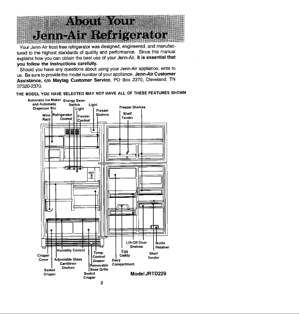
THE MODEL YOU NAVE SELECTED MAY NOT HAVE ALL OF THESE FEATURES SHOWN
Au to ma t ic Ice M _ ker Energy Sav e r
and Automatic Switch Light
Dispenser Bin
RVi i n k R ef ri gern t tr°;
Crisper Caddy
Cover Adjustable Glass D rawer Dai ry Tender
Sealed
C rispe r Sealed Model JRTD229
Crisp e r
Egg
Compartment
2
Page 3
1 . Use the three-pronged plug only with a grounding receptac l e to p r ovide prot e ction
from electrical shock. This appliance must be install e d in accordance with the
installation and grounding instructions on pag e 4-5.
2 . Unplug your r e frigerator before cleaning condenser , replacing a light bulb, or
m a king any repairs. Any servicing shou L d be performed by a qua l ifi e d technician.
3. L n case of pow e r failure, minimize door openings. If power failure is of long duration,
prote ct froz e n food by placing bl o ck s of dry i ce on t o p of th e p ac k a g e s, o r c h ec k with
a lo ca l fr o z e n f o od s l oc k e r pl a nt about temporary storage . Frozen foods which have
thawed completely should not be refrozen .
4. Any e lectric service cord that becomes frayed or damaged should be imm e diately
repaired or replaced. Never unp l ug your app l iance by pulling o n th e po we r c ord.
5. Your refrigerator shou l d not be operated in the pres e nce of explosive fumes .
6. Remove the doors from any out-of-use refrigerator to prevent child entrapment and
suffocation.
7. DO not pl ac e fing e r s or h ands on the automatic ice making mechanism whi l e th e
refrigerator is p l ugged in. This will help protect you from possible L njury. L t wil l also
prevent interference with moving parts of th e ejector mechanism and the heating
element that releases the cub e s.
Page 4
If you are installing your new refrigerator yourself, please follow these helpful sugges-
tions .
1. Remove ba s e skids, i I- J ] L [- j I
2. Remove all exterior and int e rior tape carefully and ,, ,_ll
retain old tape. Make a small pad of this tape to pick
o ff a n y rema ini n g t a p e re s id ues. This w ill eli m i na t e t h e
need to use dangerous S olvents of any kind.
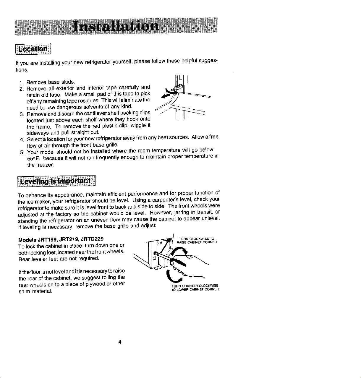
3. Remove and discard the cantilev e r shelf packing clips
located just above each shelf where they hook o nto
the frame. To remove the red plastic clip, wiggle it
sideways and pull straight out.
4. Select a lo c ation for your new refrigerator away from any heat source s . Allow a free
flow of air through the front base grille.
5. Your model should not be inst a lled where the room temperature will go below
55° , = . b ec aus e Jt will not run fr e q u e ntly e noug h to mai n tai n pr o p er te m p era tu re i n
the freezer.
T o enhance its appearance, maintain effici e nt performance and for prop e r function of
the ic e maker, your refrigerator should be level. Using a carpenter ' s level, ch e ck your
refrigerator to make sure it is level front to back and side to side. The front wheels were
adjusted at the factory so the cabinet would be level. However, jarring in transit, o r
standing the refrig e rator on an uneven floor may cause the cabinet to appear unlevel.
If lev e ling is nec e ssary, remove the base grill e and adjust:
Models JRT199 , JRT219, JRTD22 9 T Ua N C L OCK W ISE TO
T O lo c k t h e ca binet i n p la ce , t u rn d o w n o n e or I . _.
both locking feet, located near the front wheels.
r-,
Rear leveler feet are not required .
if the f l oor i s n o t leve l a nd i t i s nec e ssary to r ai se xt_
the rear of the cabin e t, we suggest rolling the
rear whe e ls on to a piece of plywood or other
shim mat e rial , T o L OWER CA BI NE T C OR NER
RAISE CA B INET C O R N ER
T URN COUNTER - CLOCKWI S E
Page 5
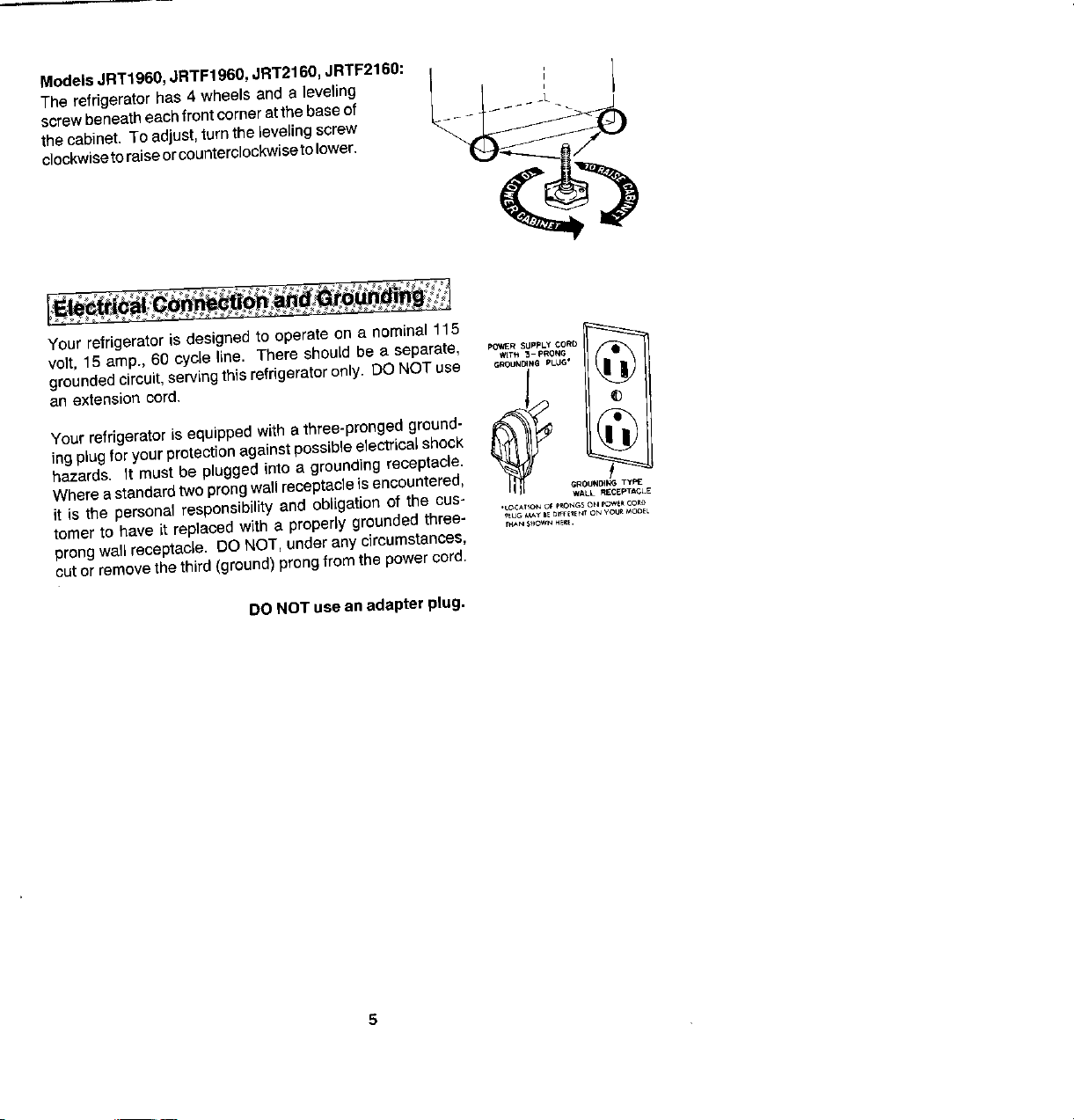
Models JRT1960, JRTF1960, JRT2160 , JRTF2160: i _ I
T he refrige r at o r has 4 w h ee ls a nd a l e v e ling I I , I
the cabinet. To adjust, turn the l e veling screw
clockwise to raise or counterclockwise to lower.
s c r ew b e neath e a c h front co rn e r a t th e base o f _- _ _L
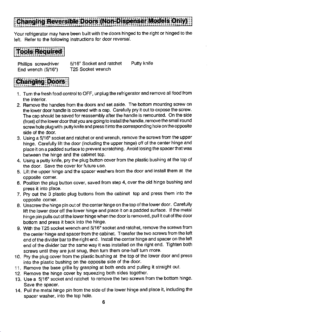
Your re f rigerator is de s i g ned to operate o n a nomina l 115 _
volt, 1 5 amp ., 60 cycle line . T h er e should be a s e parate, . _t. _-P. o .G •
groun de d c ir c uit, se rving this r e frig e r a t or o nly, DO N O T us e _ o ,_,_ p_.
p Q _ VE R S UppLy CORO
ing plug for your prot ec t ion against p o ssibl e e lectri ca l s ho c k
h a z ar ds . I t mu s t b e plugged into a ground i ng rec e p t acle.
Where a standard t wo prong w aft receptacle i s encountered, _u.D , _ T_
Your refrigerator is equipped with a three-pronged ground-
it is the persona l responsibility and obligation o f the cue- WA L L .E C E.' . CLE
tomer to have it replaced with a properly ground e d three- , ,o_,_,_o . ,E,_ o_oo,_oo_
• L O C A TIQ N O_ p_N G $ OH p Q V # _ _O R O
T H_,N S_ WN H E_t .
prong w all r e c e pta c Je. D O NOT, und e r any ci r c umst ance s ,
cut or remove the third (ground) prong from th e power c o rd .
DO N O T use an adapter p l ug,
Page 6
Your r e frigerator may have been built with the doors hinged to the right or hinged to the
l e ft . R e fer to the following instructions for door rev e rsal.
Phillips screwdriver 5 / 16'r Socket and ratch e t Putty knife
End wr e nch (5 / 16") T25 Socket wrench
1. Turn the fresh food control to OFF , u np l ug the refrigerator end remove all food from
the interior.
2. Remov e the handl e s from the doors and set asid e . The bottom mounting screw on
the low e r door handl e i s covered with a c ap. Carefully pry it out to expose the screw.
The cap should be saved for reassembly after the handle is remounted. On the side
(front) of the lower door that you are going to install the handle, remove the small round
screw hole plug with putty knife and press it into the corresponding hole on the opposite
side of the door.
3. Using a 5 / 16" socket and ratch e t or end wrench, remove the screws from the upp e r
hinge. Carefully lift the door (including the upper hinge) off of the center hinge and
place it on a padded surface to prevent scratching. Avoid losing the spacer that was
b e tween the hinge and the cabinet top.
4. Using a putty knife, pry the plug button cov e r from the plastic bushing at the top of
the door . Sav e the cover for future use.
5. Lift th e upper hinge and the spac e r wash e rs from the door and install them at the
opposit e corner.
6. Position the plug button cover , saved from step 4 , ov e r the old hinge bushing and
press it into place.
7. Pry out the 3 plastic plug buttons from the cabin e t top and pr e ss them into the
opposit e corner .
8 . Unscrew the hinge pin out of th e center hing e on the top of the lower door. Carefully
lift the lower door off the lower hinge and place it on a padded surface . If the metal
hinge pin pulls out of the lower hinge when the door is removed, pull it out of the door
bottom and press it back into the hinge .
9. With the T25 socket wrench and 5 / 16" socket and ratchet, remov e the s c rews from
the center hinge and spacer from the cabinet. Transfer the two screws from th e left
e nd of the divider bar to the right end. Install the center hinge and spacer on the left
end of the divider bar the same way it was installed on the right end. Tighten both
screws until they are just snug, then turn them one-half turn more.
10. Pry the plug cover from the plastic bushing at th e top of the lower door and press
into the plastic bushing on the opposite side of the door.
11. Remove the base grille by grasping at both e nds and pulling it straight out.
12. Remove the hinge cover by squeezing both sides together.
13. Use a 5 / 16" socket and ratchet to remove the two screws from the bottom hinge.
Save the spacer .
14. Pull the metal hinge pin from the side of the lower hinge and place it , including the
spacer washer, into the top hole.
6
Page 7
15. P r y out the t w o screw hol e plug buttons on the bottom left side of the top door and
lower door. On some models , remov e the door stops (metal plates) on the bottom
of e ach door and install them on opposite sides. Press in the plug buttons in the holes
on the right side of both doors.
16. Set thelower door on the bottom hinge, making sure the hinge pin entersthe b ushing
in the door bottom.
1 7 . Wh i le h o Wtirtcj the do e r in a c le sed pos i t len, ta ke t he c a nter hinge pin that w a s
re m ov e d in s tep 8 a nd scr e w it through the l e ft ho l e of the ce nter hinge and into th e
bottom d o or bushing. Make sure the long pin goes into the bottom door and the sh o rt
pin goes into the top door.
18. Set the upp e r door on the center hing e , making sure the hinge p in e nters the door
bu s hing. W h en you close t h e door, the gas k e t s h ould h old it in p la ce.
19. Making sure to use th e same number of spa c ers th a t were originall y used ben e ath
th e upp e r hing e , i n stall the hing e mount i ng s c r ews . Bef o r e tigbt e ningthese sc r ew s,
make sure the top of the door is level with the cabinet to p, and the s p ac e b e t w e e n
the d o or is equidistant acros s the entir e front. Avoid over-tightening these screws.
Tighten both unti l they ar e just s nug, the n turn them in another one-half turn.
20. Ex a mine the door ga s ket all around e ach door, making s ure no gaps are visibl e
b etweenthegasketandcabinet. Ifag a ps h ows, try s t re t chingtheg a ske ta way#om
the d o or . The mag n et will c ontact the cabin e t surface.
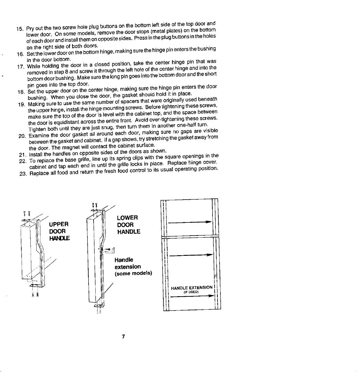
21 . Ins t a } ] the handles on op posit e sides of the doors as sh o w n .
22. To re p lace the base grille, line u p its sp rin g clips with the s q uare openin g s in the
cabin e t and tap each end in until the grille lock s in pl a ce. Re pl ace hing e cover.
23. Re p la c e all food a n d return the fresh food control to its usual operati n g position.
17 j ./ " I
_ J _ 7 LOWER
..... UPPER DOOR =
DOOR HANDLE II
_ J
n
Handle
. I extension
. _,_ / (some models)
/
I HANDLE EXTENSION I
[IF U SE D )
Page 8
I
Your ne w refrigerator has two cont r o l s. One for 9 is coldes t I " $ " I
regulating the temperature in the fresh food com-
par t ment and one for the fr ee zer. The fresh food
compartment and the freezer compartment con - Saves / _. Reduces Exterior
trois a re lo c at e d at th e to p front of the f r e sh food
En e r gy \ / Moisture
compartment. Turn both contro l s to "No. 5" to start U
your refrigerator.
m
I
The"No.9"freezercontrolsettingisrecommended _ 9 i s cold e st
for short t e rm use only.
Your refrigerator may run for several hours when you fi rst start it. This is normal and
shouldn't be cause for alarm.
TO start " Se t fr e sh food coctrol on "5 _
Set frse z er contmt on ' ¢ J"
C hanging either control wi ll have some T um_esh_ , _ to _e_
effect on th e temperature of the other com- Refrigerat°rtc * ° WARM: h _ lherrtu mbe_
partment . Re fngerator too COI O: Tum fr e sh f°°d c°nt(°t t° l _e : c
/ower numb _.
Turn fr e ezer con _- ol to next
t n a day or two, you may d ecide that on e or F _ z er _ WARM: h l ghernumbe K
both compartm e nts s h ould be colder or Ft e e z er _ oOOLD Tur n# e e zeroontro/tonext
warmer. If so, adjust the control(s) as
_ wer numb e r
instructed i n the accompanying chart. Refng erat e rOFF Setfr e shf°°dr _ °ntroltoOFF .
I MP ORT A NT : Except when starting, do not chang e either c ontro l more than one numb e r
at a tim e . A l low 24 hours for temperature to stab i lize b e fore resetting.
At times, the front surfac e s of your refrigerator cabinet may b e warm to the touch. This
is a normal function of your refrigerator. This feature prevents moisture from condensing
on the outside of your refrigerator during humid weath e r. This condition may be
noticeable when you first start your refrigerator, during hot weath e r, and during
excessiv e or lengthy door openings.
Page 9
T he Energy Saver switch c ontrols a he a t e r designed to prevent moisture aco u mulation
between the refrigerator and freez e r door frame. During humid weather , moisture
coll e cts on objects that are cooler than the surrounding air. This condensation can be
eliminated by applying a small amount of h e at to the su rf ace upon which the water
a c c umulates .
When the Energy Saver switch is on "Saves Energy" , no heat is applied to the surface.
It is saving both energy and money. If humidity increases and condensation appears,
turn the Energy Sav e r swit o h to "Reduc e s Exterior Moisture". Be sure to turn the Energy
Saver switch back to "Saves Energy" as the humidity drops to save energy.
In areas of relative l y high humidity , the Energy Sav e r Sw i tch in the " Reduces
Ext e rior Moisture " position will minimize any coll e ction o f moisture o n th e outside
sur f a c e of th e cabin e t .
For efficien t energy use:
1 . B e sur e t he r e fr ig er at or is level an d ven t il at ion around the fron t g ri lle i s not b locked,
2. C h e c k door s e als occasion a l ly f or l e a ka ge , Ch e ck at various pl a c e s, top, b ottom,
a nd sid e s .
3 , Ch e ck th e t e mperatur e ; avo id unn e c e ssar y cold set t ings .
4, K ee p t h e fr e eze r n e ar f ull capa city ; l e ss c old ai r is lo st dur ing d o or ope n i n g s .
5. L e t h o t di s h e s c o o l b e for e p u tt in g i n t o ref r i g e r a t o r o r fr ee z e r ,
6, C o v er liqu i ds; i f unco ve red, th e un i t mu s t w ork l o n g e r.
7, C lean refrigerator c ondenser co i ls a t least tw i c e a y e a r.
Page 10
To maintain the natural flavor, moisture , and nutrition of fr e sh foods, we recomm e nd
that all dishes , trays, and containers of food be covered .
tioned to suit your sp e cial needs. To remov e
a shelf, lift the rear straight up a fraction of an
inch and pull straight out. To lock into anoth e r
position, tilt the shelf with the front up. Insert
hooks into desir e d frame openings and let the
Adjustable cantil e ver shelves can be posi- _li_ll 1
shelf settle into plac e . Make sure it
is securely lock e d at the rear.
The Temp Control Drawer, between the top and second shelves, provides short term
storage of fresh meats without freezing. This drawer will provide extra chilling only if the
cantilever shelf that supports the Temp Control Drawer is in the 2nd, 3rd, or 4th shelf
adjusting posit i ons. Keep the draw e r tightly closed at all times .
Th e s liding lever on th e b ack w a l l , a b ov e th e dr a wer ena b l e s you to var y the int e rnal
t e mp e ra tur e s i n side th e d r a w e r. With t h e leve r s e t at t h e "C old " po s ition, th e t e m peratur e
in s id e t h e d r awer wil l b e cool e r and you ca n sto r e most good qu a lity m e ats s e v e ral day s .
A ll m e ats or poult ry shoul d b e stored in th e ir original s tor e w r appings or in pla s tic b a g s
to r e duc e t h e e vaporation o f moi s ture f rom t h e m .
To r e mov e t h e T e m p C ontrol Dr aw e r, pu ll it out un t i l it s to ps . Th e n apply a l itt le m or e
p r e s su r e a n d pull compl e t e ly out.
To use your wine rack fit it along
e i ther s i de of any ref r igera t or III ,, ,/ "
shelf and lay the wine bottle on
the rack.
10
Page 11
The Sealed Crispers are ideal for storing vegetables and fruit. Keep your crispers tightly
closed to insure fr e shness. Storing l e afy vegetables, such as c e lery and lettuce in plastic
bags, reduces moistur e evaporation.
The crisp e rs slide out for e asy ac c ess to foods stored within. They are complete l y
remov a ble for c lea ning (hand w as h on t y) or for us e el se w here fn your kit c h e n,
Th e crisp e r cov er a ls o serv e s a s a r efrig era tor stor a g e sh e lf. T o r em o v e f o r cle a ning,
push up on th e glass cover from und e rneath and c arefully remove.
The humidity control levers are located on the shelf above the crisper drawers. Th e slide
control shou l d generally be set at the "Low" setting for fruits and the "High" setting for
vegetables.
Occasionally, you m a y notice water droplets on the back wall . This i s normal.
De f rost wat e r is used to maintain humidity l e vel and helps keep food fresh longer.
Excess water drains into the d efrost pan beneath the cabinet an d evaporates.
11
Page 12
Yo u r model ha s an egg c a dd y t hat fits s ecure l y on a door s h e lf. T h i s e g g caddy c an b e
removed and carried to your working a r e a.
Door gask e ts are magn e tized to insure an air tight seal all around, T hese gaskets cling
to the cabinet front, once the doors are closed to within their magn e tic rang e .
position on the door. Lift the shelf straight up unti l i t clear s
the retainer s on th e door liner and pull s traight out. Rev e rse
u o. oosve as t eo oer
this procedure when replacing a shelf.
Some models have a bottle retainer located on the lower refri g erator door s helf. It
pr e vents tall bottles from falling out wh e n the door is opened or closed. Th e bottle retain e r
can be adjusted to any position on the shelf by sliding sideways .
All models h ave a S h elf Tender lo c ated on on e of th e refr i g e r a tor do o r s he l v e s . It
provides upright storag e for pa c kages or bottles. The Shelf Tender can be a d j ust e d to
any position on the shelf by sliding sideways.
12
Page 13
To maintain the natural flavor, moistu re, and nutrition of frozen foods, and to prevent
fr eez er bu rn , we r ec o m m en d that a ll f oo d s be w rapp ed o r sea led p ro p e rly.
end up appro x imately 1 / 4" (2) push the s helf to the right
a s far as it w i l l go into the socket s (3) lift t h e left end up T
a p pro xi matel y 3 " a nd (4) p ull the r i ght end b a r s out of t he _ FREE Z ER S HEL F
soc k e t i n t he si de wa ll .
Some model s h av e a n e x p a n dable-width freezer she l f " _-_ _
w hich adj u sts sidew a ys t o open up a f u ll-he i gh t space ] _ li
for tall pa c kages, such as pizza. The right side of the _ _ ]l
shelf i s supported by a wide leg that slides s ideways in ._
ch a n n e ls on th e unders i d e of t h e s h elf. The s heff ca n __
also adjust to two heights. This r e quire s removing the g //////I/ I I Il\\\\\\\\\_\_;.; ; _ ----------------- _J_-. , _
shelf from the freezer , sliding the leg o ut of th e channels,
r e -inserting it in the alternate height position and return-
ing the shelf to t he fre ez er, hangi n g on th e a lt e r n ativ e
pa n ded f u lly t o t h e right w all surfa c e, unless vert i cal
storage of narrow packag e s is desired.)
hooks ( usua"Y ' the dght supp°rt se=i°n w " ' be ex " L 11 f-
S o me models h ave a til t o ut b a ske t on th e l o wer s helf of __ .P) Ill [
the fr e e zer d o or. T i l tin g th e b a sk e t for w ard by it s u pp e r
edg e prov i de s ea s y acce s s to packages, A slight push
upward will tilt the basket back to its prop e r stored
posit i o n.
1 3
Page 14
Y our refrigerator come s equip p ed w ith i ce cube tray s and a stora ge bin (on most
mod e ls.) T o r e l e ase froz e n c u b e s , h old t he trays u p side down and twist both ends.
Some models are designed so an Automatic ( oe Maker can be easi l y install e d whenever
you want it. Order the ice maker kit number shown on the label on the cabinet back . The
kit contains installation instructions, water connection instructions and other information
concerning the ice maker operation.
The water inlet tubing assembly requir e d to complete the water connection to the water
v a lv e i s locat e d in th e c risp e r dr awe r i n a b a g. C onn ec t th e i ce ma k e r t o t he wa t e r supply
as instructed in the s e parate L nstructions, furnish e d with the refrigerator.
Th e a utomati c i ce mak e r is d e signed t o f u rnish a continual s u pp l y of i c e cub e s. T h e
amount of ice produced depends on the temp e rature in the fr e e z er s e ction of your
refrigerator. T he colder the fr e e z er section, the more ice is produced. We suggest you
start with your refrigerator and freezer controls at their mid settings. In most cases , this
is satisfactory . If the door to the refrigerato r or fr eez er is o pen e d frequently o r
temp e ratur e s in the kitchen ar e abnormally high, a cold e r setting may be necessary.
Aft er y ou r mod e l h as b een i n st a l le d an d th e wa t er sup ply c o nn e c t e d t o t he i ce m a k e r ,
it may take 8 to 12 hours before th e ice maker furnishes any usable ice cubes . The first
one or two harvests will probably contain undersized and irregular cubes because of
air in the supp l y line. Th e init i al harv e st may al so contain imp u r i ti e s from the n e w w at e r
supply piping. Therefore , all cubes from the first two or three ha rv ests should be
discarded.
Und e r certain rar e circumstan c es , ice cubes may be discolor e d , usually appeari n g with
a green-bluish hue. The cause of this unusual discoloration is apparently a combination
of factors su c h as certain characteristics of local wat e rs , household plumbing and the
a ccu m u lati o n o f co pp e r s a lts i n an i nac tiv e wa t er s u pply l in e whi ch fe e ds th e ice m a k er .
Continued consumption of such discolored ice cubes may be harmful to health. If such
discoloration is obs e rved, discard the ice cubes and contact the dealer from whom the
ice maker or refdgerator was purchased.
Ice cubes that have been in the ice storage for a considerable length of time may pick
up oft-flavor taste, stick together, and gradually become smaller . We suggest that these
cu b e s b e thro w n aw ay. We a lso s u ggest u sing a n o pen b o x o f b a ki n g s o da in th e
refrigerator for food odor absorption.
Ce rt a in s ou nds may a cc o m pany th e var i o u s c y cle s o f th e i ce ma k er . E xa m pl e s ar e : (1)
the motor may have a slight hum, (2) the cubes will rattle as they fall into an empty storage
bin, and (3) the water valve may click or "buzz" occasionally. All of these sounds are
normal and shou l d be ignored.
14
Page 15
N o t e: Wh e n disp e nsing i c e c ub e s , it is imp o r tan t that y o u us e o nl y the i ce supplied by
thisicernaker . I ce from anyoth e rsourceoouldcauseanicejam. Ifthis happens, r e mov e
and discard all ice from the storage bin and any ic e lodged in th e ic e chute.
AUTOMATI C
IC E MAKER
Your au tomat ic ic e m aker is located n e ar t h e / SENSOR
t o p o f th e fr e e ze r co mp a rtm en t b eh in d th e I ce AR M
Access Panel. To gain access to the ice p / _
T h e i ce mak e r ha s a w ir e s e n s o r arm th a t i s
making mechanism, lift the Ic e Access Panel. _ OF F
conn e cted t o a shut-off switch. This arm stops
the mechanism when the ice cube storag e
bin is full, and re s tarts it after sev e ral ic e cubes
ha v e b e en u s e d . Yo u c a n us e th e s t o p arm to sto p a l l p r o d uc tion o f i ce at a n y t i m e . A ll
you need to do is raise the arm into th e OFF po s ition.
T h e i c e ma k er s h ou ld be turned o ff ( ar m u p) w h e n ;
1. Ice s tor a ge bin is to be removed for extended p e r i od of time.
2 . R e fr i g e r a tor i s not t o be us e d f o r a c o nsi d e rab l e a mount of tim e , su c h as vacations .
Als o , turn off th e water supply to the ic e maker in this instance, if practical.
3. Water supply i s to be s hut-off for s e veral hours.
th e fr eeze r c o mpartm en t has c o o l e d t o f r eez - T u e E
Water fi ll s t he e mpty cube m old ( F ig . 1) w hen _ F I LL
ing tem p era t ure . Cold air is forced direCtly _ i IL_ ¢ _ ' _ p ' -
over mold.
W he n fro z e n, t he c ubes ar e rot a t e d up a n d 1 ,_-_ 1 _,_.
out of the mold (Fig. 2). The swee p er arm ICE
eject s them into the ice st o rage bin be l ow. F ig . | ] ..,_---- I C E
BIN
The sen s o r arm (Fig. 3 ) se ns e s w h e n the 2==J= = =_==_
b i n is full and signals the ice maker to stop
e j ecting mo r e cubes, d_" ' _ =_" _
How e v e r, th e mold has b ee n r e fill e d and
c ubes frozen so th e n e w su p ply is ready
when needed. As soon as ice is removed
from the bin, the s en s or a rm signa l s that mor e
is needed. The i ce maker resumes operation
by e i ec ti n g re ad y - an d-w aiting
fr o zen cube s. F ig .
3
15
Page 16
Lift th e front of the Automati c Dispenser bin and pull it straight out. Wash the bin
occasionally in mild soap and lukewarm water. To replace the bin , push it all the way
back until the bottom of the bin is behind the raised edge at the front of the shelf it rests
on. Make sure the tabs, at the back of the bin, that turn the spiral auger are positioned
b e tween the prongs from the auger motor.
Prevent ice cubes from missing your glass by holding it as
high as possible (just below the ice chute). Pr e ss the glass
against the padded lever at the left side of the fountain. To
stop dispensing ice , release pr e ssure just enough to stop the
dispens e r motor and leave the glass in pla c e to hold the door
open until ice stops falling . With a little practic e , you will learn
to anticipate wh e n to release pressure to prevent an un-
wanted disp e nse of ice, which occurs each one and one half
seconds.
After installation, it may take 1 to 2 days to fill the Automatic
Dispenser bin with ice cubes.
To dispense wat e r , press a container against the padded lever
at the right side of the fountain. To stop the water flow, release
pressure. To minimize splashing, hold the container as high
as possible.
When you first operate your dispenser or after reconnecting
wat e r to your refrigerator, air will escape from the disp e nser for
a few minutes before water begins to flow. Draw 10 glasses of
water and empty them in the kitchen sink. This will insure
complete filling of the reservoir with fr e sh water.
16
Page 17
D o n o t d i s ca rd wa t e r i nt o th e gr i ll e a t th e b o tt o m o f the f o untain . This is a s p ill ar e a , not
a dra i n , N o r m a l s p i l } s w i }l b e e v a po r at e d i n the r ece ss e d area b e l o w the sp i l_ shelf g ril l e .
Ex c e s s i v e sp i lls s h o u l d be r emov ed w i th an a bs o rbent sp o ng e o r c l oth . The spi l l area
sho ul d b e c l e aned oc casi o na}ly.
T he push but t on l ight switch is located behind the pane l at th e top on the right side of
your fountain. F o r replacement , use a 120v, 7 watt bulb .
A c h i }d pro o f } o ck is l oca ted b e hind th e panel at th e to p on the left side of the di s penser.
Th i s pu s h button s w i t c h w i ll turn y o ur i ce and wat e r dispens e rs on or off .
1 7
Page 18
It i s recommended that you disconnect the power cord before cleaning.
Your re f rigerator c a n be rolted out f or cleaning. Turn the leveler s , at each front c orner
of the cabinet, coun t e rclo c k w ise until they turn freely. Then pull the cabinet s traight out.
Not e : If you hav e an Automatic Ice Maker installed , w e recommend that you turn off the
water supply before moving the cabinet.
After cleaning b e hind your refrigerator, push it back and turn the leveler s c l oc k w i se until
th e y t ouch the fl oo r an d l oc k th e c abinet i n pla ce .
Use mild soap and water, DO NOT use scouring powders, automobile wax, or furniture
po l ish . Rinse with clear water.
Door gaskets may be cleaned with soap and water , a baking soda solution , or mild
scouring powder.
Cl ean both com p artme nt s and inner door pa n els with mild soap and water. Do not us e
an abra s ive powder, solvent, poli s h cleaner or undiluted detergent.
You may notic e a slight discoloration app e aring at the top and near the center of the back
wal l of the fr e s h food compartment. This is no cause for alarm, but it should be cleaned
off periodically.
When cleaning a glass cantilever shelf, you can remov e it and submerge the entire
assembly in warm water. Never use hot water. A l wa y s a ll ow gl ass to wa r m up t o ro o m
temperature before i mmersing in warm water .
18
Page 19
Defr o s t w a t e r dra in s int o a sh a J I o w pa n b e n ea t h t h e / '/ _' /. -_ _
midity, water could remain in the pan. Thi s pan should
be cleaned once a month with a s trong so l ution of soap
and water.
cabin e t and evaporat e s. D u ring p e riods of high h u - j_ . ___l
To rem o v e d e fr o st pan, grasp th e base g ri}l e o n
b o th e nds a nd pull it s tra f ght ou t. Slide the pan out from
1111 SUPPORT R A LL _
To rep l ace the def r o s t pan , pos i t i on the side flanges to
underne a th the cabinet. _, FRO i T PAN _ _
fit ov e r th e slide rail s and p u sh it in until it sto p s.
T o replace the base gd l t e, l ine up the spring c fi ps on the base gdl l e with the square
opening s on the refrigerator. Tap each end in until the base gri l le l o c ks in p l a c e .
To allo w y o ur r e frig e rat o r to run m o r e effi- I
c i e ntiy, the base grill e a nd th e a re a a round
the condenser should b e cleaned at lea s t
twice a year. The area aroun d t he conden s -
er can be cleaned when e ver the refrigerator
is mov e d during routin e h o use- c l ea ning.
Unplug th e r e frigerat o r and m o v e it a way
from the wai l Va c uum the condenser and
cab i net norma l ly s i ts. P l ug in the reffigera- _A, _ o _._
base gri ll e area and the area w h ere the _ O EF"OST O_,E_
to r after c l ean i ng. ""_ . S_G,_L e
TO o J ean the b a s e gri l le, gra s p both e nds an d pull s traigh t out. Aft e r c l ea n i ng , r e pla ce
the ba s e grif l e.
To replace the base grille , l i ne up th e spring cl i ps on the base gri l le with the square
openi n g s on the refr i g e rator . T ap e ach end i n until the base grille locks i n p lace.
19
Page 20
It i s recommended that you disconnect the power cord before replacing light bulbs.
Alw a ys us e a 40 w a tt, s t a ndard b as e, applian ce t y p e bulb wh e n re pl ac ing a light.
R e plac e fr ee z e r bu l b by: ( 1) using two hands spr e ad e ach sid e o f th e light cover outw a rd
an d pull to th e f ront; (2) unscr e w and repl a ce bulb; (3 ) push right hand sid e o f light cover
toward back o f f r e ezer e ngaging th e tab into the s l ot. Th e n push l e f t s i d e toward back
e ng a ging the l e f t tab in to the slot.
If you wi (i be gone for a m on t h or l es s, l ea v e the con t ro l knob at it s u s u a l s ett i n g .
During 7 o ng e r a bs e n c es, (a ) r e m o ve a l l f o od, (b) d i s co nne c t fr o m el e ctr i ca l outJ e t, ( c )
clean t he refrig e rator thoroughly, including defrost pan, (d) leave doors open to prevent
odor formati o n, e) turn off supply wat e r for ice mak e r, if pra_i c al.
2 0
Page 21
Prob l ems ? Save yours el f t h e inconvenience of unnecessary se r vice ca l l s ; c heck these
first:
R e fri g e r a t or runs t oo fr e que n tly.
• Frequ e nt running provides more stable t e mperatur e s.
• Too many door op e nings.
• Prolonged door openings.
R e fri g er a t or run s too l o n g .
• Under normal conditions , due to larger size and colder temperatures, modern
refrigerators run a great e r percentage of the tim e .
• Prolonged or frequent door openings,
• Condenser needs cleaning.
• P oor air circulation around condenser.
R e f r i g er a to r won 't r un .
• Temp e rature control turned to OFF.
• Power cord not plugged in.
• No power at electrical outlet.
• Hous e fuse blown or circuit breaker tripped.
Cabinet vibrate s .
• Cabinet not level.
• W e ak floor.
W a r m air fr o m c ab ine t bo tt o m.
• Normal air flow for condenser circulation.
Front cabinet surface warm to t ouch.
• Sp e c i al desig n to prevent condens a tion during periods o f high humidity or frequent
door openings.
Moisture on outside sur f ace .
• Hot, humid w e ather increases cond e nsation. When humidity drops , condensation
disappears. During hot humid w e ath e r, turn the Energy Saver switch to "Reduces
Ext e rior Moistur e ".
S i z zlin g s ou n d i n fre e z e r.
• Normal sound caused by defrost water dripping on defrost mechanism.
Water on floor under cabinet.
• Defrost pan missing orn ot positioned correctly .
21
Page 22
W at e r in fr e sh food c o m p a rt m e nt bottom.
s C ab i ne t not l e v e l .
• D rai n tube pl ugged.
Noisy operation .
• F an n o i se p e rfe c tly nor m a l in f ros t - f ree re f r i ger a t ors. Y ou m a y no t b e u s e d to th i s
if previous model was m a nual defrost,
• Cabinet n o t level.
• Weak floor,
• Defro s t p a n no t po s ition e d corr ec t l y.
O do r i n c a b i ne t.
• Defrost pan n e ed s cleaning.
• F ood left uncov e red ,
• Int er i o r n ee d s c l e a ning.
Fo o d s dry out (F res h o r Frozen).
• Packages not wrapped or sealed properly,
• C dsp e r not tigh t l y c lo s e d.
Fre sh f ood c o mp a rtme n t to o co ld.
• Refrigerator control set t o o cold.
Fr e sh f o o d c o m p a rtm e n t t oo wa r m ,
• Refrigerator c o ntrol set too warm.
• Fre e zer control set at coldest position.
• Prolonged do o r openings.
Free z er co m p a rt m ent too w a rm ,
• Freezer co nt ro l s e t too war m ,
• Prolon g e d door op e n i ng s.
I c e c ube s e v a po r at e .
• C ol d ai r m o vi ng o v e r ic e c ub e s cau s e s sh r inkage.
Automatic ice maker not operating
• Stop ar m in OFF positi o n.
• Wat e r supp ly tu rn e d off.
• Water pr e s su re too low.
• F r e e z e r too w a r m .
I c e Di s pen se r not op er atin g .
• Ic e ja m i n th e d i s p e ns e r ,
• I c e mak e r n ot op e r a tin g ,
2 2
Page 23
Water Dispenser not operating.
• Water suppiy tu rn ed off .
• Water pr e ssur e too low.
Cabin e t light not working.
• Bulb burned out .
• No power a t outlet.
Water appears on back wall of fresh food compartment
• Normal f unction during defrost cy c l e . Water flows to the bottom o f the co m part m e n t
and dra i ns into t h e d e fro s t p a n .
If You N ee d S e rvic e
• Ca l l t hed e a l erfr o m w hom y ourappl i ance w as p urchasedor th e a uthoriz e d Jenn-
A i r S e rv i ce C o ntr ac tor l i st e d in the Y e ll ow P a g e s. Y o ur Jan n - A ir C o n t ra_ o r ca n
provide bett e r and fa s ter service if you can a ccurat e ly des c ribe problems and give
model a n d serial number of the applianc e . Be sure to retain proof of purcha s e to
vedfy warranty s tatus . Refer to WARRANTY for furth e r information of owner's
responsibilities for warranty service.
• If the dealer or service company cannot resolve the problem , write to Jenn - Air
Customer Assistanc e, c / o Maytag Customer Service, PO Box 2370 , Cleveland, T N
3 7 32 0- 23 70, 1- 8 0 0 - 6 88-11 0 0. (U.S. a nd O nt a ri o ) or 1-4 23 -559- 36 4 6 .
• Use and car e m a nuals, s e r vice manuals, and parts catalogs are available from
J e n n - A ir C ust o m e r As s ist a n ce , c/ o Ma y ta g C u s t o m e r S e rv i ce .
All s p e cification s subject to change by m a nufacturer without notice.
23


 Loading...