

Page 1
INSTRUCTIONS
Page 2
Proper installation is the installer's responsibility!
Write the model & serial numbers on the owner's
manual. The model number label is located on the oven
front.
UL Listed=For use over electric heat source
models (Wall Ovens)
• MEW5527, MEW5530, MEW6527, MEW6530
AEW3530, AEW4530
JJW8527, JJW8530, JJW9527, JJW9530
Tools required to perform installation:
• Phillips Screwdriver
• Saw (Electric or Hand)
• Drill with 7/64" drill bits (Electric or Hand)
• Tape Measure
• Pencil
• Framing Square
, Level
Shipping Weight
Approximate shipping weight is 15.7(30"), 14.9(27")
Ibs.
Cutout Dimensions
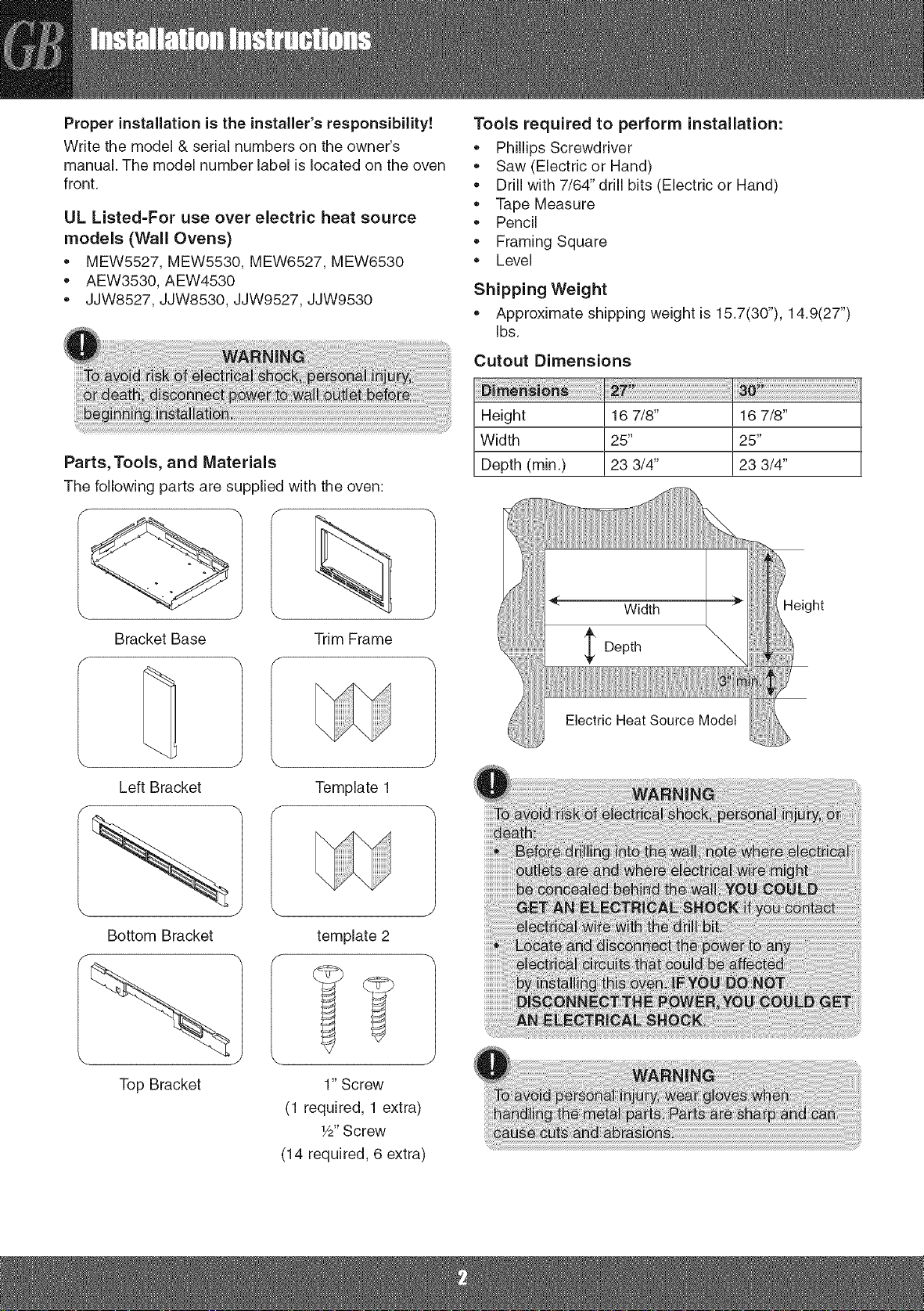
Parts, Tools, and Materials
The following parts are supplied with the oven:
Bracket Base
Left Bracket
Trim Frame
Template 1
Height 16 7/8"
Width 25"
Depth (min.) 23 3/4"
Electric Heat Source Model
16 7/8"
25"
23 3/4"
Height
Bottom Bracket
Top Bracket
template 2
1" Screw
(1 required, 1 extra)
1/2"Screw
(14 required, 6 extra)
Page 3
Electrical rating of this oven:
,, 120 VAC @ 60 Hz
13 A / 1100 W (USA) / 1000 W (CANADA)
You need a DEDICATED 120 VAC, 60 Hz, 20 A
(USA) / 15A (CANADA), fused electrical supply
(located in the cabinet with the microwave as close
as possible to the microwave) serving only the
microwave.
Check with a qualified electrician if you are not
sure whether the oven is properly grounded or if
you do not completely understand the grounding
instructions.
Do not use a fuse in the neutral or grounding circuit.
Save these instructions for the local electrical
inspectors use.
If there is an electrical short circuit, grounding
reduces the risk of electrical shock by providing an
escape wire for the electric current. This appliance is
equipped with a cord having a grounding wire with a
grounding plug.
Place the plug into a properly installed and grounded
outlet.
o Amana does not recommend use of an extension
cord.
Keep the power cord dry and do not pinch or crush
it.
Do not, under any circumstances, remove the power
supply cord grounding prong!
This appliance MUST be grounded!
Do not expose yourself to excessive
microwave energyt
• DO NOT try to operate the microwave oven with the
door open.
• DO NOT tamper with or defeat the safety interlocks.
• DO NOT place objects between the microwave oven
front face and the door.
• DO NOT allow soil or cleaner residue to build up on
the flat surfaces around the microwave oven door.
DO NOT operate the microwave oven if it is
damaged.
The microwave oven door must close properly to
operate safely.
DO NOT USE THE MICROWAVE OVEN:
• If the door is bent.
If the hinges or latches are broken or loose.
If the door seals, sealing surfaces or glass is broken.
DO NOT ATTEMPT TO ADJUST OR REPAIR THE
OVEN YOURSELF!
• It should be adjusted and repaired by a qualified
technician who can check for microwave leakage
after repairing the oven.
/f
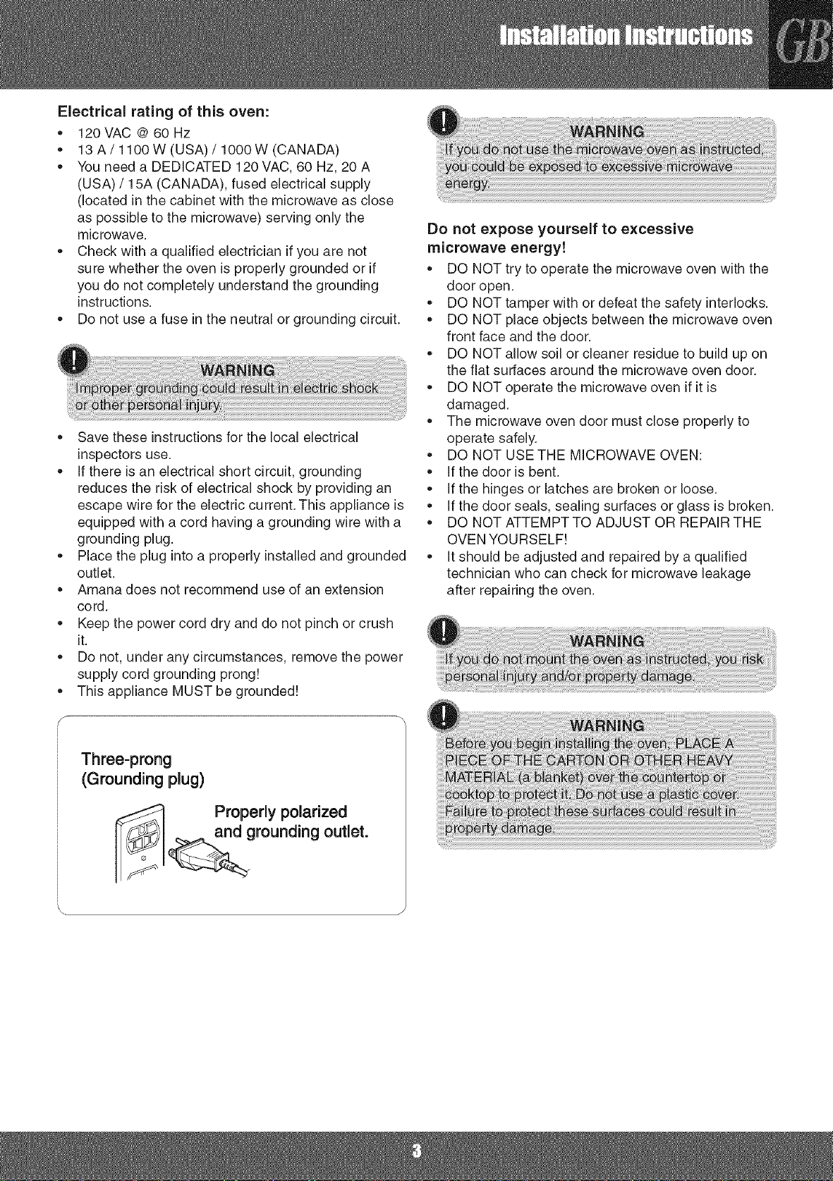
Three-prong
(Grounding plug)
Properly polarized
and grounding outlet.
Page 4
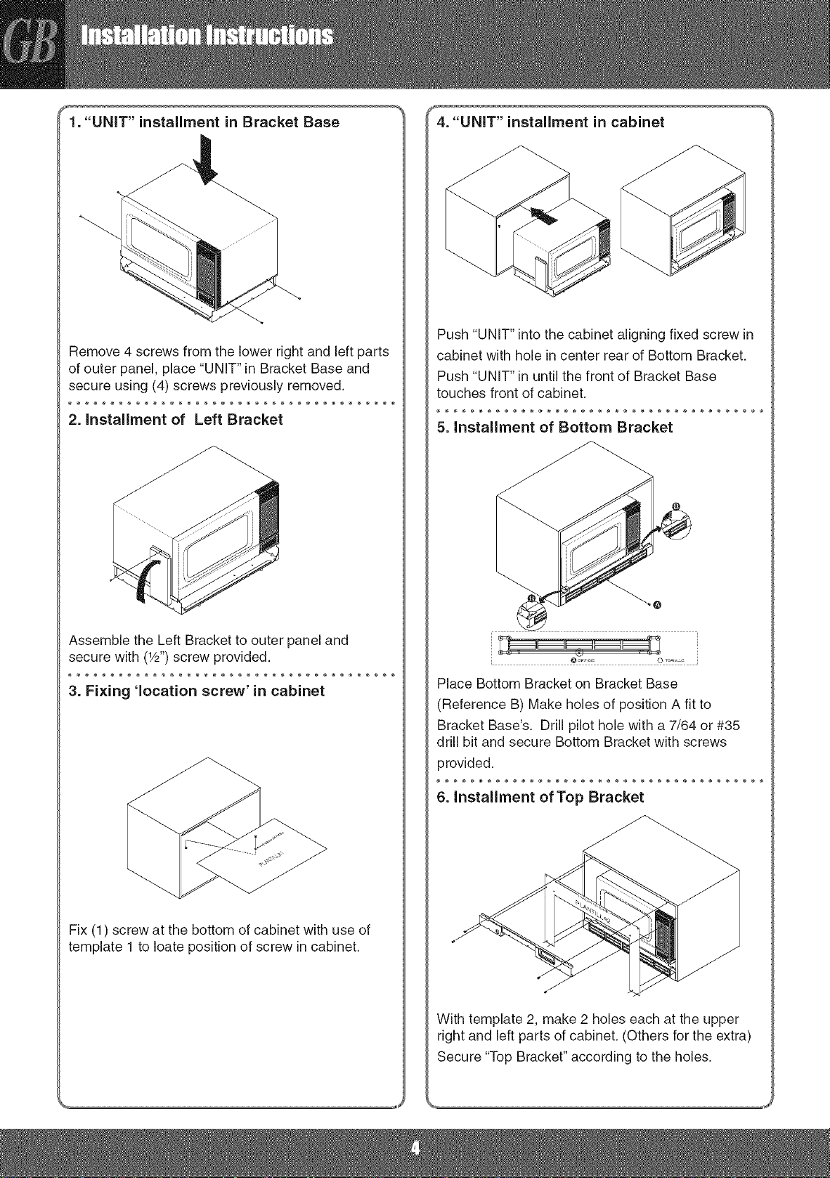
_. "UNIT" installment in Bracket Base
Remove 4 screws from the lower right and left parts
of outer panel, place "UNIT" in Bracket Base and
secure using (4) screws previously removed.
4. "UNIT" installment in cabinet
Push "UNIT" into the cabinet aligning fixed screw in
cabinet with hole in center rear of Bottom Bracket.
Push "UNIT" in until the front of Bracket Base
touches front of cabinet.
2. installment of Left Bracket
Assemble the Left Bracket to outer panel and
secure with (W') screw provided.
3. Fixing 'location screw' in cabinet
5. installment of Bottom Bracket
Place Bottom Bracket on Bracket Base
(Reference B) Make holes of position A fit to
Bracket Base's. Drill pilot hole with a 7/64 or #35
drill bit and secure Bottom Bracket with screws
provided.
6. installment of Top Bracket
Fix (1) screw at the bottom of cabinet with use of
template 1 to Ioate position of screw in cabinet.
With template 2, make 2 holes each at the upper
right and left parts of cabinet. (Others for the extra)
Secure "Top Bracket" according to the holes.
Page 5
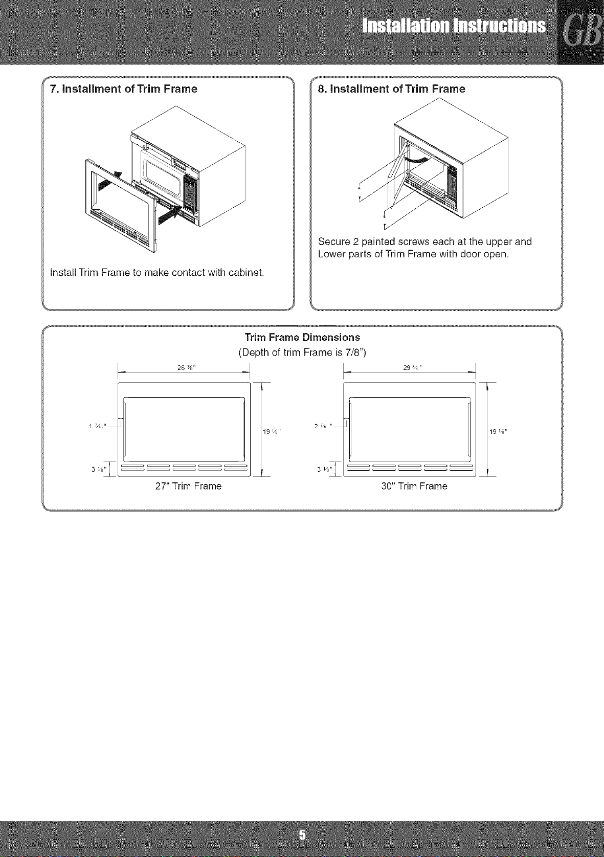
7. Installment of Trim Frame
Install Trim Frame to make contact with cabinet.
Trim Frame Dimensions
(Depth of trim Frame is7/8")
26 %"
_1111,1,1,1,1,
8. installment of Trim Frame
Secure 2 painted screws each at the upper and
Lower parts of Trim Frame with door open.
29 3/4"
17/11r_"
27" Trim Frame
19 14"
27/_ ,_
30" Trim Frame
iiiiuii
Page 6

Page 7

Uneinstallationcorrecterelevede la responsabilit_de
I'installateur!
Inscrivezlesnumerosde modeleetde serie dansle manuel
d'utilisation.Eetiquettedunumerode modeleestapposee
I'avantdufour.
Homologation UL-A utiliser sur des modeles a source
de chaleur electrique (fours murau×)
• MEW5527,MEW5530,MEW6527,MEW6530
° AEW3530,AEW4530
° JJW8527,JJW8530,JJW9527,JJW9530
Pieces, outils et materiaux
Lespiecessuivantessent fourniesavecle four:
Outils necessaires pour effectuer I'installation :
,, TournevisPhillips
,, Scie (electriqueoumanuelle)
,, Perceuseavecmechesde 7/64"(electriqueoumanuelle)
,, Ruban a mesurer
" Crayon
,, Equerredecharpentier
• Niveau
Poids a I'exp_dition
,, Le poidsapproximatifestde 7,12kg (30"),6,75 kg(27").
Dimensions de d_coupe
Hauteur 167/8" 167/8"
Largeur 25" 25"
Profondeur(min.) 23 3/4" 23 3/4"
Basedusupport
\
Supportgauche
Supportinferieur
-lauteur
B&tid'encastrement
Modelea.sourcedechaleurelectrique
Gabarit1
Gabarit 2
\
Supportsuperieur
1"Support
(1requise, 1 supplementaire)
Vis W'
(14 requises, 6
supplementaires)
Page 8

Caracteristiques electriques de ce four :
• 120V c.a.&60 Hz
• 13A / 1100W (Etats-Unis)/1000W (Canada)
• Vousdevezutiliserune alimentationelectrique_.fusible
RESERVEEde 120V c.a., GOHz,20A (Etats-Unis)/15A
(Canada)(situeedans rarmoireavecle fourµ-ondes,
lepluspres possibledu four) desservantuniquementlefour&
micro-ondes.
• Sivous n'_tespascertainde laraise_.laterre du four ou
necomprenezpas touteslesinstructionsde raise&la terre,
consultezun electricienqualifi&
,, N'utilisezpasdefusibledartsle circuitneutreou de raise&la
terre.
• Conservezces instructionsenvue de leurutilisationparun
inspecteurenelectricitelocal.
• Encas de court-circuit,laraiseb,laterre reduitle risquede
chocelectriqueen foumissantuncircuitde fuiteaucourant
electrique.Cet appareilestequiped'uncordondote d'un fil
de masseetd'une prisede terre.
• Branchezla fichedansune prisecorrectementinstalleeet
raiseb,la terre.
• Amanad_conseille I'utilisation d'une rallonge _lectrique,
• Gardezle cordond'alimentationausecet evitezde le pincer
oude le comprimer.
,, Ne retirez,enaucuncas, la brochedemassedu cordon
d'alimentation!
• CetappareilDOlT _tremis&la terre!
Ne vous exposez pas a une energie
microondes excessive t
,, Ne PAS utiliser le four Iorsque la porte est ouverte.
,, Ne JAMAIS demonter ou neutraliser le systeme de
verrouillage.
,, Ne PAS placer d'objets entre la face avant du four b.
micro-ondes et la porte.
,, Ne PAS laisser s'accumuler de la salete ou des
residus de produit de nettoyage sur les surfaces
planes autour de la porte du four & micro-ondes.
,, Ne PAS mettre le four en marche s'il est
endommag&
,, Vous devez fermer correctement la porte du four
pour I' utiliser en toute securit&
,, NE PAS UTILISER LE FOUR A MICRO-ONDES
,, Si la porte est pliee.
,, Si les charnieres ou les Ioquets sont casses ou
desserres.
,, Si les joints de la porte, les surfaces d'etanch6ite ou
la vitre sont casses.
,, N'ESSAYEZ PAS DE REGLER NI DE REPARER LE
FOUR VOUS-MEME !
,, Les reglages et reparations doivent _tre confies &
un technicien qualifie qui verifiera la presence d'une
eventuelle fuite a micro-ondes apres avoir repar6 le
four.
f
Prise de terre & trois broches
Prise de terre
correctement polaris_e.
Page 9

1. Installation de r"UNITE" dans la base du support
Retirezles 4vis des partiesinf@ieuresgaucheet droite
du panneauexterieur,placezI'"UNITE"danslabasedu
support etfixez-laa I'aidedes(4)vis que vousavezretirees
prec6demment.
4. installation de r"UNITE" darts I'armoire
PoussezI"'UNITE"dans rarmoire,en prenantsoind'aligner
lesvisfixees dansle cabinetsur letrouarri@ecentraldu
supportinf@ieur.
PoussezI"'UNITE"jusqu'ace que ravantde la basedu
supporttoucheI'avantdeI'armoire.
2. installation du support gauche
Montezle supportgauchesur lepanneauext@ieuretfixez-le
raide dela vis (W')fourniea ceteffet.
3. Fixation de la"vis d'emplacement" darts I'arrnoJre
5. installation du support inf_rieur
Placezlesupport inferieursur labase du support(Ref@ence
B) Faitescorrespondrelestrousen positionA
avecceux de la basedusupport. Percezun trou de guidage
&I'aided'unemeche7/64ou #35et fixezle supportinferieur
&I'aidedesvis foumies &ceteffet.
6. installation du support superieur
Fixezune (1)vis au bas de I'armoireenutilisantle gabarit 1
pourrep@erI'emplacementappropriedansI'armoire.
A I'aidedu gabarit2,percez2 trousau niveaudes parties
sup@ieureet inferieuredeI'armoire.(Lesautressenten
supplement.)
Fixezle "supportsuperieur"conformementauxtrous.
Page 10

7. Installation du b_ti d'encastrement
Installezle b&tid'encastrementdesorte qu'ilsoiten contact
avec I'armoire.
Dimensions du b_ti d'encastrement
(Laprofondeurdu b_.tid'encastrementestde7/8")
26 7/8"
La portedufouretantouverte,fixez2 vis peintesau niveau
despartiessup@ieureetinf@ieuredu b&tid'encastrement.
29 ¾ "
1 7/t6"
BAti d'encastrement 27"
19 1/8"
27/R ,,
19 1f8"
r
B&ti d'encastrement 30"
,,uii
Page 11

Page 12

iLa instalaci6nadecuadaes responsabilidaddel instaJadort
Anotelos n0merosde seriey modeloenel manual delusuario.El
r6tulodel nOmerode modeloestb.ubicadoenelfrentedel homo.
Certificacion UL-Para utilizar sobre los rnodelos de
fuente de calor electrica (Homos de pared)
" MEW5527,MEW5530,MEW6527,MEW6530
• AEW3530,AEW4530
• JJW8527,JJW8530,JJW9527,JJW9530
Piezas, herramientas y materiales
Lassiguientespiezassesuministranjuntocon el homo:
f
Herramientas requeridas para realizar la instalacion:
• DestornilladorPhillips
,, Sierra(Electricao Manual)
,, Taladroconmechasde 7/64"(Electricoo Manual)
,, Cintade medir
• Lapiz
• Enmarcador
• Nivel
Peso de embarque
,, El pesode embarqueaproximadoes 15,7 (30"),14,9 (27")
Ibs.
Dimensiones de torte
Altura 167/8" 167/8"
Ancho 25" 25"
Profundidad(rain.) 23 3/4" 233/4"
\
Soportede mensula
Marcode moldura
I I
Mensulaizquierda Plantilla1
Mensulainferior
f
\
Mensulasuperior
(1 requerido,1adicional)
(14requeridos,6 adicionales)
Ancho \ltura
Modelo de fuente de ca!or
plantilla2
1"Tornillo
TornillodeY2"
Page 13

Valores el6ctricos nominales de este homo:
,, 120VAC@60Hz
• 13A / 1100W (EE.UU.)/ 1000W(Canadb.)
• Necesitauna alimentaci6nelectricacon fusibleDEDICADA
de 120VAC,60 Hz, 20A (EE.UU.)/15A (Canada),(ubicada
enel gabineteconel microondasIomascercaposibledel
microondas)clueabastezcas61oalmicroondas.
,, Consulteconunelectricistacalificadosi no estasegurodesi
elhomo est,.conectadoa tierrade maneraadecuadaosi no
entiendepercompletelasinstruccionesde conexi6na tierra.
• No utiliceunfusibleen elcircuito neutralodeconexi6na
tierra.
,, Guardeestasinstruccionesparause delos inspectoresde
electricidadlocales.
• Si hayun cortocircuitoelectrico,laconexi6na tierrareduce
el riesgodedescargaelectricaya que ofreceun cablede
escapeparalacorrienteelectrica.Esteelectrodomesticoestb,
equipadoconun cableque tieneunconductoratierracon un
enchufeconconexi6na tierra.
• Conecteel enchufea un tomacorrientequeeste
correctamenteinstaladoyconectadoa tierra.
• Amanano recomiendael ueo de un cableproiongador,
• Mantengael cablede alimentaci6nsecoy no Ioaprieteni Io
aplaste.
" iBajo ningunacircunstanciaquitela terminaldeconexi6na
tierradelcable de alimentaci6nel6ctrica!
• iEsteelectrodomesticoDEBEestarconectadoa tierra!
iNo se exponga a energia de microondas
excesivat
• NO intente poner en funcionamiento el microondas
con la puerta abJerta.
,, NO altere ni modifique las trabas de segufidad.
,, NO coloque objetos entre la parte delantera del
homo de microondas y la puerta.
,, NO deje que se acumule suciedad o residuos de
limpiadores en las superficies planas alrededor de la
puerta del microondas.
,, NO ponga en funcionamiento el homo si esta
da_ado.
,, La puerta del homo de microondas debe cerrar bien
para que funcione en forma segura.
,, NO UTILICE EL HORNO DE MICROONDAS:
,, Si la puerta est,. doblada.
,, Si las bisagras o pestillos estan rotos o sueltos.
,, Si estan rotas las juntas de la puerta, las superficies
de sellado o el vidrio.
" iNO INTENTE AJUSTAR O REPARAR EL HORNO
USTED MISMO!
,, Debe set ajustado y reparado pot un t6cnico
calificado que pueda verJficar que no haya fugas de
microondas despues de reparar el homo.
f
Tres pines
(enchufe con ¢onexi6n a tierra)
Tomacorriente correotamente
izado y coneotado a tierra.
Page 14

m6nsula
Quitelos 4 tomillos de las piezasderechae izquierda
inferioresdelpanelexterior,coloquela"UNIDAD"enel
Soportede mensulay asegurelautilizandolos (4) tomillos
previamentequitados.
2. Instalaci6n de la M6nsula Jzquierda
Empujela "UNIDAD"dentrodel gabinetealineandoel tomillo
posicionadoenel gabineteconun orificioen elcentre de
la partetraseradela Mensulainferior.Empujela "UNIDAD"
hastaque elfrentedel Soportede mensulatoqueelfrente
delgabinete.
5. InstalacJbnde la m6nsula inferior
Ensamblela Mensulaizquierdaenel panelexteriory
asegurelocon el tornillo (deW') provisto.
3. Colocar el 'tornillo de posicion' en el gabJnete
Coloque(1)tomilloen laparteinferiordel gabineteutilizando
laplantilla1para ubicarla posici6ndel tomilloen el gabinete.
Coloquela Mensulainferiorenel Soportede mensula
(ReferenciaB)Hagaorificiosparacolocarla piezaA en los
Soportesde mensulas. Perforeunorificiopilotoconuna
mechade 7/64o#35 y asegurela Mensulainferiorcon los
tomillosprovistos.
6. InstalacJbnde la M6nsula superior
Conla plantilla2, haga2 orificios unoencada la pieza
derechae izquierdasuperiordelgabinete.(Otrosparalos
adicionales)
Asegurela"Mensulasuperior"seg_nlosorificios.
Page 15

7. Instalacibn del Marco de moldura
Instaleel Marcode molduraparaquehagacontactocon el
gabinete.
Dimensiones del marco de moldura
(Laprofundidaddelmarcode molduraes 7/8")
26 7/8"
Asegurelos 2 tomillos pintadosuno en lapieza superiory el
otto en lainferiordel Marcode molduraconla puertaabierta.
29 ¾ "
1 7/t6"
Marco de moldura de 27"
191/8"
27/R ,,
191f8"
r
Marco de moldura de 30"
Page 16

 Loading...