

JENNAIR JJW2830LM, JJW2830LL, JJW2427IL Installation Instructions

INSTALLATION INSTRUCTIONS
27" (68.6 CM) AND 30" (76.2 CM) ELECTRIC SINGLE AND
DOUBLE BUILT-IN OVEN
INSTRUCTIONS D’INSTALLATION
FOUR ÉLECTRIQUE ENCASTRÉ
27" (68,6 CM) ET 30" (76,2 CM) - SIMPLE ET DOUBLE
Table of Contents/Table des matières
BUILT-IN OVEN SAFETY ................................................................2
INSTALLATION REQUIREMENTS .................................................3
Tools and Parts .............................................................................3
Location Requirements ................................................................3
Electrical Requirements ...............................................................6
INSTALLATION INSTRUCTIONS ...................................................7
Prepare Built-In Oven ...................................................................7
Remove Oven Door(s) ..................................................................7
Replace Oven Door(s) ..................................................................7
Positioning Oven Feet for Multiple Cabinet Cutout Heights .......8
Make Electrical Connection .......................................................13
Install Oven .................................................................................14
Install Warming Drawer Deector Kit (Only
for Ovens Installed above Warming Drawers) ...........................15
Complete Installation .................................................................16
SÉCURITÉ DE LA TABLE DE CUISSON .....................................17
EXIGENCES D’INSTALLATION ...................................................17
Outillage et pièces ......................................................................17
Exigences d’emplacement .........................................................17
Spécications électriques ..........................................................20
INSTRUCTIONS D’INSTALLATION .............................................21
Préparation du four encastré .....................................................21
Dépose de la/des porte(s) du four .............................................21
Réinstallation de la/des porte(s) du four ....................................22
Positionnement des pieds du four pour des
ouvertures d’encastrement de hauteur différente .....................23
Raccordement électrique ...........................................................27
Installation du four ......................................................................28
Installation de l’ensemble dedéecteur
du tiroir-réchaud (uniquement pour les fours
installés au-dessus d’un tiroir-réchaud) .....................................30
Achever l’installation ..................................................................30
IMPORTANT:
Save for local electrical inspector’s use.
IMPORTANT:
À conserver pour consultation par l’inspecteur local des installations électriques.
W11235621B
BUILT-IN OVEN SAFETY
2

INSTALLATION REQUIREMENTS
Tools and Parts
Gather the required tools and parts before starting installation.
Read and follow the instructions provided with any tools listed
here.
Tools Needed
■ Phillips screwdriver
■ Measuring tape
■ Hand or electric drill (for wall cabinet installations)
■ 1" drill bit (for wall cabinet installations)
■ Level
■ Flat-blade screwdriver
Parts Needed
■ UL listed or CSA approved conduit connector
■ UL listed wire connectors
■ Warming Drawer Deector Kit (for ovens installed
above a warming drawer)
Black 27" (68.6 cm) kit
Stainless steel 27" (68.6 cm) kit
Black 30" (76.2 cm) kit
Stainless steel 30" (76.2 cm) kit
To order, see the “Assistance or Service” section
of the Use and Care Guide.
■ Flush Installation Kit (for single and double installed
at ush installation)
Black 27" (68.6 cm) kit
Stainless steel 27" (68.6 cm) kit
Black 30" (76.2 cm) kit
Stainless steel 30" (76.2 cm) kit
To order, see the “Assistance or Service” section
of the Use and Care Guide.
Parts Supplied
■ #8-14 x 1" (2.54 cm) screws - single ovens (2),
double ovens (4)
■ #8-18 x 3/8" (9.5 mm) screws - bottom vent (2)
■ #8-18 x 1/4" (6.4 mm) screws - bottom vent trim (4)
■ #8-18 x 3/8" (9.5 mm) screws - double oven feet (4)
■ Bottom vent
■ Bottom vent trim
■ Rear feet - double oven (2)
■ Front feet - double oven (2)
■ Foam strip - single oven*
Check local codes. Check existing electrical supply. See
“Electrical Requirements.”
It is recommended that all electrical connections be made by a
licensed, qualied electrical installer.
*Foam strip not included with double oven.
Location Requirements
IMPORTANT: Observe all governing codes and ordinances.
■ Cabinet opening dimensions that are shown must be used.
Given dimensions provide minimum clearance with oven.
■ Recessed installation area must provide complete enclosure
around the recessed portion of the oven.
■ Grounded electrical supply is required. See “Electrical
Requirements” section.
■ Electrical supply junction box should be located 3" (7.6cm)
maximum below the support surface when the oven is
installed in a wall cabinet. A 1" (2.5 cm) minimum diameter
hole should have been drilled in the right rear or left rear
corner of the support surface to pass the appliance cable
through to the junction box.
NOTE: For undercounter installation, it is recommended
that the junction box be located in the adjacent right or left
cabinet. If you are installing the junction box on rear wall
behind oven, it is recommended that the junction box be
recessed and located in the upper center of the cabinet.
■ Oven support surface must be solid, level, and ush
with bottom of cabinet cutout.
■ Floor must be able to support a single oven weight of
180 lbs (82 kg).
■ Floor must be able to support a double oven weight
of 357 lbs (162 kg).
IMPORTANT: To avoid damage to your cabinets, check
with your builder or cabinet supplier to make sure that the
materials used will not discolor, delaminate, or sustain other
damage. This oven has been designed in accordance with
the requirements of UL and CSA International and complies
with the maximum allowable wood cabinet temperatures of
194°F (90°C).
Undercounter Installation (with Cooktop Installed
Above):
Refer to the Cutout Dimensions for Ovens Installed Under
Cooktop (separate sheet). See product website for list of
cooktop models approved for use above select wall-oven
models.
3
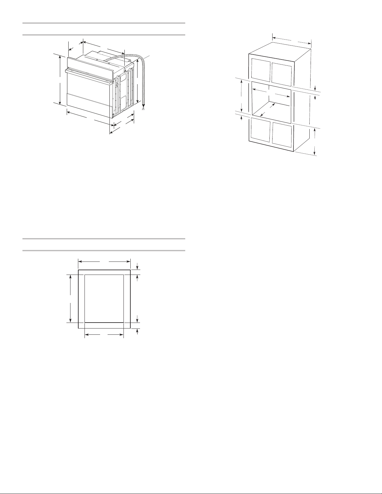
Product Dimensions - Single Ovens
Single Ovens Installed in Cabinet
H
A
B
27" (68.6 cm) models
A. 297⁄8" (75.8 cm) max. overall
height
B. 27" (68.6 cm) overall width
C. JJW2427IM - 263/8" (67.0 cm)
JJW2427IL - 27
D. 23¼" (59.1 cm) max. recessed
depth
E. 27³⁄16" (69.0 cm) recessed height
F. 48" (121.9 cm) flexible conduit
length
G. 257⁄16" (64.6 cm) max. recessed
width
H. 12" (30.5 cm) from back of
control panel to start of strain
relief
3
/16" (69.0 cm)
G
F
E
D
C
30" (76.2 cm) models
A. 297⁄8" (75.8 cm) max. overall
height
B. 30" (76.2 cm) overall width
C. JJW2430IM - 263/8" (67.0 cm)
JJW2430IL - 273/16" (69.0 cm)
D. 23¼" (59.1 cm) max. recessed
depth
E. 27³⁄16" (69.0 cm) recessed height
F. 48" (121.9 cm) flexible conduit
length
G. 287⁄16" (72.2 cm) max. recessed
width
H. 12" (30.5 cm) from back of
control panel to start of strain
relief
D
F
G
E
27" (68.6 cm) models
A. 27" (68.6 cm) min. cabinet
width
B. 2³⁄16" (5.5 cm) top of cutout to
bottom of upper cabinet door
C. 32" (81.3 cm) bottom of cutout
to floor
D. 25½" (64.8 cm) cutout width
E. 1½" (3.8 cm) min. bottom of
cutout to top of cabinet door
F. 28" (71.2 cm)* recommended
cutout height
G. 24" (60.7 cm) cutout depth
A
B
C
30" (76.2 cm) models
A. 30" (76.2 cm) min.
cabinet width
B. 2³⁄16" (5.5 cm) top of cutout to
bottom of upper cabinet door
C. 32" (81.3 cm) bottom
of cutout to floor
D. 28½" (72.4 cm) cutout width
E. 1½" (3.8 cm) min. bottom of
cutout to top of cabinet door
F. 28" (71.2 cm)* recommended
cutout height
G. 24" (60.7 cm) cutout depth
Cabinet Dimensions - Single Ovens
A
E
D
27" (68.6 cm) models
A. 27" (68.6 cm) min. cabinet
width
B. 1½" (3.8 cm) min. top of cutout
to underside of countertop
C. 5¼" (13.3 cm) bottom of
cutout to floor
D. 25½" (64.8 cm) cutout width
E. 28" (71.2 cm) min.cutout height
30" (76.2 cm) models
A. 30" (76.2 cm) min. cabinet
width
B. 1½" (3.8 cm) min. top of cutout
to underside of countertop
C. 5¼" (13.3 cm) bottom of
cutout to floor
D. 28½" (72.4 cm) cutout width
E. 28" (71.2 cm) min.cutout height
*NOTE: The cutout height can be between 271/4 " and 297/16"
(69.2 cm and 74.8 cm) for single ovens.
B
C
4
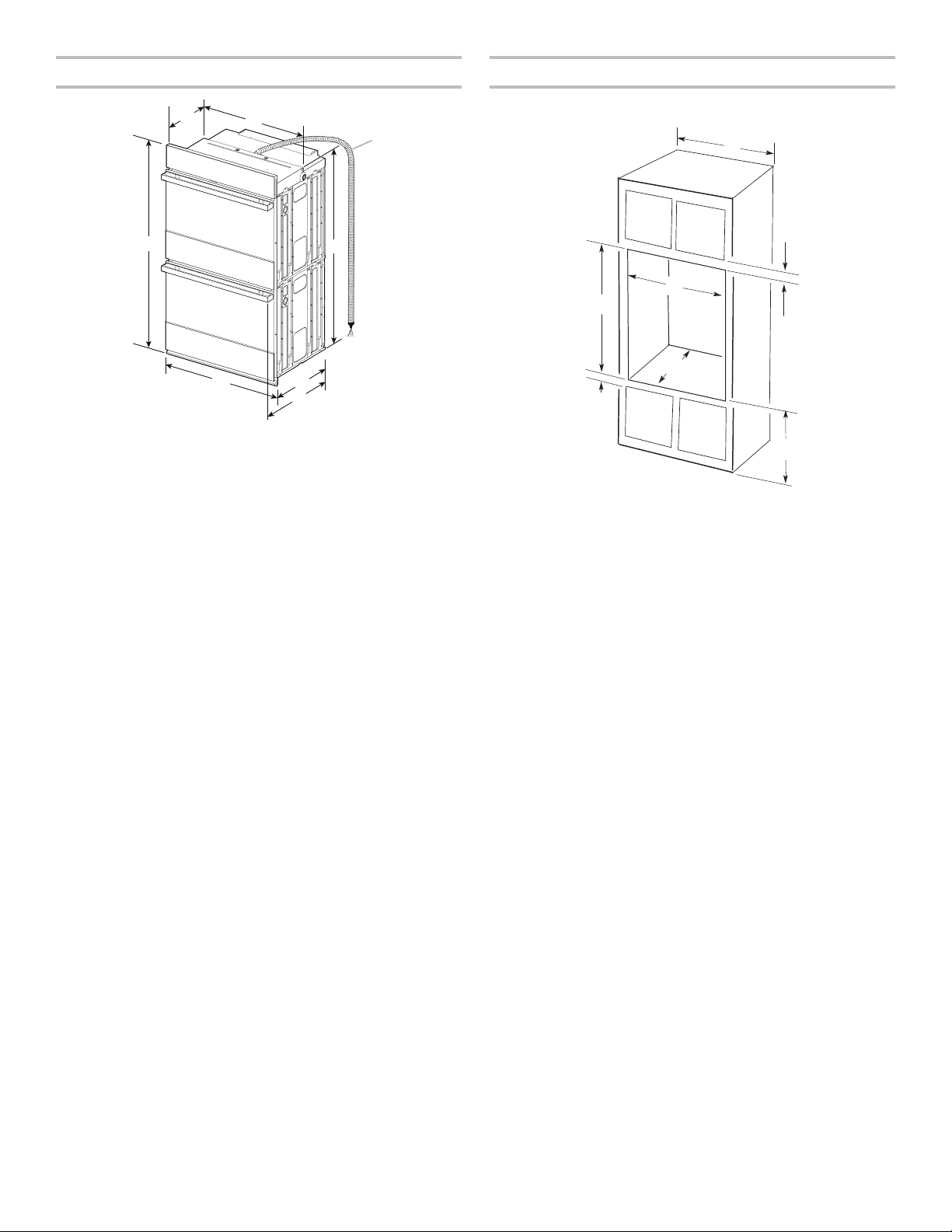
Product Dimensions - Double Ovens Cabinet Dimensions - Double Ovens
F
H
A
B
27" (68.6 cm) models
A. 52³⁄8" (133 cm) max. overall
height
B. 27" (68.6 cm) overall width
C. JJW2827IM - 263/8" (67 cm)
JJW2827IL - 273/16" (69 cm)
D. 23¼" (59.1 cm) max. recessed
depth
E. 49¹⁄4" (125.1 cm) recessed
height
F. 66" (167.6 cm) flexible conduit
length
G. 257⁄16" (64.6 cm) max. recessed
width
H. 12" (30.5 cm) from back of
control panel to start of strain
relief
G
E
D
C
30" (76.2 cm) models
A. 52³⁄8" (133 cm) max. overall
height
B. 30" (76.2 cm) overall width
C. JJW2830IM - 263/8" (67 cm)
JJW2830IL - 273/16" (69 cm)
D. 23¼" (59.1 cm) max. recessed
depth
E. 49¹⁄4" (125.1 cm) recessed
height
F. 66" (167.6 cm) flexible conduit
length
G. 287⁄16" (72.2 cm) max. recessed
width
H. 12" (30.5 cm) from back of
control panel to start of strain
relief
Double Ovens Installed in Cabinet
A
D
F
G
E
27" (68.6 cm) models
A. 27" (68.6 cm) min.
cabinet width
B. 2³⁄16" (5.5 cm) top of cutout to
bottom of upper cabinet door
C. 14³⁄4" (37.5 cm) bottom
of cutout to floor is
recommended.
4"-14³⁄4" (10.2-37.5 cm)
bottom of cutout to floor is
acceptable.
D. 25¹⁄2" (64.8 cm) cutout width
E. 1¹⁄2" (3.8 cm) min. bottom of
cutout to top of cabinet door
F. 50¹⁄4" (127.6 cm)*
recommended cutout height
G. 24" (60.7 cm) cutout depth
30" (76.2 cm) models
A. 30" (76.2 cm) min.
cabinet width
B. 2³⁄16" (5.5 cm) top of cutout to
bottom of upper cabinet door
C. 14³⁄4" (37.5 cm) bottom
of cutout to floor
is recommended.
4"-14³⁄4" (10.2-37.5 cm)
bottom of cutout to floor is
acceptable.
D. 28¹⁄2" (72.4 cm) cutout width
E. 1¹⁄2" (3.8 cm) min. bottom of
cutout to top of cabinet door
F. 50¹⁄4" (127.6 cm)*
recommended cutout height
G. 24" (60.7 cm) cutout depth
B
C
*NOTE: The cutout height can be between 491/2" and 523/16"
(125.7 cm and 132.6 cm) for double ovens.
5
Electrical Requirements
If codes permit and a separate ground wire is used, it is
recommended that a qualied electrical installer determine that
the ground path and the wire gauge are in accordance with local
codes.
Check with a qualied electrical installer if you are not sure the
oven is properly grounded.
This oven must be connected to a grounded metal, permanent
wiring system.
Be sure that the electrical connection and wire size are adequate
and in conformance with the National Electrical Code, ANSI/
NFPA 70-latest edition or CSA Standards C22.1-94, Canadian
Electrical Code, Part 1 and C22.2 No. O-M91-latest edition, and
all local codes and ordinances.
A copy of the above code standards can be obtained from:
National Fire Protection Association
Electrical Connection
To properly install your oven, you must determine the type of
electrical connection you will be using and follow the instructions
provided for it here.
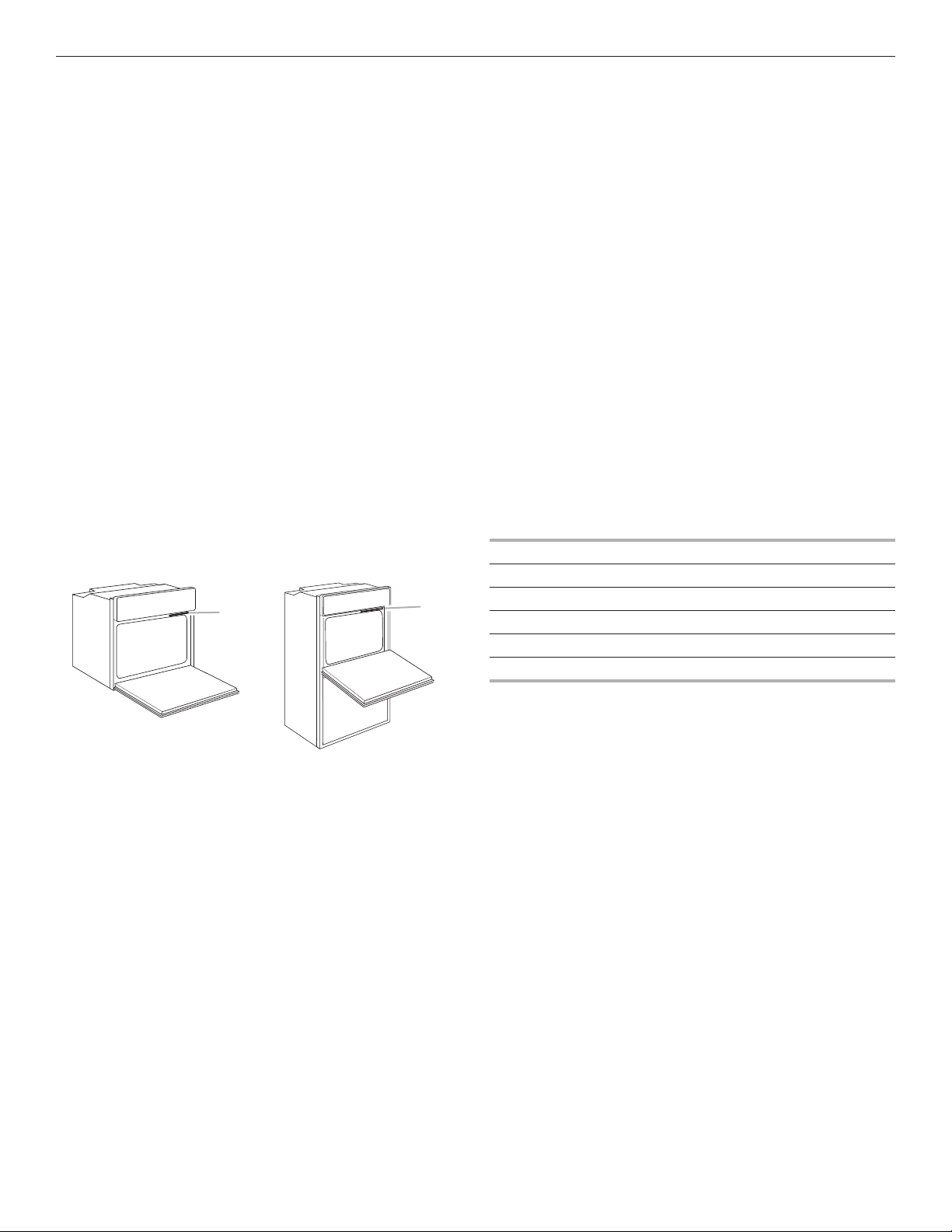
■ Oven must be connected to the proper electrical voltage and
frequency as specied on the model/serial/rating plate. The
model/serial/rating plate is located under the control panel
on single ovens and under the control panel on the upper
oven cavity on double ovens. See the following illustrations.
1 Batterymarch Park
Quincy, MA 02169-7471
CSA International
8501 East Pleasant Valley Road
Cleveland, OH 44131-5575
A
A
■ Models rated from 7.3 to 9.6 kW at 240 V (5.4 to 7.4 kW
at 208 V) require a separate 40 A circuit. Models rated at
4.8kW and below at 240 V (3.6 kW and below at 208 V)
require a separate 20 A circuit.
■ A circuit breaker is recommended.
■ Connect directly to the circuit breaker box (or fused
disconnect) through exible, armored or nonmetallic
sheathed, copper cable (with grounding wire). See
“Make Electrical Connection” section.
■ Flexible conduit from the oven should be connected directly
to the junction box.
■ Fuse both sides of the line.
■ Do not cut the conduit. The length of conduit provided
is for serviceability of the oven.
■ A UL listed or CSA approved conduit connector must
be provided.
■ If the house has aluminum wiring, follow the
procedure below:
Connect the aluminum wiring using special connectors
and/or tools designed and UL listed for joining copper to
aluminum.
Follow the electrical connector manufacturer’s recommended
procedure. Aluminum/copper connection must conform with
local codes and industry accepted wiring practices.
For power requirements for models JJW2430I, JJW2427I,
JJW2830I, and JJW2827I refer to the following table.
240 VAC 208 VAC
Model kW kW
JJW2430I
JJW2427I
JJW2830I
JJW2827I
4.1 3.1
4.1 3.1
8.7 6.5
8.7 6.5
Single Oven
A. Model/serial/rating plate
6
Double Oven
A. Model/serial/rating plate
INSTALLATION INSTRUCTIONS
Prepare Built-In Oven
1. Decide on the nal location for the oven. Avoid drilling or
cutting into house wiring during installation.
WARNING
Excessive Weight Hazard
Use two or more people to move and install oven.
Failure to do so can result in back or other injury.
2. To avoid oor damage, set the oven onto cardboard prior
to installation. Do not use handle or any portion of the front
frame for lifting.
3. Remove the shipping materials and tape from the oven.
Remember to keep the corner posts and other materials that
may be needed for installation.
4. Remove the hardware package from inside the bag
containing literature.
5. Remove and set aside racks and other parts from inside the
oven.
6. Move oven and cardboard close to the oven’s nal location.
Remove Oven Door(s)
IMPORTANT: Use two hands to remove oven door. For double
ovens, repeat the process for each door.
1. Prior to removing the oven door, prepare a surface where
you will place it. This surface should be at and covered with
a soft blanket, or use the corner posts from your packaging
material.
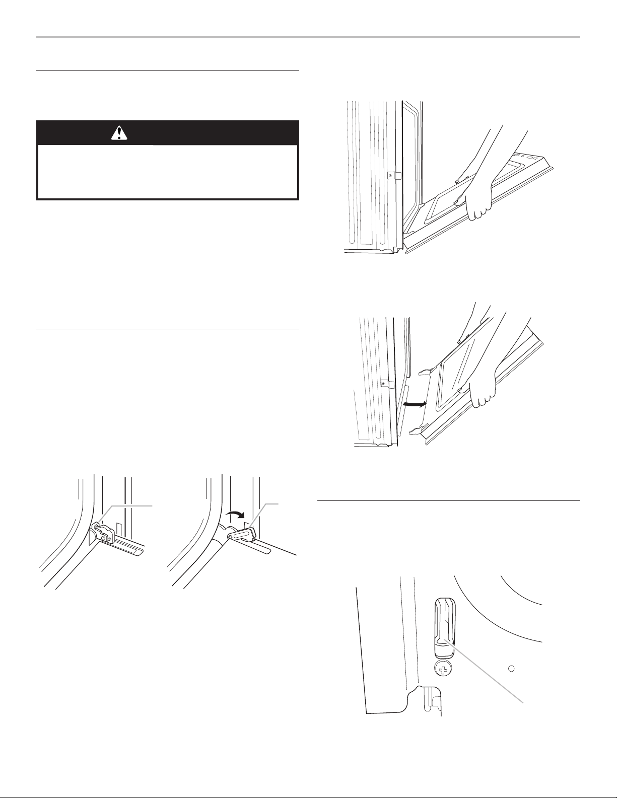
2. Open the oven door.
3. Locate the oven door hinge locks in both corners of the oven
door, and then rotate the hinge locks toward the oven door
to the unlocked position. If the door hinge lock is not rotated
fully (see illustration B), the door will not remove properly.
A
B
4. Partially close the door to engage the door latch locks. The
door will stop at this point.
5. Using two hands, grasp the edges of the oven door. Lift and
pull the oven door toward you and remove. You may need to
gently shift door from side to side as you pull.
6. Set the oven door(s) aside on the prepared covered
work surface with the oven door resting on its handle.
7. To continue with the oven installation, go to the “Positioning
Oven Feet for Multiple Cabinet Cutout Heights” section.
Replace Oven Door(s)
1. Using two hands, grasp side edges of door at the midpoint.
Face the oven cavity.
2. Locate the slots on each side of the oven cavity for
the door hinge locks.
A. Oven door hinge lock in
locked position
B. Oven door hinge lock in
partially unlocked position
A
A. Slot in the oven cavity for door hinge lock
7
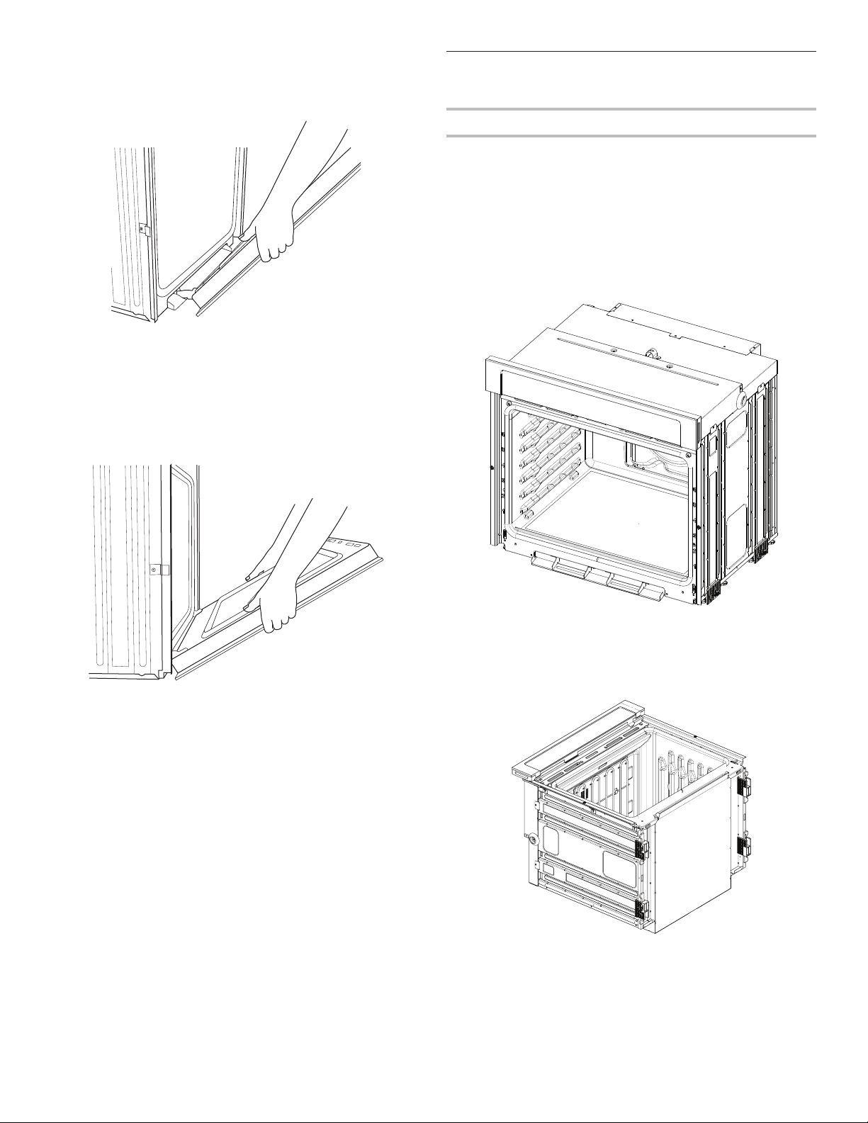
3. At a 45° angle, align door hinges with slots in the lower
front of the oven cavity. Slowly insert door, making
sure you maintain the 45° angle. You will know the
door is engaged in the slot when you feel a slight drop.
4. Lower the oven door to the fully open position. If the oven
door does not open to a full 90°, repeat steps 1 through 3.
5. Locate the oven door hinge locks in the corners of the oven
door, and rotate the hinge locks toward the oven cavity to
the locked position.
See Step 3 (illustration A) in the “Remove Oven Door(s)”
section for proper locked position.
Positioning Oven Feet for Multiple
Cabinet Cutout Heights
Single Ovens
The positioning of the oven feet allow a single oven to be
installed in a cutout height between 26¹5⁄16" and 297⁄16" (68.4 cm
and 74.8 cm). Refer to the following instructions to position the
feet for the size of your cabinet cutout.
Cutout Height Is Between 275⁄8" and 285⁄8"
(70.2 cm and 72.7 cm)
The oven feet do not need to be changed. They are positioned
correctly as received.
Go to the “Make Electrical Connection” section.
6. Close the oven door.
7. When the hinges are properly installed and the door closed,
there should be an even gap between the door and the
control panel. If one side of the oven door is hanging lower
than the other, the hinge on that side is not properly installed.
Cutout Height Is Between 2615/16" and 27¹¹⁄16"
(68.4 cm and 70.3 cm)
1. Using 2 or more people, place the oven on its back on a
covered surface.
8
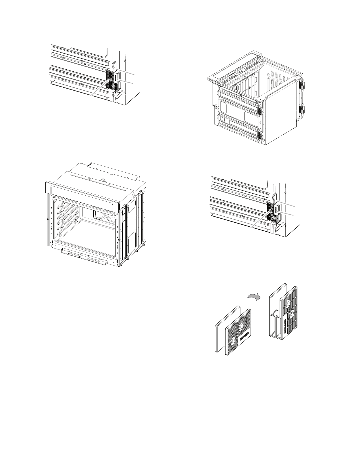
2. Remove the foot from the right front spacer by removing the
#8-18 x 3/8" (9.5 mm) screw.
NOTE: Do not remove the spacer.
A
B
C
A. Spacer
B. Foot
C. #8-18 x 3/8" (9.5 mm) screw
3. In the same manner, remove the feet on the right rear,
left front, and left rear of the oven.
4. Using 2 or more people, place the oven in its upright
position.
Cutout Height Is Between 28¹¹⁄16" and 297⁄16"
(72.8 cm and 74.8 cm)
1. Using 2 or more people, place the oven on its back on a
covered surface.
2. Remove the foot from the right front spacer by removing the
#8-18 x 3/8" (9.5 mm) screw.
NOTE: Do not remove the spacer.
5. Go to the “Make Electrical Connection” section.
A
B
C
A. Spacer
B. Foot
C. #8-18 x 3/8" (9.5 mm) screw
3. Rotate the foot 90°, so the short side of the foot is positioned
toward the top of the oven.
4. Reinstall the foot to the spacer using the #8-18 x 3/8"
(9.5mm) screw previously removed.
5. In the same manner, remove, rotate, and reinstall the feet on
the right rear, left front, and left rear of the oven.
9
6. Using 2 or more people, place the oven in its upright
position.
7. Go to the “Make Electrical Connection” section.
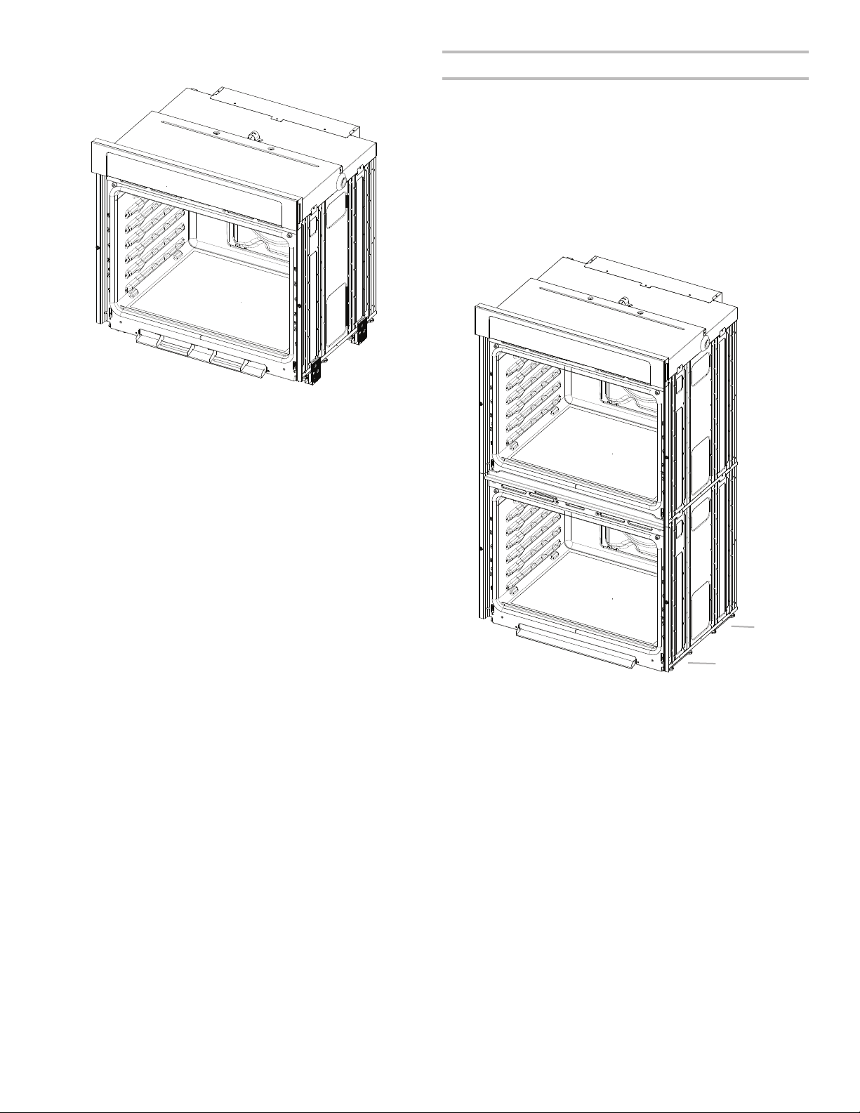
Double Ovens
The positioning of the oven feet allow a double oven to be
installed in a cutout height between 487/8" and 52³⁄16" (124.1 cm
and 132.6 cm). Refer to the following instructions to position the
feet for the size of your cabinet cutout.
Cutout Height Is Between 487⁄8" and 507⁄16"
(124.1 cm and 128.1 cm)
The oven feet do not need to be installed. The oven is congured
correctly as received.
NOTE: Do not remove the spacers.
Go to the “Make Electrical Connection” section.
A. Spacers
A
A
10
 Loading...