

Jenn-Air JES9860BA Series, JES8850BC Series, JES9750BA Series, JES8850BA Series, JES9860BC Series Service Manual
...
Service
This manual is to be used by qualified appliance
technicians only. Maytag does not assume any
responsibility for property damage or personal
injury for improper service procedures done by
an unqualified person.
Electric
Slide-In
Range
This Base Manual covers general information
Refer to individual Technical Sheet
for information on specific models
This manual includes, but is
not limited to the following:
JES8750BA*
JES8850BA*
JES8850BC*
JES9750BA*
JES9800BA*
JES9860BA*
JES9860BC*
JES9900BA*
JES9900BC*
16026926
March 2006
© 2006 Maytag Services
Important Information
Maytag will not be responsible for personal injury or property damage from improper service procedures. Pride and
workmanship go into every product to provide our customers with quality products. It is possible, however, that
during its lifetime a product may require service. Products should be serviced only by a qualified service technician
who is familiar with the safety procedures required in the repair and who is equipped with the proper tools, parts,
testing instruments and the appropriate service information. IT IS THE TECHNICIANS RESPONSIBLITY TO
REVIEW ALL APPROPRIA TE SERVICE INFORMA TION BEFORE BEGINNING REP AIRS.
Important Notices for Servicers and Consumers
!
To avoid risk of severe personal injury or death, disconnect power before working/servicing on appliance to avoid
electrical shock.
To locate an authorized servicer, please consult your telephone book or the dealer from whom you purchased this
product. For further assistance, please contact:
WARNING
Customer Service Support Center
CAIR Center
Web Site Telephone Number
WWW.JENNAIR.COM ............................................. 1-800-536-6247
WWW.MAYTAG.COM ............................................. 1-800-688-9900
WWW.AMANA.COM................................................ 1-800-843-0304
CAIR Center in Canada ................................................ 1-800-688-2002
Recognize Safety Symbols, Words, and Labels
DANGER!
DANGER—Immediate hazards which WILL result in severe personal injury or death.
WARNING!
WARNING—Hazards or unsafe practices which COULD result in severe personal injury or death.
CAUTION!
CAUTION—Hazards or unsafe practices which COULD result in minor personal injury, product or property
damage.
2 16026926 © 2006 Maytag Services

Table of Contents
Important Information ................................................... 2
Important Safety Information
All Appliances .......................................................... 4
Surface Cooking Units ............................................. 4
Ovens ....................................................................... 5
Self-Cleaning Ovens ................................................ 5
Glass/Ceramic Cooking Surfaces ............................ 5
Ventilation Hoods ..................................................... 5
In Case of Fire ......................................................... 5
Surface Element Fire ............................................... 5
Oven Fires ............................................................... 5
Precautions ............................................................. 5
Product Safety Devices ........................................... 6
General Information
Cooking Nomenclature ............................................. 7
Specifications .......................................................... 8
Placement of the Oven ............................................. 8
Do Not Block Air Vents ............................................ 8
Location of Model Number ........................................ 8
Grounding Instructions ............................................. 8
Model Identification .................................................. 8
Service ..................................................................... 8
Parts and Accessories ............................................. 8
Extended Service Plan ............................................. 8
Range Description ................................................... 9
Troubleshooting Procedures
Troubleshooting Chart ............................................ 10
Description of Fault Codes for EOC III .................. 11
Fault Code Chart.................................................... 11
Oven Sensor, Meat Probe and ...................................
Cooling Fan Temperature Charts ...................... 12
Testing Procedures
Component Testing Procedures ............................. 13
Cooling Fan Temperatures ..................................... 16
Control Testing Procedures ................................... 17
Electronic Oven Control (EOC III)
Testing Procedures .......................................... 20
Relay Logic for EOC III ......................................... 23
Quick Test Mode for EOC III.................................. 24
Oven Sensor and Meat Probe Resistances ............ 24
Description of Fault Codes for EOC III .................. 25
Disassembly Procedures
Removing and Replacing Range ............................ 26
Cartridge Assembly Removal (Select Models) ........ 26
Maintop Assembly Removal ................................... 26
Control Panel Assembly Removal ........................... 26
Electronic Control Replacement ............................. 26
Infinite Switch Removal .......................................... 26
Bottom Access Panel Removal (Select Models) ..... 26
Indicator Light Removal ......................................... 27
Meat Probe Receptacle
Replacement (Select Models) ........................... 27
Back Panel Removal .............................................. 27
Cooling Fan Replacement ...................................... 27
Hidden Bake Element
Replacement (Select Models) ........................... 27
Bake Element Replacement (Select Models) .......... 27
Broil Element Replacement .................................... 27
Downdraft Blower Motor Removal (Select Models) . 27
Convection Motor Removal (Select Models) ........... 28
Convection Element Removal (Select Models) ....... 28
Oven Sensor Replacement ..................................... 28
Oven Light Bulb/Oven Light Socket Replacement .. 28
Oven Vent/Smoke Eliminator Removal ................... 28
Oven Hi-Limit Thermostat Replacement ................. 28
Oven Door Latch Replacement .............................. 29
Warming Drawer Removal (Select Models) ........... 29
Warming Drawer Element
Removal (Select Models) .................................. 29
Warming Drawer Hi-Limit Switch
Replacement (Select Models) ........................... 29
Oven Door Removal ............................................... 29
Oven Door Hinge Removal ..................................... 29
Oven Door Disassembly ........................................ 29
Warming Drawer Disassembly (Select Models) ..... 30
Warming Drawer Track
Disassembly (Select Models) ........................... 30
Oven Door, Warming Drawer and
Access Panel Disassembly .............................. 30
Appendix A: Installation Instructions .......................... A-2
Appendix B: Use and Care Information ..................... B-2
© 2006 Maytag Services 16026926 3
Important Safety Information
!
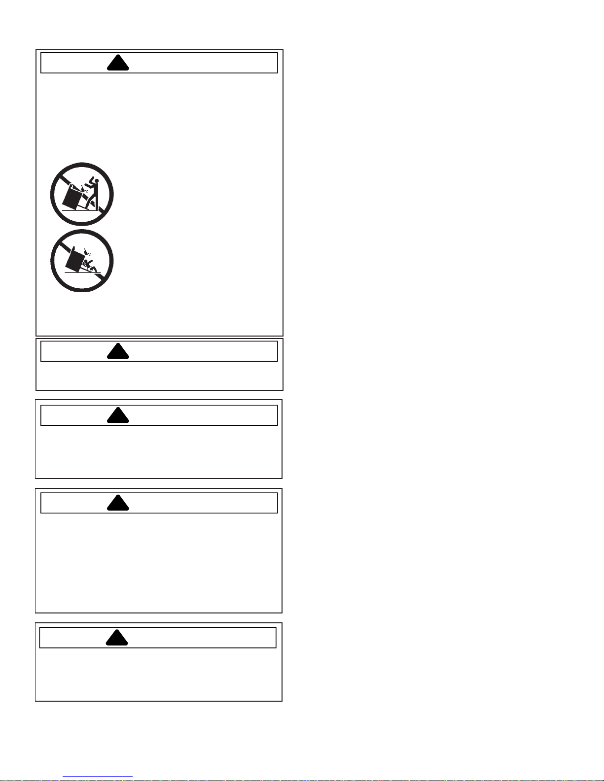
WARNING
To reduce the risk of the appliance tipping, it must be
secured by a properly installed anti-tip bracket(s). To
make sure bracket has been installed properly, remove
the storage drawer and look under the range with a
flashlight. Bracket(s) must be engaged in the rear
corner of the range.
• ALL RANGES CAN TIP
• INJURY TO PERSONS
COULD RESULT
• INSTALL ANTI-TIP
BRACKET(S) PACKED
WITH RANGE
• SEE INSTALLATION
INSTRUCTIONS
!
WARNING
To avoid personal injury, do not sit, stand or lean on
oven door or oven drawer.
ALL APPLIANCES
1. Proper Installation—Be sure your appliance is
properly installed and grounded by a qualified
technician.
2. Never Use Your Appliance for Warming or Heating
the Room.
3. Do Not Leave Children Alone—Children should not
be alone or unattended in the area where the
appliance is in use. They should never be allowed to
sit or stand on any part of the appliance.
4. Wear Appropriate Apparel—Loose fitting or hanging
garments should never be worn while using
appliance.
5. User Servicing—Do not repair or replace any part of
the appliance unless specifically recommended in the
manual. All other servicing should be referred to a
qualified technician.
6. Storage in or on Appliance—Flammable materials
should not be stored in an oven or near surface
units.
7. Do Not Use Water on Grease Fires—Smother fire or
flame, or use dry chemical or foam-type extinguisher.
8. Use Only Dry Potholders—Moist or damp potholders
on hot surfaces may result in burns from steam. Do
not let potholder touch elements. Do not use a towel
or other bulky cloth.
!
WARNING
To avoid risk of electrical shock, personal injury, or
death, make sure your range has been properly
grounded and always disconnect it from main power
supply before any servicing.
!
WARNING
This appliance contains or produces a chemical or
chemicals which can cause death or serious illness
and which are known to the state of California to
cause cancer, birth defects or other reproductive
harm. To reduce the risk from substances in the fuel or
from fuel combustion make sure this appliance is
installed, operated, and maintained according to the
instructions in this booklet.
To avoid risk of electrical shock, property damage,
personal injury, or death, verify wiring is correct, if
components were replaced. Verify proper and
complete operation of unit after servicing.
!
WARNING
SURFACE COOKING UNITS
1. Use Proper Pan Size—This appliance is equipped
with one or more surface units of different size.
Select utensils having flat bottoms large enough to
cover the surface unit heating element. The use of
undersized utensils will expose a portion of the
heating element to direct contact and may result in
ignition of clothing. Proper relationship of utensil to
burner will also improve efficiency.
2. Never Leave Surface Units Unattended at High Heat
Settings—Boilover causes smoking and greasy
spillovers that may ignite.
3. Protective Liners—Do not use aluminum foil to line
oven bottom. Improper installation of these liners may
result in a risk of electrical shock or fire.
4. Glazed Cooking Utensils—Do not use glass, ceramic,
earthware, or other glazed utensils. They can
damage smoothtop and can break due to sudden
change in temperature.
5. Utensil Handles Should be Turned Inward and Not
Extend Over Adjacent Surface Units—To reduce the
risk of burns, ignition of flammable materials, and
spillage due to unintentional contact with the utensil,
the handle of a utensil should be positioned so that it
is turned inward, and does not extend over adjacent
surface units.
4 16026926 © 2006 Maytag Services

Important Safety Information
OVENS
1. Use Care When Opening Door—Let hot air or steam
escape before removing or replacing food.
2. Do Not Heat Unopened Food Containers—Buildup of
pressure may cause container to burst and result in
injury.
3. Keep Oven Vent Ducts Unobstructed.
4. Placement of Oven Racks—Always place oven racks
in desired location while oven is cool. If rack is
removed while oven is hot, do not let potholder
contact hot heating element in oven.
SELF-CLEANING OVENS
1. Do Not Clean Door Gasket—The door gasket is
essential for a good seal. Care should be taken not to
rub, damage, or move the gasket.
2. Do Not Use Oven Cleaners—No commercial oven
cleaner or oven liner protective coating of any kind
should be used in or around any part of the liner.
3. Clean Only Parts Listed in Manual.
4. Before Self-Cleaning the Oven—Remove broiler pan,
oven racks, and other utensils.
5. Remove all items from range top and backguard.
GLASS/CERAMIC COOKING SURFACES
1. Do Not Cook on Broken Cooktop—If cooktop should
break, cleaning solutions and spillovers may
penetrate the broken cooktop and create a risk of
electrical shock. Contact a qualified technician
immediately.
2. Clean Cooktop With Caution—If a wet sponge or
cloth is used to wipe spills on a hot cooking area, be
careful to avoid a steam burn. Some cleaners can
produce noxious fumes if applied to a hot surface.
VENTILA TION HOODS
1. Clean Ventilation Hoods Frequently—Grease should
not be allowed to accumulate on hood or filter.
2. When flaming foods under hood, turn fan off. The
fan, if operating, may spread the flame.
In Case of Fire
Fires can occur as a result of over cooking or excessive
grease. Though a fire is unlikely, if one occurs, proceed
as follows:
Surface Element Fire
1. Smother the fire with a nonflammable lid or baking
soda, or use a Class ABC or BC extinguisher. Not
water. Not salt. Not flour.
2. As soon as it is safe to do so, turn the surface
controls to “OFF”.
Oven Fires
1. If you see smoke from your oven, do not open oven
door.
2. Turn oven control to “OFF”.
3. As an added precaution, turn off power at main
circuit breaker or fuse box.
4. Turn on vent to remove smoke.
5. Allow food or grease to burn itself out in oven. Do not
open oven door.
6. If smoke and fire persist, call fire department.
7. If there is any damage to components, call an
authorized servicer before using range.
Precautions
• Do not cook food directly on range top surface,
always use cookware.
• Do not mix household cleaning products. Chemical
mixtures may interact with objectionable or even
hazardous results.
• Do not put plastic items on warm cooking areas. They
may stick and melt.
• Do not slide rough objects across range top surface.
Scratching or metal marking can result.
• Do not use cookware with rough bottoms. They may
scratch smoothtop surface. Glass and ceramic
cookware should not be used.
• Do not use damp sponge or dishcloth to clean range
top. A film of soil-laden detergent water may collect on
range top. If this should happen, Amana Cleaning
Conditioning Cream removes this type of stain.
• Do not leave fat heating unless you remain nearby. Fat
can ignite if overheated by spilling onto hot surfaces.
• Do not allow pots to boil dry as this can cause damage
to cooking surface and pan.
• Do not use range top surface as a cutting board.
• Do not use range for storage or as a display counter.
© 2006 Maytag Services 16026926 5

Important Safety Information
Product Safety Devices
Safety devices and features have been engineered into
the product to protect consumer and servicer. Safety
devices must never be removed, bypassed, or altered in
such a manner as to defeat the purpose for which they
were intended.
Grounded Oven Frame Ground prong on power
cord is connected to the
frame, usually a green
lead fastened by a
screw. Any part or
component capable of
conducting an electric
current is grounded by
its mounting.
If any ground wire,
screw, strap, nut, etc. is
removed for service, it
must be reconnected to
its original position with
original fastener before
the range is put into
operation. Failure to do
so can create a possible
shock hazard.
6 16026926 © 2006 Maytag Services
General Information
This manual provides basic instructions and suggestions
for handling, installing and servicing electric ranges.
The directions, information, and warnings in this manual
are developed from experience and careful testing of the
product. If the unit is installed according to this manual, it
will operate properly and will require minimal servicing. A
This manual contains information needed by authorized
service technicians to install and service electric ranges.
There may be, however, some parts which need further
explanation. Refer to the Installation Instructions, Use
and Care, Technical Sheets or the toll-free technical
support line.
unit in proper operating order ensures the consumer all
the benefits provided by clean, modern electric cooking.
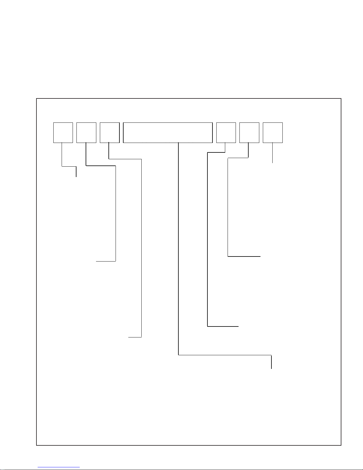
Cooking Nomenclature
J E S 9 8 6 0 B A W
Color
A Almond on Almond
Brand
A Amana
C Magic Chef
G Graffer &
Sattler
H Hardwick
J Jenn-Air
M Maytag
N Norge
U Universal
Y Crosley
Fuel
B Butane
D Dual Fuel
E/J Electric
G Gas, Natural
L Liquid Propane
M Microwave
P Standing Pilot
X No Fuel
W Warming Drawer
Product Type
A Accessory/Cartridge
C Cooktop Updraft/Countertop
D Downdraft Cooktop or Warming Drawer
E Eyelevel Range
G Grill
L Range (20")
M Range (36")
P Drop In (24")
Q Wall Oven (27")
R Range, Free-Standing (30")
S Slide-In (30")
T Range Hood
V OTR
W Wall Oven
Y RV Range
Z RV Top
© 2006 Maytag Services 16026926 7
B Black
C Brushed Chrome
H Traditional White
L Traditional Almond
P Prostyle
Q Monochromatic Bisque
S Stainless
T Traditional Bisque
W White on White
F Frost White (True Color White)
N Natural Bisque (True Color Bisque)
Listing
A UL/AGA
C CSA/CGA/CUL
D Dual Listed
G 220-240 V / 50-60 Hz
M Military Model
P PSB Approved
(Singapore)
X Export 120 V / 60 Hz
Productio n Code
This identifies the
production version.
Feature Content
1000-3999 Brands
4000-6999 Maytag/Amana
7000-9999 Jenn Air

General Information
Specifications
Refer to individual Technical Sheet for specification
information.
Placement of the Oven
This freestanding range must be placed in the kitchen or
comparable room. All safety guidelines must be followed
and free air flow around the range is essential.
Do Not Block Air Vents
All air vents must be kept clear during cooking. If air
vents are covered during operation, the oven may
overheat. If this occurs, a sensitive, thermal safety device
automatically removes power to the oven, rendering the
oven inoperable. The oven will remain in this state until it
has sufficiently cooled.
Location of Model Number
To request service information or replacement parts, the
service center will require the complete model, serial, and
manufacturing number of your slide-in range. The
number can be found on the oven chassis behind the
front Access Panel or behind the Warming Drawer along
the front frame. Remove the front Access Panel or pull
out the Warming Drawer to view the data.
Model Number
Access Panel
For a permanently connected appliance: This
appliancemust be connected to a grounded, metallic,
permanent wiring system, or an equipment grounding
conductor should be run with the circuit conductors and
connected to the equipment grounding terminal or lead
on the appliance.
Model Identification
Complete enclosed registration card and promptly return.
If registration card is missing:
• For Jenn-Air product call 1-800-536-6247 or visit the
Web Site at www.jennair.com
• For Maytag product call 1-800-688-9900 or visit the
Web Site at www.jennair.com
• For Amana product call 1-800-843-0304 or visit the
Web Site at www.jennair.com
• For product inCanada call 1-800-688-2002.
When contacting provide product information located on
rating plate. Record the following:
Model Number: ___________________
Manufacturing Number: ___________________
Serial or S/N Number: ___________________
Date of purchase: ___________________
Dealer’s name and address: ___________________
Service
Keep a copy of sales receipt for future reference or in
case warranty service is required. To locate an authorized
servicer:
• For Jenn-Air/Maytag product call 1-800-462-9824 or
visit the Web Sites at www.jennair.com or
www.maytag.com
• For Amana product call 1-800-628-5782 or visit the
Web Site at www.amana.com
• For product inCanada call 1-800-688-2002.
Warranty service must be performed by an authorized
servicer. We also recommend contacting an authorized
servicer, if service is required after warranty expires.
Grounding Instructions
This appliance must be grounded. If an electrical short
circuit occurs, grounding reduces the risk of electric
shock by providing an escape wire for the electric current.
The cord for this appliance has a grounding wire with a
grounding plug. Put the plug into an outlet that is properly
installed and grounded.
WARNING
!
To avoid risk of electric shock, personal injury or death,
use grounding plug properly.
Ask a qualified electrician if you do not understand the
grounding instructions or if you have questions when
grounding the appliance. Keep the electrical power cord
dry and keep it from getting crushed or pinched.
8 16026926 © 2006 Maytag Services
Parts and Accessories
Purchase replacement parts and accessories over the
phone. To order accessories for your product call:
• For Jenn-Air product call 1-800-536-6247 or visit the
Web Site at www.jennair.com
• For Maytag product call 1-800-688-9900 or visit the
Web Site at www.jennair.com
• For Amana product call 1-800-843-0304 or visit the
Web Site at www.jennair.com
• For product inCanada call 1-800-688-2002.
Extended Service Plan
We offer long-term service protection for this new oven.
• Asure™ Extended Service Plan is specially designed
to supplement Maytag and Amana’s strong warranties.
These plans cover parts, labor, and travel charges.
Call 1-866-232-6244 for information.
• Dependability PlusSM Extended Service Plan is
specially designed to supplement Jenn-Air’s strong
warranty. This plan covers parts, labor, and travel
charges. Call 1-800-925-2020 for information.

Range Description
Range Description
Cooking Surface
Downdraft Vent
Infinite Switches
Electronic Controls
Oven Cavity:
Broil Element
Convection Element
Bake Element
Convection Fan
Baking Racks
Temperature Probe
Access Panel:
Model Number
Rating Label
© 2006 Maytag Services 16026926 9
Troubleshooting Procedures
!
To avoid risk of electrical shock, personal injury, or death, disconnect power to range before servicing, unless
testing requires power.
WARNING
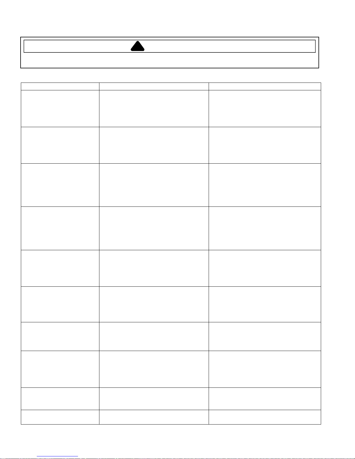
Troubleshooting Chart
Problem Possible Cause Correction
Open bake element ..................................
No bake element operation
No broil element operation
Oven not operating
Clock and timer not working
Oven light does not operate
Oven door will not unlock
Oven smokes/odor first few
times of usage
Surface element doesn’t
heat
Self-clean cycle not working Programming error....................................
Frequent cycling of surface
element or warming zone
Loose wire connection or broken wire ......
Open bake relay .......................................
Open broil element ...................................
Loose wire connection or broken wire ......
Open broil relay ........................................
Programming error....................................
Power outage............................................
Unit in Sabbath mode ...............................
Power outage............................................
Electronic Control locked..........................
Failed oven lamp ......................................
Failed wiring..............................................
Failed light socket .....................................
Oven is self-cleaning ................................
Oven is still hot .........................................
Normal ......................................................
Open element ...........................................
Loose wire connection or broken wire ......
Failed infinite switch..................................
Door lock...................................................
Normal ......................................................
• Check element for continuity, replace if
failed.
• Verify all connections are clean and
tight, replace broken wire.
• Verify 240 VAC at bake element.
• Check element for continuity, replace if
failed.
• Verify all connections are clean and
tight, replace broken wire.
• Verify 240 VAC at broil element.
• Switch circuit breaker off to oven for
five minutes and try oven again.
• Verify power is present at unit and
circuit breaker is not tripped.
• Refer to Use & Care manual and
remove unit from Sabbath mode.
• Verify power is present at unit and
circuit breaker is not tripped.
• Replace household fuse, but do not
fuse capacity.
• Refer to Use and Care manual and
unlock electronic control.
• Check lamp and replace is necessary.
• Check for broken, loose or dirty
connections.
• Check light socket for continuity.
• Allow cycle to complete.
• Will not unlock until unit has cooled to
safe temperature. Do not force door
open, this will void warranty. Blow cool
air on door latch to quicken process.
• Minor smoking or odor is normal the
first few times of oven usage.
• Ventilate area well and perform selfclean cycle.
• Check element for continuity, replace if
failed.
• Verify all connections are clean and
tight, replace broken wiring.
• Check infinite switch, replace if failed.
• Turn off circuit breaker for five minutes
and try oven again.
• Verify door lock energizes & engages.
• Element cycles to maintain proper heat
and to prevent damage to smoothtop.
10 16026926
© 2006 Maytag Services
Troubleshooting Procedures
!
WARNING
To avoid risk of electrical shock, personal injury, or death, disconnect power to range before servicing, unless
testing requires power.
Description of Fault Codes for EOC III
Each fault code consists of 4 digits and is structured as follows:
1st (Leftmost) Digit:
Primary Failure System
1 – Local to Control System d – Diagnostic Failure (measurable)
3 – Sensor or Meat Probe c – Control-Related Error (not measurable)
4 – Input to Control System
9 – Door Lock
2nd Digit: Alpha-Character 3rd Digit: Secondary
Failure Mechanism
4th Digit : Oven
Cavity Number
1 – Upper (Single) Oven
2 – Lower Oven
c – Control System
If a fault is detected, then one of the following three messages will be scrolled on the display:
FAULT DETECTED PRESS ENTER TO TRY AGAIN. This message displays when a fault is detected while a
cooking function is active. Clear by pressing the Cancel keypad.
FEATURE NOT AVAILABLE. This message displays when a fault is detected while entering data during initial
programming and also when a locked out function is detected. Clear by pressing any key.
FAULT DETECTED DISABLE POWER TO CLEAR. This message displays when a runaway temperature condition
is detected while the control is in idle mode. Press any key to clear the message, but the fault remains until the
control senses a Power-On reset.
Fault Code Chart
Fault
Code
1c1c Shorted key.
1c2c Membrane keyboard disconnected.
1c4c Board – to – Board communication failure. Replace control.
1c6c EEPROM hardware fault. Replace control.
1c7c Control not calibrated. Replace control.
1c8c EEPROM CRC error – User Options. Replace control.
1c81 EEPROM CRC error – Cook Profile. Replace control.
1d11 Unlocked runaway temperature – 600° F
1d21 Locked runaway temperature – 950° F
3d11 Temperature sensor open.
3d21 Temperature sensor shorted.
3d41 Meat probe shorted.
3d51 Meat probe not calibrated.
4d11 Door switch not closed when locked. Check connections, switch, harness, and motor. If OK, replace control.
4d21 No cooling fan rotation. Check cooling fan motor and harness. If OK, replace control.
4d31 Cooling fan on when de-energized. Check cooling fan motor and harness. If OK, replace control.
4d41 Cooling fan overspeed. Check cooling fan motor and harness. If OK, replace control.
4d51 Door switch circuit fault. Check connections, harness, and motor. If OK, replace control.
9d11 Latch will not lock. Check wire connections. If OK, replace motorized door lock.
9d21 Latch will not unlock. Check wire connections. If OK, replace motorized door lock.
9d31 Latch both locked and unlocked. Check wire connections. If OK, replace motorized door lock.
Description Component to Troubleshoot/Replace
Ensure ribbon cable is securely connected, inspect ribbon cable and
connector (shorts, breakage, corrosion, etc.). If OK, replace control.
Ensure ribbon cable is securely connected, inspect ribbon cable and
connector (shorts, breakage, corrosion, etc.). If OK, replace control.
Ohm sensor and harness (see "Oven Sensor" chart). If OK, change
control.
Ohm sensor and harness (see "Oven Sensor" chart). If OK, change
control.
Check connections, sensor (see "Oven Sensor" chart) and harness. If
OK, replace control.
Check connections, sensor (see "Oven Sensor" chart) and harness. If
OK, replace control.
Check probe jack and harness. If OK, check meat probe (see "Meat
Probe" chart).
Check probe jack and harness. If OK, check meat probe (see "Meat
Probe" chart).
© 2006 Maytag Services 16026926 11
Troubleshooting Procedures
!
To avoid risk of electrical shock, personal injury, or death, disconnect power to range before servicing, unless
testing requires power.
WARNING
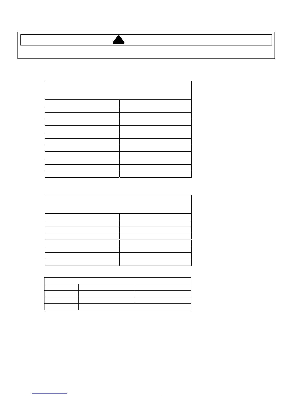
Oven Sensor, Meat Probe and Cooling Fan Temperature Charts
Sensor Type: RTD 1000 Ω platinum
Calibration: 1654 Ω (350° F / 177° C)
Temperature F (C) Resistance (Ohms)
100 (38) 1143
200 (94) 1350
300 (149) 1553
350 (177) 1654
400 (204) 1753
500 (260) 1949
600 (316) 2142
700 (371) 2331
800 (427) 2516
900 (483) 2697
1000 (538) 2874
Type: NTC Thermistor
Calibration: 9938 Ω (150° F / 65.5° C)
Temperature F (C) Resistance (Ohms)
32 (0) 163300
68 (20) 62450
95 (35) 32660
122 (50) 18020
158 (70) 8760
185 (85) 5360
212 (100) 3400
MODE FAN ON TEMP F (C) FAN OFF TEMP F (C)
Bake 300 (148.9) 275 (135)
Broil Immediately 275 (135)
Clean Immediately 275 (135)
COOLING FAN TEMPERATURES
OVEN SENSOR
MEAT PROBE
12 16026926
© 2006 Maytag Services
Testing Procedures
.
.
O
.
.
.
.
.
.
.
.
.
.
.
.
.
.
.
.
.
.
.
.
.
.
.
.
.
!
WARNING
To avoid risk of electrical shock, personal injury, or death, disconnect power to range before servicing, unless
testing requires power.
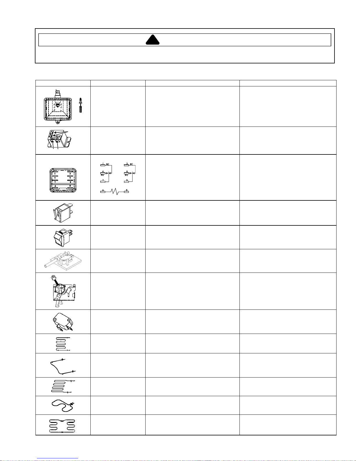
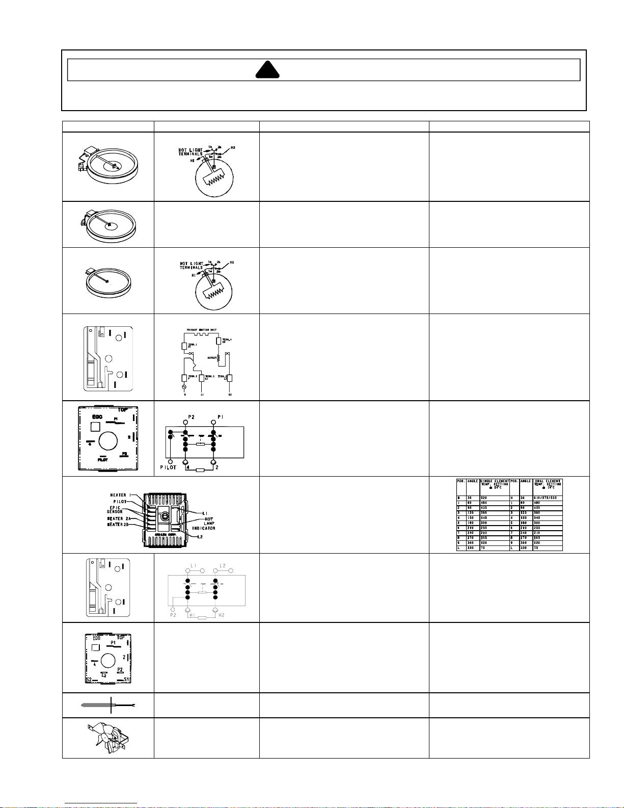
Component Testing Procedures
Illustration Component Test Procedure Results
COM N
(JES8850BC*,
JES9900BC*)
Coil
Ter mi n al s
C
N
O
O
M
Oven light & housing Disconnect connector and test
resistance of terminals.............................
Measure voltage at oven light..................
Remote relay Infinite switch in the following positions:
On (any setting) ...................................
Off........................................................
Top power relay
Power applied:
Pins 1 (NC) and 7 ................................
Pins 3 (NC) and 9 ................................
Power not applied:
Pins 1 (NC) and 4 (NO) ........................
Pins 3 (NC) and 6 (NO) ........................
Pins A to B...............................................
Indicator lights Measure voltage at indicator light ............
Rocker switch Measure continuity of switch positions:
Open....................................................
Closed..................................................
Door plunger switch Remove switch from unit and measure
the following points:
Door closed..........................................
Door open............................................
Autolatch assembly Disconnect wires and test for continuity
per wiring diagram ...................................
Refer to Parts Manual for correct
autolatch switch associated with the
correct manufacturing number.
Door lock switch Switch connection in the following
positions:
Door latch locked.................................
Door latch unlocked .............................
Hidden bake element Disconnect wiring to element and
measure cold resistance of terminals ......
Measure voltage at bake element............
Bake element Disconnect wiring to element and
measure cold resistance of terminals ......
Measure voltage at bake element............
Broil element Disconnect wiring to element and
measure cold resistance of terminals ......
Measure voltage at broil element.............
Warmer element Disconnect wiring to element and
measure cold resistance of terminals ......
Measure voltage at broil element.............
Convection element Disconnect wiring to element and
measure cold resistance of terminals ......
Measure voltage at convect element.......
Verify bulb is properly inserted.
Continuity with bulb inserted.
120 VAC, see wiring diagram for terminal
identification.
If voltage is not present at oven light,
check wiring or light switches.
COM-NO= Continuity (closed).
COM-NO= Infinity (open).
Continuity.
Continuity.
Continuity.
Continuity.
24 VDC when power applied.
If voltage is present and light does not
work, replace light.
If voltage is not present at indicator light,
check wiring.
Infinite.
Continuity.
COM-NO= Continuity (closed).
COM-NO= Infinity (open).
See wiring diagram for schematic layout.
Common is in neutral position unless
locking or unlocking autolatch assembly.
COM-NO= Continuity (closed).
COM-NO= Infinity (open).
Approx. 20 .
240 VAC.
Approx. 22 .
240 VAC.
Approx. 12.5 to 18 .
240 VAC.
Approx. 12.5 to 18 .
120 VAC.
Approx. 16.5 .
240 VAC.
© 2006 Maytag Services 16026926 13
Testing Procedures
!
WARNING
To avoid risk of electrical shock, personal injury or death; disconnect power to range before servicing, unless
testing requires power.
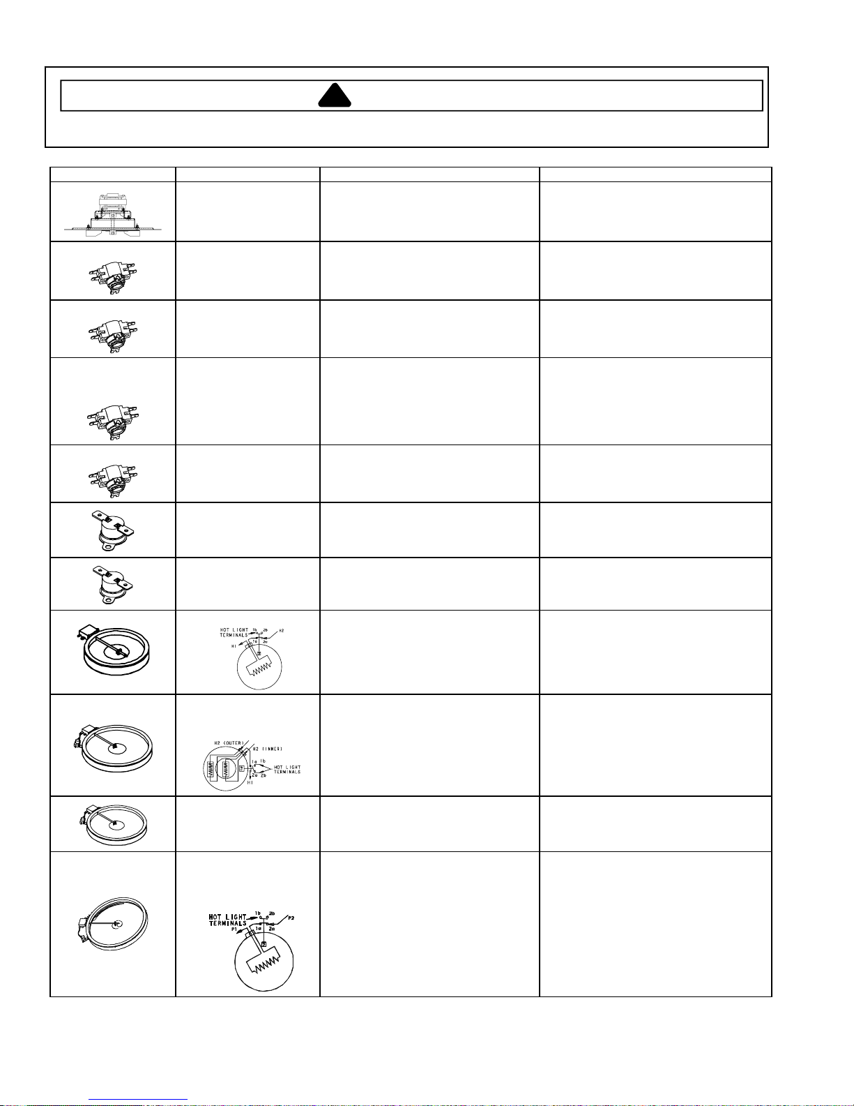
Illustration Component Test Procedure Results
(JES8750BA*)
(JES8850B**)
(JES9860B**,
JES9800BA*,
JES9900B**)
(JES9750BA*)
Convection motor,
2-speed
Oven limit switch Normally closed, verify operation:
Oven limit switch Normally closed, verify operation:
Oven limit switch Normally closed, verify operation:
Oven limit switch Normally closed, verify operation:
Hi-limit temperature
switch
(Warming Drawer)
Hi-limit temperature
switch
(Warming Drawer)
Ribbon element, 1200 W
Measure voltage ....................................
Check motor windings to ground............
Open: 208° to 222° F (98° to 105° C) ...
Closed: 156° to 174° F (69° to 79° C) ..
Open: 130° to 140° F (54° to 60° C).......
Closed: 109° to 121° F (43° to 50° C) ....
Open: 209° to 221° F (98° to 105° C).....
Closed: 144° to 166° F (62° to 74° C) ....
Open: 208° to 222° F (98° to 105° C).....
Closed: 156° to 174° F (69° to 79° C) ....
Normally closed, verify operation:
Open: 135° to 145° F (57° to 63° C).....
Closed: 114° to 126° F (46° to 52° C) ..
Normally closed, verify operation:
Open: 95° to 105° F (35° to 41° C).......
Closed: 79° to 91° F (26° to 33° C)......
Disconnect wiring to element and
measure cold resistance of terminals.....
Measure voltage at element ...................
120 VAC. (tolerance: 105 to 135 VAC).
No continuity.
RPM, Lo-speed: Approx. 1440 to 2040.
RPM, Hi-speed: Approx. 1860 to 2460.
Infinite.
Continuity.
Infinite.
Continuity.
Infinite.
Continuity.
Infinite.
Continuity.
Infinite.
Continuity.
Infinite.
Continuity.
Approx. 44 to 49 .
240 VAC.
Ribbon element, Dual,
2400 W (1200 W inner,
1200 W outer)
Ribbon element, Dual,
3000 W (1400 W inner,
1600 W outer)
Ribbon element, Triple,
3000 W (1000 W inner,
2000 W middle
2700 W outer)
14 16026926 © 2006 Maytag Services
Disconnect wiring to element and
measure cold resistance of terminals.....
Measure voltage at element ...................
Disconnect wiring to element and
measure cold resistance of terminals.....
Measure voltage at element ...................
Disconnect wiring to element and
measure cold resistance of terminals.....
Measure voltage at element ...................
Inner: Approx. 44 to 49 .
Outer: Approx. 44 to 49 .
240 VAC.
Inner: Approx. 38 to 42 .
Outer: Approx. 34 to 37 .
240 VAC.
Inner: Approx. 52 to 57 .
Middle: Approx. 25 to 29 .
Outer: Approx. 19 to 24 .
240 VAC.
Testing Procedures
.
.
.
.
.
.
.
.
.
.
.
.
.
.
.
.
.
.
!
WARNING
To avoid risk of electrical shock, personal injury, or death, disconnect power to range before servicing, unless
testing requires power.
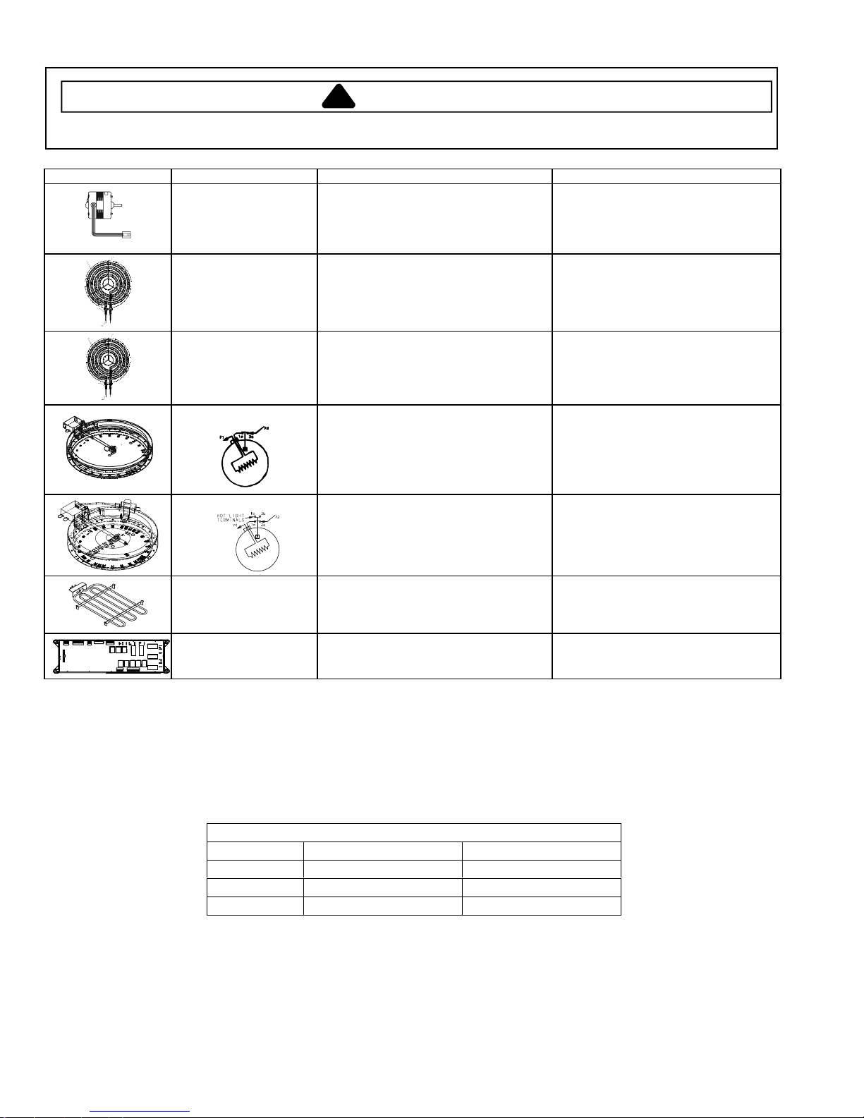
Illustration Component Test Procedure Results
Ribbon element,100 W
Ribbon element, Dual,
3000 W (1400 W inner,
1600 W outer)
Ribbon element, 2500 W
5
L1
3
L2
H2
4
P
2
1
H1
Infinite switch, low heat
Infinite switch
Infinite switch, custom control
Disconnect wiring to element and
measure cold resistance of terminals. .......
Measure voltage at element ......................
Disconnect wiring to element and
measure cold resistance of terminals. .......
Measure voltage at element ......................
Disconnect wiring to element and
measure cold resistance of terminals. .......
Measure voltage at element ......................
Remove wiring from H1 and H2. Connect
volt/ohms meter to H1 and H2.
Measure the following for voltages at LO,
MED, HI:....................................................
Voltage between H1 and H2 ......................
Remove wiring from P1 and P2. Connect
volt/ohms meter to P1 and P2. Measure
the following for voltages at LO, MED,
HI:..............................................................
Voltage between P1 and P2 ......................
Single/dual element temp settings.............
Voltage between L1 and L2 ...... 240 VAC.
Approx. 133 to 147 .
120 VAC.
Inner: Approx. 38 to 42 .
Outer: Approx. 34 to 37 .
240 VAC.
Approx. 21 to 24 .
240 VAC.
Approximate
Time On Time Off
SIMMER 5% 95%
MED (5) 55% 45%
HI 100% 0%
240 VAC.
Approximate
Time On Time Off
SIMMER 5% 95%
MED (5) 35% 65%
HI 100% 0%
240 VAC.
5
L1
3
L2
H2
4
P
2
1
H1
Infinite switch
Dual element infinite
switch
Temperature sensor Measure resistance ...................................
Cooling fan motor Measure voltage........................................
© 2006 Maytag Services 16026926 15
Remove wiring from H1 and H2. Connect
volt/ohms meter to H1 and H2. Measure
the following for voltages at LO, MED, HI: .
Voltage between H1 and H2 ......................
Time On Time Off
SIMMER 5% 95%
MED (5) 35% 65%
HI 100% 0%
240 VAC.
Approximate
Remove wiring from S1 and S2.
Connect volt/ohms meter to S1 and S2
and measure voltages at LO, MED, HI ......
Voltage between S1 and S2 ......................
Time On Time Off
SIMMER 5% 95%
MED (5) 45% 55%
HI 100% 0%
240 VAC.
Approximate
Approx. 1000 at room temperature,
75° F (23.8° C).
120 VAC.
Check motor windings to ground ...............
No continuity.
RPM: Approx. 1670 to 2070.
Testing Procedures
!
WARNING
To avoid risk of electrical shock, personal injury or death; disconnect power to range before servicing, unless
testing requires power.
Illustration Component Test Procedure Results
`
Downdraft motor
NOTE: Downdraft fan
will not engage if pan
(snap) switch is not
activated.
Coil element,
1250 W, 4-turn
Coil element,
2100 W, 5-turn
Ribbon element, 1800 W
Ribbon element, 1200 W
Grill assembly Disconnect wiring to element and
Electronic control NOTE: To avoid equipment damage,
Measure voltage ........................................
Check motor windings to ground................
Disconnect wiring to element and
measure cold resistance of terminals.........
Measure voltage at element.......................
Cartridge JEA7000AD*
Disconnect wiring to element and
measure cold resistance of terminals.........
Measure voltage at element.......................
Cartridge JEA7000AD*
Disconnect wiring to element and
measure cold resistance of terminals.........
Measure voltage at element.......................
Cartridge JEA8120AD*
Disconnect wiring to element and
measure cold resistance of terminals.........
Measure voltage at element.......................
Cartridge JEA8120AD*
measure cold resistance of terminals.........
Measure voltage at grill element ................
use caution when checking electronic
control circuitry voltages.
120 VAC.
No continuity.
RPM: 1550
Approx. 42 to 48 .
240 VAC
Approx. 25 to 28 .
240 VAC
Approx. 29.5 to 33.5 .
240 VAC
Approx. 44.5 to 48.5 .
240 VAC
Approx. 30 .
240 VAC.
Cooling Fan Temperatures
MODE FAN ON TEMP F (C) FAN OFF TEMP F (C)
Bake 300 (148.9) 275 (135)
Broil Immediately 275 (135)
Clean Immediately 275 (135)
COOLING FAN TEMPERATURES
16 16026926 © 2006 Maytag Services
Testing Procedures
!
WARNING
To avoid risk of electrical shock, personal injury, or death, disconnect power to range before servicing, unless
testing requires power.
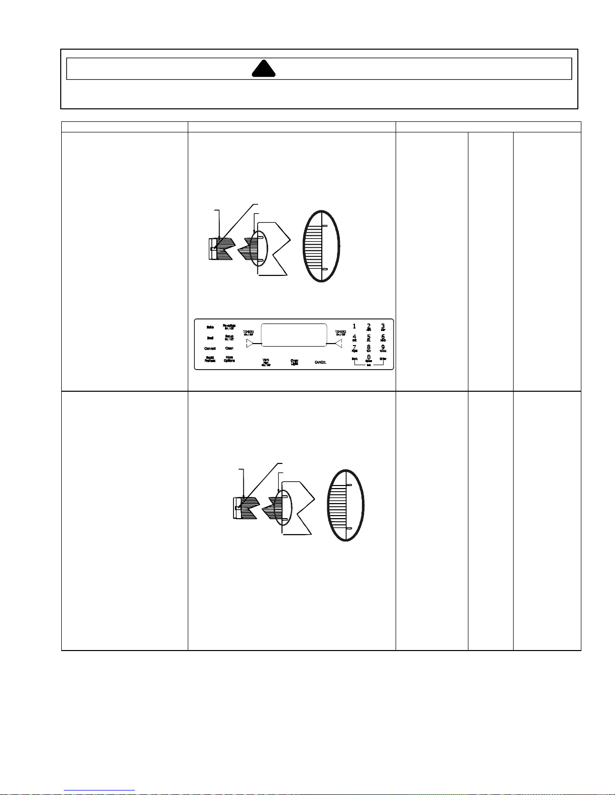
Control Testing Procedures
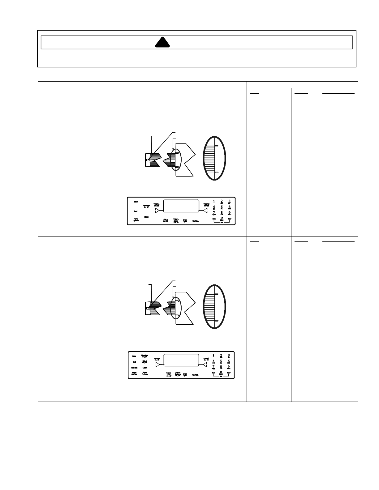
Switch Membrane Assembly Test Procedure Resul ts
Pad
1
2
3
4
5
6
7
8
9
0
Cancel
Bake
Broil
Clean
Favorites
More Options
Warm Zone
Setup
ATM 1
ATM 2
Back
Enter
Timer 1
Timer 2
Oven Light
Pad
1
2
3
4
5
6
7
8
9
0
Cancel
Bake
Broil
Convect
Clean
Favorites
Rapid Preheat
Warm Drawer
Warm Zone
More Options
Setup
ATM 1
ATM 2
Back
Enter
Timer 1
Timer 2
Oven Light
JES8750BA*
JES8850BA*
Closed circuitry resistance
(defined as continuity): 2000 Max
Pins 1 & 6 are shorted together for control
configuration purposes
Trace # 1
Latch
See Detail B
Detail B
Closed circuitry resistance
(defined as continuity): 2000 Max
Pins 1 & 9 are shorted together for control
configuration purposes
Trace # 1
Latch
See Detail B
Detail B
Trace
2 & 7
2 & 8
2 & 9
2 & 10
2 & 11
2 & 12
3 & 6
3 & 7
3 & 8
2 & 6
4 & 9
4 & 10
4 & 11
5 & 7
4 & 12
5 & 8
5 & 12
5 & 6
4 & 6
4 & 7
3 & 9
3 & 10
3 & 11
3 & 12
4 & 8
Trace
2 & 7
2 & 8
2 & 9
2 & 10
2 & 11
2 & 12
3 & 6
3 & 7
3 & 8
2 & 6
4 & 9
4 & 10
4 & 11
5 & 9
5 & 7
4 & 12
5 & 10
5 & 11
5 & 12
5 & 8
5 & 6
4 & 6
4 & 7
3 & 9
3 & 10
3 & 11
3 & 12
4 & 8
Measurement
Continuity
Continuity
Continuity
Continuity
Continuity
Continuity
Continuity
Continuity
Continuity
Continuity
Continuity
Continuity
Continuity
Continuity
Continuity
Continuity
Continuity
Continuity
Continuity
Continuity
Continuity
Continuity
Continuity
Continuity
Continuity
Measurement
Continuity
Continuity
Continuity
Continuity
Continuity
Continuity
Continuity
Continuity
Continuity
Continuity
Continuity
Continuity
Continuity
Continuity
Continuity
Continuity
Continuity
Continuity
Continuity
Continuity
Continuity
Continuity
Continuity
Continuity
Continuity
Continuity
Continuity
Continuity
© 2006 Maytag Services 16026926 17
Testing Procedures
!
WARNING
To avoid risk of electrical shock, personal injury or death; disconnect power range before servicing, unless testing
requires power.
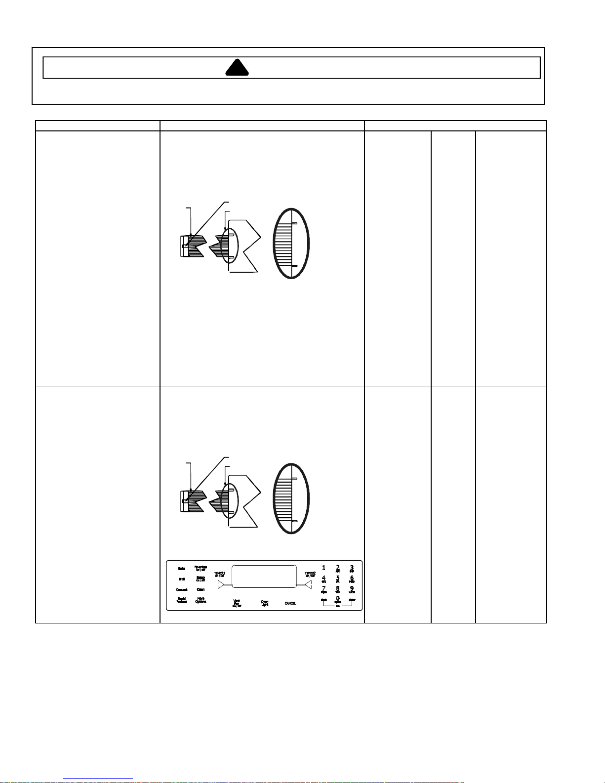
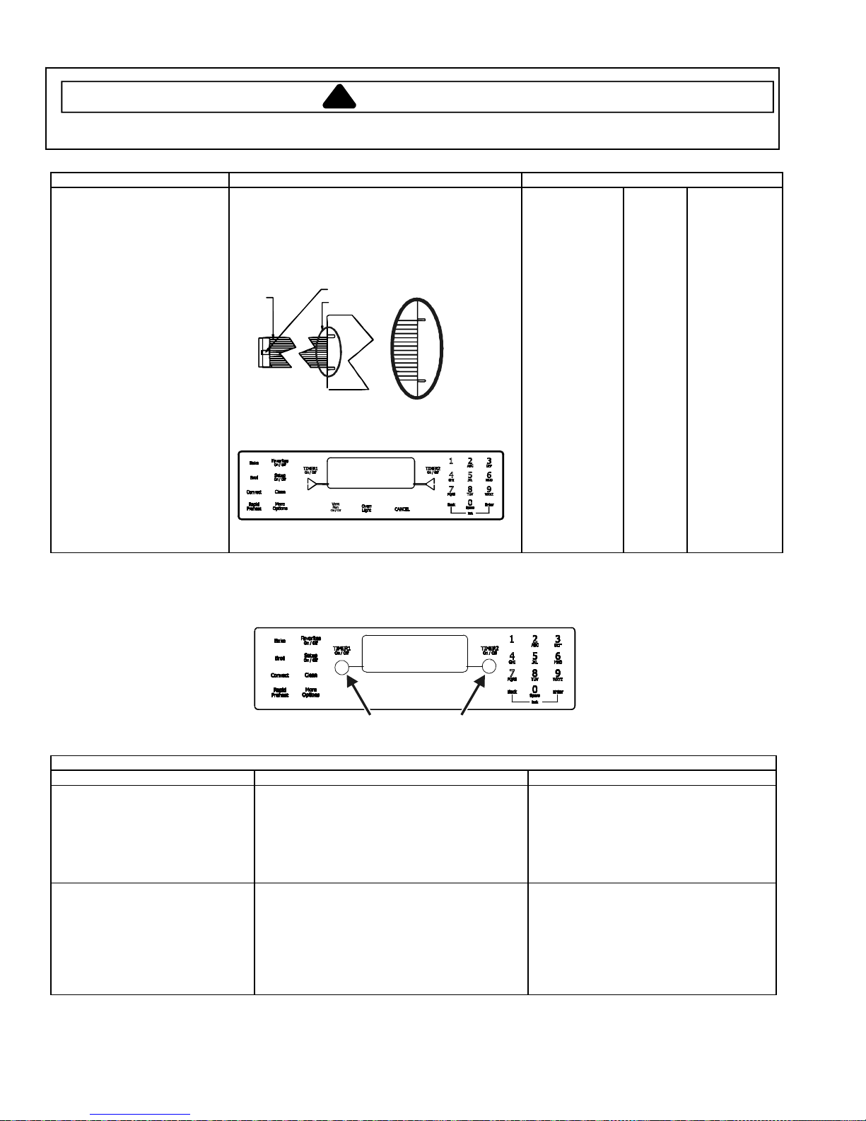
Switch Membrane Assembly Test Procedure Results
JES8850BC*
JES9750BA*
Closed circuitry resistance
(defined as continuity): 2000 Max
Pins 1 & 9 are shorted together for control
configuration purposes
Trace # 1
Latch
See Detail B
Detail B
Closed circuitry resistance
(defined as continuity): 2000 Max
Pins 1 & 11 are shorted together for control
configuration purposes
Trace # 1
Latch
See Detail B
Detail B
Pad
1
2
3
4
5
6
7
8
9
0
Cancel
Bake
Broil
Convect
Clean
Favorites
Rapid Preheat
Warm Zone
More Options
Setup
ATM 1
ATM 2
Back
Enter
Timer 1
Timer 2
Oven Light
Pad
1
2
3
4
5
6
7
8
9
0
Cancel
Bake
Broil
Clean
Favorites
Vent Fan
More Options
Setup
ATM 1
ATM 2
Back
Enter
Timer 1
Timer 2
Oven Light
Trace
2 & 7
2 & 8
2 & 9
2 & 10
2 & 11
2 & 12
3 & 6
3 & 7
3 & 8
2 & 6
4 & 9
4 & 10
4 & 11
5 & 9
5 & 7
4 & 12
5 & 10
5 & 12
5 & 8
5 & 6
4 & 6
4 & 7
3 & 9
3 & 10
3 & 11
3 & 12
4 & 8
Trace
2 & 7
2 & 8
2 & 9
2 & 10
2 & 11
2 & 12
3 & 6
3 & 7
3 & 8
2 & 6
4 & 9
4 & 10
4 & 11
5 & 7
4 & 12
5 & 11
5 & 8
5 & 6
4 & 6
4 & 7
3 & 9
3 & 10
3 & 11
3 & 12
4 & 8
Measurement
Continuity
Continuity
Continuity
Continuity
Continuity
Continuity
Continuity
Continuity
Continuity
Continuity
Continuity
Continuity
Continuity
Continuity
Continuity
Continuity
Continuity
Continuity
Continuity
Continuity
Continuity
Continuity
Continuity
Continuity
Continuity
Continuity
Continuity
Measurement
Continuity
Continuity
Continuity
Continuity
Continuity
Continuity
Continuity
Continuity
Continuity
Continuity
Continuity
Continuity
Continuity
Continuity
Continuity
Continuity
Continuity
Continuity
Continuity
Continuity
Continuity
Continuity
Continuity
Continuity
Continuity
18 16026926 © 2006 Maytag Services
Testing Procedures
!
WARNING
To avoid risk of electrical shock, personal injury, or death, disconnect power to range before servicing, unless
testing requires power.
Switch Membrane Assembly Test Procedure Results
JES9860BA*
JES9860BC*
JES9900BC*
Closed circuitry resistance
(defined as continuity): 2000 Max
Pins 1 & 10 are shorted together for control
configuration purposes
Trace # 1
Latch
See Detail B
Detail B
Closed circuitry resistance
(defined as continuity): 2000 Max
Pins 1 & 10 are shorted together for control
configuration purposes
Trace # 1
Latch
See Detail B
Detail B
Pad
1
2
3
4
5
6
7
8
9
0
Cancel
Bake
Broil
Convect
Clean
Favorites
Rapid Preheat
Vent Fan
More Options
Setup
ATM 1
ATM 2
Back
Enter
Timer 1
Timer 2
Oven Light
Pad
1
2
3
4
5
6
7
8
9
0
Cancel
Bake
Broil
Convect
Clean
Favorites
Rapid Preheat
Vent Fan
More Options
Setup
ATM 1
ATM 2
Back
Enter
Timer 1
Timer 2
Oven Light
Trace
2 & 7
2 & 8
2 & 9
2 & 10
2 & 11
2 & 12
3 & 6
3 & 7
3 & 8
2 & 6
4 & 9
4 & 10
4 & 11
5 & 9
5 & 7
4 & 12
5 & 10
5 & 11
5 & 8
5 & 6
4 & 6
4 & 7
3 & 9
3 & 10
3 & 11
3 & 12
4 & 8
Trace
2 & 7
2 & 8
2 & 9
2 & 10
2 & 11
2 & 12
3 & 6
3 & 7
3 & 8
2 & 6
4 & 9
4 & 10
4 & 11
5 & 9
5 & 7
4 & 12
5 & 10
5 & 11
5 & 8
5 & 6
4 & 6
4 & 7
3 & 9
3 & 10
3 & 11
3 & 12
4 & 8
Measurement
Continuity
Continuity
Continuity
Continuity
Continuity
Continuity
Continuity
Continuity
Continuity
Continuity
Continuity
Continuity
Continuity
Continuity
Continuity
Continuity
Continuity
Continuity
Continuity
Continuity
Continuity
Continuity
Continuity
Continuity
Continuity
Continuity
Continuity
© 2006 Maytag Services 16026926 19
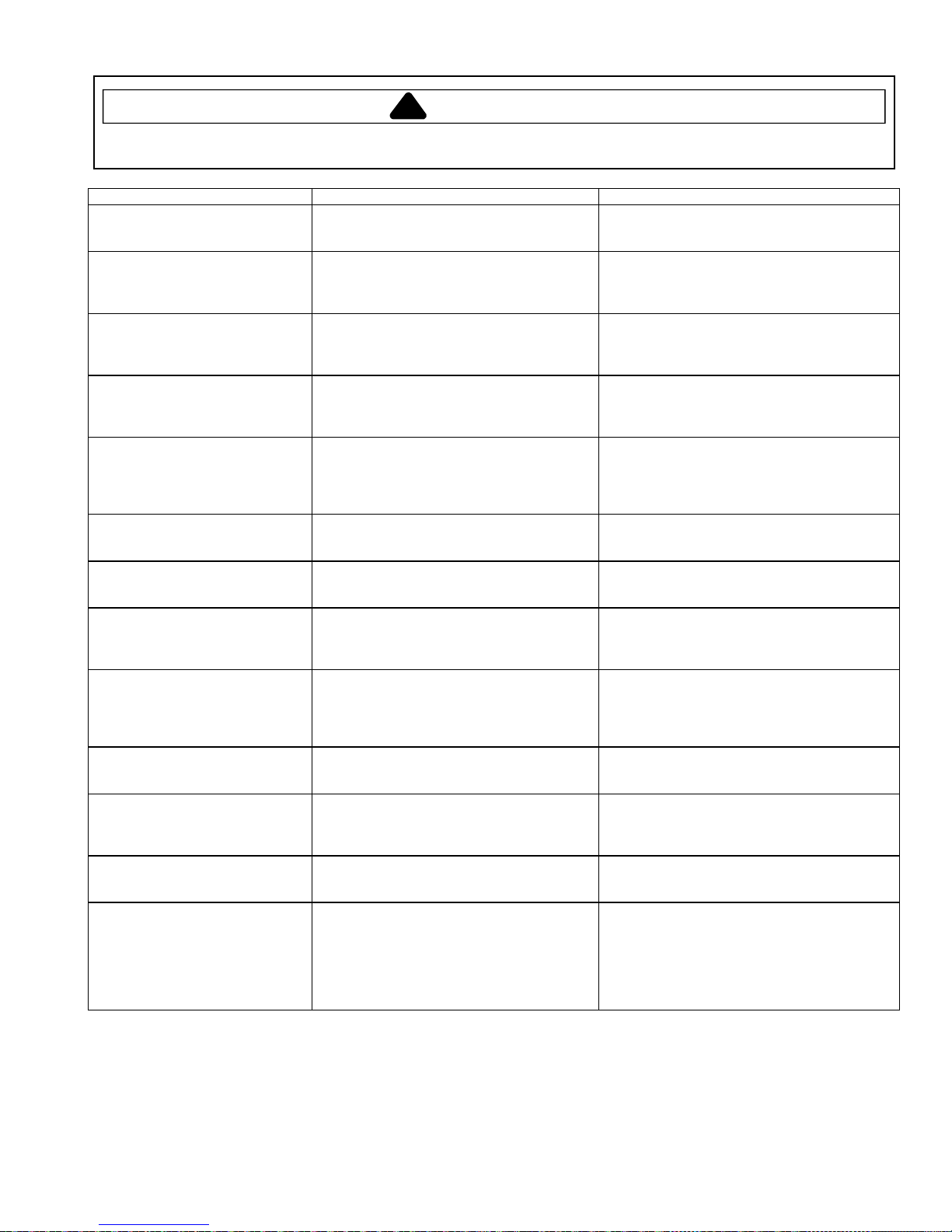
Testing Procedures
!
WARNING
To avoid risk of electrical shock, personal injury or death; disconnect power range before servicing, unless testing
requires power.
Switch Membrane Assembly Test Procedure Results
JES9800BA*,
JES9900BA*
Closed circuitry resistance
(defined as continuity): 2000 Max
Pins 1 & 10 are shorted together for control
configuration purposes
Trace # 1
Latch
See Detail B
Detail B
Pad
1
2
3
4
5
6
7
8
9
0
Cancel
Bake
Broil
Clean
Convect
Favorites
Rapid Preheat
Vent Fan
More Options
Setup
ATM 1
ATM 2
Back
Enter
Timer 1
Timer 2
Oven Light
Trace
2 & 7
2 & 8
2 & 9
2 & 10
2 & 11
2 & 12
3 & 6
3 & 7
3 & 8
2 & 6
4 & 9
4 & 10
4 & 11
5 & 7
5 & 9
4 & 12
5 & 10
5 & 11
5 & 8
5 & 6
4 & 6
4 & 7
3 & 9
3 & 10
3 & 11
3 & 12
4 & 8
Measurement
Continuity
Continuity
Continuity
Continuity
Continuity
Continuity
Continuity
Continuity
Continuity
Continuity
Continuity
Continuity
Continuity
Continuity
Continuity
Continuity
Continuity
Continuity
Continuity
Continuity
Continuity
Continuity
Continuity
Continuity
Continuity
Continuity
Continuity
Electronic Oven Control (EOC) III Testing Procedures
ELECTRONIC OVEN CONTROL III TESTING/PROGRAMMING PROCEDURES
Feature Access Procedure Modification Procedure
Control Reset
Resets control to factory default
values.
Oven Temperature Adjustm ent
Determines oven cavity offset
temperature (range from -35° F to
+35° F, or -21° C to +21° C).
Press the Setup pad, then press the right ATM
pad until SERVICE displays. Press the left
ATM pad to select SERVICE menu options.
Press the Setup pad, then press the right ATM
pad until TEMP ADJUST displays. Press the
left ATM pad to select oven TEMP
ADJUSTMENT settings.
20 16026926 © 2006 Maytag Services
Warm
Drawer
ATM PADS
Press and hold the Back and Enter pads
for 5 seconds to enter SERVICE menu
options. Press the right ATM pad to scroll
to CONTROL RESET. Press the left ATM
pad to select CONTROL RESET, then
press the left ATM pad again to reset the
control logic. Press Setup to exit.
Enter the offset temperature setting desired
using the digits pads. Press the right ATM
pad for + temperature adjustment, or the
left ATM pad for – temperature adjustment.
Press 0 to reset control back to no
temperature adjustment. Wait 3 seconds
for the control to accept the request. Press
Setup to exit.
Testing Procedures
!
WARNING
To avoid risk of electrical shock, personal injury, or death, disconnect power to range before servicing, unless
testing requires power.
Feature Access Procedure Modification Procedure
Time Options
Determines control time, day of
week, 12/24 hour clock.
Time Set
Determines time of day (Monday
through Sunday) to display on
control.
Day of Week
Determines day of week (Monday
thru Sunday) to display on control.
12/24-Hour Clock Display
Determines 12-hour or 24-hour
clock display on control.
Clock & Day Display Disable
Determines if time of day and day
of week will display on control.
Language Display
Determines language display on
control (English, French, Spanish).
C/F (Celsius/Fahrenheit) Display
Determines temperature display on
control (C or F).
Auto Convection
When enabled, reduces the
Convection Bake and Pastry
temperatures by 25° F (-3.9° C).
Sabbath Mode
Based on the Jewish guidelines for
Sabbath/Holiday requirements.
Tone Options
Determines cook tones, timer tones
and volume settings.
12-Hour Shutoff
Disables 12-hour shutoff, allowing
the oven to operate indefinitely.
208/240 V Setting
Determines range operating
voltage (208 or 240 VDC).
Cook Tones
Determines the number and
duration of cook time reminder
chimes.
Press the Setup pad, then the left ATM pad
to select TIME OPTIONS.
Press the Setup pad, then the left ATM pad,
then the left ATM pad again to set the time of
day clock.
Press the Setup pad, then the left ATM pad,
then press the right ATM pad until DAY
displays. Press the left ATM pad to set the
day of the week.
Press the Setup pad, then the left ATM pad,
then press the right ATM pad until 12/24HR
displays. Press the left ATM pad to select
12/24 HR clock.
Press the Setup pad, then press the right
ATM pad until DISABLE displays. Press the
left ATM pad to select DISABLE settings.
Press the Setup pad, then press the right
ATM pad until LANGUAGE displays. Press
the left ATM pad to set LANGUAGE settings.
Press the Setup pad, then press the right
ATM pad until C/F displays. Press the left
ATM pad to select C/F settings.
Press the Setup pad, then press the right
ATM pad until AUTO CONVECT displays.
Press the left ATM pad to select AUTO
CONVECT settings.
Press the Setup pad, then press the right
ATM pad until SABBATH displays. Press the
left ATM pad to select SABBATH settings.
Press the Setup pad, then press the right
ATM pad until TONES displays. Press the
left ATM pad to select TONES options.
Press the Setup pad, then press the right
ATM pad until 12HR SHUTOFF displays.
Press the left ATM pad to select 12-HOUR
SHUTOFF settings.
Press the Setup pad, then press the right
ATM pad until 208/240 displays. Press the
left ATM pad to select 208/240 V settings.
Press the Setup pad, then press the right
ATM pad until TONES displays. Press the
left ATM pad. Press the left ATM pad again
to select COOK TONES settings.
Press the right ATM pad to scroll to the desired
function to modify.
Enter the correct time using the digits pads and
press Enter. Press the left ATM pad to select
AM or the right ATM pad to select PM. Press
Setup to exit.
Press the right ATM pad until the correct day
displays, then press the left ATM pad to select.
Press Setup to exit.
Press the left ATM pad to select 12-hour clock,
or the right ATM pad to select 24-hour clock.
Press Setup to exit.
Press the left ATM pad to select TIME, or the
right ATM pad to scroll to DAY, then press the
left ATM pad. Press the left ATM pad to turn
display on or the right ATM pad to turn display
off. Press Setup to exit.
Press the right ATM pad until the desired
language displays (English, French, Spanish).
Press the left ATM pad. Press Setup to exit.
Press the left ATM pad to select Celsius or the
right ATM pad to select Fahrenheit. Press
Setup to exit.
Press the left ATM pad to turn on auto convect,
or the right ATM pad to turn off auto convect.
Press Setup to exit.
Press the left ATM pad to select Manual
Sabbath mode, or the right ATM pad to select
Auto Sabbath mode. Press the left ATM pad to
turn on Sabbath mode, or the right ATM pad to
turn off Sabbath mode. Press Setup to exit.
Press the right ATM pad to scroll to the desired
tone to modify.
Press the left ATM pad to turn on 12-hour
shutoff, or the right ATM pad to turn off 12-hour
shutoff. Press Setup to exit.
Press the left ATM pad to select 208 VDC, or
the right ATM pad to select 240 VDC. Press
Setup to exit.
Press the left ATM pad to select 1 – 30 (1 chime
every 30 seconds after the initial 4 chimes), or
press the right ATM pad to scroll to 1 – 60 (1
chime every 60 seconds after the initial 4
chimes) or 1 BEEP (no additional chimes after
the initial 4 chimes). Press the left ATM pad to
select the desired setting. Press Setup to exit.
© 2006 Maytag Services 16026926 21
 Loading...