

Page 1
USE AND INSTALLATION INSTRUCTIONS
DUCT FREE DOWNDRAFT FILTER ACCESSORY KIT
INSTRUCTIONS D'UTILISATION ET D’INSTALLATION
SYSTÈME DE FILTRAGE SANS CONDUIT POUR
ÉVACUATION PAR LE BAS
Table of Contents/Table des matières
DOWNDRAFT FILTER SAFETY.....................................................1
INSTALLATION REQUIREMENTS................................................2
Tools and Parts ............................................................................2
Location Requirements................................................................2
INSTALLATION INSTRUCTIONS..................................................3
Install Cooktop in the Cabinet .....................................................3
Prepare the Base Cabinet Bottom...............................................4
Assemble Filter System ...............................................................6
Check Operation .......................................................................... 8
Filter System Care........................................................................8
TROUBLESHOOTING ....................................................................8
SÉCURITÉ DU FILTRE D’ÉVACUATION PAR LE BAS................9
EXIGENCES D’INSTALLATION...................................................10
Outils et pièces...........................................................................10
Exigences d’emplacement.........................................................10
INSTRUCTIONS D’INSTALLATION.............................................11
Installation de la table de cuisson dans le meuble....................11
Préparation du plancher du placard inférieur ............................12
Assemblage du système de filtrage...........................................14
Contrôle du fonctionnement ......................................................16
Entretien du système de filtrage ................................................16
DÉPANNAGE.................................................................................16
DOWNDRAFT FILTER SAFETY
Your safety and the safety of others are very important.
We have provided many important safety messages in this manual and on your appliance. Always read and obey all safety
messages.
This is the safety alert symbol.
This symbol alerts you to potential hazards that can kill or hurt you and others.
All safety messages will follow the safety alert symbol and either the word “DANGER” or “WARNING.”
These words mean:
You can be killed or seriously injured if you don't immediately
DANGER
WARNING
All safety messages will tell you what the potential hazard is, tell you how to reduce the chance of injury, and tell you what can
happen if the instructions are not followed.
IMPORTANT:
Installer: Leave installation instructions with the homeowner.
Homeowner: Keep installation instructions for future reference.
follow instructions.
can be killed or seriously injured if you don't
You
instructions.
follow
IMPORTANT :
Installateur : Remettre les instructions d'installation au propriétaire.
Propriétaire : Conserver les instructions d'installation pour référence ultérieure.
W10254051A
Page 2

IMPORTANT INSTRUCTIONS:
The Duct Free Filter Accessory Kit is designed to filter the air from the downdraft system and ventilate the conditioned air out into the
room through the toe-kick area of the base cabinet. Do not ventilate the air from the downdraft system into the base cabinet, base
cabinet pedestal, crawl space, wall or attic.
The Duct Free Filter cartridge is designed for six (6) months of normal cooking activity. The filter cartridge is not designed to be cleaned
and reused. The filter must be changed as indicated by the TimeStrip
®
. If the filter is not changed as recommended, the downdraft
performance will be reduced.
INSTALLATION REQUIREMENTS
Tools and Parts
Gather the required tools and parts before starting installation.
Read and follow the instructions provided with any tools listed
here.
Too ls ne ed ed
■ Tape measure
■ Framing square
■ Hammer
■ Set punch
■ Pliers
■ Marker or pencil
■ Flat-blade screwdriver
■ Phillips screwdriver
■ Drill
■ ¼" (6.4 mm) drill bit
■ ⁷⁄₆₄" (2.8 mm) drill bit
■ Jigsaw or keyhole saw
■ Masking tape
Parts supplied
■ Flow test card
■ Poster board template
■ Duct free filter housing assembly
■ Flex duct
■ 2 - clamps
■ Duct free filter with Time Strip
■ 4 - mounting screws
®
Location Requirements
The Jenn-Air® Duct Free Filter System accessory is approved for
use with JED3430, JED3536, JED 4430, JED4546, JGD3430, and
JGD3536 series Jenn-Air downdraft products.
The Jenn-Air
be installed in cabinetry that is constructed to meet Kitchen
Cabinet Manufacturers Association (KCMA), requirements for
toe-kick space. At a minimum, KCMA toe-kick requires a depth
dimension of 2½" (6.4 cm) and a height dimension of 3" (7.6 cm)
as shown in the illustration.
The Duct Free Filter
The Jenn-Air
1 Duct Free filter cartridge. The filter included with the kit comes
with a 6 month Time Strip
Time Strip
filter housing.
After the installation is complete, press the button on the Time
®
Strip
®
Strip
has elapsed.
A JDA8000WX replacement filter can be obtained by calling
1-800-JENNAIR (1-800-536-6247) or visiting www.jennair.com.
In Canada, call 1-800-807-6777 or visit www.jennair.ca.
®
Duct Free Filter System accessory is designed to
B
A
®
Duct Free Filter System accessory kit includes
®
sensor will be visible after the filter is installed in the
C
A. Floor
B. 2½" (6.4 cm)
C. 3" (7.6 cm)
®
sensor preinstalled on the filter. The
sensor to activate. Once activated, the window of the Time
sensor will darken along the time line until 6 months time
2
Page 3
INSTALLATION INSTRUCTIONS
E
Install Cooktop in the Cabinet
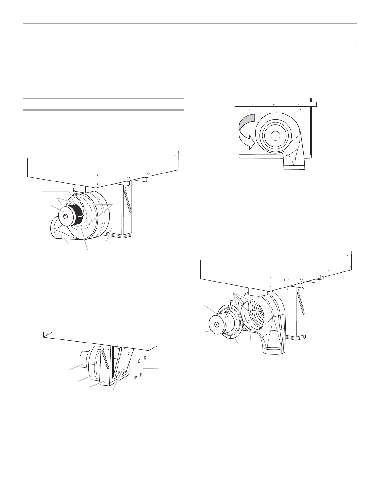
Follow the manufacturer’s recommended instructions for
installing your downdraft cooktop with the downdraft blower
exhaust scroll turned straight down.
To rotate the blower exhaust scroll down, complete the following
steps.
Rotate Blower
IMPORTANT: The following additional steps must be performed
if the cooktop is being installed in a peninsula or island cabinetry.
The blower exhaust scroll is shipped from the factory set to
exhaust straight out the back of the cabinet through an exterior
wall.
D
E
C
A
F
A. Blower exhaust scroll
B. Plenum
C. Blower motor
E
B
D. Top label
E. 10-32 machine nuts (4)
F. Motor mounting plate
3. Insert the ³⁄₈" socket and extension into the hole and use the
ratchet handle to loosen the nut half of a rotation. Repeat this
process for each of the 4 nuts.
4. With the nuts loosened, the blower exhaust scroll can be
easily rotated downward.
5. Retighten each nut with the ³⁄₈" socket, extension and ratchet.
6. Reinstall the 4 plastic plugs.
To rotate blower motor:
NOTE: The “Top” label location on the blower motor is at the
9 o’clock position.
1. Using a ratchet with a ³⁄₈" socket and supporting the motor
with one hand, remove the 4 machine nuts that attach the
blower motor to the exhaust scroll.
2. Remove the blower motor and wheel assembly from the weld
studs.
To rotate blower:
1. Locate the 4 plastic plugs in the plenum bypass.
2. Use the pliers to remove the plastic plugs.
IMPORTANT: Do not throw away the plastic plugs. The
plastic plugs must be reinstalled after the blower exhaust
scroll has been rotated.
A
B
C
A. Blower motor
B. Exhaust scroll
C. Plenum
D
D. Blower bypass
E. Plastic plugs (4)
D
A
B
E
C
A. Top label
B. Blower motor
C. Motor mounting plate
3. When the motor mounting plate clears the threaded weld
studs, rotate the assembly clockwise 90° and reinstall the
4 #10-32 machine nuts.
D. Weld stud location
E. Blower wheel
3
Page 4
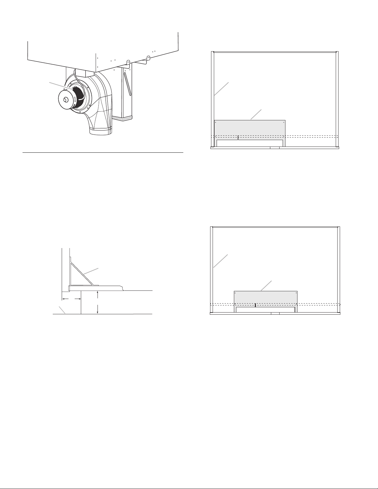
4. Verify the “Top” label is positioned as shown.
For a 30" (76.2 cm) base cabinet: The template will be located
in the front left corner. Note the area to be cut out of the cabinet
floor is in the toe-kick area.
Top View of Cabinet
A
A. Top label
Prepare the Base Cabinet Bottom
Installation of the Jenn-Air® Duct Free Filter System requires
modification to the cabinet base bottom in the toe-kick area of
the base cabinet. A cutout and 4 pilot holes are required for
mounting the Duct Free filter housing.
Remove Cabinet Brace
1. Open the cabinet doors.
2. Determine if a wooden or plastic brace is attached to the
cabinet floor and to the back of the center mullion as shown
in the following illustration.
E
D
B
C
A
A. Front of cabinet
B. Area to be cut out
C. Toe kick
D. Template
E. Left side of cabinet
For a 36" (91.4 cm) base cabinet: The poster board template
will be located closer to the center of the cabinet. Note the area
to be cut out of the cabinet floor is in the toe kick.
Top View of Cabinet
E
A
B
D
C
A. Brace
B. 2½" (6.4 cm)
C. 3" (7.6 cm)
D. Floor
3. If a wooden or plastic brace is installed, remove the brace.
Cabinet Floor Cutout
The installation of the Jenn-Air® Duct Free Filter System
Accessory Kit is dependent upon the type of cooktop purchased
and the base cabinet dimension. For example, a 30" (76.2 cm)
cooktop is designed to fit in a 30" (76.2 cm) base cabinet and a
36" (91.4 cm) cooktop is designed to fit in a 36" (91.4 cm) base
cabinet.
The poster board template provided with the kit is universal.
However, the actual location of the exhaust cutout is different
between the 30" (76.2 cm) and 36" (91.4 cm) products and due to
the length difference between the base cabinets. The sketches
that follow show the general position of the template.
D
B
C
A
A. Front of cabinet
B. Area to be cut out
C. Toe kick
D. Template
E. Left side of cabinet
NOTE: For illustration purposes, the cabinet front is not shown in
most of the following illustrations.
IMPORTANT: Do not cut the cabinet front.
4
Page 5
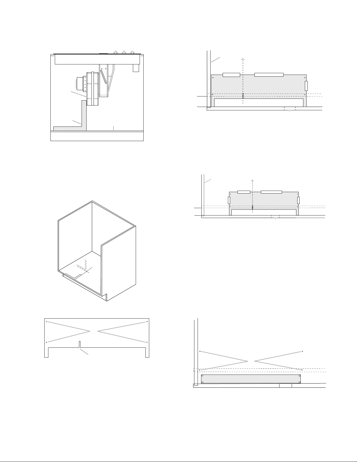
Cutout Steps
1. Use the framing square and draw a line on the cabinet floor
parallel to the edge of the blower exhaust scroll.
Front View of Cabinet
A
6. Tape template to bottom of cabinet with masking tape as
shown in the following illustrations.
30" (76.2 cm) Base Cabinet Template Position
Top View of Cabinet
A
B
A. Blower exhaust scroll
B. Framing square
C. Cabinet floor
C
2. Flip the framing square over and slide it against the cabinet
front.
3. Extend the line made in Step 1 to the cabinet front.
NOTE: For clarity, the cabinet front is not shown in this view.
4. Locate template included with the installation kit.
B
A. Left side of cabinet
B. Toe-kick area
C. Area to be cut out
D. Cabinet front
E. Center mullion
C
D
E
36" (91.4 cm) Base Cabinet Template Position
Top View of Cabinet
A
B
D
A. Left side of cabinet
B. Toe-kick area
C. Area to be cut out
D. Cabinet front
E. Center mullion
C
E
7. Trace the rectangle formed by the template onto the cabinet
floor. This is the area to be cut (C).
8. Use a set-punch and hammer to center-punch locations of
the housing assembly pilot holes in the cabinet floor.
9. Remove the template and tape. This will reveal the cutout
location and the pilot holes to be drilled in the cabinet bottom
(30" [76.2 cm] base cabinet installation shown).
Top View of Cabinet
A
B
A. Pilot hole locations
B. Alignment notch
5. Center the line made in Step 3 within the alignment notch of
the template. Make sure the edge of the template is against
the cabinet front.
A
B
A. Housing assembly pilot hole locations
B. Area to be cut out
5
Page 6

10. Use a drill with an ⁷⁄₆₄" (2.8 mm) drill bit to predrill
4 pilot holes used for mounting the housing assembly to the
cabinet floor.
11. Change the drill bit to a ¼" (6.4 mm) drill bit. Drill 4 through-
holes within the outline of the rectangle traced onto the
cabinet floor.
Top View of Cabinet
36" (91.4 cm) base cabinet with the opening cut into the
cabinet floor.
Top View of Cabinet
A
A. Cutout pilot hole locations
12. Use a jigsaw to cut along the outline at points 1 and 2.
At point 3, for a 30" (76.2 cm) base cabinet only, a hand-held
keyhole saw will be needed to complete the cut.
Top View of Cabinet
2
3
1
13. Use a hammer to tap on the cut piece of the cabinet floor
bottom until it falls out.
NOTE: Some cabinets will have brads, nails or staples.
Others will use glue to attach the cabinet floor bottom to the
cabinet front. If brads, nails or staples are present, remove
with pliers and properly dispose of these items.
30" (76.2 cm) base cabinet with the opening cut into the
cabinet floor.
Top View of Cabinet
Assemble Filter System
1. Open the 2 latches on top of the blower transition.
2. Open the filter access door.
3. Remove the filter from the housing assembly. The filter will be
reinstalled at the end of the installation process.
4. For 30" (76.2 cm) base cabinet installation only:
a.) Preinstall 2 - #8 AB x ½" black screws provided with kit
into the predrilled holes in the cabinet floor next to the left
side cabinet wall.
Top View of Cabinet
A
B
C
A. Left side cabinet wall
B. Predrilled holes in floor
C. Toe-kick area
b.) Leave approximately an ¹⁄₈" (3.2 mm) gap between the
bottom of the screw head and the cabinet floor.
¹⁄₈"
(3.2 mm)
c.) Place the housing assembly into the cutout in the cabinet
floor aligning the slotted flange on the left side under the
screw heads (A).
6
Page 7

d.) Install 2 - #8 AB x ½" screws (B) through the round holes
A
in the right side of the housing and into the predrilled
holes in the cabinet floor and tighten.
Top View of Cabinet
6. Attach the other end of the flex duct to the top of the blower
transition with 1 clamp.
7. Remove and dispose of/recycle the plastic bag that covers
the filter.
®
8. Activate the Time Strip
sensor by pressing the button on the
front of the filter.
A
A. Left side preinstalled screws
B. Right side screws
B
e.) Tighten the 2 - #8 AB x ½" screws on the left side (A).
For 36" (91.4 cm) base cabinet installation
a.) Place the housing assembly into the cutout in the cabinet
floor aligning the slotted flange with predrilled holes in
cabinet floor.
Top View of Cabinet
A
A
A. Time strip sensor
9. Insert the filter back into the Duct Free filter housing so that
the Time Strip
®
sensor can be seen through the opening in
the front of the filter housing when the cabinet door is
opened.
10. Close the filter access door and close the latches attached to
the top of the blower transition.
View of Completed Installation
A. 4 - #8 AB x ½" screws
b.) Install 4 - #8 AB x ½" screws (A) through the round holes
in the housing and into the predrilled holes in the cabinet
floor and tighten.
5. Attach one end of the flex duct to the blower exhaust scroll
with 1 clamp.
Front View of Cabinet
A
B
C
A. Blower exhaust scroll
B. Clamp
C. Flex duct
A
B
A. Front of cabinet
B. Exhaust airflow
7
Page 8

Check Operation
1. Turn the downdraft system on HI and verify the following:
■ Determine that there is airflow coming out through the toe
kick area.
■ Determine that there are no air leaks around the flex hose
clamps.
2. Follow the instructions on the Flow Test Card provided with
the kit to verify the installation.
TROUBLESHOOTING
No airflow through the system out the toe-kick area of the cabinet
Filter System Care
The Jenn-Air® Duct Free Filter System is designed to require
minimal attention between filter changes.
The filter is designed to last 6 months after the Time Strip
is activated. Verify the Time Strip® weekly.
The housing can be cleaned with a paper towel and household
cleaners or with a cloth and warm soapy water. No special
cleaners are required.
®
sensor
For gas installation :
WARNING
Electrical Shock Hazard
Plug into a grounded 3 prong outlet.
Do not remove ground prong.
Do not use an adapter.
Do not use an extension cord.
Failure to follow these instructions can result in death,
fire, or electrical shock.
■ Is the power supply cord to the cooktop unplugged ?
Plug the power cord from the cooktop into a grounded
3 prong outlet
For electric installation:
■ Is the power supply breaker tripped or the fuse blown?
Reset the breaker or replace the fuse.
The downdraft blower attached to the cooktop creates the air
flow that flows down through the Duct Free system. If no
power is supplied to the cooktop, the system will not work.
■ Is the Time Strip
Replace the filter.
■ Has the plastic bag been removed from the filter?
Remove and dispose of/recycle the plastic bag.
■ Is the Duct Free Filter housing door shut, and are the door
latches closed?
Firmly close the filter housing door and door latches.
®
sensor window red?
8
Page 9

SÉCURITÉ DU FILTRE D’ÉVACUATION PAR LE BAS
Votre sécurité et celle des autres est très importante.
Nous donnons de nombreux messages de sécurité importants dans ce manuel et sur votre appareil ménager. Assurez-vous de
toujours lire tous les messages de sécurité et de vous y conformer.
Voici le symbole d’alerte de sécurité.
Ce symbole d’alerte de sécurité vous signale les dangers potentiels de décès et de blessures graves à vous
et à d’autres.
Tous les messages de sécurité suivront le symbole d’alerte de sécurité et le mot “DANGER” ou
“AVERTISSEMENT”. Ces mots signifient :
Risque possible de décès ou de blessure grave si vous ne
DANGER
AVERTISSEMENT
Tous les messages de sécurité vous diront quel est le danger potentiel et vous disent comment réduire le risque de blessure et
ce qui peut se produire en cas de non-respect des instructions.
CONSIGNES IMPORTANTES :
Le système de filtrage sans conduit filtre l’air du circuit d’évacuation par le bas et évacue l’air filtré dans la pièce à travers le
dégagement de la plinthe du placard inférieur. Ne pas évacuer l’air du circuit dans le placard inférieur ou son socle, un vide sanitaire, un
mur ou un grenier.
La cartouche filtrante est utilisable pendant six mois d’activité normale de cuisine. La cartouche filtrante sans conduit n’est pas prévue
pour être nettoyée et réutilisée. Le filtre doit être remplacé en fonction de l’indicateur Time Strip
préconisé, l’évacuation par le bas ne sera pas optimale.
suivez pas immédiatement les instructions.
Risque possible de décès ou de blessure grave si vous
ne suivez pas les instructions.
®
. Si le filtre n’est pas remplacé comme
9
Page 10

EXIGENCES D’INSTALLATION
Outils et pièces
Rassembler les outils et composants nécessaires avant
d’entreprendre l’installation. Lire et observer les instructions
fournies avec chacun des outils de la liste ci-dessous.
Outils nécessaires
■ Mètre-ruban
■ Équerre de charpentier
■ Marteau
■ Poinçon
■ Pince
■ Marqueur ou crayon
■ Tournevis à lame plate
■ Tournevis Phillips
■ Perceuse
■ Foret de ¼" (6,4 mm)
■ Foret de ⁷⁄₆₄" (2,8 mm)
■ Scie sauteuse ou scie à guichet
■ Ruban adhésif de masquage
Pièces fournies
■ Fiche de test du débit
■ Gabarit en carton résistant
■ Logement de filtre sans conduit
■ Conduit flexible
■ 2 brides
■ Filtre sans conduit à indicateur de durée d’utilisation Time
■ 4 vis de montage
Strip
®
Exigences d’emplacement
Le système de filtrage sans conduit Jenn-Air® est approuvé pour
les produits d’évacuation par le bas Jenn-Air des séries
JED3430, JED3536, JED 4430, JED4546, JGD3430 et JGD3536.
Le système de filtrage sans conduit Jenn-Air
dans un meuble fabriqué selon les critères de KCMA (Kitchen
Cabinet Manufacturers Association) concernant le dégagement
de la plinthe. D’après le minimum de KCMA, le dégagement de la
plinthe doit avoir une profondeur de 2½" (6,4 cm) et une hauteur
de 3" (7,6 cm), comme illustré dans la figure.
B
A
C
A. Plancher
B. 2½" (6,4 cm)
C. 3" (7,6 cm)
Filtre sans conduit
L’ensemble pour système de filtrage sans conduit Jenn-Air
contient 1 cartouche filtrante sans conduit. Le filtre inclus dans
l’ensemble est équipé d’un indicateur Time Strip
d’utilisation de 6 mois. L'indicateur Time Strip
fois le filtre installé dans son logement.
Une fois l’installation terminée, appuyer sur le bouton de
l’indicateur Time Strip
®
pour l’activer. Une fois activé, l’indicateur
Time Strip® s’assombrit régulièrement le long de l’indicateur de
temps jusqu’à ce que les 6 mois soient écoulés.
Il est possible de commander un filtre de rechange JDA8000WX
en composant 1-800-JENNAIR (1-800-536-6247) ou en visitant le
site Web www.jennair.com.
Au Canada, composer le 1-800-807-6777 ou consulter le site
Internet www.jennair.ca.
®
doit être installé
®
®
de durée
®
est visible une
10
Page 11

INSTRUCTIONS D’INSTALLATION
E
Installation de la table de cuisson dans le meuble
Suivre les consignes recommandées par le fabricant pour
installer la table de cuisson à évacuation par le bas, spirale
d’échappement tournée à la verticale vers le bas.
Pour faire pivoter la spirale d’échappement du ventilateur vers le
bas, effectuer les étapes suivantes.
Rotation du ventilateur
IMPORTANT : Les étapes supplémentaires suivantes doivent
être effectuées si la table de cuisson est installée avec une
configuration passe-plats ou en îlot.
Au déballage, la spirale d’échappement du ventilateur est
orientée vers l’arrière du placard, pour une évacuation à travers
une paroi extérieure.
D
E
C
A
F
A. Spirale d’échappement du
ventilateur
B. Plénum
C. Moteur du ventilateur
E
B
D. Étiquette indiquant le haut (Top)
E. Écrous mécaniques 10-32 (qté 4)
F. Platine de montage du moteur
3. Insérer la clé à douille de ³⁄₈" et la rallonge dans le trou et
dévisser l’écrou d’un demi-tour à l’aide de la poignée à
cliquet. Répéter l’opération pour les 4 autres écrous.
4. Une fois les écrous desserrés, la spirale d’échappement du
ventilateur s’oriente sans effort vers le bas.
5. Resserrer chaque écrou à l’aide de la clé à cliquet à douille
de ³⁄₈".
6. Réinstaller les 4 bouchons en plastique.
Pour tourner le moteur du ventilateur :
REMARQUE : L’emplacement de l’étiquette indiquant le haut
(Top) sur le moteur du ventilateur est à la position de 9 heures.
1. À l’aide d’une clé à cliquet à douille de ³⁄₈" et en soutenant le
moteur d’une main, dévisser les 4 écrous mécaniques qui
maintiennent le moteur du ventilateur à la spirale
d’échappement.
2. Dégager l’ensemble moteur-roue des goujons soudés.
Pour tourner le ventilateur :
1. Localiser les 4 bouchons en plastique dans le volet du
plénum.
2. Les enlever à l’aide d’une pince.
IMPORTANT : Ne pas jeter les bouchons en plastique. Les
bouchons en plastique doivent être réinstallés une fois la
spirale d’échappement du ventilateur tournée.
A
B
C
A. Moteur du ventilateur
B. Spirale d’échappement
C. Plénum
D
D. Volet du plénum
E. Bouchons en plastique
(qté 4)
D
A
B
E
C
A. Étiquette indiquant le haut (Top)
B. Moteur du ventilateur
C. Platine de montage du moteur
3. Lorsque la platine de montage du moteur sort des goujons
soudés filetés, tourner l’ensemble de 90° dans le sens horaire
et revisser les 4 écrous n° 10-32.
D. Emplacement des goujons
soudés
E. Roue du ventilateur
11
Page 12

4. Vérifier que l’étiquette “Top” est placée comme illustré.
Pour un placard inférieur de 30" (76,2 cm) : Le gabarit sera
placé dans le coin avant gauche. Noter que la zone du plancher
du placard à découper se trouve dans le dégagement de la
plinthe.
Placard vu de dessus
A
A. Étiquette indiquant le haut (Top)
Préparation du plancher du
placard inférieur
L’installation du système de filtrage sans conduit Jenn-Air®
impose de modifier le plancher du placard inférieur au niveau du
dégagement de la plinthe. Une découpe et 4 avant-trous sont
nécessaires pour installer le logement du filtre sans conduit.
Démontage de l’équerre de renfort
1. Ouvrir les portes du placard.
2. Déterminer si une équerre en plastique ou en bois est fixée au
plancher du placard et à l’arrière du montant central comme
illustré dans la figure suivante.
E
D
B
C
A
A. Avant du placard
B. Zone à découper
C. Plinthe
D. Gabarit
E. Côté gauche du placard
Pour un placard inférieur de 36" (91,4 cm) : Le gabarit en
carton résistant sera placé plus près du centre du placard. Noter
que la zone du plancher du placard à découper se trouve dans la
zone de la plinthe.
Placard vu de dessus
A
B
D
C
A. Équerre
B. 2½" (6,4 cm)
C. 3" (7,6 cm)
D. Plancher
3. Si une équerre en bois ou en plastique est installée, la
démonter.
Découpe du plancher du placard
L’installation de l’ensemble pour système de filtrage sans conduit
Jenn-Air® dépend du type de table de cuisson et des dimensions
du placard inférieur. Par exemple, une table de cuisson de
30" (76,2 cm) est acceptable dans un placard inférieur de
30" (76,2 cm) et une table de cuisson de 36" (91,4 cm) convient
pour un placard inférieur de 36" (91,4 cm).
Le gabarit en carton résistant fourni est universel. Cependant,
l’emplacement de la découpe de l’évacuation varie entre les
produits de 30" (76,2 cm) et de 36" (91,4 cm) en raison des
différentes longueurs des placards inférieurs. Les schémas cidessous illustrent la position générale du gabarit.
E
D
B
C
A
A. Avant du placard
B. Zone à découper
C. Plinthe
D. Gabarit
E. Côté gauche du placard
REMARQUE : À des fins de lisibilité, l’avant du placard n’est pas
représenté dans la plupart des illustrations suivantes.
IMPORTANT : Ne pas découper l’avant du placard.
12
Page 13

Étapes de la découpe
1. À l’aide de l’équerre de charpentier, tracer un trait sur le
plancher du placard à l’aplomb du flanc de la spirale
d’échappement du ventilateur.
Placard vu de dessus
Position du gabarit dans un placard inférieur de 30" (76,2 cm)
Placard vu de dessus
A
A
B
A. Spirale d’échappement du ventilateur
B. Équerre de charpentier
C. Plancher du placard
C
2. Retourner l’équerre de charpentier et la glisser contre l’avant
du placard.
3. Prolonger le trait tracé à l’étape 1 jusqu’à l’avant du placard.
REMARQUE : Pour des raisons de clarté, l’avant du placard
n’est pas représenté dans cette vue.
B
A. Côté gauche du placard
B. Dégagement de la plinthe
C. Zone à découper
D. Avant du placard
E. Montant central
C
D
E
Position du gabarit dans un placard inférieur de 36" (91,4 cm)
Placard vu de dessus
A
B
D
A. Côté gauche du placard
B. Dégagement de la plinthe
C. Zone à découper
D. Avant du placard
E. Montant central
C
E
7. Tracer le rectangle délimité par le gabarit sur le plancher du
placard. Il s’agit de la partie à découper (C).
8. À l’aide d’un poinçon et d’un marteau, marquer les
emplacements des avant-trous pour le logement de filtre
dans le plancher du placard.
9. Retirer le gabarit et le ruban adhésif. L’emplacement de la
découpe et des avant-trous à percer est indiqué sur le
plancher du placard (illustration d’une installation dans un
placard inférieur de 30" [76,2 cm]).
Placard vu de dessus
4. Rechercher le gabarit inclus dans l’ensemble d’installation.
A
B
A. Emplacement des avant-trous
B. Entaille d’alignement
5. Centrer le trait tracé dans l’étape 3 dans l’entaille
d’alignement du gabarit. S’assurer que le bord du gabarit est
aligné sur l’avant du placard.
6. Fixer le gabarit au plancher du placard à l’aide de ruban
adhésif de masquage, comme illustré dans les figures
suivantes.
A
B
A. Emplacement des avant-trous du
logement de filtre
B. Zone à découper
10. À l’aide d’une perceuse équipée d’un foret de ⁷⁄₆₄" (2,8 mm),
percer 4 avant-trous qui serviront à monter le logement de
filtre sur le plancher du placard.
13
Page 14

11. Remplacer le foret par un foret de ¼" (6,4 mm). Percer 4
avant-trous aux coins du rectangle tracé sur le plancher du
placard.
Placard vu de dessus
A
A. Emplacement des avant-trous de la découpe
12. À l’aide d’une scie circulaire, découper le long du tracé les
côtés 1 et 2.
Au côté 3, pour un placard inférieur de 30" (76,2 cm)
uniquement, une scie à guichet manuelle est nécessaire pour
terminer la découpe.
Placard vu de dessus
Placard inférieur de 36" (91,4 cm) avec ouverture évidée dans
le plancher.
Placard vu de dessus
Assemblage du système de filtrage
1. Ouvrir les 2 attaches sur le dessus du raccord au ventilateur.
2. Ouvrir la trappe d’accès au filtre.
3. Retirer le filtre de son logement. Le filtre sera réinstallé à la fin
de la procédure d’installation.
2
3
1
13. À l’aide d’un marteau, taper légèrement sur la pièce
découpée du plancher du placard pour la faire tomber.
REMARQUE : Certains placards contiennent des broches,
des clous ou des agrafes. D’autres utilisent de la colle pour
fixer le plancher du placard à l’avant. Retirer les broches,
clous ou agrafes éventuels à l’aide d'une pince et les jeter de
manière adéquate.
Placard inférieur de 30" (76,2 cm) avec ouverture évidée dans
le plancher.
Placard vu de dessus
4. Pour une installation dans un placard inférieur de 30"
(76,2 cm) uniquement :
a.) Placer les 2 vis noires n° 8 AB x ½" fournies dans les
avant-trous du plancher du placard, près de la paroi
gauche.
Placard vu de dessus
A
B
C
A. Paroi gauche du placard
B. Avant-trou dans le plancher
C. Dégagement de la plinthe
b.) Laisser un espace d’environ ¹⁄₈" (3,2 mm) entre le bas de
la tête de vis et le plancher du placard.
14
¹⁄₈"
(3,2 mm)
Page 15

c.) Placer le logement du filtre dans la découpe du plancher
A
du placard en plaçant la collerette à encoches de gauche
sous les têtes de vis (A).
d.) Visser 2 vis n° 8 AB x ½" (B) à travers les trous à droite du
logement dans les avant-trous du plancher du placard et
serrer.
Placard vu de dessus
Vue avant du placard
A
B
C
A
A. Vis non serrées à gauche
B. Vis de droite
B
e.) Serrer les 2 vis n° 8 AB x ½" à gauche (A).
Pour une installation dans un placard inférieur de
36" (91,4 cm) :
a.) Placer le logement du filtre dans la découpe du plancher
du placard, en alignant la collerette à encoches avec les
avant-trous dans le plancher du placard.
Placard vu de dessus
A
A. Spirale d’échappement du ventilateur
B. Bride
C. Conduit flexible
6. Fixer l’autre extrémité du conduit flexible au sommet du
raccord du ventilateur à l’aide d’une bride.
7. Ôter le sac plastique protégeant le filtre et le jeter/recycler.
8. Activer l’indicateur Time Strip
®
en appuyant sur le bouton à
l’avant du filtre.
A
A. Indicateur de durée d’utilisation Time Strip®
9. Réinsérer le filtre dans son logement de sorte que l’indicateur
Time Strip
®
soit visible par la fenêtre à l’avant du logement de
filtre lorsque la porte du placard est ouverte.
A. 4 vis n° 8 AB x ½"
b.) Visser 4 vis n° 8 AB x ½" (A) à travers les trous ronds du
logement dans les avant-trous du plancher du placard et
serrer.
5. Fixer une extrémité du conduit flexible à la spirale
d’échappement du ventilateur à l’aide d’une bride.
15
Page 16

10. Fermer la trappe d’accès au filtre et verrouiller les attaches
©
sur le dessus du raccord du ventilateur.
Vue de l’installation terminée
A
B
A. Avant du placard
B. Flux de l’air évacué
Contrôle du fonctionnement
1. Régler le système d’évacuation par le bas sur le régime élevé
(HI) et effectuer les vérifications suivantes :
■ Contrôler qu’un souffle d’air sort par le dégagement de la
plinthe.
■ Vérifier qu’il n’existe aucune fuite d’air autour des brides
du conduit flexible.
2. Suivre les consignes de la fiche de test du débit fournie pour
vérifier l’installation.
Entretien du système de filtrage
L’entretien du système de filtrage sans conduit Jenn-Air® est
minimal entre les remplacements de filtre.
Le filtre est conçu pour durer 6 mois une fois l’indicateur Time
®
activé. Vérifier l’indicateur Time Strip® toutes les semaines.
Strip
Le logement se nettoie avec un essuie-tout en papier et un
nettoyant ménager ou un chiffon et de l’eau savonneuse tiède.
Aucun nettoyant particulier n’est préconisé.
DÉPANNAGE
Absence de circulation d’air à la sortie du système par le dégagement de la plinthe du placard
Pour une installation au gaz :
AVERTISSEMENT
Risque de choc électrique
Brancher sur une prise à 3 alvéoles reliée à la terre.
Ne pas enlever la broche de liaison à la terre.
Ne pas utiliser un adaptateur.
Ne pas utiliser un câble de rallonge.
Le non-respect de ces instructions peut causer
un décès, un incendie ou un choc électrique.
■ Le cordon d’alimentation de la table de cuisson est-il
débranché? Brancher le cordon d’alimentation de la table de
cuisson dans une prise à 3 alvéoles reliée à la terre.
Pour une installation électrique :
■ Le disjoncteur s’est-il déclenché ou un fusible est-il
grillé?
Réenclencher le disjoncteur ou remplacer le fusible.
Le ventilateur fixé à la table de cuisson crée un flux d’air qui
circule vers le bas à travers le système sans conduit. Si la
table de cuisson n’est reliée à aucune alimentation électrique,
le système ne fonctionne pas.
■ La fenêtre de l’indicateur Time Strip
Remplacer le filtre.
■ Le sac en plastique a-t-il été ôté du filtre?
Ôter le sac en plastique et le jeter/recycler.
■ La trappe d’accès au filtre est-elle fermée et ses attaches
sont-elles verrouillées?
Fermer la trappe d’accès au filtre et verrouiller les attaches de
la trappe.
®
est-elle rouge?
W10254051A
2009.
All rights reserved.
Tous droits réservés.
® Registered Trademark/TM Trademark of Jenn-Air, U.S.A. Used under license by Maytag Limited in Canada.
®Marque déposée/TM Marque de commerce de Jenn-Air, U.S.A. Emploi sous licence par Maytag Limited au Canada.
Printed in U.S.A.
Imprimé aux É.-U.
6/09
 Loading...