

Jenn-Air CVEX4100B19, CVEX4100W19, CVEX4270B, CVEX4270B19, CVEX4270W19 Installation Guide
...Page 1
ExpressionsConvertible I JENN-AIi;-
CooktopSeries ._WESTFO0..._TOEET,_'H.._ON,,.0
Models CVEX4100, CVEX4270 & CVEX4370
IMPORTANT
• Installation should be performed by a Jenn-Air authorized servicer or other qualified installer,
• Read Safety Precautions in the Use & Care manual before using this appliance.
INSTALLER
• Save installation instructions for local electrical inspector's use.
• Leave installation instructions with the appliance.
CONSUMER
° Retain installation instructions with the appliance.
I
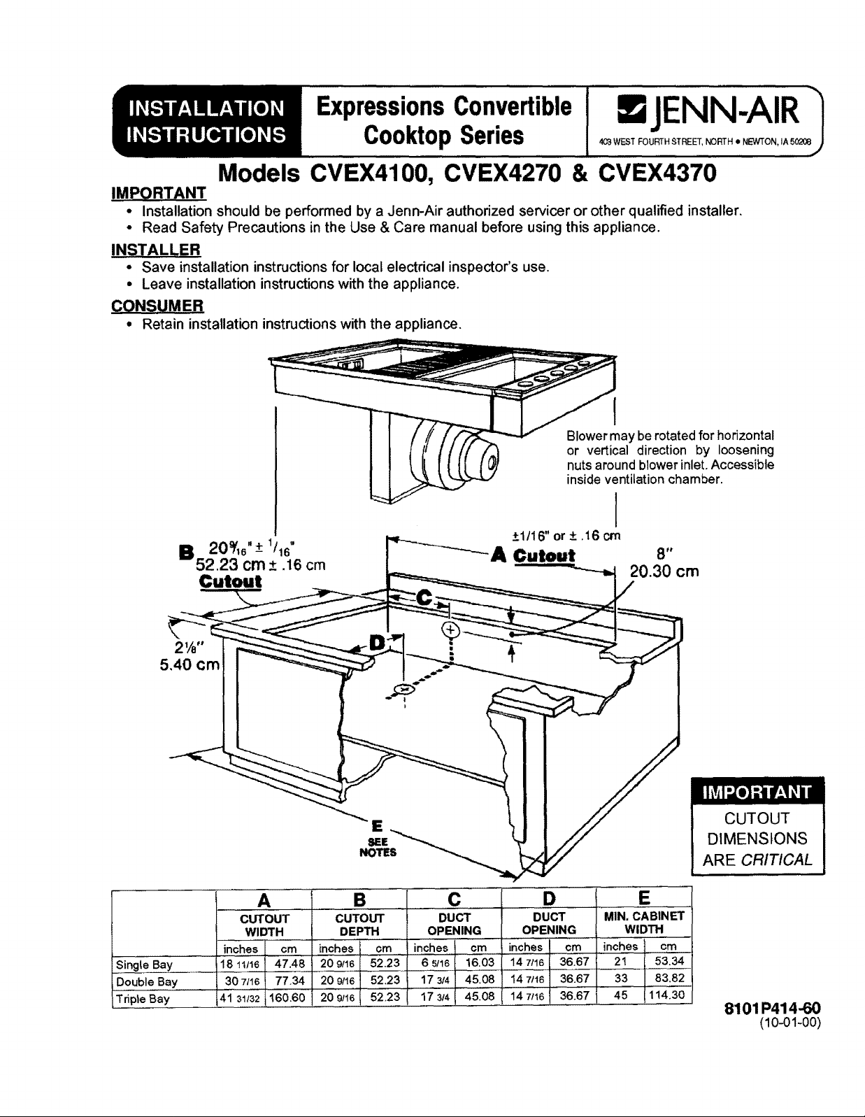
Blower may berotated for horizontal
or vertical direction by loosening
nuts around blower inlet. Accessible
inside ventilation chamber.
I
±1/16" or + .16 crn
A Cutout
Sir_j!____reBay
DoubleBaY
Tripte Bay
Cutout
5,40 cm
A ...........
CUTOUT
WIDTH
inches cm
18 11116 47.48
30 7/16 77.34
41 31132 160.60
E
SEE
NOTES
S ....
CUTOUT
DEPTH
inches cm
I 20 9/16 52,23
20 9/16 52,23
20 9/16 I 52.23 17 314
inches cm
6 _,116 16.03
17 3/4 45,08
C
DUCT
OPENING
45.08
D
DUCT
OPENING
inches cm
14 7/16 36.67
14 7/16 36.67
14 7116 36.67
CUTOUT
DIMENSIONS
ARE CRITICAL
MIN, CABINET
WIDTH
inches cm
21 53.34
33 83.82
45 1!4.30
8101 P414-60
(10-01-00)
Page 2
See side clearance--------)l
note below.
Min. I 1 I12.ol cm
Clearanoe ]J-----1_ *
Required ,._,, [] _ Grease
17 1/2" I II 1 I I Container
44"46cm [__,,_ LJSEENOT E
See side clearance_I _ _-
note below.
Min.
Clearance ,,.
Required
17 1/2"
44.46 cm
SINGLE
'" L ,,I, ,,
- ;- r-_ 4 3t4"
--_-- 12 1/2 -_ BELOW
31.76crn
DOUBLE
IIILli
I _fl _- J SEE NOTE
_12 1/2L-_ BELOW
31.76cm
4,
t"
K SEENOTE
BELOW
4,
1"
K SEE NOTE
BELOW
TRIPLE
See side clearancei-----) I
note below
.in
Clearance-" _-_11z116_._tl I IlL.
;,_::ircemd 2906cm17 1/2" i1_"m SEE NOTE
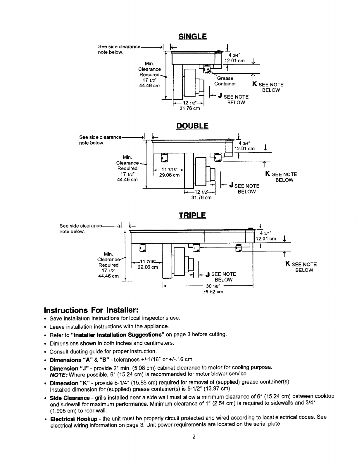
Instructions For Installer:
• Save installationinstructions for local inspector'suse.
° Leave installation instructions with the appliance.
• Refer to "installer Installation Suggestions" on page 3 before cutting.
• Dimensions shownin both inchesandcentimeters
• Consult ductingguidefor proper instruction,
• Dimensions "A" & "B" - tolerances+/-t/16" or +/-.16 cm.
• Dimension "J" - provide2" rain (5.08 cm)cabinetclearance to motorfor coolingpurpose.
NOTE:Where possible,6" (15,24 cm) is recommended for motor blower service.
• Dimension "K" - provide6-1/4" (15.88 cm) requiredfor removal of (supplied)greasecontainer(s).
Installed dimensionfor (supplied)grease container(s) is 5-1/2" (!3.97 cm)
• Side Clearance - grillsinstallednear a sidewall mustallowa minimum clearance of 6" (15.24 cm) between cooktop
and sidewallfor maximum performance.Minimum clearance of 1" (2.54 cm) is required to sidewallsand 314"
(1905 cm) to rear wall.
• Electrical Hookup - the unit mustbe properlycircuitprotectedandwiredaccordingto localelectricalcodes, See
electrica!wiringinformationon page 3. Unit power requirementsare !ocated on the serialplate.
k-
i i ii
BELOW
30 t/8"
76.52 cm
-'_ 3/4"
12.01cm
{
$
1"
K SEE NOTE
BELOW
Page 3
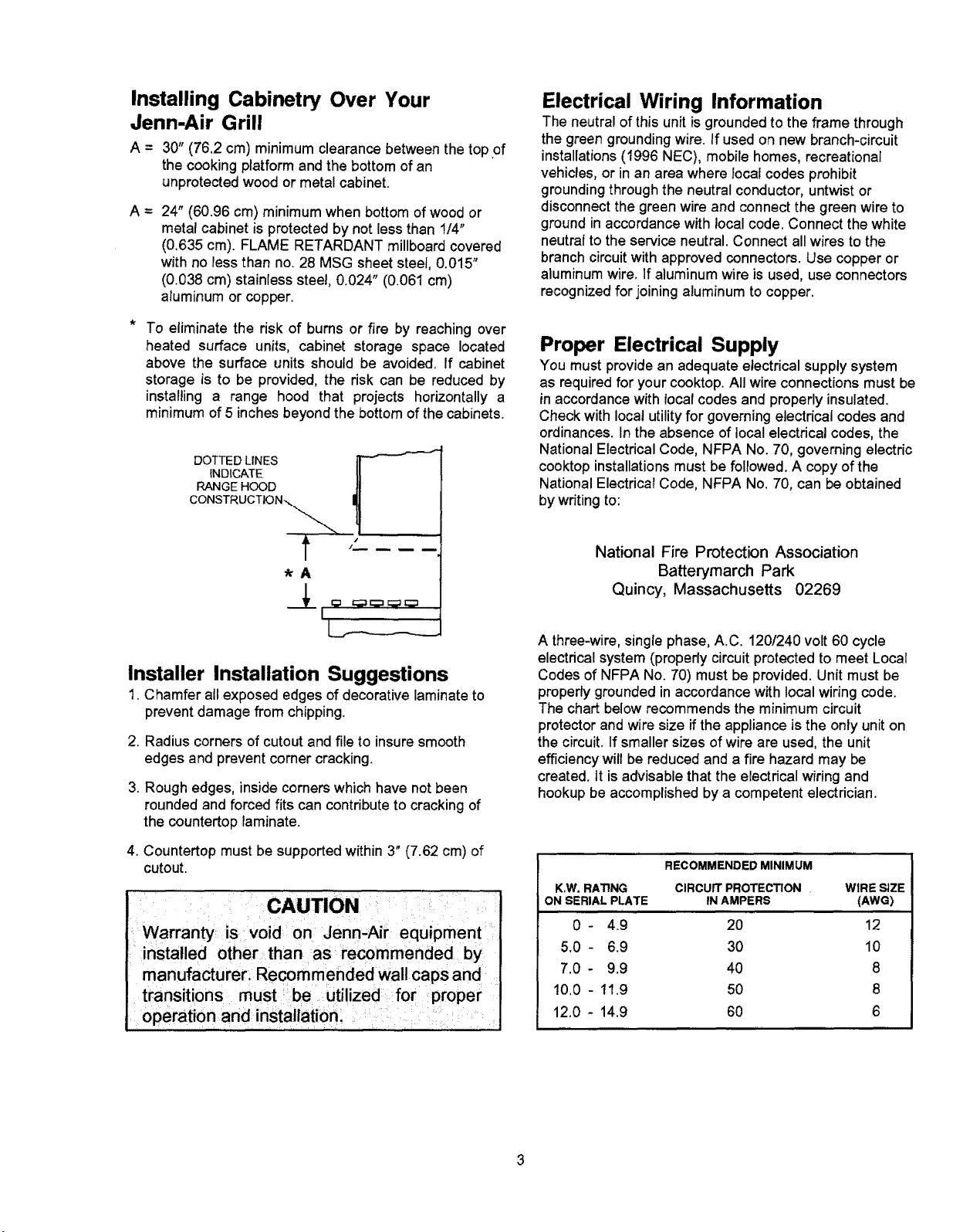
Installing Cabinetry Over Your
Jenn-Air Grill
A = 30" (76.2 cm) minimum clearance between the top of
the cooking platform and the bottom of an
unprotected wood or metal cabinet.
A = 24" (60.96 cm) minimum when bottom ofwoodor
metal cabinet is protected by not less than !/4"
(0.635 cm). FLAME RETARDANT millboard covered
with no less than no. 28 MSG sheet steel, 0.015"
(0.038 cm) stainless steel, 0.024" (0.061 cm)
aluminum or copper.
To eliminate the risk of burns or fire by reaching over
heated surface units, cabinet storage space located
above the surface units should be avoided, If cabinet
storage is to be provided, the risk can be reduced by
installing a range hood that projects horizontally a
minimum of 5 inches beyond the bottom of the cabinets.
INDICATE
RANGE HOOD
DOTTED LINES _-_
CONSTRUCTION_
Electrical Wiring Information
The neutralof thisunitisgrounded to the frame through
the green grounding wire. If used on new branch-circuit
installations (1996 NEC), mobile homes, recreational
vehicles, or in an area where local codes prohibit
grounding through the neutral conductor, untwist or
disconnect the green wire and connect the green wire to
ground in accordance with local code. Connect the white
neutral to the service neutral. Connect all wires to the
branch circuit with approved connectors. Use copper or
aluminum wire. If aluminum wire is used, use connectors
recognized for joining aluminum to copper.
Proper Electrical Supply
You must provide an adequate electrical supply system
as required for your cooktop. All wire connections must be
in accordance with focal codes and properly insulated.
Check with local utility for governing electrical codes and
ordinances. In the absence of local electrical codes, the
National Electrical Code, NFPA No. 70, governing electric
cooktop installations must be followed. A copy of the
National Electricat Code, NFPA No. 70, can be obtained
by writing to;
t '
*A
I
Installer Installation Suggestions
1. Chamfer all exposed edges of decorative laminate to
prevent damage from chipping.
2. Radius corners of cutout and file to insure smooth
edges and prevent corner cracking.
3. Rough edges, inside corners whichhave not been
rounded and forced fits can contribute to cracking of
the countertop laminate.
4. Countertop must be supportedwithin 3" (7.62 cm) of
cutout.
CAUTION
Warranty is void on Jenn-Air equipment
installed other than as recommended by
manufacturer. Recommended wall caps and
transitions must be utilized for proper
operation and installation.
National Fire Protection Association
Batterymarch Park
Quincy, Massachusetts 02269
A three-wire,single phase, A.C. 120/240 volt 60 cycle
electrical system (properly circuit protected to meet Local
Codes of NFPA No. 70) must be provided. Unit must be
properly grounded in accordance with local wiring code.
The chart below recommends the minimum circuit
protector and wire size if the appliance is the only unit on
the circuit. If smaller sizes of wire are used, the unit
efficiency will be reduced and a fire hazard may be
created, it is advisable that the electrical wiring and
hookup be accomplished by a competent electrician.
RECOMMENDED MINIMUM
K,W. RATING CIRCUIT PROTECTION • WIRE SIZE
ON SERIAL PLATE IN AMPERS (AWG)
0- 4.9 20 12
5.0- 6.9 30 10
7.0- 9.9 40 8
!0.0 - 11.9 50 8
12.0 - 14.9 60 6
Page 4

Preparing Unit For Assembly In Countertop
1, Unpack Unit.
2. Provide cutout for countertop and duct openings as
required per page 1.
3. Place unit in the cutout, and slide unit all the way to the
left hand side of cutout. (Figure 1).
4. HOLDING DOWN UNIT TO COUNTERTOP: Use the
hold down straps, provided in the hardware package, to
secure unit to the countertop. These straps may be
positioned on the left, front, and back sides of the unit.
(See figure 1A). To install, pre-thread the bolt into the
strap about 2 inches. With the unit positioned in the
cutout as desired, reach through the cabinet door
opening and push up along the wall of the burner box
flange. If it doesn't hook, pull strap down, move it left or
right about an inch and push up again. Once strap is
hooked, thread bolt into strap until it meets resistance
against bottom of countertop. Then tighten slowly until
unit top bottoms against countertop.
5. Connect outlet of blower housing to vent duct. Loosen
cap nuts inside plenum to rotate blower housing to
desired position.
6. Remove attachment screw and cover from junction
box. Connect BX Cable power supply to knockout in
side of box. Make wire connections, push wires into
box. Re-attach cover. Consult local codes for proper
power hookup. (Figure 2).
7. Test to insure electronic surface control operates all
elements properly.
FIGURE 1A FIGURE !
JUNCTION BOX
\
FIGURE 2
Page 5

C_.stomer SeP:ic_
Z40EawardsSLreet,SE
C1eve!and,Tennessee37311
Tei:_22-472-3333
Fax:_23-478-6710
I0.
FLOOR VENT CUTOUT (JOISTS AS SHOWN)
- Check the direction of the floor joists (see illustration), tf the joists' direction is as shown, locate
the cutout on the '7" as illustrated. The cutout must miss the floarjoists!
- Cutout may be moved from side to side on line to clear floor joist.
- Recheck your dimensions and make the cutout.
11. FLOOR VENT CUTOUT (JOISTS AS SHOWN)
- Check the direction of the floor joists (see illustration). If the joists' direction is as shown, locate
the cutout on the T as illustrated. The cutout must miss the floor joist!!
- Cutout may be moved from front to back on line to clear floor joist.
- Recheck your dimensions and make the cutout.
!
12. WALL VENT CUTOUT
- Locate the vertical studs in the rear wall. Studs are usually t6 _ (40.64 cm) center to center.
- Wil! the vent duct be 6" (15.24 cm) round throug.h the wall or 3 1t4" x 10" (8.26 cm x 25.4 era)
rectangle, vertically inside the wall?
- See Ducting Instructions for rear duct inside the wall. NOTE: Cutout in walt must clear 3 1/4" x
10" (8.26 cm x 25.4 era) transition elbow.
- Locate the closest stud to your proposed vent hole location. Use the following chart to figure the
_X" dimension. See the illustration for the other dimensions.
) "X" MINIMUM
- A 1" (2.54 cm) length of duct must protrude through the wall for connection to the Blower.
6" Round (15.24 era) 3¼" x 10"
i VERTICAL DUCT INSIDE WALL
}. 4" (10.16 cm) 6" (15.24 era)
(8-26 cm x 25.4 era)
{ _ |c:.os_sTt
8'h" 61t_-
t43._ crop q
._4,_,'/I,\G Admiral 7! -'ttvl'_jl::NN-.A;l::t "_iI!,1_i€ C,_.e_
Page 6

2J-gEawa_dsStreeLSE
C;eveiand,Tennessee37311
Tel:423-477.-;333
Fax:'_23-J-78-67!0
13.
INSTALL BLOWER (PRIOR TO INSTALLING RANGE)
- Refer to your vent plan. It may be desirable to attach part of the ducting to the blower before it
is installed.
- Position the blower (see illustration) and attach it to the floor with at least two (2) screws.
- Apply duct tape around blower exhaust/duct joint.
THROUGH THROUGH
OUTSIDE WALl. THE FLOOR
r It .---.
rfZfTflVfl_l/ ff¢ ffJ'--J_ E.Z .."
14.
INSTALL ELECTRICAL oucr TAPE
METAL DUCT
- NOTE: Observe all local electrical codes.
- CAUTION: Make sure power to cable is OFF:
- Locate the electric power supply in the floor or wall, any place in the shaded areas which will
clear the blower.
- Direct Connect. Pull through 5' (152.4 cm) of electrical cable.
- Use three or four conductor copper stranded power cable (see front cover for proper wire size). If
four conductor wire is used, see #16 for connection to range.
- See front cover for proper supply connection. . _1"[ _eTRIC,_t.k
I5.
CONNECT ELECTRICAL (THREE CONDUCTOR WIRE)
- CAUTION: Make sure power to cable is OFF.
- Remove the range electrical service cover, located on the back, lower lefthand corner.
- [nstatl a 3/4" (I.91 cm) clamp in the hole provided below the terminal block.
- Strip 3" (7.62 cm) of outer insulation from the cable.
- Strip It2" (I .27 era) of insulation from each wire.
- Pull the cable through the cable clamp. Attach the BLACK, RED, and WHITE wires (see
illustration). Tighten the terminal block nuts and the cable clamp and install cover.
j I
I \I
4,/,"(_1._=_ SHADEDAREA \ i
---,4 ----- V
/ i _L_,._ _._ :-o_.tt . 1 $" (782 ¢m}
1 I
ELECTRICAL CAI_
Page 7

2_0Eawar_sE,tr_e[ %
C'.m:e,anaTe.nr_z_ee_7._11
Fax_2._-478-_70
16. CONNECT ELECTRICAL (FOUR CONDUCTOR WIRE)
- CAUTION: Make sure power to cable is OFF.
- Remove the range electrical service cover located on the back, lower left-hand corner. Remove the
ground strapscrew and bend the strap up as shown.
- [nstall a 3/4 (1.19 cm) cable clamp in the hole provided, below the terminal block.
- Strip 3" (7.62 cm) of outer insulation from the cable.
- Strip lt2" (1.27 era) of insulation from each wire.
- Pull the cable through the cable clamp.
- Make a loop in the bare ground wire and attach it to the range with the screw that held the _m'ound
strap.
- Attach the BLACK, RED, and WHITE wires (see #15). Tighten the terminal block nuts and the
cable clamp.
- Tape the ground strap to the WHITE wire as shown. Installelectrical cover.
17. INSTALL Ot_IONS
- If a backsplash or side panels are to be used, install according to instructions included with those
accessories.
18. POSITION RANGE
- Free-Standing: Adjust the range feet so the range and cabinet height wil! be approximately the
same. Slide the range into place, taking care not to damage floor coventlg.
- Slide-In: Carefully lift and place the range on the cabinet top.
.==,=,=.,=_ \
, _ 'WlRI::
a
i
|
J
Page 8
Cus[ome r _ePdc_
2_0EdwardsStreet,SE
Ceveian_.Tennessee373I I
Te!:a22-'72-3333
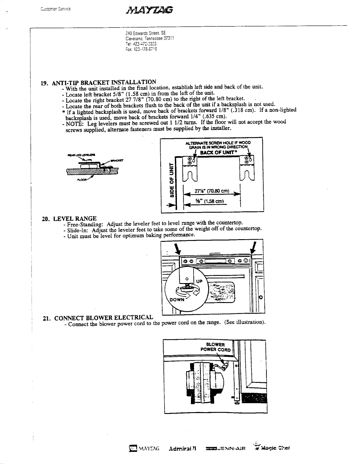
t9. ANTI-TIP BRACKET INSTALLATION
- With the unit installed in the final location, establish left side and back of the unit.
- Locate left bracket 5/8" (1.58 cm) in from the left of the unit.
- Locate the right bracket 27 718" (70.80 cm) to the right of the left bracket.
- Locate the rear of both brackets flush to the back of the unit if a backsplash is not used.
* Ira lighted backsptash is used, move back of brackets forward 1/8" (.3t8 cm). Ira non-lighted
backsp|ash is used, move back of brackets forward 1/4" (.635 cm).
- NOTE: I._g levelers must be screwed out I I/2 turns. If the floor will not accept the wood
screws supplied, alternate fasteners must be supplied by the installer.
mt_ot t.zQ_
AL_TE SCREW_t.E TFWCX_0
GRAINIS1NWRONGOII_.b'-I'IQN
_ii/iii/iiiiiiiiltli!/i/#il#'i//_ti7!&
20.
LEVEL RANGE
- Free-Standing: Adjust the leveler feet to level range with the countertop.
- Slide-in: Adjust the leveler feet to take some of the weight off of the countertop.
- Unit must be level for optimum baking _erformance.
21. CONNECT BLOWER ELECTRICAL
- Connect the blower power cord to the power cord on the range. (See illustration).
z
0
£ 2-,",/,-ffo.8o_m) _!
_),. %" (1.5_1cm)
. , J ,_
Page 9

22. INSTALL FLEX DUCT
- Attach the flex duet to the blower and range (See illustration), Using a screwdriver, securely tighten
duet clamp at each connection.
3. CHECK OPERATION
- Unpack and in,stall grill element in one side and cooking cartridge in other side.
- Be sure to remove all packaging materials from unit prior to applying power.
- Switch the electrical circuit breaker to the ON position.
- Consult Owner's Manual for operation.
- Check range top elements, Fan comes on automatically when grill is turned on, cooking
cartridge does not energize fan automatically.
- Check oven.
- Check vent fan.
- With vent fan on, cheek all vent duct connections to the outside to make sure there are no airleaks.
240EdwardsS_r_e[.SE
C[eveiane,Tennessee3731;
Tei:423.47Z-,_333
F,a×:422-47_,-3710
24. INSTALL LOWER DOOR
- After'check for air leaks at duct connections, install the lower range door,
CHECX HEAT '
AIR
CONTROLS
HEAT
[
-\
3,UV_L'_G Idrn|ral ?1 =,_E_'4N-AIR wia¢, qi¢ C."_f
 Loading...