

Page 1
NEW CUTOUT DIMENSIONS
FOR INSTALLING BUILT-INMICROWAVE
OVER A SINGLE WALL OVEN
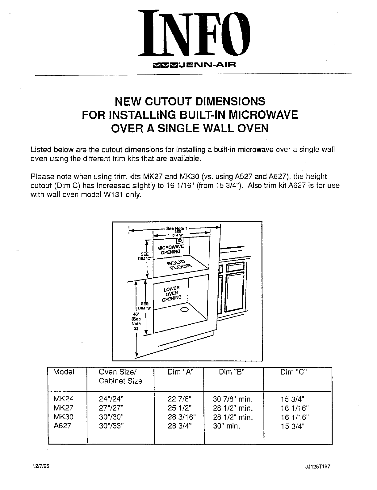
Listed below are the cutout dimensions for installing a built-in microwave over a single wall
oven using the different trim kits that are available.
Please note when using trim kits MK27 and MK30 (vs. using A527 and A627), the height
cutout (Dim C) has increased slightly to 16 1/16" (from 15 3/4"). Alsotrim kitA627 is for use
with wall oven model W131 only.
S OPENING
Model Oven Size/ Dim "A" Dim "B" Dim "C"
Cabinet Size
MK24 24"/24" 22 7/8" 30 7/8" min. 15 3/4"
MK27 27"/27" 25 1/2" 28 1/2" min. 16 1/16"
MK30 30"/30" 28 3/16" 28 1/2" min. 16 1/I6"
A627 30"/33" 28 3/4" 30" min. 15 3/4"
12/7/95 JJ125T197
Page 2
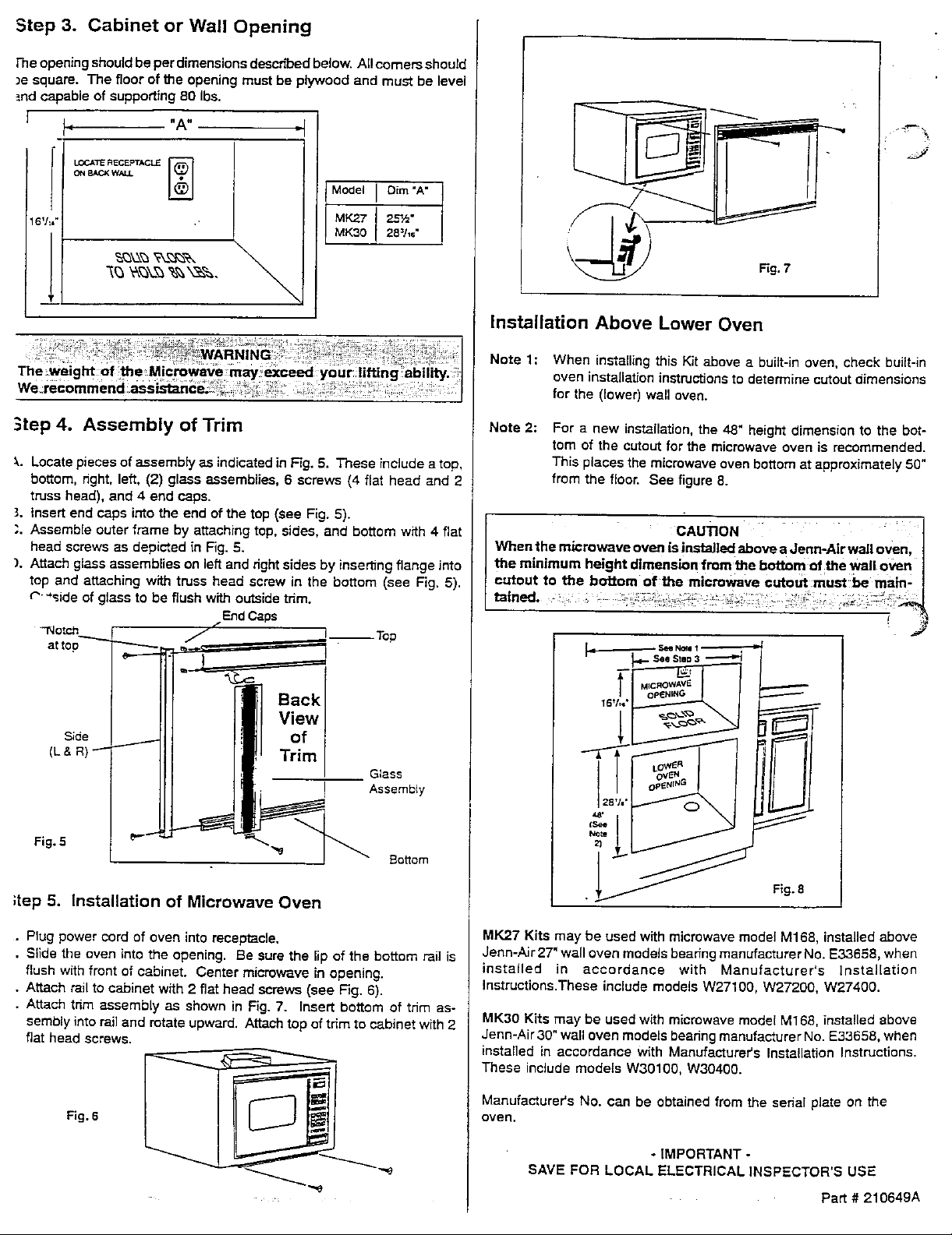
Step 3. Cabinet or Wall Opening
Fneopening should be per dimensions described below. All comers should
_esquare. The floor of the opening must be plywood and must be level
_ndcapable of supporting 80 Ibs.
I j, "A" "1
_TE REC_°TACLE _
8V:
Model I Dim"A"
MK30 28=1,e"
' iv-_
Fig.7
Installation Above Lower Oven
....... Note 1: When installing this Kit above a built-in oven, check built-in
The;weight of _le Microwave oven installafion instmctians to determine cutout dimensions
for the (lower) wall oven.
Step4. Assembly of Trim Note 2: For a new installation, the 48" height dimensfon to the bot-
tom of the Cutout for the microwave oven is recommended.
_.. Locate pieces ofassembly as indicated in Fig. 5. These include a top, This places the microwave oven bottom at approximately 50"
bottom, right, left, (2) glass assemblies, 6 screws (4 fiat head and 2 from the floor. See figure 8.
truss head), and 4 end caps.
3. insert end caps into the end of the top (see Fig. 5).
Assemble
head screws as depicted in Fig. 5. When the microwave oven is installed above a Jenn--Air wall oven, ]
). Attach glass assemblies on left and dght sides by inserting flange into the minimum height dtmenei0n from the bottom of the wall oven
top and attaching with truss head screw in the bottom (see Fig. 5). cutout to the bottom of the microwave cutout:must be main.. I
c'..,side of glass to be flush with outside tdm. rained. ,:: _ _:_ ::"_:_b
outer frame by attaching top, sides, and bottom with 4 fiat CAUTION ' /
EndCaps ................. ........... ": _ "" :i -'_'_.
1
attco e,---- =_ _.-S.eSt.D3 --_'I I
Ill' Trim I f t I I I#11
Fig. 5 _e J _ Bottom
;top5. Installation of Microwave Oven
• Plug power cord of oven into receptacle. MK2.7 Kits may be used with microwave model M168, installed above
• Slide the oven into the opening. Be sure the lip of the bottom rail is Jenn-AJr 27" wall oven models beadng manufacturer No. E33658, when
flush with front of cabinet• Center microwave in opening, installed in accordance with Manufacturer's ]nstal[ation
• Attach rail to cabinet with 2 fiat head screws (see Fig. 6). Instructions.These include models W27100, W27200, W27400.
• Attach tnm assembly as shown in Fig. 7. Insert bottom of tnm as-
sembly into rail and rotate upward. Attach top of trim to cabinet with 2 MK30 Kite may be used with microwave model M168, installed above
flat head screws. Jenn-Air 30" wall oven models beadng manufacturer No. E33658, when
These include modets W30100, W30400.
Fig. 6 oven.
Manufacturer's No. can be obtained from the sedal plate on the
- IMPORTANT -
"._ SAVE FOR LOCAL ELECTRICAL INSPECTOR'S USE
__ installed in accordance with Manufacturers Installation Instructions.
•_ Part # 210649A
Page 3

INSTALLATION
INSTRUCTIONS
PART NO. 210649
Microwave Oven
Built-In Kit
With use of Model M168 Microwave oven.
A. Removetop brackets and discard
(retain screws - see Fig. 2).
Note: A 27" minimum wide
cabinetmustbeprovided B. Replace large bracket withbracket includedin trim kiL
toinstallTrimKitMK27. attaching with screw removed from orJgJnaJ(see Fig. 3).
Note; A 30" minimum wide C. Set microwave on its back so bottom is accessible. Remove
cabinetmustbeprovided leftoutboard screw and corresponding right hand screw from
toinstallTdmKitMK30. bottomfront and attach bottom rail as shownin Figure 4with
Step 2. Bottom Rail
Same screws.
f! f ftT
Step 1. Electrical Requirements ___._____
A. A 120-Volt, 60Hz, AC, 15 ampere, fused electrical supply is
required (time*delayfuse or cimuit breaker is recommended.)
However, if your home has a cimuit wired and fused for 20
amperes, this ispreferred. If you are installinga new cimuit,
OBSERVE ALL GOVERNING CODES AND ORDINANCES. _ Fig. 2
_e wired and fused for 20 amperes is recommended. It is
aiso recommendedthat aseparatecircuitservingonlythis ap-
piiance be provided. Do net use an extensioncord.
B. Electrical Connection t
DO NOT, UNDER ANY CIRCUMSTANCES, REMOVE THE
POWER SUPPLY CORD GROUND PRONG.
ELECTRICAL GROUNDIS REQUIRED ONTHISAPPLIANCE. ",_
For your personal safety, this appliance must be properly _1
power supply cord having a 3-prong grounding plug. To mini-
grounded and polarized. This appliance is equipped with a _J Fig. 3
mize possib[e shock hazard, the cord mustbe pluggedinto a | _ I _.....J J._'ll
mating 3-hole grounding type wall receptacle, grounded in as-
cordance with the National _:}ectricaiCode, Ioca_codes and
ordinances. If a mating wall receptacle is not available, it is ----.._
the personal responsibility and obligation of the customer to
have a propedy grounded and polarized 3-hole wall receptacle
installed by a qualified electrician. (See Figure 1.)
/
L
3-Prong
GroundingF
Ill O)l
PowerSupply -_ r_ //
Co_ _ __ . _-
3-HcJle _mur_ing _'_ _" _ :
Fig.
1
Required Grounding Method
"ry_ew=_ae_pt,_e Fig. 4 "_ i;'"
IU 0}] _"
_ , ; .
<?,
 Loading...