

Jenn-Air 8181P367-60 Installation Manual
INSTALLER: LEAVE THESE INSTRUCTIONS WITH THE APPLIANCE
INSTALLATION MANUAL
Dual-Fuel 30-inch Wide
Jenn-Air Downdraft Range
PLEASE KEEP THIS MANUAL FOR FUTURE REFERENCE
THEMANUALIS INTENDEDTOASSISTIN THEINITIALINSTALLATIONANDADJUSTMENTSOF THERANGE.
CLEARANCEDIMENSIONS
SPECIAL WARNING
Forcompleteinformationinregardto installationof
Only qualified personnel should Jenn-Airrange,seefigures1,2, 3and4. ForSAFETY
install or service this range. CONSIDERATIONS,donotinstalla rangeinany
combustiblecabinetrywhichisnotin accordwiththe
installationclearancesshowninfigure1.
Read "Safety Instructions"in Use&
Care book beforeusingrange.
CAUTION: This rangehasbeendesignedin
accordancewiththe requirementsofvarioussafety
Improper installation, adjustment, agenciesand complieswiththe maximumallowable
alteration, service, maintenance or woodcabinettemperaturesof 194°F. Ifthisrange
isinstalledwithcabinetsthathavea lowerworking
use of range can result in serious temperaturethan 194°F,discoloration,delamination
injury or property damage, ormeltingmay occur.
WARNING I
I ALL RANGES CAN TIP ANDI
CAUSEINJURIESTOPERSONS.
i INSTALL ANTI-TIP DEVICESI
PACKEDWITHRANGE. I ENGLISH ' PP. 1-16
i FOLLOWALLINSTALLATIONIN-J ESPANOL ' p:_g.17-32
STRUCTIONS. I FRANCAIS ' p. 3348
8101P367-60
(12-2000-00)
MAYFAG C0 M
Bring innovation home,t
JENN-AIR RANGES
30"
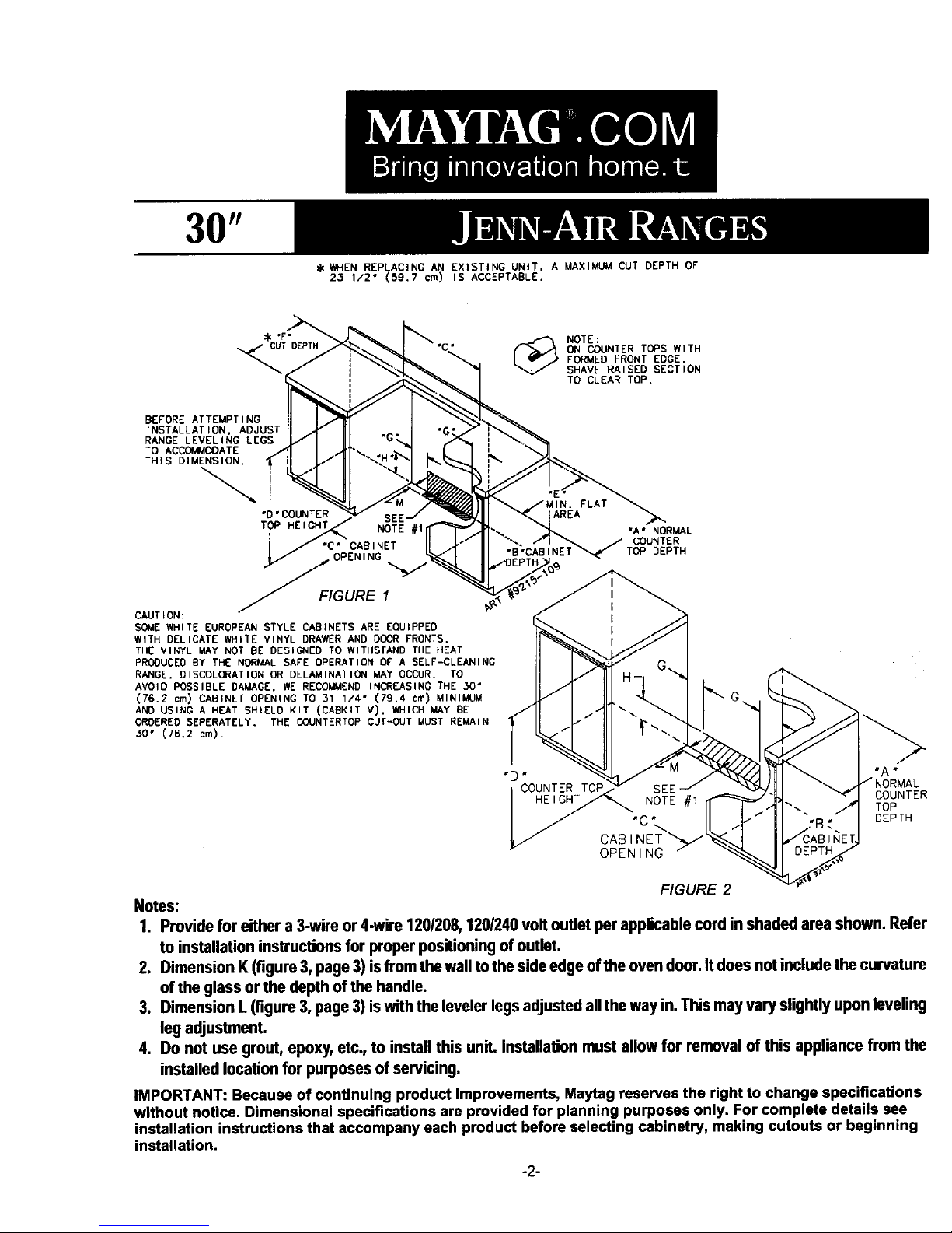
_ WHEN REPLACING AN EXISTING UNIT, A MAXIMUM CUT DEPTH OF
23 1/2" (59.7 cm) IS ACCEPTABLE.
_'F" _ NOTE:
UT DEPTH ON COUNTER TOPS WITH
i SHAVE RAISED SECTION
FORMED FRONT EDGE.
TO CLEAR TOP.
BEFORE ATTEMPT ING
INSTALLATION, ADJUST
RANGE LEVEL ING LEGS
TO ACCOM_IOOATE
THIS DIMENSION,
FLAT
"D" COUNTER AREA
TOP HEIGHT NOTE #1 "A ° NORMAL
. , _ / COUNTER
"C" CAB INET "B "CAB INET_ TOP DEPTH
OPENING
__FIGURE 1 i
CAUT ION : I
SOME WHITE EUROPEAN STYLE CABINETS ARE EQUIPPED I
WITH DELICATE WHITE VINYL DRAWERAND DOOR FRONTS.
THE VINYL MAY NOT BE DESIGNED TO WITHSTAND THE HEAT
PRODUCEDBY THE NORMAL SAFE OPERATION OF A SELF-CLEANING
RANGE. DISCOLORATION OR DELAMINATION MAY OCCUR. TO
AVOID POSSIBLE DAMAGE. WE RECOMMEND INCREASING THE 30 °
(76.2 cm) CABINET OPENING TO 31 1/4" (79.4 cm) MINIMUM
AND USING A HEAT SHIELD KIT (CABKIT V). WHICH MAY BE
ORDERED3o,(76,2SEPERATELY'cm). THE OOUNTERTQP CUT-OUT MUST REMAIN _-,.,...
../"
"D" "A"
COUNTER SEE COUNTER
HEIGHT NOTE #1 " '... TOP
"C " DEPTH
CABINET'_",_/
OPENING /
FIGURE2
Notes:
1. Providefor eithera3-wireor4-wire1201208,1201240voltoutletperapplicablecordinshadedareashown.Refer
toinstallationinstructionsfor properpositioningofoutlet.
2. DimensionK(figure3,page3)isfromthewalltothesideedgeoftheovendoor.Itdoesnotincludethecurvature
ofthe glassorthedepthofthehandle.
3. DimensionL(figure 3, page 3) is withthe levelerI_ls adjusted allthe way in.This may varyslightly upon leveling
legadjustment.
4. Do notusegrout,epoxy,etc.,toinstallthisunit.Installationmustallowfor removalof thisappliancefromthe
installedlocationfor purposesof servicing.
IMPORTANT:Becauseof continuingproductimprovements,Maytagreservestherightto changespecifications
withoutnotice.Dimensionalspecificationsare providedforplanningpurposesonly.Forcompletedetailssee
installationinstructionsthataccompanyeachproductbeforeselectingcabinetry,makingcutoutsorbeginning
installation.
-2-
MAY[AG. C0 M
Bring innovation home.t
JENN-AIR RANGES
30"
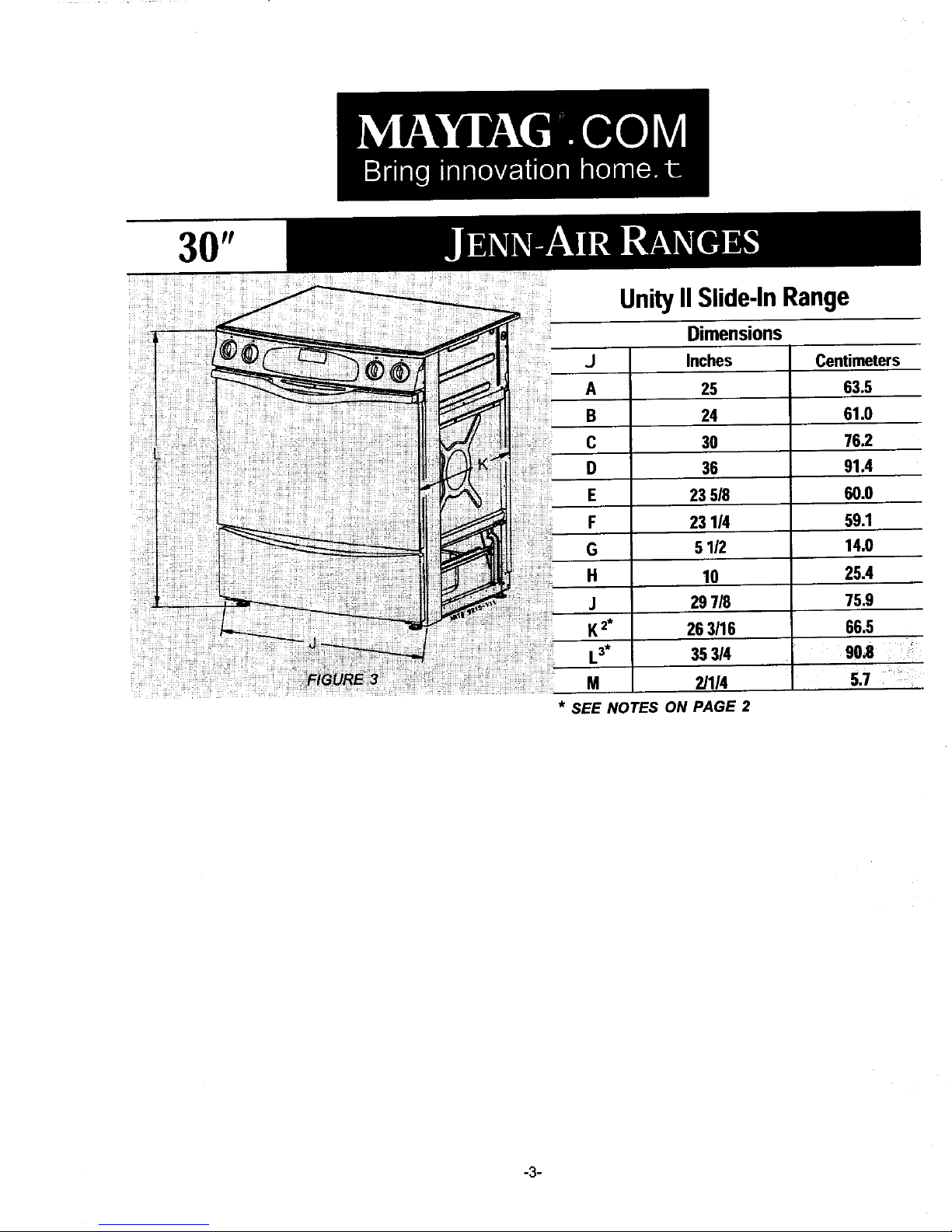
UnityIISlide-InRange
Dimensions
J Inches Centimeters
A 25 63.5
B 24 61.0
C 30 76.2
D 36 91.4
E 235/8 60.0
F 231/4 59.1
G 5 112 14,0
H 10 25.4
297/8 75.9
263/16 66.5
La* 35314 90,8 "
M 2/114 5.7 "_
* SEE NOTES ON PAGE 2
-3-
FIGURE 4
Dimension"A" isto be a minimumof 3-inches (7.5 cm). RECREATIONAL VEHICLES
The installationof a rangedesignedfor recreational
Checkthe rangemodelnumberplatetosee ifthe rangeis vehiclesmustconformwithstateor othercodesor, inthe
approvedfor installationinmobilehomesand/or absenceof suchcodes,withthe Standardfor
recreationalvehicles.If approvedthefollowingitemsare RecreationalVehicles,ANSI A119.2-latest edition.
applicable.
In Canadathe rangemustbe installedinaccordancewith
MOBILE HOMES CAN/CSA - Z240.6.2 - ElectricalRequirementsfor R.V.'s
The installationof arangedesignedfor mobilehome (CSA StandardCAN/CSA - Z240 RV Series)and Section
installationmustconformwith the ManufacturedHome Z240.4.2 - installationRequirementsfor Propane
Constructionand Safety Standard,Title 24 CFR, Part Appliancesand EquipmentinR.V.'s (CSA Standard
3280 [formerlythe Federal Standardfor MobileHome CAN/CSA - Z240 RV Series).
Constructionand Safety, Title 24 HUD, (Part 280)] or,
whensuchstandardisnotapplicable,the Standardfor LOCATING THE RANGE
Manufactured Homeinstallations,ANSI A225.1/NFPA Do notset rangeover holesinthe flooror otherlocations
501A, orwith localcodes, where it maybe subjectto strongdrafts.Any openingin
thewall behindthe rangeandin thefloorunderthe range
In Canadathe rangemustbe installedinaccordancewith shouldbesealed.Make surethe flow of combustionor
the currentCSA StandardC22.1 - CanadianElectrical ventilationair isnotobstructed.
Code Part 1 and SectionZ240.4.1 - Installation
Requirementsfor Gas BurningAppliancesin Mobile NOTE: A range shouldNOT be installedover kitchen
Homes(CSA StandardCAN/CSA - Z240MH). carpeting.
-4 _
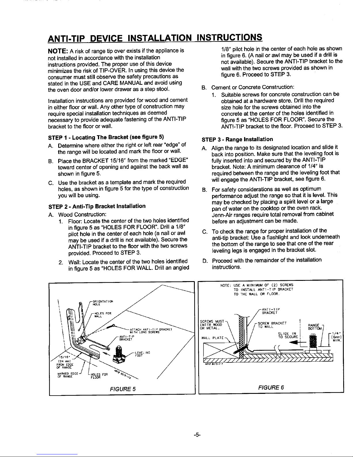
ANTI-TIP DEVICE INSTALLATION INSTRUCTIONS
NOTE: A riskof rangetip overexistsifthe applianceis 1/8" pilotholeinthe centerofeach holeas shown
notinstalledin accordancewiththe installation infigure6. (A nail or awl may be usedif e drillis
instructionsprovided.Theproper useof thisdevice notavailable),SecuretheANTI-TIP brackettothe
minimizesthe riskofTIP-OVER. In usingthisdevicethe wallwiththe twoscrews providedas shown in
consumermuststillobservethesafety precautionsas figure6. Proceedto STEP 3.
statedin the USE and CARE MANUAL andavoidusing
theoven doorand/orlowerdrawer as a stepstool. B. Cement orConcreteConstruction:
1. Suitablescrewsforconcreteconstructioncan be
Installationinstructionsare providedfor woodandcement obtainedat a hardwarestore. Drillthe required
in eitherfloororwall.Anyother type ofconstructionmay sizeholeforthescrews obtainedintothe
requirespecialinstallationtechniquesas deemed concreteat the centerofthe holesidentifiedin
necessaryto provideadequatefasteningofthe ANTI-TIP figure5 as "HOLES FOR FLOOR'. Securethe
bracketto thefloororwall. ANTI-TIP bracketto thefloor. Proceedto STEP 3,
STEP 1 - Locating The Bracket (see figure 5) STEP 3 - Range Installation
A. Determinewhere either the right or left rear "edge" of
the range will be located and markthe floor or wall. A. Align the range to its designated location and slide it
back into position. Make sure that the leveling foot is
B. Place the BRACKET 15/16" from the marked "EDGE" fully inserted into and secured by the ANTI-TIP
toward center of opening and against the backwall as bracket. Note: A minimum clearance of 114"is
shown in figure 5. required between the range and the leveling foot that
C. Use the bracket as a template and mark the required will engage the ANTI-TIP bracket, see figure 6.
holes, as shown in figure 5 for the type of construction B. For safety considerations as well as optimum
you will be using, performanceadjust the range so that it is level. This
may be checked by placing a spirit level or a large
STEP 2 - Anti-Tip Bracket Installation panof wateron the cooktopor the ovenrack.
A. WoodConstruction: Jenn-Airrangesrequiretotal removalfrom cabinet
1. Floor:Locatethe centerofthe two holesidentified beforean adjustmentcan bemade.
infigure5 as "HOLES FOR FLOOR". Drilla 1/8"
pilotholeinthe centerof each hole(a nailor awl C. To checkthe rangefor properinstallationof the
may be usedif a drillisnotavailable).Securethe anti-tipbracket:Use a flashlightand look underneath
ANTI-TIP bracketto thefloorwiththe twoscrews the bottomofthe rangeto see thatone of the rear
provided.Proceedto STEP 3. levelinglegsis engagedinthe bracketslot.
2. Wall: Locatethe centerof the twoholesidentified D. Proceedwiththe remainderofthe installation
in figure5 as "HOLES FOR WALL. Ddllan angled instructions.
NOTE; USE A MINIMUM OF" (2) SCREWS
TO INSTALL ANTI-TIP BRACKET
TO THE WALL OR FLOOR.
_ O_1ENTATIO1_
HOLE
,
t HOLESFOR / BRACKET
;CREWS MUST
ENTER WOOD SCREW BRACKET RANGE
OR METAL, TO WALL BOTTOM
iiii '
.......... - SL,OE.N .7 .1,,"
t BRACKET W TO SECURE [6mm]
/ E=.._ _ [ _ _ / ////////J" "///////////////////J
OF RANGE
_]_RK_GEDGE HOLES FOR _'_"l
FL00
FIGURE 5 FIGURE 6
-5-
 Loading...