

Jenn-Air 8101P427 Installation Manual
INSTALLER: LEAVE THESE INSTRUCTIONS WITH THE APPLIANCE
INSTALLATION MANUAL
Electric 30-inch Wide
Jenn-Air Downdraft Range
PLEASE KEEP THIS MANUAL FOR FUTURE REFERENCE
THE MANUAL IS INTENDED TO ASSIST IN THE INITIAL INSTALLATION AND ADJUSTMENTS OF THE RANGE.
CLEARANCEDIMENSIONS
SPECIAL WARNING
For complete information in regard to installationof
Onlyqualified personnelshould Jenn-Air range, see figures 1,2, 3and 4. For SAFETY
installor servicethis range. CONSIDERATIONS, do not installa range in any
combustiblecabinetrywhichis notinaccordwiththe
installationclearancesshowninfigure 1.
Read "Safety Instructions" in Use&
Care bookbefore usingrange. CAUTION: This range has been designedin
accordancewith the requirementsof various safety
Improper installation, adjustment, agencies and complieswith the maximum allowable
wood cabinet temperaturesof 194°F. If this range
alteration, service, maintenance or is installedwith cabinets that have a lower working
use of range can result in serious temperature than 194°F, discoloration,delamination
or meltingmay occur.
injury or property damage.
Your range may notbe equipped I
WARNING w,th some of the features referred I
). ALALusRA;GERSIEsCA;pT/RPsoANsD, to in this manual, I
• INSTALL ANTI-TIP DEVICES
PACKED WITH RANGE.
ENGLISH I_ PP. 1-11
• FOLLOW ALL INSTALLATION ESPAI;IOL I) pan. 12-22
INSTRUCTIONS. FRANCAIS _ p, 23-33
8101 P427-60
(I0-01-00)
INSTALLATIONDRAWINGS(Pages 2, 3 & 4)
I IMPORTANT
PLEASE KEEP FOR THE USE OF THE-LOCAL ELECTRICAL INSPECTOR.
o_
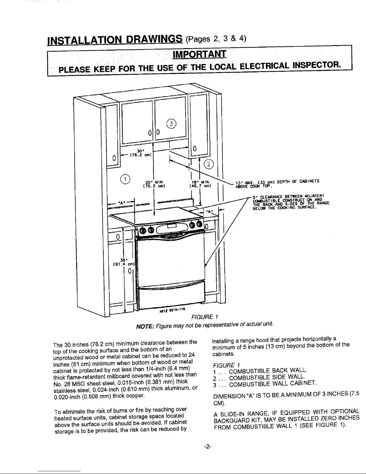
CLEARANCE BETWEEN ,M]JACENT
COMBUSTIBLE COI¢STRUCTIOI_ AriD
TH£ BACK AND SIDe'S OF" THE RANGE
BELOW ,HE COOKING SURFACE.
_ql# 92_f>'l ts
FIGURE 1
NOTE: Figure may not be representative of actual unit.
The 30 inches (76.2 cm) minimum clearance betweenthe installinga range hoodthat projects horizontally a
top of the cooking surface and the bottom of an minimum of 5 inches (13 cm) beyond the bottom of the
unprotected wood or metal cabinet can be reduced to 24 cabinets.
inches (61 cm) minimum when bottom of wood or metal
cabinet is protected by not less than 1/4-inch (6.4 ram) FIGURE 1
thick flame-retardant millboard covered with not less than 1 ... COMBUSTIBLE BACK WALL.
No. 28 MSG sheet steel, 0.015-inch (0.381 mm) thick 2 ... COMBUSTIBLE SIDE WALL.
stainless steel, 0.024-inch (0.610 ram) thick aluminum, or 3 ... COMBUSTIBLE WALL CABINET.
0.020-inch (0.508 mm) thick copper. DIMENSION "A" IS TO BE A MINIMUM OF 3 iNCHES (7.5
CM).
To eliminate the risk of burns or fire by reaching over
heated surface units, cabinet storage space located A SLIDE-IN RANGE, IF EQUIPPED WITH OPTIONAL
above the surface units should be avoided. If cabinet 8ACKGUARD KIT, MAY BE INSTALLED ZERO INCHES
storage is to be provided, the risk can be reduced by FROM COMBUSTIBLE WALL 1 (SEE FIGURE 1).
-2-
MAY[AG C0 M
Bring innovation home.
30"
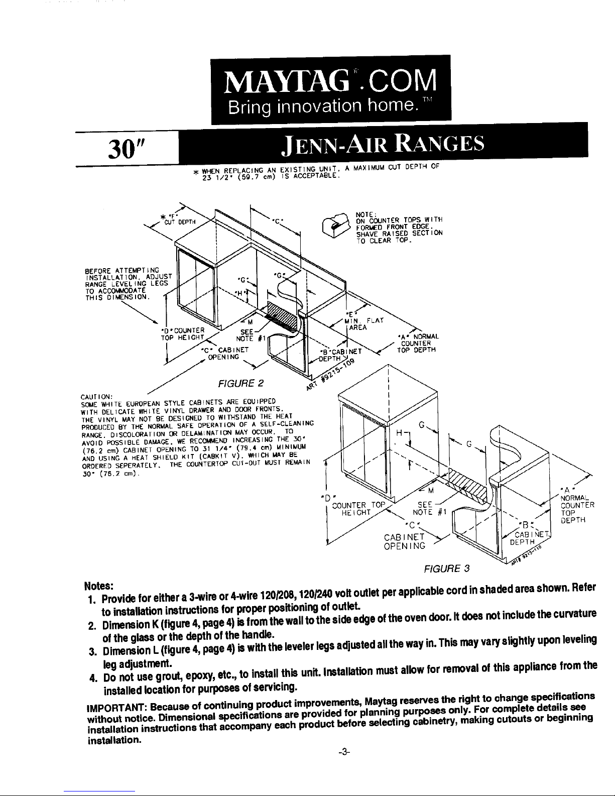
_ WHEN REPLACING AN EXISTING UNIT, A MAXIMUM CUT DEPTH OF
23 1/2" (59.7 cm) IS ACCEPTABLE.
JENN-AIR RANGES
X<"F""nrpT__ p'_ _ NOTE:
._T_ "C__ L_ ON COUNTER TOPS WITH
_, EORMEO FRONT EDGE.
"t SHAVE RAISED SECTION
_. ] TO CLEAR TOP.
BEFOREATTEMPTINGII I _ I __I_-
INSTALLATION, ADJUST I} X }_J - I
RANGE LEVELING LEGS Ib/ I I[I "u:__l
TO ACCOMMODATE A I JH'-. . "I
J °C" CAB INET COUNTER
V /_OPENIN G TOP DEPTH
_- FIGURE 2
CAUTION:
SOME WHITE EUROPEAN STYLE CABINETS ARE EQUIPPED
WITH DELICATE WHITE VINYL DRAWER AND DOOR FRONTS.
THE VINYL MAY NOT BE DESIGNED TO WITHSTAND THE HEAT
PRODUCED BY THE NORMAL SAFE OPERATION OF A SELF-CLEANING
AVOID POSSIBLE DAMAGE, WE RECOMMEND INCREASING THE 30"
(76.2 cm) CABINET OPENING TO 31 1/4" (79.4 cm) MINIMUM G
AND USING A HEAT SHIELD KIT {CABXIT V), WHICH MAY BE
ORDERED SEPERATELY. THE COUNTER'fOP CUI-OUT MUST REMAIN
30" {76.2 cm).
m
C "B"
FIGURE 3
Notes:
1. Provideforeithera3-wireor4.wire120/208,120/240voltoutletperapplicablecordinshadedareashown.Refer
toinstallationinstructionsforproperpositioningofoutlet.
2. DimensionK(figure4,page4)isfromthewalltothesideedgeoftheovendoor.Itdoesnotincludethecurvature
oftheglassorthedepthofthehandle.
3. DimensionL(figure4,page4)iswiththelevelerlegsadjustedallthewayin.Thismayvaryslightlyuponleveling
legadjustment.
4. Donotusegrout,epoxy,etc.,toinstallthisunit.Installationmustallowforremovalof thisappliancefromthe
installedlocationforpurposesofservicing.
IMPORTANT:BecauseofconUnuingproductimprovements,Maylagreserves therightto change specifications
withoutnotice.Dimensionalspecificationsareprovidedforplanningpurposesonly.Forcompletedetailssee
installationinstruCtionsthataccompanyeachproduCtbeforeselectingcabinetry,makingcutoutsorbeginning
installation.
-3-
 Loading...