

Jenn Air 720-0720 Owner's Manual

JENN-AIR® FREESTANDING OUTDOOR GRILLS
ASADORES A UTÓNOMOS P ARA EXTERIORES
JENN-AIR
®
GRILS D’EXTÉRIEUR A UTOPORTANTS JENN-AIR
®
Installation Instructions and Use & Care Guide
For questions about features , operation/performa nce, parts, acc essories, or service, ca ll:
1-800-554-5799
Instrucciones de instalación y Manual de uso y cuidado
Para consultas re specto a c aracteríst icas, funci onamiento, rendimiento, piezas, acce sorios o s ervicio téc nico, llame al:
1-800-554-5799
Instructions d’installation et Guide d’utilisation et d’entretien
Au Canada, pour ass istance, install ation ou serv ice, comp osez le
1-800-554-5799.
720-0720 (LP) 730-0720 (NG)
IMPORTANT:
Save for local electrical inspector's use.
Installer: Leave installation instructions with the homeowner.
Homeowner: Keep installation instructions for future reference.
IMPORTANTE:
Guarde para tenerlas a disposición del inspector de electricidad local.
Instalador: Deje las instrucciones de instalación con el propietario.
Propietario: Conserve las instrucciones de instalación para referencia futura.
IMPORTANT :
Conserver pour consultation par l'inspecteur local des installations électriques.
Installateur : Remettre les instructions d'installation au propriétaire.
Propriétaire : Conserver les instructions d'installation pour référence ultérieure.
T able of Contents /Índice/Table des matières .................. ..2

T ABLE OF CONTENTS
OUTDOOR GRILL SAFETY ...........................................................3
INSTALLATION REQUIREMENTS................................................5
Tools and Parts............................................................................5
Location Requirements................................................................5
Product Dimensions ....................................................................6
Electrical Requirements...............................................................6
Gas Supply Requirements...........................................................7
Gas Connection Requirements....................................................8
INSTALLATION INSTRUCTIONS..................................................9
Freestanding Outdoor Grill Installation ........................................9
Make Gas Connection................................................................12
GAS CONVERSIONS ...................................................................14
Tools and Parts for Gas Conversion..........................................14
Conversion from LP Gas to Natural Gas...................................14
Check and Adjust the Burners...................................................18
OUTDOOR GRILL USE................................................................19
Using Your Outdoor Grill............................................................19
ÍNDICE
SEGURIDAD DEL ASADOR PARA EXTERIORES....................35
REQUISITOS DE INSTALACIÓN.................................................37
Herramientas y piezas................................................................37
Requisitos de ubicación.............................................................37
Medidas del producto.................................................................38
Requisitos eléctricos ..................................................................38
Requisitos del suministro de gas...............................................39
Requisitos para la conexión de gas...........................................40
INSTRUCCIONES DE INSTALACIÓN.........................................41
Instalación del asador autónomo para exteriores......................41
Conexión del suministro de gas.................................................44
CONVERSIONES DE GAS...........................................................46
Herramientas y piezas para la conversión de gas.....................46
Conversión de gas LP a gas natural..........................................46
Revise y regule los quemadores................................................50
USO DEL ASADOR PARA EXTERIORES ..................................52
Cómo usar el asador para exteriores.........................................52
Luces de la capota.....................................................................54
Hood Lights.................................................................................20
Using Your Searing Side Burner................................................21
Using Your Rotisserie Burner.....................................................22
Rotisserie Cooking Tips .............................................................22
Using the Side Shelf Timer.........................................................23
TIPS FOR OUTDOOR GRILLING.................................................24
Cooking Methods........................................................................24
Grilling Chart...............................................................................25
OUTDOOR GRILL CARE..............................................................27
Replacing the Igniter Battery......................................................27
Changing the Light Bulb.............................................................27
General Cleaning........................................................................28
TROUBLESHOOTING ..................................................................30
ASSISTANCE................................................................................30
Accessories................................................................................30
REPLACEMENT PARTS ..............................................................31
WARRANTY ..................................................................................34
Cómo usar el quemador lateral para dorado rápido..................54
Cómo usar el quemador del rostizador......................................55
Consejos para la cocción con el rostizador ...............................56
Cómo usar el temporizador del estante lateral..........................57
CONSEJOS PARA ASAR AL AIRE LIBRE.................................57
Métodos de cocción....................................................................57
Cuadro para asar........................................................................58
CUIDADO DEL ASADOR PARA EXTERIORES .........................60
Cómo reemplazar la batería del encendedor.............................60
Cómo cambiar el foco ................................................................61
Limpieza general........................................................................62
SOLUCIÓN DE PROBLEMAS......................................................64
ASISTENCIA..................................................................................64
Accesorios..................................................................................64
PIEZAS DE REPUESTO...............................................................65
GARANTÍA ....................................................................................67
TABLE DES MA TIÈRES
SÉCURITÉ DU GRIL D'EXTÉRIEUR ...........................................69
EXIGENCES D’INSTALLATION...................................................71
Outils et pièces...........................................................................71
Exigences d'emplacement.........................................................71
Dimensions du produit................................................................72
Spécifications électriques...........................................................72
Spécifications de l'alimentation en gaz......................................73
Exigences concernant le raccordement au gaz.........................73
INSTRUCTIONS D’INSTALLATION ............................................74
Installation du gril d’extérieur autoportant..................................74
Raccordement au gaz................................................................77
CONVERSIONS POUR CHANGEMENT DE GAZ.......................80
Outils et pièces pour conversion de gaz....................................80
Conversion de propane à gaz naturel........................................80
Contrôle et réglage des brûleurs................................................84
UTILISATION DU GRIL D’EXTÉRIEUR.......................................86
Utilisation du gril d’extérieur.......................................................86
Lampes sous le couvercle..........................................................88
2
Utilisation du brûleur à rôtissage latéral.....................................88
Utilisation du brûleur de tournebroche.......................................89
Conseils de cuisson à l’aide du tournebroche...........................90
Utilisation de la minuterie de tablette latérale............................91
CONSEILS POUR L'UTILISATION DU GRIL D'EXTÉRIEUR ....91
Méthodes de cuisson .................................................................91
Tableau de cuisson au gril .........................................................92
ENTRETIEN DU GRIL D’EXTÉRIEUR .........................................95
Remplacement de la pile de l’allumeur......................................95
Changement de l’ampoule d’éclairage.......................................95
Nettoyage général......................................................................96
DÉPANNAGE ................................................................................98
ASSISTANCE................................................................................99
Accessoires................................................................................99
PIÈCES DE RECHANGE............................................................100
GARANTIE...................................................................................103
OUTDOOR GRILL SAFETY
You can be killed or seriously injured if you don't immediately
You
can be killed or seriously injured if you don't
follow
All safety messages will tell you what the potential hazard is, tell you how to reduce the chance of injury, and tell you what can
happen if the instructions are not followed.
Your safety and the safety of others are very important.
We have provided many important safety messages in this manual and on your appliance. Always read and obey all safety
messages.
This is the safety alert symbol.
This symbol alerts you to potential hazards that can kill or hurt you and others.
All safety messages will follow the safety alert symbol and either the word “DANGER” or “WARNING.”
These words mean:
follow instructions.
instructions.
DANGER
WARNING
If you smell gas:
1. Shut off gas to the appliance.
2. Extinguish any open flame.
3. Open lid.
4. If odor continues, keep away from the
appliance and immediately call your
gas supplier or your fire department.
DANGER
WARNING
1. Do not store or use gasoline or other
flammable liquids or vapors in the
vicinity of this or any other appliance.
2. An LP cylinder not connected for use
shall not be stored in the vicinity of
this or any other appliance.
State of California Proposition 65 Warnings:
WARNING: This product contains a chemical known to the State of California to cause cancer.
WARNING: This product contains a chemical known to the State of California to cause birth defects or other reproductive harm.
In the State of Massachusetts, the following installation instructions apply:
■ Installations and repairs must be performed by a qualified or licensed contractor, plumber, or gasfitter qualified or licensed by
the State of Massachusetts.
■ If using a ball valve, it shall be a T-handle type.
■ A flexible gas connector, when used, must not exceed 3 feet.
IMPORTANT: This grill is manufactured for outdoor use only. For grills that are to be used at elevations above 2000 ft (609.6 m) orifice
conversion is required. See “Gas Supply Requirements” section. It is the responsibility of the installer to comply with the minimum
installation clearances specified on the model/serial rating plate. The model/serial rating plate for freestanding models can be found on
the right-hand inside cabinet wall.
3
SAVE THESE INSTRUCTIONS
IMPORTANT SAFETY INSTRUCTIONS
WARNING: To reduce the risk of fire, electrical shock,
injury to persons, or damage when using the outdoor cooking
gas appliance, follow basic precautions, including the
following:
■ Do not install portable or built-in outdoor cooking gas
appliances in or on a recreational vehicle, portable trailer,
boat or in any other moving installation.
■ Always maintain minimum clearances from combustible
construction, see “Location Requirements” section.
■ The outdoor cooking gas appliance shall not be located
under overhead unprotected combustible construction.
■ This outdoor cooking gas appliance shall be used only
outdoors and shall not be used in a building, garage, or any
other enclosed area.
■ Keep any electrical supply cord and fuel supply hose away
from any heated surfaces.
■ Keep outdoor cooking gas appliance area clear and free
from combustible materials, gasoline and other flammable
vapors and liquids.
■ Do not obstruct the flow of combustion and ventilation air.
Keep the ventilation openings of the cylinder enclosure free
and clear from debris.
■ Open the cabinet door and inspect the gas cylinder supply
hose before each use of the outdoor cooking gas
appliance. If the hose shows excessive abrasion or wear,
or is cut, it MUST be replaced before using the outdoor
cooking gas appliance. Contact your dealer and use only
replacement hoses specified for use with the outdoor
cooking gas appliance.
■ Visually check the burner flames.
They should be blue. Slight
yellow tipping is normal for LP
gas. The flames should be
approximately 1" (2.5 cm) high.
■ Check and clean burner/venturi tube for insects and insect
nest. A clogged tube can lead to fire under the outdoor
cooking gas appliance.
■ The LP gas supply cylinder to be used must be:
- constructed and marked in accordance with the
Specification for LP Gas Cylinders of the U.S. Department
of Transportation (DOT) or the National Standard of
Canada, CAN/CSA-B339, Cylinders, Spheres, and Tubes
for Transportation of Dangerous Goods; and Commission.
- provided with a listed overfilling prevention device.
- provided with a cylinder connection device compatible
with the connection for outdoor cooking gas appliances.
■ Always check connections for leaks each time you connect
and disconnect the LP gas supply cylinder. See
“Installation Instructions” section.
■ When the outdoor cooking gas appliance is not in use, the
gas must be turned off at the supply cylinder.
■ Storage of an outdoor cooking gas appliance indoors is
permissible only if the cylinder is disconnected and
removed from the outdoor cooking gas appliance.
■ Cylinders must be stored outdoors and out of the reach of
children and must not be stored in a building, garage, or
any other enclosed area.
■ The pressure regulator and hose assembly supplied with
the outdoor cooking gas appliance must be used. A
replacement pressure regulator and hose assembly
specific to your model is available from your outdoor
cooking gas appliance dealer.
■ Gas cylinder must include a collar to protect the cylinder
valve.
■ For appliances designed to use a CGA791 Connection:
Place a dust cap on cylinder valve outlet whenever the
cylinder is not in use. Only install the type of dust cap on
the cylinder valve outlet that is provided with the cylinder
valve. Other types of caps or plugs may result in leakage
of propane.
If the following information is not followed exactly, a fire
causing death or serious injury may occur.
■ Do not store a spare LP gas cylinder under or near this
outdoor cooking gas appliance.
■ Never fill the cylinder beyond 80 percent full.
1"
(2.5 cm)
4
INSTALLA TION REQUIREMENTS
WARNING
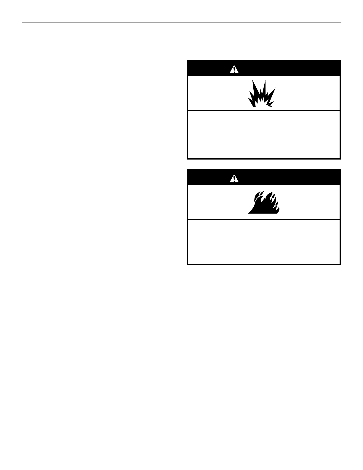
Explosion Hazard
Do not store fuel tank in a garage or indoors.
Do not store grill with fuel tank in a garage or indoors.
Failure to follow these instructions can result in death,
explosion, or fire.
WARNING
Fire Hazard
Do not use grill near combustible materials.
Do not store combustible materials near grill.
Doing so can result in death or fire.
T ools and Parts
Gather the required tools and parts before starting installation.
Read and follow the instructions provided with any tools listed
here.
T ool s Neede d
■ Phillips screwdriver
■ Wrench or pliers
■ Pipe wrench
Parts Supplied
■ Gas pressure regulator/hose assembly set for 11" WCP LP
gas
■ Right side shelf with sear burner
■ Left side shelf
■ Side shelf push bar
■ Side shelf push bar seat (2)
■ Control knob (1)
■ Grill cover
■ “AA” Batteries (3)
■ Warming rack
■ Cooking grid
■ Side burner cooking grid
■ Natural gas orifice for rotisserie/infrared burner
■ Scissors or cutting pliers
(to remove tiedowns)
■ Noncorrosive leak-
detection solution
Location Requirements
Parts Needed
■ 20 lb LP gas fuel tank - approximately 18" (45.7 cm) height
and 12" (30.5 cm) diameter
Parts Needed fo r Conversio n to Nat ural Gas
■ Natural gas conversion kit Part Number 710-0003. See
“Assistance” section to order. The conversion kit includes:
■ Natural gas regulator 4" W.C. (marked “Natural Gas
Regulator”)
■ 10 ft (3.0 m) Natural gas hose with quick connector
■ 5.9" (150 mm) Natural gas regulator hose
■ 6 mm nut driver
■ 6mm wrench
■ Allen key
■ Gas line shutoff valve
■ ½" male pipe thread nipple for connection to pressure
regulator.
■ LP gas-resistant pipe-joint compound
■ CSA design-certified out door fle xible st ain less ste el app lianc e
connector (4-5 ft [1.2-1.5 m]) or rigid gas supply line as
needed.
Select a location that provides minimum exposure to wind and
traffic paths. The location should be away from strong draft areas.
Do not obstruct flow of combustion and ventilation air.
Clearance to combustible construction for freestanding outdoor
grills:
■ A minimum of 24" (61 cm) must be maintained between the
front of the grill hood, sides and back of the grill and any
combustible construction.
■ A 24" (61 cm) minimum clearance must also be maintained
below the cooking surface, and the grill shall not be used
under overhead combustible construction.
Rotisserie (accessory)*
If you equip your grill with a rotisserie, a 6" (15.2 cm) minimum
clearance is needed for the rotisserie motor.
A grounded, 3-prong outlet located to the left of the grill is
required.
*See “Assistance” section to order.
5
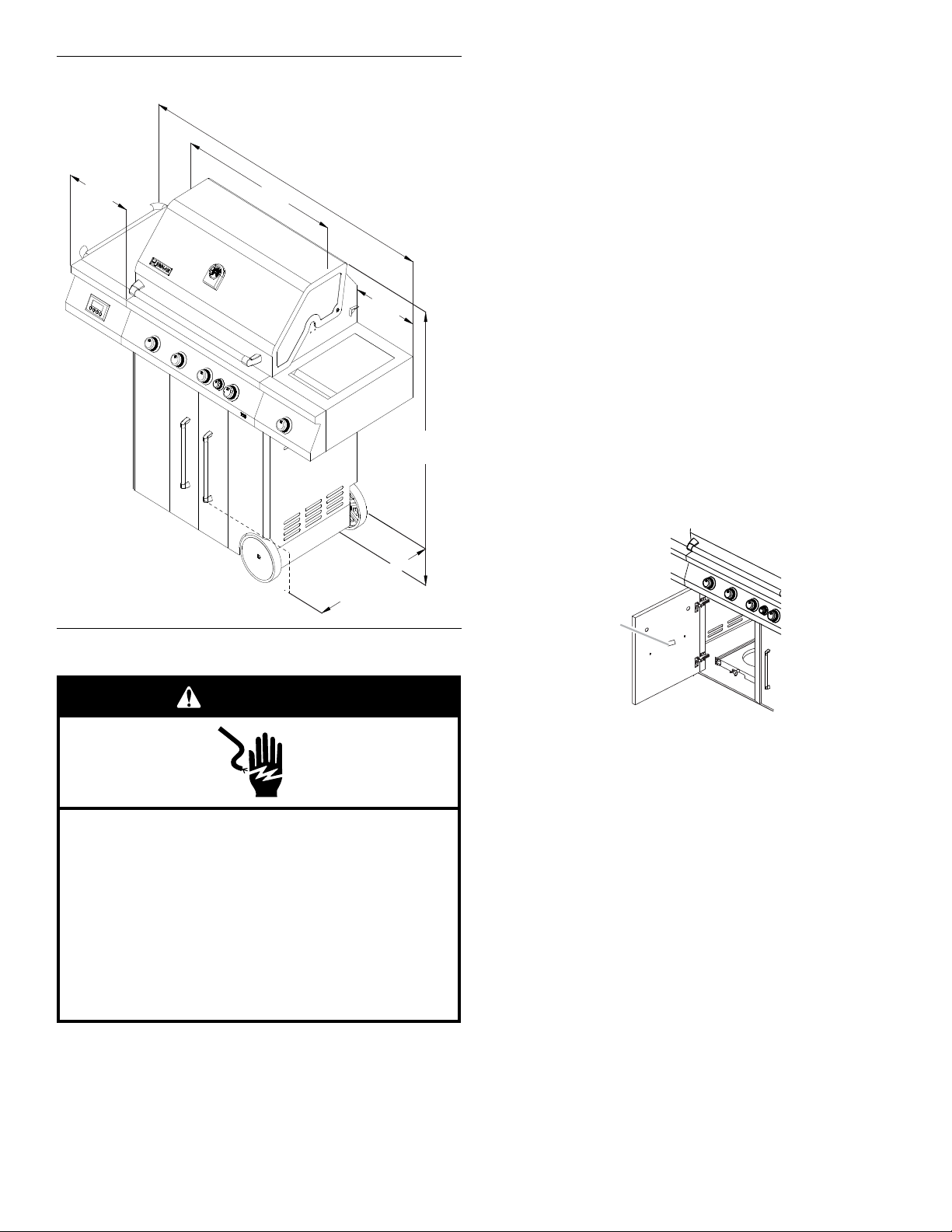
Product Dimensions
22 ⁄ " (58.1 cm)
49³⁄ "
(125.4 cm)
12 ⁄ "
(32 cm)
12 ⁄ "
(32 cm)
59¹⁄ "
(151.1 cm)
31"
(78.7 cm)
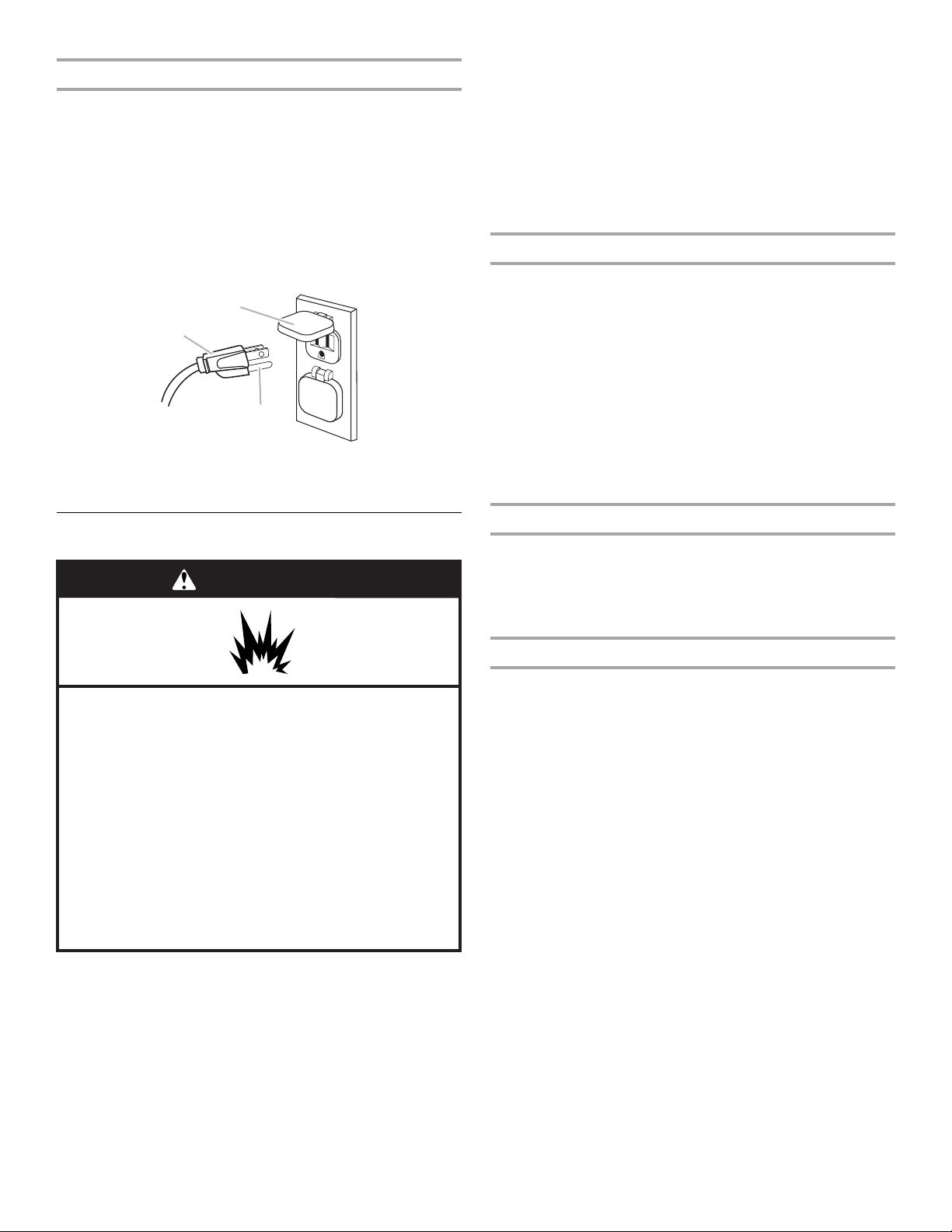
Electrical Shock Hazard
Use only a UL listed, 14 gauge, 3 wire extension cord
approved for outdoor use, marked W-A, with a
maximum length of 50 ft.
Plug into a grounded 3 prong outlet.
Do not remove ground prong.
Do not use an adapter.
Failure to follow these instructions can result in death,
fire, or electrical shock.
WARNING
A
It is recommended that a separate circuit servicing only this grill
be provided.
■ To avoid electrical shock, do not immerse cord or plugs in
water or other liquid.
■ Unplug from the outlet when not in use and before cleaning.
Allow to cool before putting on or taking off parts.
■ Do not operate any outdoor cooking gas appliance with a
damaged cord, damaged plug, or after the appliance
malfunctions or has been damaged in any manner. Contact
the manufacturer for repair.
■ Do not let the cord hang over the edge of a table or touch hot
surfaces.
■ Do not use an outdoor cooking appliance for purposes other
than intended.
■ When connecting, first connect plug to the outdoor cooking
gas appliance then plug appliance into the outlet.
■ Use only a Ground Fault Interrupter (GFI) protected circuit
with this outdoor cooking gas appliance.
■ Do not remove the ground prong or use with an adapter of
2prongs.
■ Use only extension co rds with a 3 prong grounding plu g rate d
for the power of the equipment and approved for outdoor use
with a W-A marking.
The model/serial number rating plate is located on the inside of
the left cabinet door. See the following illustration.
Electrical Requirements
If codes permit and a separate ground wire is used, it is
recommended that a qualified electrician determine that the
ground path is adequate.
Check with a qualified electrician if you are not sure whether the
grill is properly grounded.
A 120-volt, 60-Hz, AC-only, 15-amp, fused electrical sup ply is
required.
6
A. Model/serial number plate
Recommended Ground Method
A
B
C
WARNING
Explosion Hazard
Use a new CSA International approved “outdoor”
gas supply line.
Securely tighten all gas connections.
If connected to LP, have a qualified person make sure
gas pressure does not exceed 11” (28 cm) water
column.
Examples of a qualified person include:
licensed heating personnel,
authorized gas company personnel, and
authorized service personnel.
Failure to do so can result in death, explosion, or fire.
The outdoor grill, when installed, must be electrically grounded in
accordance with local codes or, in the absence of local codes,
with the National Electrical Code ANSI/NFPA 70, or Canadian
Electrical Code, CSA C22.1.
Copies of the standards listed above may be obtained from:
CSA International
8501 East Pleasant Valley Rd.
Cleveland, Ohio 441 31-5 57 5
National Fire Protection Association
One Batterymar ch Park
Quincy, Massachusetts 02269
A. 3-prong ground plug
B. 3-prong polarized type outdoor GFI outlet
C. Ground prong
IMPORTANT: Grill must be connected to a regulated gas supply.
Refer to the model/serial rating plate for information on the type
of gas that can be used. If this information does not agree with
the type of gas available, check with your local gas supplier.
Gas Conversion:
No attempt shall be made to convert the grill from the gas
specified on the model/serial rating plate for use with a different
gas type without consulting the serving gas supplier. The
conversion kit supplied with grill must be used. See “Gas
Conversions” section for instructions.
Gas Pressure Regulator
The gas pressure regulator supplied with this grill must be used.
The inlet (supply) pressure to the regulator should be as follows
for proper operation:
LP Gas:
Operating pressure: 11" (27.9 cm) WCP
Inlet (supply) pressure: 11" to 14" (27.9 cm to 35.5 cm) WCP
Natural Gas:
Operating pressure: 4" (10.2 cm) WCP
Inlet (supply) pressure: 7" to 14" (17.8 cm to 35.5 cm) WCP
maximum.
Contact local gas supplier if you are not sure about the inlet
(supply) pressure.
Gas Supply Requirements
Burner Requirements for High Altitude
Input ratings shown on the model/serial rating plate are for
elevations up to 2,000 ft (609.6 m).
For elevations above 2,000 ft (609.6 m), ratings are reduced at a
rate of 4% for each 1,000 ft (304.8 m) above sea level. Orifice
conversion is required. See “Assistance” section to order.
Gas Supply Line Pressure Testing
Testing above ½ psi (3.5 kPa) or 14" (35.5 cm) WCP (gauge):
The grill and its individual shutoff valve must be disconnected
from the gas supply piping system during any pressure testing of
that system at test pressures greater than ½ psi (3.5 kPa).
T esting below ½ p si (3.5 kPa) or 14" (35.5 cm) WCP (gauge) or
lower:
The grill must be isolated from the gas supply piping system by
closing its individual manual shutoff valve during any pressure
testing of the gas supply piping system at test pressures equal to
or less than ½ psi (3.5 kPa).
Observe all governing codes and ordinances.
IMPORTANT: This installation must conform with all local codes
and ordinances. In the absence of local codes, installation must
conform with either the National Fuel Gas Code, ASNI Z223.1/
NFPA 54, Natural Gas and Propane Installation Code, CSA
B149.1, Propane Storage and Handling Code, B149.2, or the
Stan da rd for R e cre ati ona l Vehicles, ASNI A119 .2/ NFPA 1192 a nd
CSA Z240 RV Series Recreational Vehicle Code as applicable.
7
Gas Connection Requirements
A
A
A
C
B
A
A
B
C
20 lb LP Gas Fuel Tank
This grill is equipped for use with a 20 lb LP gas fuel tank (fuel
tank not supplied). A gas pressure regulator/hose assembly is
supplied.
Any brand of 20lb LP gas fuel tank is acceptable for use with the
grill, provided that it is compatible with the grill’s retention means
(tank tray included).
It is also design-certified by CSA International for local LP gas
supply or for Natural gas with appropriate conversion.
A. Ga s pressure regulator/hose assembly
The 20 lb LP gas fuel tank must be mounted and secured.
Door Style Tank Tray
1. Open cabinet doors.
2. Slide the tank tray locking bracket clockwise 90° and pull out
the tray.
5. Slide the drawer with the 20 lb LP gas fuel tank back into the
cabinet. Turn the tank tray locking bracket counterclockwise
90° to tighten.
A. Tank tray locking bracket
Natural Gas Conversion
Conversion must be made by a qualified gas technician. The
qualified Natural gas technician shall provide the Natural gas
supply to the selected grill locati on in accord an ce w ith the
National Fuel Gas Code ANSI Z223.1/NFPA 54 - latest edition,
and local codes. For conversion to Natural gas, the Natural Gas
Conversion Kit supplied with the grill (on some models) or the
Natural Gas Conversion Kit Part Number W10118098 must be
used. See “Assistance” section for information on ordering.
IMPORTANT: The gas ins t al lation must conform w i th loc al c ode s,
or in the absence of local codes, with the N ational Fu el Gas Code,
ANSI Z223.1/NFPA 54 - latest edition.
Follow instructions for converting to Natural gas in the “Gas
Conversions” section of this manual or the instructions supplied
with Natural Gas Conversion Kit Part Number 710-0003.
The gas supply line shall be equipped with an approved shutoff
valve. This valve should be located in the same area as the grill
and should be in a location that allows ease of opening and
closing. Do not block access to the shutoff valve. The valve is for
turning on or shutting off gas to the grill.
A. Tank tray locking bracke t
3. Place the 20 lb LP gas fuel tank bottom collar into the
mounting hole in the tank tray.
4. Tighten the locking screw against the bottom collar of the
20 lb LP gas fuel tank to secure.
A. Locking screw
B. Mounting hole
C. Bottom collar
A. Gas supply line
B. Shutoff valve “open” position
C. To grill
8
INSTALLA TION INSTRUCTIONS
Excessive Weight Hazard
Use two or more people to move and install grill.
WARNING
Failure to do so can result in back or other injury.
A
B
A
Freestanding Outdoor Grill Installation
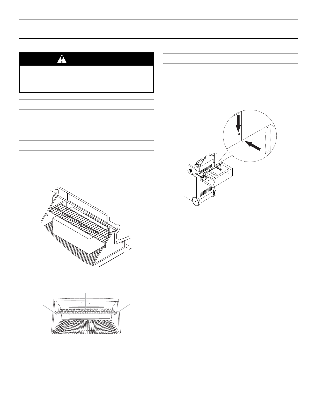
Unpack Gril l
1. Remove all packaging materials and remove grill from the
shipping base.
2. Move grill close to desired outdoor location.
3. Open the grill hood.
Remove Packaging Materi al Inside the Grill
1. Use a utility knife to cut yellow straps and packing tape to
open box from top and remove the boxes.
2. Remove the warmi ng shelf an d grill grate s from inside the grill
and remove the package inside the firebox.
3. Remove foam block and wrap from inside the grill.
Attach Right Side Shelf with Sear Burner
1. Unpack right side shelf with sear burner.
2. Remove 3 screws from the side of the searing side burner.
3. Loosen the 2 screws on the grill side panel and align the
bottom keyhole slots on the side shelf with the loosened
screws. Hook the side s helf onto th e two l oosened screws a nd
let the side shelf slide down so the screws are in the narrow
neck of the slots.
4. Replace the grill grates.
5. Place warming shelf on brackets as shown.
A. Warming shelf brackets
B. Warming shelf
IMPORTANT: This step is meant to help with the installation,
but do not depen d s ol ely o n t he tw o sc rews to hold the weight
of the sear burner.
4. Attach the top of the side shelf to the grill (A) by inserting the
3 screws removed in Step 2 into the side shel f from inside the
grill hood and tighten.
5. Attach the botto m of the si de she lf to t he si de p an el (B) of the
grill by tightening the 2 screws inserted in the keyhole slots in
Step3.
9
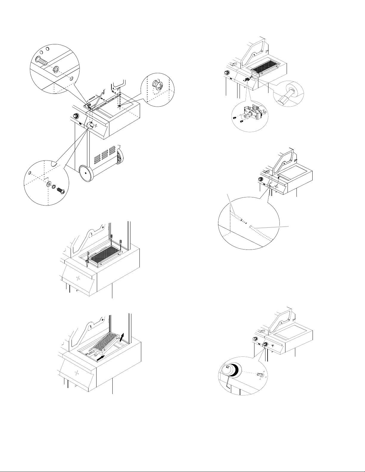
6. Attach the side shelf to the control panel (C) by tightening the
A
B
C
A
B
A
B
screw from the side shelf control panel to the main control
panel.
12. Replace the searing side burner, angling it so that the side
burner tube slides over the valve orifice (B).
13. Connect electrical plugs on underside of sear burner.
7. Remove the 3 screws from the sea ring side burner.
8. Remove the searing side burrne r.
A. Electrical plug from grill
B. Electrical plug from sear burner
14. To install the searing side burner knob, locate the opening on
the underside of the knob behind the rubber grip. Slowly peel
back the rubber grip.
15. Insert an Allen wrench into the hole and into the setscrew.
Insert the valve stem into the knob and tighten the setscrew.
9. Remove the 2 screws from the side burner valve assembly
(A).
10. Push the valve stem out through th e openin g in the front of the
side burner shelf, lining up the holes in the side burner valve
assembly wi th the openings on the side burner shelf.
16. The igniter battery is not factory installed. A “AA” si ze a lk ali ne
battery is located in the acce ssory bo x on the g rill gra te. Inst all
battery at this time following the inst ruc tio ns in “Replacing the
Igniter Battery” section.
11. Attach the side burner valve assembly to the side burner shelf
with the screws removed in Step 9 (A).
10
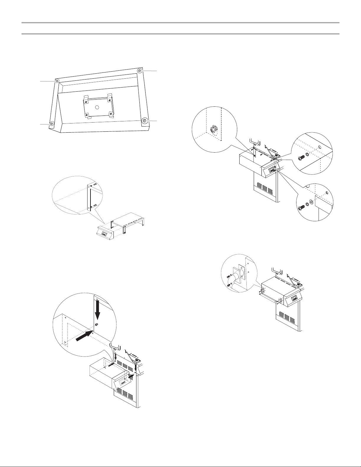
Attach Left Side Shelf
A
A
A
A
B
A
C
1. Unpack left side shelf and timer control panel. Remove two
“AA” batteries and set aside.
2. Remove the 4 screws from the outside edge of the timer
control panel.
A. Remove these screws.
3. Align the 4 holes of the timer control panel with the 4 holes in
the side shelf. Attach the timer control panel to the side shelf
from inside the side shelf using the 4 screws removed in
Step2. Tighten the screws.
6. Remove 3 screws from the side of the side shelf.
7. Attach the top of the side shelf to the grill (B) by inserting the
3 screws removed in Step 6 into the side shel f from inside the
grill hood and tighten.
8. Attach the botto m of the si de she lf to t he si de p an el (A) of the
grill by tightening the 2 screws inserted in the keyhole slots in
Step5.
9. Attach the side shelf to the control panel (C) by tightening the
screw from the side shelf control panel to the main control
panel.
10. Attach side shelf push bar by aligning the screw holes on the
side shelf with the screw holes in the push bar. Insert the
screws into the push bar screw holes and then into the side
4. Install two “AA” size alkaline batteries into the back of the
timer control panel.
5. Loosen the 2 screws on the grill side panel and align the
bottom keyhole slot s on the side she lf with the loo se ned
screws. Hook the side shelf onto the two loo sened screws and
let the side shelf slide down so the screws are in the narrow
neck of the slots.
shelf and tighten.
IMPORTANT: This step is meant to help with the installation,
but do not depen d s ol ely o n the tw o sc rews to hold the weight
of the sear burner.
11
 Loading...