

Jenn-Air 27inch wall oven, 30inch wall oven, WM27160, WM27260, WM27460 Installation Instructions Manual
...
T
Built-In 27"& 30" t
Electric Combination Wall Ovens 303.6..oE omiJENN'AIR,.o,... L,s,.4. 50.01
INSTALLATION
INSTRUCTIONS
PART NO.210410
Model numbers covered by these instructions: WM27160, WM27260, WM27460, WM30460
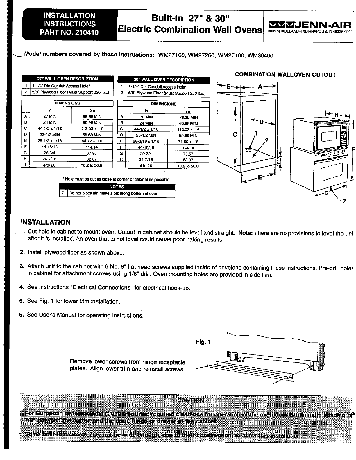
COMBINATIONWALLOVEN CUTOUT
1-1/4" Dia Conduit Access Hole* 1-1/4" Dia Conduit Access Hole* _--B-_---- A----_I
5/5" Plywood Floor (Must Support 250 Ibs.) 5/8" Plywood Floor (Must Support 250 Ibs.)
- -
A 27 MIN 68.58 MIN A 30 MIN 76.20 MIN ..------------- I
B 24 MIN 60.96 MIN B 24 MIN 60.96 MIN
C 44-1/2±1/16 113.03±.16 C 44-1/2±1/16 113.03 ±.16
D 23-1/2 MIN 59.69 MIN D 23-1/2 MIN 59,69 MIN C 1
E 25-1/2±1/16 64.77:L .16 E 28-3/16±1116 71.60±.16
F 44-15116 114.14 F 44-15116 114.14 1 r
G 26-3/4 67.95 G 29-5/4 75.57 •
H 24-7/16 62.07 H 24-7/16 62.07
I 4 to 20 t 0.2 to 50.8 I 4 to 20 10.2 to 50.8 __
• Hole must be cut as close to comer of cabinet as possible. _'_E
I Do not block air intake slots along bottom of oven
INSTALLATION
• Cut hole in cabinet to mount oven. Cutout incabinetshouldbe levelandstraight.Note:Thereare noprovisionsto leveltheuni
afteritis installed.Anoven that isnotlevel couldcause poorbakingresults,
2. Installplywoodflooras shownabove.
3. Attachunittothecabinetwith6No. 8"flatheadscrewssuppliedinsideofenvelopecontainingtheseinstructions.Pre-ddllhole.=
incabinetforattachmentscrewsusing1/8"drill.Oven mountingholesareprovidedinsidetrim.
4. See instructions"ElectricalConnections"forelectricalhook-up.
5. See Fig. 1 forlowertriminstallation.
6. See User'sManualfor operatinginstructions.
Fig. 1 _
Removelowerscrewsfromhingereceptacle
plates. Alignlowertrim andreinstallscrews iv
Microwave Oven _JENN-AIR
|
3035 SHADELAND INDIANAPOUS. IN 46226-0g01J
INSTALLATION
INSTRUCTIONS
PART NO. 210649
Built-In Kit
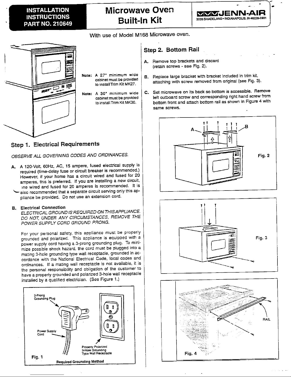
With use of Model M168 Microwave oven.
___ Step 2. Bottom Rail
A. Remove top brackets and d_scard
(retain screws - see Fig. 2).
Note: A 27" minimum wide
cadinetmusthe provided B. Replace large bracket with bracket included in trim kit,
toinstallTrim Kit MK27. att,9.chingwith screw removed from original (see Fig. 3).
Note: A 30" minimum wide C. Set microwave on its back so bottom is accessible. Remove
Cabinetmust beprovided left outboard screw and corresponding right hand screw from
toinstallTrim KitMK30. bottom front and attach bottom rail as shown in Figure 4 with
ssme screws.
Step 1. Electrical Requirements _------_'__L=._
OBSERVE ALL GOVERNING CODES AND ORDINANCES, _ Fig. 2
A. A 120-Volt, 60Hz, AC, 15 ampere, fused electrical supply is
required (time-delay fuse or circuit breaker is recommended.)
However, if your home has a circuit wired and fused for 20
amperes, this is preferred. If you are installing s new circuit,
_ne wired and fused for 20 amperes is recommended. It is
also recommended that s separate circuit serving only this ap-
pliance be provided. Do not use an extension cord.
B. Electrical Connection
ELECTRICAL GROUND IS REQUIRED ON THISAPPLIANCE.
DO NOT, UNDER ANY CIRCUMSTANCES, REMOVE THE
POWER SUPPLY CORD GROUND PRONG. 4p
For your personal safety, this apptisnce must be properly
grounded and polarized. This appliance is equipped with a _ _f
power supply cord having • 3-prong grounding plug. To mini- C'-""-'J !._!/ Fig. 3
mJze possible shock hazard, the cord must be plugged into s I _..J }_!1
mating 3-hole greunding type wall receptacle, grounded in ac-
cordance with the National E!ecthcal Code, local codes and
ordinances. If a mating wall receptscJe is not svsiisbie, it is _-_
the personal responsibility and obligation of the customer to
have a properly grounded and poJsrized 3-hoJe waIJreceptscie
installed by a qualified electrician, (See Figure 1.)
3-Prong
Grounding Plug
•
(_ - " ; RAIL
Power Suppty
Cora _ ,
ProPerty Potarized .;;_,; : _.
3-Ha_eGrounding .:::_
Fig. 1 "ry_eWaJlReceotade Fig. 4
RequiredGroundingMethod
 Loading...