

Jenn-Air 204347 Installation Instructions Manual
INSTALLATION
INSTRUCTIONS
PARTNo. 204347
BUILT-INELECTRICWALLOVENS _[] eLIoENMN-AlpA NRy
FOR 27" WALL CABINET 303sSHADELAN£)" INDIANAPOLISIN46226-0901
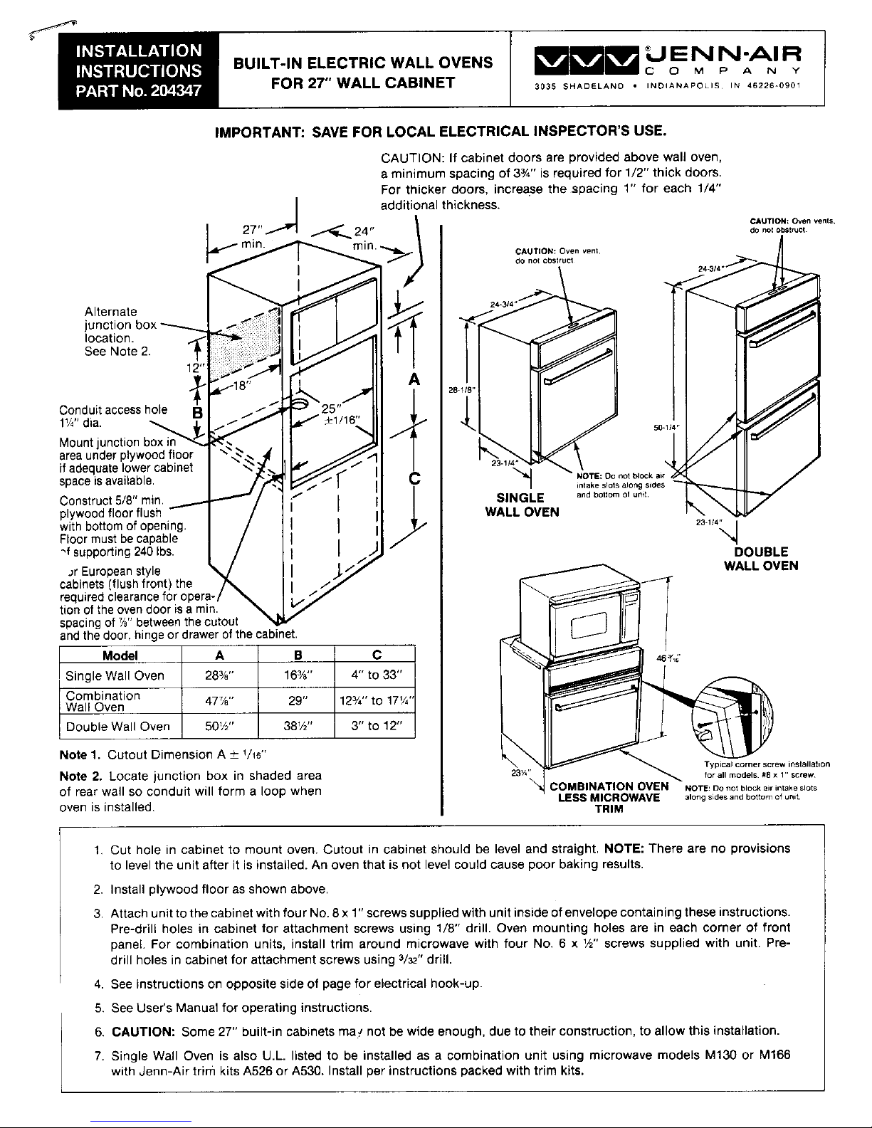
IMPORTANT: SAVE FOR LOCAL ELECTRICAL INSPECTOR'S USE.
CAUTION: If cabinet doors are provided above wall oven,
a minimum spacing of 33/4'' is required for 1/2" thick doors.
For thicker doors, increase the spacing 1" for each 1/4"
J additional thickness.
,._._ CAUTION: Oven venIs.
27" _--_r-_. P4".r_in CAUTION: Oven vent, /1de no{ obstruct
do no_obstruct _'_ _J
Alternate _ _ -"--,.f.,_- _-_
location.
See Note 2. ] ]I _J"_
A
28-118" J
Conduit access hole /
ount,lv'a ,
area under plywood floor
if adequate lower cabinet .23.,_-,,_-_ !OT_:_o_ / 7,/
space is available. C _to_C_
Construct 5/8" min. SINGLE andbotlemofunit
plywoodfloor flush WALL OVEN %
with bottom of opening. 23-114_.I
Floor must be capable '4
_f supporting 240 Ibs. DOUBLE
Jr Europeanstyle __ _ WALL OVEN
cabinets (flush front) the
required clearance for c
tion of the oven door is a min.
spacing of T/8"between the cutout
and the door, hinge or drawer of the cabinet.
Model A B C 4e_'4'
S ng eWa Oven 28%" 16%" 4" to 33" _
Combination 29"
Wall Oven 477/a" 123/4"to 17W
Double Wall Oven J 50W' 38W' 3" to 12" _
Note 1. Cutout Dimension A 4- _/_6"'
Typical corner screw installation
for all models #8 x 1"screw
Note 2. Locate junction box in shaded area 23/,"
of rear wall so conduit will form a loop when :OMBINATION OVEN NOTE:Donorblockairintakeslots
LESSMICROWAVE along sides and bottom of unit
oven is installed. TRIM
1. Cut hole in cabinet to mount oven. Cutout in cabinet should be level and straight. NOTE: There are no provisions
to level the unit after it is installed. An oven that is not level could cause poor baking results.
2. Install plywood floor as shown above.
3. Attach unit to the cabinet with four No. 8 x 1" screws supplied with unit inside of envelope containing these instructions.
Pre-drill holes in cabinet for attachment screws using 1/8" drill. Oven mounting holes are in each corner of front
panel. For combination units, install trim around microwave with four No. 6 x W' screws supplied with unit. Pre-
drill holes in cabinet for attachment screws using 3/32"drill.
4. See instructions on opposite side of page for electrical hook-up.
5. See User's Manual for operating instructions.
6. CAUTION: Some 27" built-in cabinets may not be wide enough, due to their construction, to allow this installation.
7. Single Wall Oven is also U.L. listed to be installed as a combination unit using microwave models M130 or M166
with Jenn-Air trim kits A526 or A530. Install per instructions packed with trim kits.
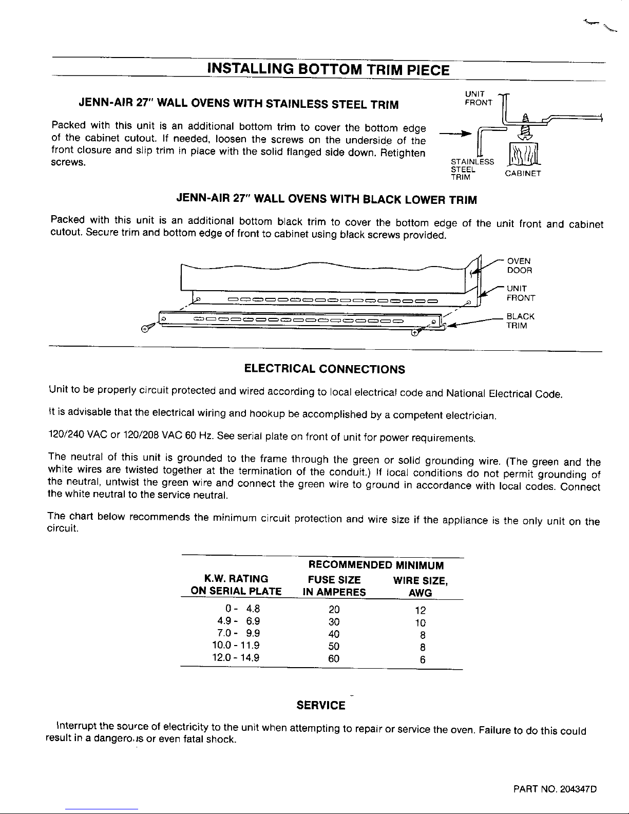
INSTALLING BOTTOM TRIM PIECE
UNIT _
JENN-AIR 27" WALL OVENS WITH STAINLESS STEEL TRIM FRONT
Packed with this unit is an additional bottom trim to cover the bottom edge _ fl " '
of the cabinet cutout. }f needed, loosen the screws on the underside of the L[
front closure and slip trim in place with the solid flanged side down. Retighten
STAINLESS
screws. STEEL CABINET
TR_M
JENN-AIR 27" WALL OVENS WITH BLACK LOWER TRIM
Packed with this unit is an additional bottom black trim to cover the bottom edge of the unit front and cabinet
cutout. Secure trim and bottom edge of front to cabinet using black screws provided.
_ OVEN
J._ _ _, _"_ FRONT
(_"{ f /" c=:=__ _ = _ _ _ c=__ c::=3c=:3_:_ ,_ _ c::_ ¢::=3 ,'_ L_ ''_- TR'MBLACK
ELECTRICAL CONNECTIONS
Unit to be properly circuit protected and wired according to local electrical code and National Electrical Code.
It is advisable that the electrical wiring and hookup be accomplished by a competent electrician.
120/240 VAC or 120/208 VAC 60 Hz. See serial plate on front of unit for power requirements.
The neutral of this unit is grounded to the frame through the green or solid grounding wire. (The green and the
white wires are twisted together at the termination of the conduit.) If local conditions do not permit grounding of
the neutral, untwist the green wire and connect the green wire to ground in accordance with local codes. Connect
the white neutral to the service neutral.
The chart below recommends the minimum circuit protection and wire size if the appliance is the only unit on the
circuit.
RECOMMENDED MINIMUM
K,W. RATING FUSE SIZE WIRE SIZE,
ON SERIAL PLATE IN AMPERES AWG
0- 4.8 20 12
4.9- 6.9 30 10
7.0- 9.9 40 8
10.0 - 11.9 50 8
12.0 - 14.9 60 6
SERVICE
Interrupt the source of electricity to the unit when attempting to repair or service the oven. Failure to do this could
result in a dangero4s or even fatal shock.
PART NO.204347D
 Loading...