

Page 1

SPECIALIST RF DESIGNS
© Copyright Wood & Douglas 2002
Version: 1.3
Issue: July 2002
HERMES RADIO MODEM
OPERATING INSTRUCTIONS
(1892 1300)
LATTICE HOUSE
BAUGHURST
BASINGSTOKE
UK RG26 5LP
Tel: +44 (0) 118 981 1444 Fax: +44 (0) 118 981 1567
Page 2

Table Of Contents
1 INTRODUCTION ..............................................4
2 CONNECTIONS & INDICATIONS .................................5
2.1 RS232 Connector .......................................5
2.2 Power Connector ........................................6
2.3 RF Connector ...........................................6
2.4 Front Panel Indications ...................................6
3 MODEM OPERATION ..........................................7
3.1 Introduction ............................................7
3.2 Handshaking Operation During Transmit and Receive .........7
3.3 Data Transfer Modes .....................................8
3.4 RS232 Data Handling ....................................8
3.5 Receive-to-Transmit Turnround ............................8
4 LIST OF COMMANDS: ........................................10
4.1 Command Mode ........................................10
4.1.1 Activation of the Command Mode: .....................10
4.1.2 Ending of Command Mode ..........................11
4.2 Command Syntax ......................................11
4.3 Baud Rate (AT B0) ......................................12
4.4 Parity (ATB1) ..........................................12
4.5 Format Mode (AT F) .....................................13
4.6 Engineering Test Modes (AT In) ...........................14
4.7 Software Version Information (AT I9) .......................15
4.8 Command Mode Guard Time (AT S154) .....................15
4.9 Centre Radio Frequency (AT S155) ........................15
4.10 Received Signal Strength Indication (RSSI) (AT S156) ........16
4.11 Radio Channel (AT S157) ................................17
4.12 Data Quality (AT S158) ..................................17
4.13 Squelch (AT S159) ......................................18
4.14 Transmission Power (AT S160) ...........................19
4.15 Channel Step Size (AT S161) .............................20
4.16 Test Message Period (AT S162) ...........................20
4.17 Over-Air Symbol Rate (AT S163) ..........................21
4.18 Preamble Period (AT S165) ...............................21
4.19 Frame Synch Tolerance (AT S166) .........................22
4.20 Invert Symbol (AT S167) .................................22
4.21 Squelch Delay (AT S168) .................................23
4.22 Enable/Disable Receive Output Data (AT &D) ...............23
4.23 Enable/Disable Input Echo Data (AT &E) ...................23
4.24 Radio Frequency (AT &F) ................................24
4.25 Save parameters (AT &W) ................................24
4.26 Restore defaults (AT &Y8) ...............................24
4.27 Display parameters (ATT?) ...............................25
4.28 Code Loader (AT S2000) .................................26
Page 3

5 HARDWARE SPECIFICATION ..................................28
5.1 Introduction ...........................................28
5.2 RS232 Port Parameters ..................................28
5.3 Radio Specifications ....................................29
6 MECHANICAL SPECIFICATION ................................30
6.1.1 Casting Enclosure .................................30
6.1.2 3U Rack Mounting Enclosure .........................30
6.2 Operating conditions ....................................32
6.3 Vibration Specifications: .................................32
6.4 Type Approvals ........................................32
LIST OF FIGURES
Figure 1 Timing Information ..........................................9
Figure 2 Front View of Casting ......................................31
Figure 3 Rear View of Casting .......................................31
Figure 4 3U Enclosure .............................................31
LIST OF TABLES
Table 1 Data Connections ...........................................5
Table 2 Power Connections ..........................................6
Table 3 Timing Data ................................................9
Table 4 RSSI Levels ...............................................16
Table 6 Squelch Levels ............................................18
Table 7 Power Levels for G-MAX Radios ...............................19
Table 8 Power Levels for SXn50 Radios ...............................19
Hermes Operator Note Page 3 of 32
Page 4

1 INTRODUCTION
This document describes the operation of the Wood and Douglas Hermes
Radio Modem.
The Hermes modems provide a transparent data link for a wide range of
applications. The internal modem can be used with a range of Wood &
Douglas RF products to give great choice in the operating frequency and
transmit power. Two enclosure types are available to suit different
applications.
The Hermes uses 4-Level Frequency Shift Keying (FSK) technology to
achieve a RF link data rate of 19,200 baud in a 25kHz channel spacing and
9,600 baud in a 12.5kHz channel spacing.
One of the radio transceivers (the G-Max family) used inside the Hermes is
designed for harsh environments and operates over a wide temperature
range and a high vibration environment.
The standard Hermes is fitted with the SXn50 range of transceivers. This
family has products at VHF, UHF and 868MHz, with a maximum transmit
power of 500mW.
Hermes Operator Note Page 4 of 32
Page 5

2 CONNECTIONS & INDICATIONS
2.1 RS232 Connector
The RS232 connections are made via a 9 way D female with the following
connections:
Pin No. Function
1 CD Output
Set (+ve) when a RF signal above a certain level is present at the
RF connector. The threshold is programmable over 10 levels that
are defined in section 5.13
2 RXD RS232 data level data output
3 TXD RS232 level data input
4 DTR RS232 level input
When set (+ve) by the DTE (host processor) the modem and
transceiver is turned on. The max/min levels are:
DTR Vin Min. (off state) = -15V
DTR Vin Max. (off state) = +2.5V
DTR Vin Min (on state) = +5V
DTR Vin Max (on state) = +15V
DTR Iin Max(on state) = 4mA
5 Signal Ground
6 DSR RS232 level output
Set (+ve) after power is applied to the modem or when the DTE
(host processor) sets DTR +ve. The output is active when the
modem is ready to receive data. The time taken for the output to
become active is <50ms from when DSR or power is applied to
the modem.
7 RTS RS232 level input
The RTS input must be set (+ve) for both data and configuration.
Data is ignored when RTS is clear (-ve).
8 CTS RS232 level output
Set (+ve) if the transmit RS232 data into the modem can be
accepted and the RTS input is set, it is cleared (-ve) otherwise.
Clearing of this signal indicates that the input transmit buffer is
nearly full .The RS232 data must be stopped within 10 bytes of
this signal being cleared. After this point the data is ignored. The
CTS signal is set again if there is room for more than 10 bytes.
9 n/c
Table 1 Data Connections
Hermes Operator Note Page 5 of 32
Page 6

2.2 Power Connector
The power and ancillary connections are made via a 9 way D male
connector. The power supply input is fully isolated from the chassis of the
module.
Note: The power supply cannot be used as an RS232 input line.
Pin No. Function
1 RSSI Received Signal Strength Output
Analogue output proportional to the level of the RF input
Level at -110dBm input = ~0.6V and at -60dBm = ~2.1V
2 n/c
3, 4 +ve Supply Input (9 - 36VDC)
Receive current <100mA at 24VDC input
Transmit current <400mA at 1000mW RF output, 24VDC input
(reverse voltage protection with re-settable "polyfuse")
5 Power Supply Ground (isolated from enclosure)
6 I2C Bus Clock (engineering use only)
7 0V (chassis of enclosure)
8 I2C Bus Data (engineering use only)
9 Power Supply Ground (isolated from enclosure)
Table 2 Power Connections
2.3 RF Connector
The RF connection to the modem is a female TNC bulkhead connector.
2.4 Front Panel Indications
There are 3 LED indicators which show the operation of the unit as follows:
P Green Power On when DC supply input present and DTR input
S Orange Status Flashes orange when the transceiver is switched
is high (> 3V)
to transmit or receive. Continuous orange if the
transceiver goes “Out Of Lock” (OOL) which
happens on failure, or when an invalid frequency
is programmed into it.
T Red TX On when the transmitter is turned on.
These LEDs are next to the connectors on both types of enclosure.
Hermes Operator Note Page 6 of 32
Page 7

3 MODEM OPERATION
3.1 Introduction
The internal modem power supply system is turned on/off with the DTR
input. The modem is ready after an initialisation period. The modem enters
receive mode using the last set of configuration parameters (RF channel,
squelch level etc).
The modem starts the transmit sequence after the first data byte is received
from the RS232 port. The incoming data is stored while the transmitter is
turned on and the preamble output. The start, stop and parity (if 8 bit data)
are stripped off the input data stream and the data stored as 8 bits only.
The transmission is ended when the input buffer is empty. After the
transmission is complete and the transmitter turned off, the modem
switches back to receive mode. Transmission has priority over reception so
the user has to check by means of the CD handshake line if the radio
channel is free before inputting data.
The timing of the power, handshaking and data transfer is shown in Figure 1
for the G-MAX radio (running at 9600 baud over-air in a 12.5kHz channel)
and for the SXn50 series of radios (running at 19,200 baud over-air in a
25kHz channel).
3.2 Handshaking Operation During Transmit and Receive
The DTE must set the RTS input for the modem to accept data. The RTS
input can be set continuously if no hardware handshake lines are available
on the DTE. The CTS line must be monitored for data packets greater than
256 bytes to ensure that input buffer overflow does not occur. If the data
input is not stopped within 10 characters from the point of buffer overflow,
the input data will be discarded.
Handshaking is also required during the code loading.
The modem starts transmitting when the data is input, regardless of the
state of the CD output. The DTE must check the CD output prior to data
transmission. When the CD output is set this indicates that a RF signal is
present at the antenna. This output is only active when the modem is not
transmitting.
Hermes Operator Note Page 7 of 32
Page 8

3.3 Data Transfer Modes
In FEC mode every byte of the data, including the "end-of-file" string is
scrambled within the modem to ensure that the error correction mechanism
operates over non-consecutive bits in the data stream. The frame sync
pattern is not scrambled.
In non-FEC (High Speed) mode the data is scrambled to minimise problems
that could occur with many consecutive 1's or 0's in the input data stream.
3.4 RS232 Data Handling
The over-air data rate is faster than the input data rate because only the 8
data bits of the input character of 11 bits are transmitted. To ensure that no
data is lost at the output, and for the modem to transmit the data in one
continuous packet it is essential that the input and output data rates are set
to at least 2 x the over-air-baud rate. The default over-air baud rate for this
modem working in a 12.5kHz channel is 9600 baud. For this set the input
and output RS232 data rates to 19,200. For a 25kHz channel, with an overair baud rate of 19,200, set the data rates to 38,400 baud.
Some applications running under the Windows™ operating system output
the data with gaps between single or groups of characters. In some cases
this can reduce the character rate below the over-air data rate. When this
occurs, the system will assume that the input data has finished and will turn
the transmitter off when the input data buffer is empty.
If more characters are input to the modem while the transmitter is being
turned off, the transmit process will re-start. This will appear as bursts of
RF close together. At the receive end, the timing of the data will change as
there will be gaps in the received data stream.
This mode of operation ensures that small data packets are transmitted in
as short a time as possible to reduce the on-air time to a minimum.
3.5 Receive-to-Transmit Turnround
After the last character of a packet of data is output from the receiver, the
receive system is still processing the “end-of-packet” data. This takes ~5ms
when in non-FEC mode and ~10ms in FEC mode. During this period the
processor does not accept any input data. The figures apply for default
settings: 19,200 baud rate and 4800 symbol/sec over-air baud rate
Hermes Operator Note Page 8 of 32
Page 9
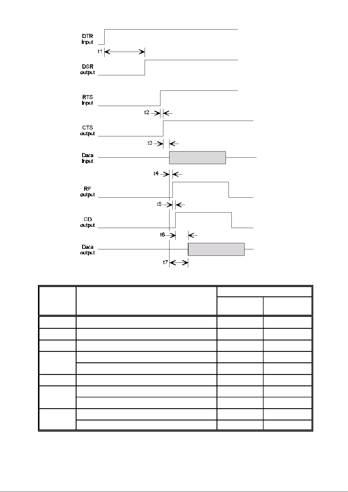
Figure 1 Timing Information
Time (ms)
Function Description
G-MAX
(9600 baud)
t1 DTR input-to-modem DSR output <90 <90
t2 RTS input to CTS output <0.5 <0.5
t3 CTS output to Data input >0.1 >0.1
t4 Data input to RF output (non-FEC mode) <25 <25
Data input to RF output (FEC mode) <25 <25
t5 RF output to CD output (at RX end) <5 <2.5
t6 CD output to data output (non-FEC mode) <30 <30
CD output to data output (FEC mode) <50 <45
t7 Data input to Data output (non-FEC mode) <50 <45
Data input to Data output (FEC mode) <75 <55
Table 3 Timing Data
SXn50
(19200 baud)
Hermes Operator Note Page 9 of 32
Page 10

4 LIST OF COMMANDS:
4.1 Command Mode
The modem is configurable through the RS232 port. The Command Mode
has to be activated to do this, as detailed in the following paragraphs:
4.1.1 Activation of the Command Mode:
The Command Mode is activated with the string:
<wait>+++<wait> <CR><LF>
Where <wait> is a programmable period after transmitting data (which is set
by register S154) which has a nominal value of 10ms.
The modem responds with:
OK<CR><LF>
The modem is now ready to be configured. Transmitting or reception is
blocked during Command Mode.
If the "+++" string is input without a <CR><LF> then the string is transmitted
as normal data. Note that one or more consecutive “+” characters in the
input data are held in the modem until it is determined that it is not a “+++”
string.
The configuration mode is only accepted if the RTS line is set. The “+++”
string is only accepted if this string is the first three characters and there has
been no data for greater than the time set by register S154.
The +++ string is only transmitted over the air if embedded in a data string as
described above.
Important: any configuration changes made are only saved to the
non-volatile memory after a write command (AT &W).
Note that the communication parameters (baudrate etc) are the programmed
parameters.
Hermes Operator Note Page 10 of 32
Page 11

4.1.2 Ending of Command Mode
The command mode is ended by inputting the string:
ATO<CR><LF>
The modem responds with:
OK<CR><LF>
The modem is now ready for normal modem operation.
Note that the communication parameters (baudrate etc) are the programmed
parameters.
4.2 Command Syntax
4.2.1 Note: Capital letters MUST be used for all command instructions.
4.2.2 All syntax commands with multiple ‘n’ ‘s accept multiple formats. For
example, if ‘nnn’ is specified in the command string, then the following will
be valid:
1 or +1
01 or +01
001 or +001
4.2.3 The commands for reading registers have the form:
AT S158?<CR><LF>
The answer to this query is:
nnn<CR><LF>
4.2.4 After setting a parameter the modem responds with:
OK<CR><LF> if a valid entry and
ERROR<CR><LF> if an invalid entry
Hermes Operator Note Page 11 of 32
Page 12

4.3 Baud Rate (AT B0)
When the baud rate is changed, the change is made after the Command
Mode is ended (with the AT O command).
The baud rate is set with the following command:
Baud Rate AT B0=n <CR><LF>
Where: n = 1 4800
Default: n = 3 for 12.5kHz radios
Read: AT B0?<CR><LF>
Note: this shows the new value, even though the change is
Read Return: n<CR><LF>
Example: AT B0=2<CR><LF> for 9600 baud
n = 2 9600
n = 3 19200
n = 4 38400
n = 4 for 25kHz radios
not implemented until the Command Mode is exited.
4.4 Parity (ATB1)
The number of data bits is fixed to 8. Parity at the RS232 input to the
transmitter has no effect and is not transmitted. The 8 data bits can be used
to transmit 7 data bits + 1 parity bit. In this case the modem has to be set to
no parity.
The number of stop bits at the RS232 input to the transmitter can be 1 or
more. The number of stop bits at the receiver RS232 output is fixed at 1. This
is to avoid congestion of the output data.
When the parity is changed, the change is made after Command Mode is
ended (with the AT O command).
The parity is set with the following command:
Parity AT B1=n<CR><LF>
Where: n = 1 even
Default: 3
Read: AT B1?<CR><LF>
Read Return: n<CR><LF>
Example: AT B1=n<CR><LF>
n = 2 odd
n = 3 none
Note: this shows the new value, even though the change is
not implemented until the Command Mode is exited.
Hermes Operator Note Page 12 of 32
Page 13

4.5 Format Mode (AT F)
This command turns the Forward Error Correction (FEC) mode on and off.
The over-air format allows for higher speed operation, but with reduced Bit
Error Rate (BER) performance with the FEC turned off, or lower speed,
improved BER with the FEC turned on.
Figure 1 and the associated table give the timing information for both modes
of operation.
The command is:
Format mode AT F=n<CR><LF>
Where n=0 mode with FEC
Default: n=1 (non-FEC mode)
Read: AT F?<CR><LF>
Read Return: n<CR><LF>
Example: AT F=1<CR><LF>
n=1 high speed mode without FEC
Hermes Operator Note Page 13 of 32
Page 14

4.6 Engineering Test Modes (AT In)
Format modes:
To enable the function AT In=1 <CR><LF>
To disable the function AT In=0 <CR><LF>
Modem responds with OK <CR><LF>
Read status: AT In?<CR><LF>
Modem responds with m <CR><LF> where m=0, not active
Where n = 2 Output Continuous Preamble (used for
checking transmitter and receiver). The
preamble is transmitted until stopped by the
ATI2=0 or AT I=10 commands, or ending the
command mode. Note: for a G-Max, this test
must not be run for >10 minutes as damage to
the transceiver may occur.
n = 3 Output a series of 49 byte long data packets
with a programmed period between each
packet set with register S162. The message
data sent is: “The quick brown fox jumps over
the lazy dog.<CR><LF>” Each line of data is
pre-ceded by “XX “ where XX is a line number
which increments from 00 - 99.
m=1, active
The data is transmitted until stopped by the
ATI3=0 or AT I=10 commands, or ending
command mode.
n = 4 Adds the Output Data quality and Signal level
data to the end of each received data packet.
This is ended by the ATI4=0 or AT I=10
command. The data format is:
R:XX, D:XXX<CR><LF>
where XX = 1 - 10 and XXX = 66 - 256 as
defined in paragraphs 5.10 and 5.12
Note: if data is received before the values have
been read then R:XX, D:XXX<CR><LF> will be
output.
n = 9 Gives information about the software version
(refer to paragraph 5.7).
n = 10 Turn off test modes
Hermes Operator Note Page 14 of 32
Page 15

4.7 Software Version Information (AT I9)
This command tells the modem to output information about the software
version.
Example: ATI9=1<CR><LF> return software version
or ATI9<CR><LF>
Return: ‘an ASCII string detailing the ID and versions of the
internal processors’ <CR><LF>
An example of the return data is as follows:
Files:
Main micro:"QL3z10", Ver.:1.01.05, Date:31/10/2001
Slave micro:"Slave",Ver.:0.00.02, Date:12/11/20001
Flash Programmer:"karfl3", Ver.:1.00.03, Date:24/10/2001
Hermes®, © 2001, Wood & Douglas Ltd.
4.8 Command Mode Guard Time (AT S154)
To enable the transmission of the command sequence within a packet of
data, a guard time is placed around the command sequence. If the gap
between the characters in the command mode string is less than this guard
time, then the data string is assumed to be part of the data. This includes
the gap between the last received data byte and the first “+”. The command
is:
AT S154=nnn<CR><LF>
Where nnn =0 to 255 ms
Default: 10
Read: AT S154?<CR><LF> read the setting
Read Return: nnn<CR><LF>
Example: AT S154=10<CR><LF> set 10 msec time delay
4.9 Centre Radio Frequency (AT S155)
The channel change system for the Hermes is based around a centre
frequency. The Hermes is programmed with a factory set centre frequency
that is the centre of the RF switching band. The channel change is carried
out by programming a channel step size (typically 12.5kHz) and setting 00-99
above or 00-99 channels below the centre frequency. The centre frequency
can be changed and stored in EEPROM for moving the programmed
channels. A temporary change can also be made by storing a new centre
frequency in RAM. This is not restored if power is lost to the unit.
Hermes Operator Note Page 15 of 32
Page 16

The centre radio frequency of the modem is set as follows:
AT S155=nnn.nnnnnn<CR><LF>
Where: nnn.nnnnnn is the format of the input string for the
frequency in MHz
Default: current centre frequency.
Read: AT S155?<CR><LF>
Read Return: nnn.nnnnnn<CR><LF>
Example: AT S155=458.5<CR><LF> sets 458.5MHz
AT S155=458.500000<CR><LF> sets 458.5MHz
Note that frequencies in multiples of either 12.5kHz or 10kHz only are
acceptable. If a whole number of MHz is entered a “.” must be entered
before the <CR><LF>.
If the wrong centre frequency is entered the modem will respond with the
following error message and the entry will be ignored:
ERROR<CR><LF>
4.10 Received Signal Strength Indication (RSSI) (AT S156)
This request to the modem gives a response of nn <CR><LF>, where the nn
is the value of the Received Signal Strength of the radio carrier present at the
antenna at that time. The returned value of RSSI is in the range of 1 to 10.
The level of RF level of each value is given in the following table:
RSSI Level Level at RF Input ( dBm ±2dB)
01 -114 to -120
02 -108 to -114
03 -102 to -108
04 -96 to -102
05 -90 to -96
06 -84 to -90
07 -78 to -84
08 -72 to -78
09 -66 to -72
10 > -66
XX Not available
Table 4 RSSI Levels
Hermes Operator Note Page 16 of 32
Page 17

The RSSI level is requested with the command:
AT S156?<CR><LF>
Read Return: nn<CR><LF>
The data can be added to the end of each received packet as defined in
paragraph 5.6.
4.11 Radio Channel (AT S157)
The radio transceiver is programmed with a centre frequency (using the AT
S155 command). This frequency is set up in the factory at the centre of the
RF switching bandwidth. Once programmed with this frequency a Channel
Step Size (using AT S161 command) can be programmed. ±99 channels
can then be set with this command to give a total of 199 frequencies.
The command for setting the radio channel is
AT S157=n<CR><LF>
Where: n = ±0 to ±99
Default: 0 (which is printed on screen as +00)
Read AT S157?<CR><LF>
Read Return: ±nn<CR><LF>
Example: AT S157=-10<CR><LF> sets the channel to -10
4.12 Data Quality (AT S158)
This request for data gives an indication of the quality of the data reception.
The signal quality is read from the modem system at the end of each
received packet and stored to give a consistent result when the quality is
requested. The value is in the range 64 to 255, the larger the value, the
higher the quality. The command for requesting the data quality is
Read Return: nnn<CR><LF>
If no data has been received, XXX is returned.
The data can be added to the end of each received packet as defined in
paragraph 5.6.
AT S158?<CR><LF>
Hermes Operator Note Page 17 of 32
Page 18

4.13 Squelch (AT S159)
This command sets the squelch threshold to one of 10 pre-set levels as
shown in the Table 6.
This command enables the user to reduce the chances of local interference
showing the channel to be busy which could reduce the occupancy of the
system.
Squelch Level Level at RF Input
( dBm ±2dB)
1 < -112
2 -110 to -112
3 -108 to -110
4 -105 to -108
5 -103 to -105
6 -101 to -103
7 -99 to -101
8 -97 to -99
9 -95 to -97
10 > -95
Table 6 Squelch Levels
The command for setting the squelch is
AT S159=n<CR><LF>
Where: n = squelch threshold with value 1 to 10
Default: 2
Read AT S159?<CR><LF>
Read Return: nn<CR><LF>
Example: AT S159=10<CR><LF> sets the squelch to 10
Hermes Operator Note Page 18 of 32
Page 19

4.14 Transmission Power (AT S160)
The command enables the RF transmit power to be modified. Different RF
units have different capabilities and may change, depending on what is
supplied.
The SXn50 range of transceivers have 2 levels only. The levels for the 1W
and 2W versions of the G-MAX are shown in Table 7. Table 8 shows the 2
levels for the SXn50 range.
Output Power for 1W G-MAX Output Power for 2W G-MAX
Power
Level
mW
(nominal)
dBm
(nominal)
Tolerance
(dB)
mW
(nominal)
dBm
(nominal)
1 16 12 ±3 31 15 ±3
2 25 14 ±3 50 17 ±3
3 40 16 ±3 79 19 ±3
4 63 18 ±1.5 126 21 ±1.5
Tolerance
(dB)
5 100 20 ±1.5 200 23 ±1.5
6 158 22 ±1.5 316 25 ±1.5
7 251 24 ±1.5 500 27 ±1.5
8 398 26 ±1.5 794 29 ±1.5
9 631 28 ±1.5 1260 31 ±1.5
10 1000 30 ±1.5 2000 33 ±1.5
Table 7 Power Levels for G-MAX Radios
Output Power
Power
Level
mW
(nominal)
dBm
(nominal)
Tolerance
(dB)
1 5 7 ±3
2 500 27 ±1.5
Table 8 Power Levels for SXn50 Radios
Hermes Operator Note Page 19 of 32
Page 20

The power is set with the command:
AT S160=n<CR><LF>
Where: sets the power threshold <1 to 10>
Default: 10
Read AT S160?<CR><LF>
Read Return: nn<CR><LF>
Example: AT S160=-10<CR><LF> sets the power level to 10
4.15 Channel Step Size (AT S161)
This command sets the channel step size. The basic reference frequency for
the radio is either 12.5KHz or 10KHz, giving possible frequency channel
steps of 10kHz, 12.5kHz, 20kHz and 25kHz. The Channel Step Size is set
with the command:
AT S161=n<CR><LF>
Where: n=1 10 kHz
n=2 12.5 kHz
n=3 20 kHz
n=4 25 kHz
Default: n=2 (12.5 kHz)
Read: AT S161?<CR><LF>
Read Return: n<CR><LF>
Example: AT S161=1<CR><LF> sets 10 kHz channel step
If a channel step size is entered which is not a multiple of the centre
frequency an error is returned and the entry ignored. This is to ensure that
only valid frequencies on multiples of the channel step size are allowed
based on the centre frequency entered. The error message is of the form:
ERROR<CR><LF>
4.16 Test Message Period (AT S162)
This command sets the period between sending the test message. The
command is:
AT S162=n<CR><LF>
Where: n=1 - 255 in 10ms steps
Default: n=10 (100ms)
Read: AT S162?<CR><LF>
Read Return: nnn<CR><LF>
Example: AT S162=100<CR><LF> sets 1 second period
Hermes Operator Note Page 20 of 32
Page 21

4.17 Over-Air Symbol Rate (AT S163)
Note: engineering function only.
This command sets the over-air baud rate to enable the modem to be used
with different radios and channel spacings. The command format is:
AT S163=n<CR><LF>
Where: n = 2 4800 symbols/sec
n = 3 9600 symbols/sec
Default: n = 2 4800 for 12.5kHz radios
n = 3 for 25kHz radios
Read AT S163?<CR><LF>
Read Return: n<CR><LF>
Example: AT S163=3<CR><LF> sets 9600 symbols/sec
4.18 Preamble Period (AT S165)
Note: engineering function only.
This command enables the number of preamble blocks (each block equals 6
bytes) that are transmitted before each data packet to be changed. This
preamble allows for the rise time of the transmitter as well as the minimum
number of blocks required by the receiver. This allows the system
performance to be changed to enable the modem to be used with different
transceiver equipment. The command format is as follows:
AT S165=n<CR><LF>
Where: n = 1 - 10 blocks
Default: n = 2
Read AT S165?<CR><LF>
Read Return: nn<CR><LF>
Example: AT S165=10<CR><LF> sets a preamble of 11 blocks
Note that a symbol period depends on the RF baud rate (as set by paragraph
4.17).
For the G-MAX radio at 9600 symbols per second n = 2.
For the SXn50 radio at 19200 symbols per second n = 14.
Hermes Operator Note Page 21 of 32
Page 22

4.19 Frame Synch Tolerance (AT S166)
Note: engineering function only.
This command controls a receive function within the FX929 modem IC within
the modem.. The command format is as follows:
AT S166=n<CR><LF>
Where: n = 0 0 mismatches allowed in frame synch.
pattern
n = 1 2 mismatches allowed in frame synch.
pattern
n = 2 4 mismatches allowed in frame synch.
pattern
n = 3 6 mismatches allowed in frame synch.
pattern
Default: n = 0 0 mismatches allowed in frame synch.
pattern
Read AT S166?<CR><LF>
Read Return: n<CR><LF>
Example: AT S166=2<CR><LF> sets 4 mismatches allowed
4.20 Invert Symbol (AT S167)
Note: engineering function only.
This command controls the polarity of the transmit and receive audio
between the FX929 modem IC and the transceiver and allows for different
transceivers to be used with the modem. The command format is as follows:
AT S167=n<CR><LF>
Where: n = 0 RX non-inverted and TX non-inverted
n = 1 RX non-inverted and TX inverted
n = 2 RX inverted and TX non-inverted
n = 3 RX inverted and TX inverted
Default: n = 0 RX non-inverted and TX non-inverted
Read AT S167?<CR><LF>
Read Return: n<CR><LF>
Example: AT S167=1<CR><LF> RX non-inverted and TX
inverted
Hermes Operator Note Page 22 of 32
Page 23

4.21 Squelch Delay (AT S168)
Note: engineering function only.
This command changes the delay between the Squelch being received and
the FX929 modem IC looking for preamble in the receive audio. This allows
the modem to be used with different transceivers. The command format is
as follows:
AT S168=n<CR><LF>
Where: n = 1 - 255 (ms)
Default: n = 10
Read AT S168?<CR><LF>
Read Return: nnn<CR><LF>
Example: AT S168=10<CR><LF> 10ms delay between squelch
4.22 Enable/Disable Receive Output Data (AT &D)
This command disables output of any received data.
and preamble
Note that the CD output continues to operate when the data output is
disabled. The command is of the format:
AT &D=n<CR><LF>
Where: n=0 disable output
n=1 enable output
Default: n=1 (enabled)
Read: AT &D?<CR><LF>
Read Return: n<CR><LF>
Example: AT &D=1<CR><LF> enables receiver data output
4.23 Enable/Disable Input Echo Data (AT &E)
This command enables/disables input echo on the screen. The command is
of the format:
AT &E=n<CR><LF>
Where: n=0 disable echo
n=1 enable echo
Default: n=1 (enabled)
Read: AT &E?<CR><LF>
Read Return: n<CR><LF>
Example: AT &E=1<CR><LF> enables echo input
Hermes Operator Note Page 23 of 32
Page 24

4.24 Radio Frequency (AT &F)
The Hermes is programmed with a factory set centre frequency that is the
centre of the RF switching band. A new frequency can be entered directly
within the ±99 channels of the centre frequency using this command. The
channel number is re-calculated for the frequency entered using this
command.
The radio frequency of the modem is set as follows:
AT &F=nnn.nnnnnn<CR><LF>
Where: nnn.nnnnnn is the format of the input string for the
frequency in MHz
Default: none
Read: AT &F?<CR><LF>
Read Return: nnn.nnnnnn<CR><LF>
Example: AT &F=458.5<CR><LF> sets 458.5MHz
AT &F=458.500000<CR><LF> sets 458.5MHz
Note that frequencies in multiples of either 12.5kHz or 10kHz only are
acceptable. If a whole number of MHz is entered a “.” must be entered
before the <CR><LF>.
If the frequency entered is outside the ±99 channels, or the frequency is
invalid, the modem responds with the following error message and the entry
is ignored:
ERROR<CR><LF>
4.25 Save parameters (AT &W)
To permanently store any parameter changes, the parameters are saved in
non-volatile memory. The command for this is:
AT &W<CR><LF>
4.26 Restore defaults (AT &Y8)
To quickly check the operation of the modem, the factory settings can be
loaded. If required the AT &W save command can be used to save the
defaults. The command for this is:
AT &Y8<CR><LF>
Hermes Operator Note Page 24 of 32
Page 25

4.27 Display parameters (ATT?)
Displays all the AT settings. The command for this is:
ATT?<CR><LF>
The modem responds with:
2, 3, 0, 010, 429.850000, XX, +00, XXX, 02, 05, 2, 020, 2, 08, 0, 0,
050, 1, 429.850000 <CR><LF>
The order of the data is: 2 baud rate
3 parity
0 format mode
010 command mode guard time
429.850000 centre frequency
XX RSSI (if no received data, 1 - 10 otherwise)
+00 radio channel
XXX data quality (if no received data, 66 - 256
otherwise)
02 squelch
05 power
2 channel step size
020 test message period
2 over air baud rate
08 preamble blocks
0 frame synch. tolerance
0 invert symbol
050 squelch delay
1 enable/disable receive data output
429.850000 radio frequency
Note: where no data has been received to provide the data, or the command has
not been enabled, X is displayed.
Hermes Operator Note Page 25 of 32
Page 26

4.28 Code Loader (AT S2000)
Warning once activated, a code load must be carried out
DO NOT enter unless you wish to carry out a code load
This command enables the firmware contained within the modem to be
upgraded using a simple terminal program. The baud rate for the link is fixed
at 19,200 baud with no parity.
The command for this is:
AT S2000<CR><LF>
The modem responds with:
Flash Programmer:"karfl3", Ver.:1.00.03, Date:24/10/2001
To update firmware, upload Hermes upgrade *.hex file using
a terminal program that can send 8 bit binary data.
Hermes®, © 2001, Wood & Douglas Ltd.
When this message has been output the code loader software is ready for
the new code data to be uploaded. As each line of code is accepted the
modem responds with one of 4 responses:
“.” line written into program memory successfully
“:” line written into EEPROM memory successfully
“P” attempt to write into protected memory area, no action taken
“E” error in writing to memory area
Hermes Operator Note Page 26 of 32
Page 27

A typical programming sequence display is as follows:
PPPPP...........................................................................
................................................................................
................................................................................
................................................................................
................................................................................
................................................................................
..........................................PPPPPPPPPPPPPPPPPPPPPPPPPPPPPPPPPPPPPP
PPPPPPPPPPPPPPPPPPPPPPPPPPPPPPPPPPPPPPPPPPPPPPPPPPPPP.::::
:
Flash Programming Successful!!
Hermes®, © 2001, Wood & Douglas Ltd.
Apply a DC reset to the modem before using the modem.
If an error in the data is received the modem responds with:
Flash Programming Failed!!
Hermes®, © 2001, Wood & Douglas Ltd.
If power is lost or some other problem occurs before the upload is
completed, the next time the modem is powered on it automatically requests
new data by outputting the above message. This repeats until the code load
is successful.
Hermes Operator Note Page 27 of 32
Page 28

5 HARDWARE SPECIFICATION
5.1 Introduction
The hardware of the modem part of the system is based on the FX929B
modem chip from Consumer Microcircuits Ltd (CML). The radio part of the
system can be either the G-MAX "rugged" transceiver, or the lower power
SXn50 range of transceivers. The interface between the outside world and
modem chip is controlled by a microprocessor.
The two types of transceiver are separate modules which is mounted onto
the modem PCB.
The Hermes is supplied in 2 different mechanical versions. One of these
uses a rugged enclosure suitable for wall mounting. The second version is
housed in a 3U high “euro” cassette for mounting in a standard 19" rack.
5.2 RS232 Port Parameters
The communication with the host processor is via a standard RS232 port.
The data levels are as per the RS232 specification with logic '0' being a
positive voltage.
The programmable parameters for the transmit and receive ports are:
Baud rates 4800/9600/19200/38400
Data bits 8 (note that 7data bits plus parity = 8 data bits with no
parity)
Parity Odd, Even or None
Stop bits Receiver output = 1
Input to transmitter = 1 or more
Hermes Operator Note Page 28 of 32
Page 29

5.3 Radio Specifications
The transceiver specifications are detailed in the appropriate handbook for
the SXn50 family and the G-Max. Throughout the handbook, the differences
between the two types of transceiver have been highlighted.
A brief summary of the maion characteristics are listed below:
Parameter G-Max SXn50
TX Power 500mW with 100% duty
cycle
1W with maximum duty
cycle of <50%
2W with maximum duty
cycle of 20%
(10 programmable levels)
Operating Frequencies
340 - 360MHz
400 - 470MHz
Switching bandwidth
(frequency range over
8MHz
which unit can operate
without adjustment)
Alignment bandwidth
(frequency range over
which unit can operate
20MHz
with adjustment)
Hi Power setting 500mW
with 100% duty cycle
Lo Power setting = 5mW
SX150 140 - 200MHz
SX450 390 - 490MHz
SX850 868 - 870MHz
SX150 4 MHz
SX450 8 MHz
SX850 2 MHz
SX150 20 MHz
SX450 20 MHz
SX850 2 MHz
Hermes Operator Note Page 29 of 32
Page 30

6 MECHANICAL SPECIFICATION
6.1 Enclosures
6.1.1 Casting Enclosure
The casting enclosure is shown in Figure 2. The enclosure has 4 off M4
fixings. There are raised bosses on the base of the unit to enable water to
run underneath the unit when mounted on a vertical surface. Figure 3
shows the connector layout under the protective casting overhang which
prevents any water ingress when mounted vertically. The lid has an IP65
rated gasket to ensure no water ingress. The outline dimensions of the
casting are:
169.3 x 129.2 x 38.5mm (6.67" x 5.09" x 1.52")
The weight of the unit using a G-MAX radio is ~612g (21.6oz).
The weight of the unit using a SXn50 radio is ~600g (21oz).
6.1.2 3U Rack Mounting Enclosure
The modem can also be supplied in a 3U high, 5HP wide by 101mm, rack
mount enclosure, as shown in Figure 4.
The weight of the unit using a G-MAX radio is ~580g (20.5oz).
The weight of the unit using a SXn50 radio is ~560g (20oz).
Hermes Operator Note Page 30 of 32
Page 31

Figure 2 Front View of Casting
Figure 3 Rear View of Casting
Figure 4 3U Enclosure
Hermes Operator Note Page 31 of 32
Page 32

6.2 Operating conditions
Operating temperature: -25 - + 55° C
Storage temperature: - 30 - + 70° C
Relative humidity: 20- 80% non-condensing
6.3 Vibration Specifications:
When the G-MAX transceiver is used the casting version of the modem
meets the MIL-STD-810E:514.4 specification.
6.4 Type Approvals
The equipment meets the requirements of the following specifications:
EMC: ETS 300 279
Type Approval: ETS 300 113.
Low Voltage Directive: Directive 73/23/EEC
A Technical Construction File is being prepared which will be reviewed by a
Notified Body to ensure that all the requirements of the R&TTE directive have
been met.
Hermes Operator Note Page 32 of 32
Wood & Douglas Ltd
Lattice House, Baughurst Road, Tadley Hants RG26 5LP 1892 1300
Tel: +44(0) 118981 1444. Fax: +44(0) 118981 1567 1.3/July 2002
 Loading...