

JenLogix Palert PX-01 Series, PX-01 Controller, PX-01 netRelay, PX-01 netTower, PX-01 netSPeaker User Manual
...
Jenlogix Ltd
Unit 11, 250 Marua Rd
Mt Wellington, Auckland 1051
PO Box 87131 Meadowbank
Auckland 1742
New Zealand
Phone: +64 9 579 6439
Fax: +64 9 820 9447
www.jenlogix.co.nz
PAL E RT A ND PX - 01 S YST EM S W E B
C ON FI G U R ATI O N
USER MANUAL
Ve rsi on 2
26/01/2018
Status: Released

© Jenlogix Ltd 2018. All rights reserved.
This document remains property of Jenlogix Ltd and is not to be given to any unauthorised individual, vendor or company or any
copies of duplicates made without express written permission of Jenlogix Ltd. The information in this document is subject to
change without notice and should not be construed as a commitment by Jenlogix Ltd. Jenlogix Ltd has taken great effort to verify
the accuracy of this document but assumes no responsibility for any technical inaccuracies or typographical errors.
PA LE RT A N D P X -0 1 SY ST EM S W EB
CO NF IG UR AT IO N
CONTENTS
1. PA L E RT A N D P X -01 SY S T EMS 2
1.1 P A S S W O R D S 2
2. W EB I NT E R FA C E FO R S O FT W A RE C O NF I G URA T I O N : 3
2.1 C O N N E C T I O N S E T T I N G S 3
3. W EB I NT E R FA C E 5
3.1 L O G I N 5
3.2 M E N U 6
3.3 N E T W O R K S E T T I N G S 10
3.4 R E S E T P A S S W O R D 11
3.5 S E T T I N G T H E N T P S E R V E R 12
3.6 D N S S E T T I N G S 13
3.7 S E T I N F O R M A T I O N T A B 14
3.8 F I L E T A B 15
3.9 D O W N L O A D I N G E V E N T F I L E S 16
3.10 R E C O R D F I L E S 17
3.11 S T R E A M I N G 17
3.12 P A R A M E T E R S S E T T I N G T AB 18
3.13 D I N R E P O R T S 19
3.14 I S O R E P O R T 21
3.15 D O R T S R E P O R T 22
4. PA R A MET E R S D E S CR I P TI ON 23
5. AC C E SS O P ERA T I NG S YS TE M 35
5.1 I N S T A L L P U T T Y O R S I M I L A R O N A L A P T O P 35
5.2 P A S S W O R D C H A N G E 35
6. CH A N GE V O ICE A LA R M S 36
7. CO N T ROL B UT T O N 37
7.1 B O O T I N T E R N A L D I S P L A Y 37
7.2 B O O T C O M P L E T E 37
7.3 O P T I O N S 38
8. MO D B US R E GI S T E RS 45
8.1 A O R E G I S T E R S 45
8.2 A I R E G I S T E R S 45

PA LE RT A N D P X -0 1 SY ST EM S W EB
CO NF IG UR AT IO N
USER MANUAL
Jenlogix
Version 2 26/01/2018
© Jenlogix 2017 Jenlogix
Page 1 of 46
DOCUMENT CONTROLS
DOCUMENT HISTORY
This document has undergone the following modifications since it was created:
Revision:
Date:
Author:
Comments:
0.1
17/11/2017
VP/SP/BH
Merge of various docs
2.0
26/01/2018
VP/BH
Updated
REFERENCES AND SUPPORTING DOCUMENTS
Document
Date
Document Stored as Z:\Supplier Brochures and promo\San Lien\Manuals etc\Palert System Web User Manual V2.docx
Last Saved at 26/01/2018 10:09 AM
DOCUMENT CONVENTIONS
INTENDED AUDIENCE AND READING SUGGESTIONS
User and administrators of Palert system

PA LE RT A N D P X -0 1 SY ST EM S W EB
CO NF IG UR AT IO N
USER MANUAL
Jenlogix
Version 2 26/01/2018
© Jenlogix 2017 Jenlogix
Page 2 of 46
1. PALERT AND PX-01 SYSTEMS
The Palert/PX-01 product range includes a number of systems that have local processing and storage. While
the original Palert required connectivity to controllers and networks, these units are designed for a variety of
applications and some can be run standalone. Configuration is all based on the same architecture and this
manual is designed to provide details for these units.
The devices are :-
1. Palert+
2. Palert+ S3
3. PX-01 Cube
4. PX-01 Controller
5. PX-01 netRelay
6. PX-01 netTower
7. PX-01 netSPeaker
This manual shows the configuration options for all these devices.
NOTE: The basic Palert does not have a web interface. Please use the PC utility as described in Palert System
Install and Configuration.pdf
Refer to the individual Setup guides for hardware and other information specific to the units.
1.1 PASSWORDS
All the units have 2 different configuration components. The main access is via a web interface. This is used
in the majority of situations. But there is also an underlying Linux operating system. Typically there is no need
to access this, with the probable exception of password changing if required.
The systems come with 3 main passwords. 2 are for the web interface and 1 for the operating system.
To change the web interface see next section and to change the Linux password see section Access Operating
System

PA LE RT A N D P X -0 1 SY ST EM S W EB
CO NF IG UR AT IO N
USER MANUAL
Jenlogix
Version 2 26/01/2018
© Jenlogix 2017 Jenlogix
Page 3 of 46
2. WEB INTERFACE FOR SOFTWARE CONFIGURATION:
All Palert units use the same basic Web interface. Where they differ, this is highlighted in RED.
2.1 CONNECTION SETTINGS
To connect to the unit from a local PC/Laptop it is necessary to change the PC network IP address to match
the subnet of the unit.
To find the IP address of the unit press the internal control button – see section: Control Button.
The unit IP address can then be changed using web interface below and so the PC subnet would then need
to change to match the new IP to connect subsequently.
Connecting to a Palert from a local PC:
1. Click the network connection icon.
2. Open Network and Sharing Centre.

PA LE RT A N D P X -0 1 SY ST EM S W EB
CO NF IG UR AT IO N
USER MANUAL
Jenlogix
Version 2 26/01/2018
© Jenlogix 2017 Jenlogix
Page 4 of 46
3. Click Local Area Connection > then Properties > IPv4
4. Change your computer IP subnet to the same as the Unit
E.g. 192.168.255.xxx

PA LE RT A N D P X -0 1 SY ST EM S W EB
CO NF IG UR AT IO N
USER MANUAL
Jenlogix
Version 2 26/01/2018
© Jenlogix 2017 Jenlogix
Page 5 of 46
3. WEB INTERFACE
3.1 LOGIN
The configuration of the unit is via a web interface.
1. Open a web browser and enter the Unit IP on the address bar. This is found as above.
2. Login to pi account:
Language: Chinese or English
Default User: pi
Default Password: 1111
There is also an Admin user that shows up the system parmeters page. If the tab is not available then
please login using this administration user.
User: admin
Password: 1111

PA LE RT A N D P X -0 1 SY ST EM S W EB
CO NF IG UR AT IO N
USER MANUAL
Jenlogix
Version 2 26/01/2018
© Jenlogix 2017 Jenlogix
Page 6 of 46
3.2 MENU
Depending on how the units are configured there are different menu options. But the rest of the functionality is
very similar.
• Palert+ STD
• Palert+ RSHD
• Palert+ DIN
• PX-01
The PX-01 netxx devices - TBA
3.2.1 PALERT+ STD, WEB INTERFACE MENU

PA LE RT A N D P X -0 1 SY ST EM S W EB
CO NF IG UR AT IO N
USER MANUAL
Jenlogix
Version 2 26/01/2018
© Jenlogix 2017 Jenlogix
Page 7 of 46
3.2.2 PALERT+ RSHD, WEB INTERFACE MENU

PA LE RT A N D P X -0 1 SY ST EM S W EB
CO NF IG UR AT IO N
USER MANUAL
Jenlogix
Version 2 26/01/2018
© Jenlogix 2017 Jenlogix
Page 8 of 46
3.2.3 PALERT+ DIN, WEB INTERFACE MENU
PA LE RT A N D P X -0 1 SY ST EM S W EB
CO NF IG UR AT IO N
USER MANUAL
Jenlogix
Version 2 26/01/2018
© Jenlogix 2017 Jenlogix
Page 9 of 46
3.2.4 PX-01, WEB INTERFACE MENU

PA LE RT A N D P X -0 1 SY ST EM S W EB
CO NF IG UR AT IO N
USER MANUAL
Jenlogix
Version 2 26/01/2018
© Jenlogix 2017 Jenlogix
Page 10 of 46
3.3 NETWORK SETTINGS
For changing the IP of the unit and the gateway to enable data to be sent externally
If the unit is being used as data storage, it is recommended to keep the DHCP off if possible if you
wish to connect using other utilities. Otherwise the IP address will need to be found before retrieving
any data and do any changes. But it is not essential to have a static IP if the unit is being used just as
an Alarm system.
This screen provides the ability to change the IP address of the unit. Once changed you may need to reset the
subnet of the PC connection to continue.

PA LE RT A N D P X -0 1 SY ST EM S W EB
CO NF IG UR AT IO N
USER MANUAL
Jenlogix
Version 2 26/01/2018
© Jenlogix 2017 Jenlogix
Page 11 of 46
3.4 RESET PASSWORD
To change the web password, go to edit password tab and set as required.

PA LE RT A N D P X -0 1 SY ST EM S W EB
CO NF IG UR AT IO N
USER MANUAL
Jenlogix
Version 2 26/01/2018
© Jenlogix 2017 Jenlogix
Page 12 of 46
3.5 SETTING THE NTP SERVER
This is required to ensure the time stamp is kept correct. If the unit cannot connect to an NTP server, i.e. is not
on a network, then the timestamp of the data will be based on the internal clock.
Multiple NTP servers can be configured.

PA LE RT A N D P X -0 1 SY ST EM S W EB
CO NF IG UR AT IO N
USER MANUAL
Jenlogix
Version 2 26/01/2018
© Jenlogix 2017 Jenlogix
Page 13 of 46
3.6 DNS SETTINGS

PA LE RT A N D P X -0 1 SY ST EM S W EB
CO NF IG UR AT IO N
USER MANUAL
Jenlogix
Version 2 26/01/2018
© Jenlogix 2017 Jenlogix
Page 14 of 46
3.7 SET INFORMATION TAB
To change S/N of Unit use this tab – this should not need to be changed unless directed.

PA LE RT A N D P X -0 1 SY ST EM S W EB
CO NF IG UR AT IO N
USER MANUAL
Jenlogix
Version 2 26/01/2018
© Jenlogix 2017 Jenlogix
Page 15 of 46
3.8 FILE TAB
This enables file upload and download of configuration information, preloading of settings.

PA LE RT A N D P X -0 1 SY ST EM S W EB
CO NF IG UR AT IO N
USER MANUAL
Jenlogix
Version 2 26/01/2018
© Jenlogix 2017 Jenlogix
Page 16 of 46
3.9 DOWNLOADING EVENT FILES
For any event the system will store a csv file containing details of movement in the 3 axes. To copy any file,
go to Manage Events tab, then click on any event file to download.

PA LE RT A N D P X -0 1 SY ST EM S W EB
CO NF IG UR AT IO N
USER MANUAL
Jenlogix
Version 2 26/01/2018
© Jenlogix 2017 Jenlogix
Page 17 of 46
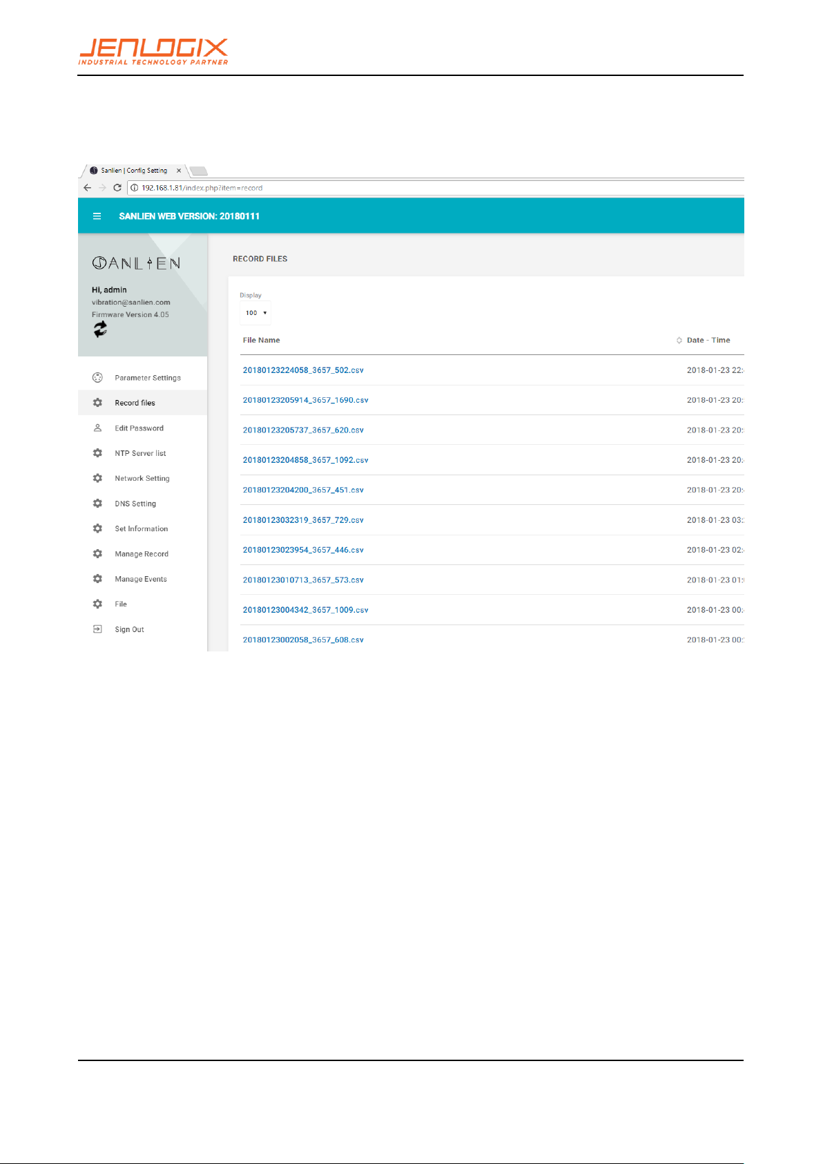
3.10 RECORD FILES
To view event files directly from web interface:
3.11 STREAMING
To check waveforms for all three axis it is possible to stream data. In addition this can be recorded for a specific
time.

PA LE RT A N D P X -0 1 SY ST EM S W EB
CO NF IG UR AT IO N
USER MANUAL
Jenlogix
Version 2 26/01/2018
© Jenlogix 2017 Jenlogix
Page 18 of 46
3.12 PARAMETERS SETTING TAB
The Parameters menu option is only available to the admin user.

PA LE RT A N D P X -0 1 SY ST EM S W EB
CO NF IG UR AT IO N
USER MANUAL
Jenlogix
Version 2 26/01/2018
© Jenlogix 2017 Jenlogix
Page 19 of 46
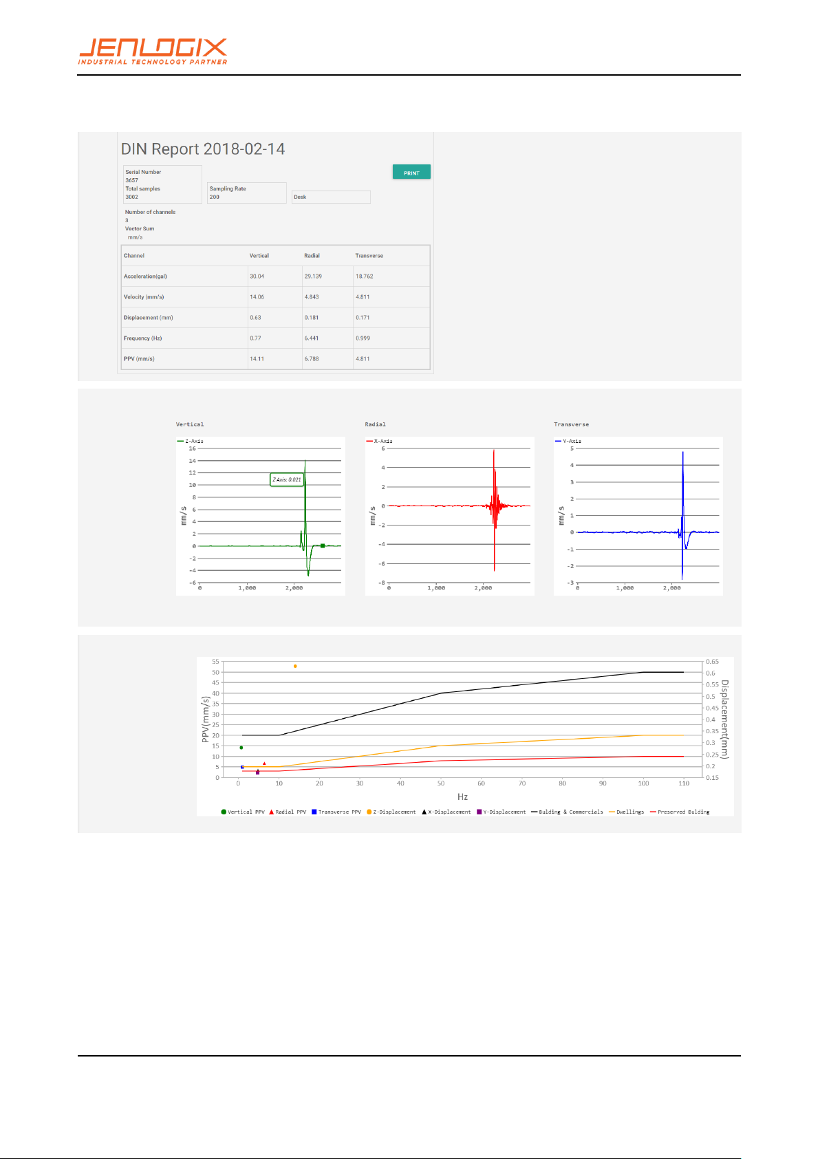
3.13 DIN REPORTS
Din provides details about vibration effects. There are 2 differnet reports – one a daily record and one a specific
record. Examples shown below
3.13.1 DIN REPORT
PA LE RT A N D P X -0 1 SY ST EM S W EB
CO NF IG UR AT IO N
USER MANUAL
Jenlogix
Version 2 26/01/2018
© Jenlogix 2017 Jenlogix
Page 20 of 46
3.13.2 DIN EVENT

PA LE RT A N D P X -0 1 SY ST EM S W EB
CO NF IG UR AT IO N
USER MANUAL
Jenlogix
Version 2 26/01/2018
© Jenlogix 2017 Jenlogix
Page 21 of 46
3.14 ISO REPORT
Shows vibrsation against the various standards of the ISO system both horizontal and vertical.

PA LE RT A N D P X -0 1 SY ST EM S W EB
CO NF IG UR AT IO N
USER MANUAL
Jenlogix
Version 2 26/01/2018
© Jenlogix 2017 Jenlogix
Page 22 of 46
3.15 DORTS REPORT
DORTS is the Dept of Rapid Transport Systems in Taipei and is similar to ISO
This shows various frequency plots 2/4/8/16/31.5/63 Hz, with multiple axis
…………..etc.

PA LE RT A N D P X -0 1 SY ST EM S W EB
CO NF IG UR AT IO N
USER MANUAL
Jenlogix
Version 2 26/01/2018
© Jenlogix 2017 Jenlogix
Page 23 of 46
4. PARAMETERS DESCRIPTION
Parameters can be broadly classified into (A) early warning parameters, (B) regional early warning parameters,
(C) parameters related to equipment and applications such as MQTT and firmware updates. Parameter
settings are based on vAlert8.cfg file i.e. the main configuration file of the unit. (Engineers Only)
Please refer to Palert Manual for further information on many of these parameters.
4.1.1 EARLY WARNING PARAMETERS
[PALERT_LOCAL_MODE]
SERIAL_NO
Serial number of the unit – normally should not be
changed.
LCD_BACK_LIGHT_SECOND
15
SERVER_IP
Server IP:port. Can have up to 3 servers.
MOUNT_MODE (Palert+)
WALL
OR
NORTHWARD (Normally not used)
OR
EASTWARD
SERVER_STREAM_MODE_TAIWAN
1
SERVER_PASSWORD
Server authentication password for CEB mode.
CEB_SEND_TIMEOUT_USEC
5000
MSEEDFILE_VALID_DAY
90
MODE
The streaming packet format, TAIWAN or CHINA mode.
CEB_MODE
Whether to adopt the China Seismological Bureau
protocol, YES / NO.
Station naming parameters for use with miniSeed file format especially
STATION_NET
Which network is the unit part of. E.g. NZ
STATION_NAME
Station name.

PA LE RT A N D P X -0 1 SY ST EM S W EB
CO NF IG UR AT IO N
USER MANUAL
Jenlogix
Version 2 26/01/2018
© Jenlogix 2017 Jenlogix
Page 24 of 46
STATION_CH_NAME
Station channel name for central server, such as HL.
STATION_CH_GEO_NAME
Additional name to handle areas
STATION_LOCATION
Station location for central server, such as 01.
STREAM_TRIG_PACKET
Sending trigger message or not.
STREAMING_IN_MSEC
Millisecond stream default 1000
SAMPLING_RATE
Sampling rate 50/100/200 sps.
VECTOR_INTENSITY
YES / NO
SPS_CH0
Samples per second Channel 0 Default 50
SPS_CH1
Samples per second Channel 1 Default 100
0SPS_CH2
Samples per second Channel 2 Default 200
FIR_MODE
Minimum phase filter (Only on low-pass filter) YES / No.
LPF
Low pass filter 10/20/40 Hz.
HPF
High-pass filter 0.1 / 0.3 / 0.5 / 1 Hz.
WATCH_TIME
Alert duration - seconds.
WARNING_TIME
Warning duration - seconds.
PD_TRIG_ENABLE
Use Pd threshold to trigger event YES / NO.
PD_WATCH_THRESHOLD
P-wave Pd displacement (cm) Alert threshold
Default 0.2
PD_WARNING_THRESHOLD
P-wave Pd displacement (cm) Warning threshold
Default 0.35
PGA_TRIG_ENABLE
Use PGA to trigger event YES / NO
PGA_WATCH_THRESHOLD
PGA (gal) watch threshold

PA LE RT A N D P X -0 1 SY ST EM S W EB
CO NF IG UR AT IO N
USER MANUAL
Jenlogix
Version 2 26/01/2018
© Jenlogix 2017 Jenlogix
Page 25 of 46
PGA_WARNING_THRESHOLD
PGA (gal) warning threshold
PGA_ACTION_THRESHOLD
PGA (gal) action threshold
STA_LTA_TRIG_ENABLE
Use STA / LTA to trigger event YES / NO.
STA_WIDTH
STA Time window (seconds)
LTA_WIDTH
Stop threshold of STA/LTA (seconds)
STA_LTA_THRESHOLD
STA / LTA ration trigger threshold.
STA_LTA_STOP_THRESHOLD
Time window of LTA (seconds)
STA_LTA_EVENT_TIME
STA / LTA trigger duration (seconds)
STA_LTA_RELAY1
RELAY1 Threshold unit: gal
STA_LTA_RELAY2
RELAY2 Threshold unit: gal
STA_LTA_RELAY3
RELAY3 Threshold unit: gal
S3_MODE
NO
AUTO_OFFSET
Use this function to move the moving average to zero or
not. YES/NO
INSTALLATION_ANGLE
Mounting angle correction from north 0 Clockwise is
positive.
INT_BATTERY_LOW_TH
Internal battery threshold: Default 3.5v
RTC_BATTERY_LOW_TH
Real Time Clock Battery threshold: Default 2.0v
EXT_POWER_LOW_TH
External Power threshold: Default 10 V
LCD_BACK_LIGHT_SECOND
Length of time backlight stays on
POWEROFF_SECONDS_TO_CPU
Length of time power remains to CPU on power off
CPU_STATUS_DISPLAY_INTERVAL
Length of time between CPU status displays

PA LE RT A N D P X -0 1 SY ST EM S W EB
CO NF IG UR AT IO N
USER MANUAL
Jenlogix
Version 2 26/01/2018
© Jenlogix 2017 Jenlogix
Page 26 of 46
WALL_MOUNT
Is unit Wall mounted?
RING_SECONDS
30
RING_CHANNELS
3
RING_FILTERED
NO
![WIRELESS_LAN_ENABLE]
NO
[NTP_RESET]
RESET_TH
2
ERR_IF_TIME_NOT_SYNC
YES
RTC_TO_SYSTEM_TIME
YES
![GEOPHONE]
Uncomment if using GEOPHONE
COMPENSATION
YES
[DISK_MIN_SPACE]
260000
[BACKUP_IP]
YES
[RESTORE_IP_WHILE_IP_ERROR]
YES
[LCD_RW_PIN_ENABLE]
YES
! Commented out optionally
DIN VERSION CONFIG ONLY:
[GEOPHONE]
!FREQ_START
!3
!FREQ_STOP
!6
!FREQ_STEP
!0.1
!G_START
!28

PA LE RT A N D P X -0 1 SY ST EM S W EB
CO NF IG UR AT IO N
USER MANUAL
Jenlogix
Version 2 26/01/2018
© Jenlogix 2017 Jenlogix
Page 27 of 46
!D_START
!0.7
!F_START
!4.5
! MASS_KG
0.011
[DIN_VIBRATION]
FFT_SECONDS
10
STRUCTURE_TYPE
2
DISPLAY_ON_LCD
YES
GEO_PHONE
NO
RECORD
YES
RECORD_ALWAYS
YES
WARNING_DB
-6
PGA_RELAY
NO
RELAY1_ON
NO
MAXIMUM_LATCH
To keep traffic light display on or auto off after 15
seconds YES/NO
!ADMIN_SERVER_IP
!
DORTS VERSION CONFIG ONLY:
[DORTS_VIBRATION]
BUILDING_TYPE
6
WARNING_DB
-6

PA LE RT A N D P X -0 1 SY ST EM S W EB
CO NF IG UR AT IO N
USER MANUAL
Jenlogix
Version 2 26/01/2018
© Jenlogix 2017 Jenlogix
Page 28 of 46
MAXIMUM_LATCH
YES
ISO VERSION CONFIG ONLY:
ISO_2631]
LOCATION_TYPE
2
MAXIMUM_LATCH
YES
4.1.2 OTHER PARAMETERS
[BACKUP_PROGRAM]
YES
SWITCH_UNLOCK_CODE
Key unlock code
ADMIN_SERVER_IP
Future use
MMI_INTENSITY
NO
BROADCAST_PORT
Future use
LCD_TITLE
Title on LCD
POWER_OFF_SWITCH_EXIST
Yes/No – future use
STREAM_TRIG_PACKET
Sending trigger message or not.
4.1.3 N OUT OF M SETTING
Note: Below are settings to add other Palerts for configuring 2 out of 3 system to eliminate the possibility of
false alarm (N out of M settings).
Currently N out of M is not implemented in Palert+ but only in PX-01 and Cube.
PALERT IP
Add 1 or multiple Palert or Palert+ IP.
MESSAGE PALERT
Which one will be the main Palert out of M Starting
from 0 – M.

PA LE RT A N D P X -0 1 SY ST EM S W EB
CO NF IG UR AT IO N
USER MANUAL
Jenlogix
Version 2 26/01/2018
© Jenlogix 2017 Jenlogix
Page 29 of 46
N WHERE N OUT OF M
N out of M Palerts, here add value for N.
M WHERE N OUT OF M
N out of M Palerts, here add value for M.
N OUT OF M IN SECOND
Acceptable time gap interval in secs, between the
triggered Palerts
N_OUT_OF_M_BY_MIDDLE
Event trigged while the number of trigged Palert +
greater than or equal to N.
The system in addition to providing local earthquake warning functions can also provide regional earthquake
early warning.
Alerts can be received using the public protocol (Common Alerting Protocol, CAP) earthquake early warning
messages.
4.1.4 REGIONAL WARNING SETTING
Parameters for regional early warning, used by Earthquake Early Warning System (EEWS) and shake map
central system, are as follows:
LOCAL_LONGITUDE
Longitude Unit: degrees
LOCAL_LATITUDE
Latitude of Unit: degrees
HEIGHT
Elevation of Unit: degrees
SITE EFFECT
To handle the site/geophysics effect.
This is a number that is generated from historic data
and defaults to 1.931. It should not normally be
changed.
EEWS SERVERS IP
EEWS Server IP address.
EEWS RELAY1 INTENSITY
Relay 1 trigger intensity threshold.
EEWS RELAY2 INTENSITY
Relay 2 trigger intensity threshold.
EEWS RELAY3 INTENSITY
Relay 3 trigger intensity threshold.
EEWS_HOLD_SECONDS
Keep alarm status after countdown

PA LE RT A N D P X -0 1 SY ST EM S W EB
CO NF IG UR AT IO N
USER MANUAL
Jenlogix
Version 2 26/01/2018
© Jenlogix 2017 Jenlogix
Page 30 of 46
4.1.5 VOICE ALARM AND EVENT RECORD
When the current threshold is met or a regional early warning is triggered, the system will start a voice alarm
playback. The threshold for the event to be recorded can be adjusted. Different voice alerts will be triggered
depending on the daytime / night time settings as follows.
DAY BEGIN MINUTE
Daytime start minute (420/60 = 7am).
DAY END MINUTE
Night starting time (1380/60 = 23 or 11pm).
EEWS DAY VOICE INTENSITY
Regional Day speech warning alert intensity threshold.
EEWS NIGHT VOICE INTENSITY
Regional warning voice alerts night intensity threshold.
DAY VOICEALARM-INTENSITY
Day voice alarm warning threshold intensity.
NIGHT VOICEALARM-INTENSITY
Night voice alarm warning threshold intensity.
VOICEALARM PLAY NUMBER
Number of times Voice broadcast repeats.
RECORD-INTENSITY
Start of recording seismic intensity threshold.
PRE-EVENT SECOND
The length of time before an incident that the data is
stored.
POST-EVENT SECOND
The amount of time after the incident that the data is
stored.
EVENT FILE MAX LENGTH IN SECOND
Longest time event is recoded. If not set, the default is
60 seconds.
4.1.6 MQTT PARAMETERS
MQTT (formerly Message Queue Telemetry Transport) is an ISO standard (ISO/IEC PRF 20922) publishsubscribe based "light weight" messaging protocol for use on top of the TCP/IP protocol. It is designed for
connections with remote locations where a "small code footprint" is required or the network bandwidth is
limited.
In addition to local warnings and regional warnings, Palert + can be used as an MQTT publisher, with the
earthquake warning message being shared to subscribers.

PA LE RT A N D P X -0 1 SY ST EM S W EB
CO NF IG UR AT IO N
USER MANUAL
Jenlogix
Version 2 26/01/2018
© Jenlogix 2017 Jenlogix
Page 31 of 46
[MQTT CONFIG]
IP
MQTT broker IP
You can use unit as local host 127.0.0.1.
PORT
MQTT Broker port.
USER
MQTT User Account
PASSWORD
MQTT User Password
LOCATION
MQTT location name
4.1.7 TEST MODE
The system can be put into test mode to check correct operation. This is for use by installation engineers
only.
Test mode parameter (Preset modes, do not modify)
TEST MODE CONFIG
Start test mode parameters
STAGE 0
Mode 0
SWITCH_SECOND 4
Pressing the power key for 4 Seconds enters test mode 0
RELAY_HOLD_SECOND
-5570590
5570590 = 0x0055001e
55-> 85 gal, 1e-> 30 seconds
PLAY_FILE 2.wav
Play audio files2.wav
RELAY2 ON
Drive RELAY2

PA LE RT A N D P X -0 1 SY ST EM S W EB
CO NF IG UR AT IO N
USER MANUAL
Jenlogix
Version 2 26/01/2018
© Jenlogix 2017 Jenlogix
Page 32 of 46
STAGE 1
Mode 1
SWITCH_SECOND 6
Pressing the power key for 6 Seconds enters test mode 1
RELAY_HOLD_SECOND 6
Drive RELAY for 6 seconds
PLAY_FILE 3.wav
Play audio files3.wav
RELAY1 ON
Drive RELAY1
STAGE 2
Mode 2
SWITCH_SECOND 8
Pressing the power key for 8 Seconds enters test mode 2
RELAY_HOLD_SECOND 8
Drive RELAY for 8 second
PLAY_FILE 4.wav
Play audio files4.wav
RELAY1 ON
Drive RELAY1
STAGE 3
Mode 3
SWITCH_SECOND 3
Pressing the power key for 3 Seconds to cancel the alarm
PLAY_FILE eewsCancel.wav
Plays audio files eewsCancel.wav..
4.1.8 FTP CONFIG
Unit firmware update function, generally do not need to modify.
IP
FTP Server IP
PORT
FTP Server port

PA LE RT A N D P X -0 1 SY ST EM S W EB
CO NF IG UR AT IO N
USER MANUAL
Jenlogix
Version 2 26/01/2018
© Jenlogix 2017 Jenlogix
Page 33 of 46
USER
FTP Server Username
PASSWORD
FTP Server User Password
4.1.9 SAVED FILE FORMAT
The default file format is csv, but it can be changed to mini seed format.
[EVENT_FILE_FORMAT]
mseed
4.1.10 RELAY CONTROL
(To be implemented)
[RELAY_BLINK_MODE]
To switch relay status on/off every second.
[RELAY_CONTROL_BY_ERR]
While system detects errors, drive the relay
[RELAY_RESET_BY_MANUAL]
Reset relay manually
[SINGLE_RELAY_MODE]
Event trigger after a relay trigger.
4.1.11 API
[API_CONFIG]
setup API parameter
EARTHQUAKE_FALLING_API
After the end of the event, driving API, Upload event
with record function.
4.1.12 UPLOAD AN EVENT RECORD
[VWHUB_CONFIG]
Upload an event record set parameter
FTPIP
FTP server IP

PA LE RT A N D P X -0 1 SY ST EM S W EB
CO NF IG UR AT IO N
USER MANUAL
Jenlogix
Version 2 26/01/2018
© Jenlogix 2017 Jenlogix
Page 34 of 46
FTPPORT
FTP server Port
USER
FTP server user account
PASSWORD
FTP server user Password
4.1.13 UPLOAD AN EVENT RECORD
[BROADCAST_PORT_INTERFACE]
If it’s set, the device will be through UDP Broadcast
transmission port area message, by default502.

PA LE RT A N D P X -0 1 SY ST EM S W EB
CO NF IG UR AT IO N
USER MANUAL
Jenlogix
Version 2 26/01/2018
© Jenlogix 2017 Jenlogix
Page 35 of 46
5. ACCESS OPERATING SYSTEM
To do underlying changes to the operating system configuration requires using terminal access. This can be
done with a product like Putty. Instructions as below.
5.1 INSTALL PUTTY OR SIMILAR ON
A LAPTOP
http://www.putty.org/
Change laptop IP to same newtwork as device
(192.168.255.xx - 20 as example).
Connect laptop to Device with normal Ethernet cable
Run putty and connect using SSH to IP address of unit
Accept security warning message
5.2 PASSWORD CHANGE
Using PUTTY login to the unit with the pi / 1111 default user
and password.
At prompt type passwd
Enter existing password
Then enter new password twice. This will need to be failry complex and not similar to previous as there are
password policies embedded in the system.
Type exit to leave system

PA LE RT A N D P X -0 1 SY ST EM S W EB
CO NF IG UR AT IO N
USER MANUAL
Jenlogix
Version 2 26/01/2018
© Jenlogix 2017 Jenlogix
Page 36 of 46
6. CHANGE VOICE ALARMS
On PX-01 devices it is possible to change the alarm messages. This requires using on the laptop/desktop an
ftp client like Winscp (https://winscp.net/eng/index.php ) or Filezilla. Winscp shown below.
• To change voice alarms, Connect using same user name / password as described in section 5
above with port 22. Then go to folder Desktop/vAlert8/bin.
• Voice alarms are stored in uncompressed .wav format. Optional default voices for Chinese and
English are stored in the wavChinese and wavEnglish subfolders.
• Default files can be copied from the subfolders to the bin folder replacing existing files.
• Optionally user can record their own voice alarms to replace the existing files using same file names.
e.g. .wav file used for Intensity now are named Intensity_x.wav where x is 1 to 12.

PA LE RT A N D P X -0 1 SY ST EM S W EB
CO NF IG UR AT IO N
USER MANUAL
Jenlogix
Version 2 26/01/2018
© Jenlogix 2017 Jenlogix
Page 37 of 46
7. CONTROL BUTTON
All devices have a control button that has several options depending how many seconds the button is pressed.
1. Display IP Address
2. Voice Test
3. Reset EEWS / Alarm Cancel
4. Reset Network / Reload by key
5. Test Mode Config Status
6. N/A
7. FTP update
8. N/A
9. Test Mode
10. N/A
11. N/A
12. Shutdown
The position of the boxes
7.1 BOOT INTERNAL DISPLAY
7.2 BOOT COMPLETE
The second line of the display will cycle through various information.

PA LE RT A N D P X -0 1 SY ST EM S W EB
CO NF IG UR AT IO N
USER MANUAL
Jenlogix
Version 2 26/01/2018
© Jenlogix 2017 Jenlogix
Page 38 of 46
7.3 OPTIONS
Press and hold the control button (2) to perform the functions below:
CUBE
PALERT+
PX-01

PA LE RT A N D P X -0 1 SY ST EM S W EB
CO NF IG UR AT IO N
USER MANUAL
Jenlogix
Version 2 26/01/2018
© Jenlogix 2017 Jenlogix
Page 39 of 46
7.3.1 HOLD FOR 1 SECONDS. DISPLAY IP
PA LE RT A N D P X -0 1 SY ST EM S W EB
CO NF IG UR AT IO N
USER MANUAL
Jenlogix
Version 2 26/01/2018
© Jenlogix 2017 Jenlogix
Page 40 of 46
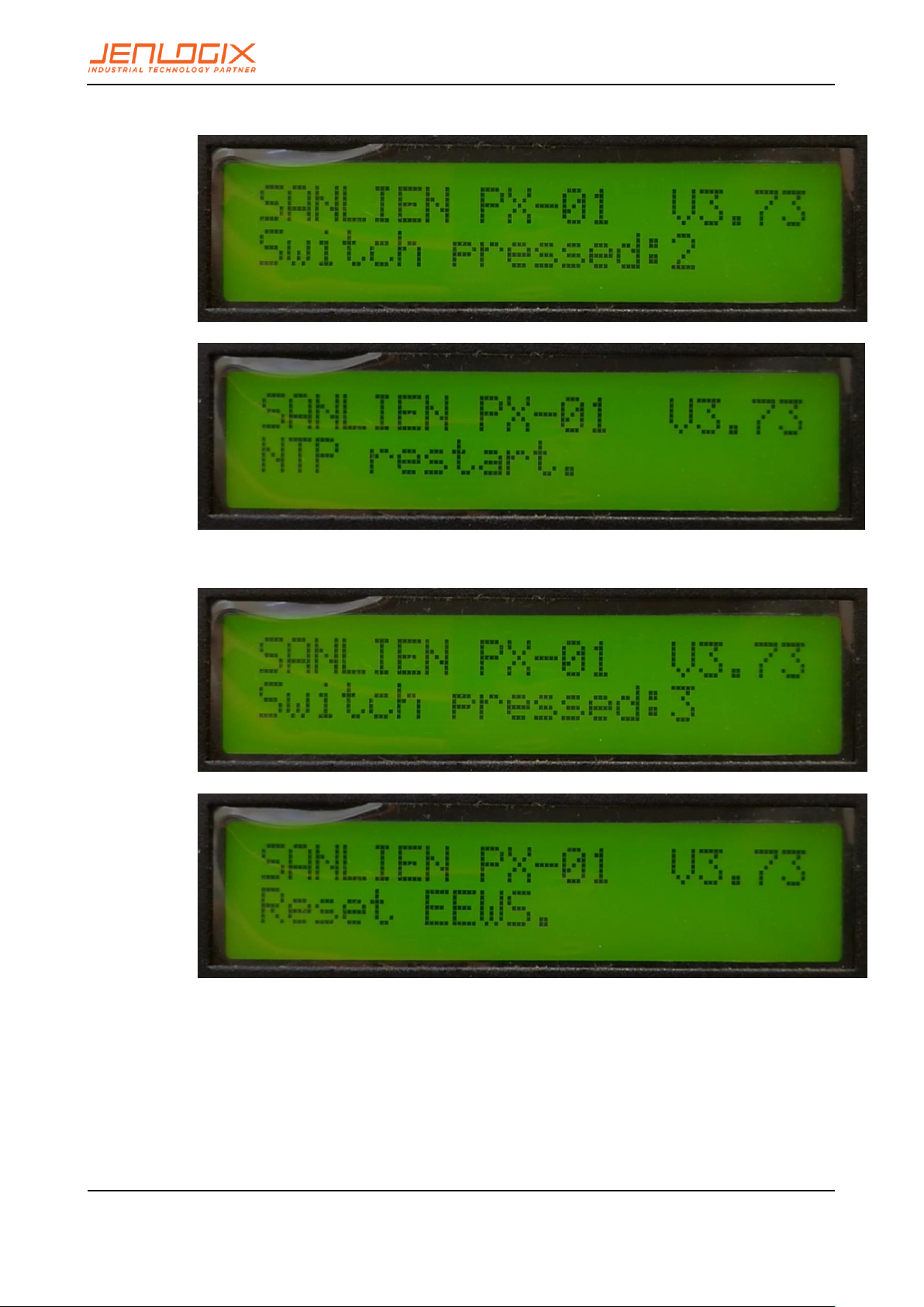
7.3.2 HOLD FOR 2 SEC. RESTART NTP
7.3.3 HOLD FOR 3 SEC. RESET WARNING

PA LE RT A N D P X -0 1 SY ST EM S W EB
CO NF IG UR AT IO N
USER MANUAL
Jenlogix
Version 2 26/01/2018
© Jenlogix 2017 Jenlogix
Page 41 of 46
7.3.4 HOLD FOR 4 SEC. RELOAD CONFIGURATION PARAMETERS
7.3.5 HOLD FOR 5 SECS. TEST MODE CONFIG STATUS
7.3.6 HOLD FOR 6 SECS
• No function.
PA LE RT A N D P X -0 1 SY ST EM S W EB
CO NF IG UR AT IO N
USER MANUAL
Jenlogix
Version 2 26/01/2018
© Jenlogix 2017 Jenlogix
Page 42 of 46
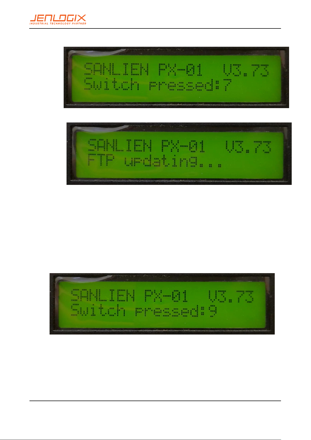
7.3.7 HOLD FOR 7 SECS. USE FTP UPDATE
7.3.8 HOLD FOR 8 SECS.
• No function.
7.3.9 HOLD FOR 9 SECS. ENTER TEST MODE
** This is for engineer usage only **

PA LE RT A N D P X -0 1 SY ST EM S W EB
CO NF IG UR AT IO N
USER MANUAL
Jenlogix
Version 2 26/01/2018
© Jenlogix 2017 Jenlogix
Page 43 of 46
Several test modes can be selected.
▪ Press the button for 4 seconds: test mode 0 – EEWS Test
▪ Press the button for 6 seconds: test mode 1 - on-site warning test level 3
▪ Press the button for 8 seconds: test mode 2- on-site warning test level 4
▪ Press the button for 3 seconds: test mode 3 – cancel
▪ Press 10 seconds to test all relays – intensity 1,3,5,7
7.3.10 HOLD FOR 10 SECS
• No function.
7.3.11 HOLD FOR 11 SECS.
• No function.
7.3.12 HOLD FOR 12 SECS TO SHUT DOWN.
** After selecting this option, the power must to be turned off to allow the system to be properly
restarted later **

PA LE RT A N D P X -0 1 SY ST EM S W EB
CO NF IG UR AT IO N
USER MANUAL
Jenlogix
Version 2 26/01/2018
© Jenlogix 2017 Jenlogix
Page 44 of 46

PA LE RT A N D P X -0 1 SY ST EM S W EB
CO NF IG UR AT IO N
USER MANUAL
Jenlogix
Version 2 26/01/2018
© Jenlogix 2017 Jenlogix
Page 45 of 46
8. MODBUS REGISTERS
These registers can be changed using a Modbus client for those that are not listed in the configuration file.
8.1 AO REGISTERS
UNIT Modbus AO Address Mapping Table (40XXX)
Register Description Note________________________________
113 data changed 0x0180 Reload parameters
0x0280 Clear rain gauge data
114 audio relay
100 EEWS Countdown test
101 EEWS Intensity test
8.2 AI REGISTERS
UNIT Modbus AI Address Mapping Table (300XXX)
Register Description Note________________________________
100 event
101 intensity now 0 ~ 7
102 PGA now 0.1gal
103 triggered Palerts [bit map]
104 Digital output status [bit map]
105 Digital input status [bit map]
106 system time in year
107 system time in month
108 system time in day
109 system time in weekday
110 system time in hour
111 system time in minute
112 system time in second
113 event time in year
114 event time in month
115 event time in day
116 event time in weekday
117 event time in hour
118 event time in minute
119 event time in second
120 connection status of Palert 0 ~ 4 [bit mapping]
121 connection status of fted04 0 ~ 4 [bit mapping]
122 connection status of board 0 ~ 4 [bit mapping]
123 connection status of ba host [bit mapping]
high nibble for zt2000
low nibble for ba host
Register Description Note________________________________

PA LE RT A N D P X -0 1 SY ST EM S W EB
CO NF IG UR AT IO N
USER MANUAL
Jenlogix
Version 2 26/01/2018
© Jenlogix 2017 Jenlogix
Page 46 of 46
124 UNIT version
125 connection status of DL-100 v2.06
126 DL-100 real time temperature // DL-100 Temperature and humidity sensor
127 DL-100 real time humidity
128 DL-100 average temperature
129 DL-100 average humidity
130 EEWS server connections status [bit mapping] v2.07
131 EEWS intensity
132 EEWS count down in second
133 zt2000DoStatus0_15 v3.03 Zigbee-based remote DO
134 zt2000DoStatus16_31
500 UNIT serial number 1 / 4 // v2.07
501 UNIT serial number 2 / 4
502 UNIT serial number 3 / 4
503 UNIT serial number 4 / 4
600 rain fall in counts within 1 minutes
601 rain fall in counts within 10 minutes
602 rain fall in counts within 1 hour
603 rain fall in counts within 12 hours
604 rain fall in counts within 1 day
605 rain fall in counts within 2 days
606 rain fall in counts within 3 days
607 rain fall in counts today
608 rain fall in counts yesterday
1000 ~ 1100 Palert0 packet header
2000 ~ 2100 Palert1 packet header
3000 ~ 3100 Palert2 packet header
4000 ~ 4100 Palert3 packet header
5000 ~ 5100 Palert4 packet header
please refer to Palert manual for contents of streaming packet
 Loading...