

Page 1
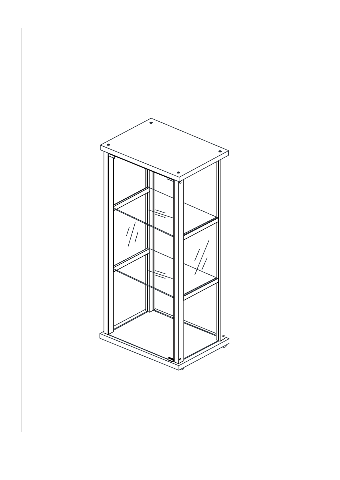
ASSEMBLY GUIDE
MODEL FSCC331614BL
Note:This instruction booklet contains important safety information,
please read and keep for future reference.
JENLEA INC.
Page 2
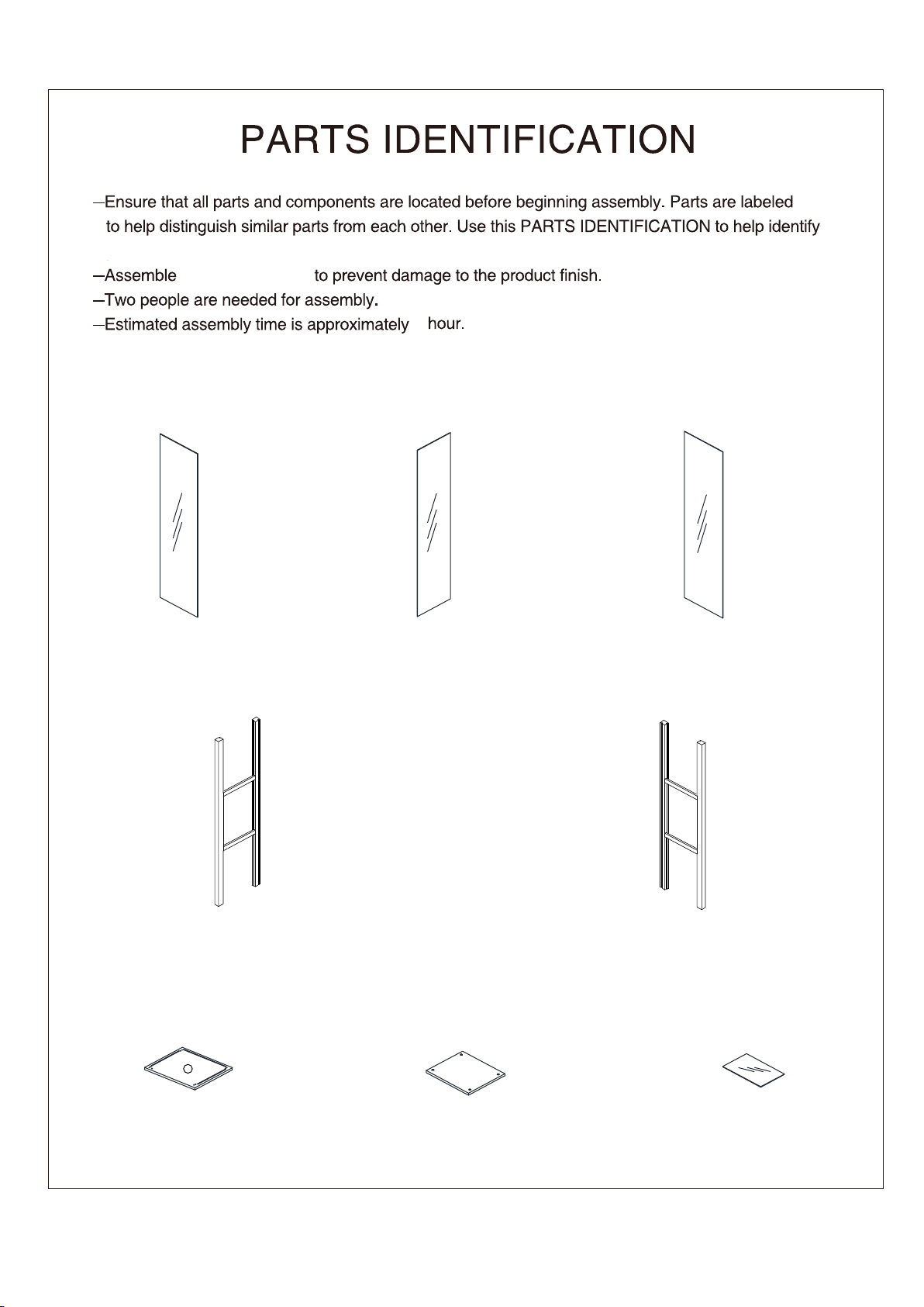
similar parts.
on a soft surface
1
DOOR GLASS-1PC
(A)
(DL) LEFT SHELF SUPPORT-1PC (DR) RIGHT SHELF SUPPORT-1PC
(B) SIDE GLASS-2PCS
(C) BACK GLASS-1PC
(E)
TOP PANEL-1PC
E
(F)
BOTTOM PANEL-1PC
--2--
(G)
SHELF GLASS-2PCS
Page 3
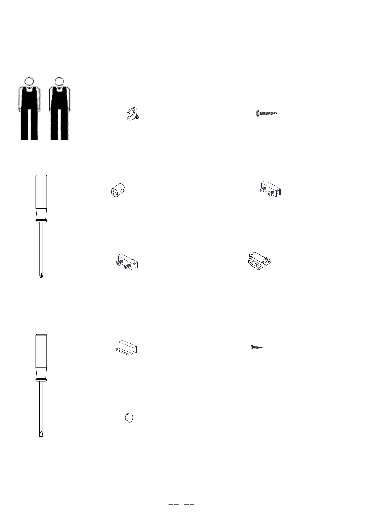
HARDWARE INDENTIFICATION
TOOL REQUIRED
(R1) ADJUSTABLE FOOT-4PCS
(R3) NUT-8PCS (R4) GLASS HINGE-1PC
(R5) GLASS HINGE-1PC
(R2) FLAT HEAD SCREW
ST4X40-8PCS
(R6) MAGNET-1PC
PHILLIPS HEAD
SCREWDRIVER
SHORT FLAT
SCREWDRIVER
(R7) LATCH PLATE-1PC
(R9) STICKER-12PCS
(R8) SCREW ST3X10-2PCS
3
Page 4
(R1) ADJUSTABLE FOOT
-4PCS
R1
R2
F
R1=4
R3
R9
(R2) FLAT HEAD SCREW
ST4X40-4PCS
(R3) NUT-4PCS
(R9) STICKER-4PCS
R2=4
R9=4
F
DL
R3=4
R3
DR
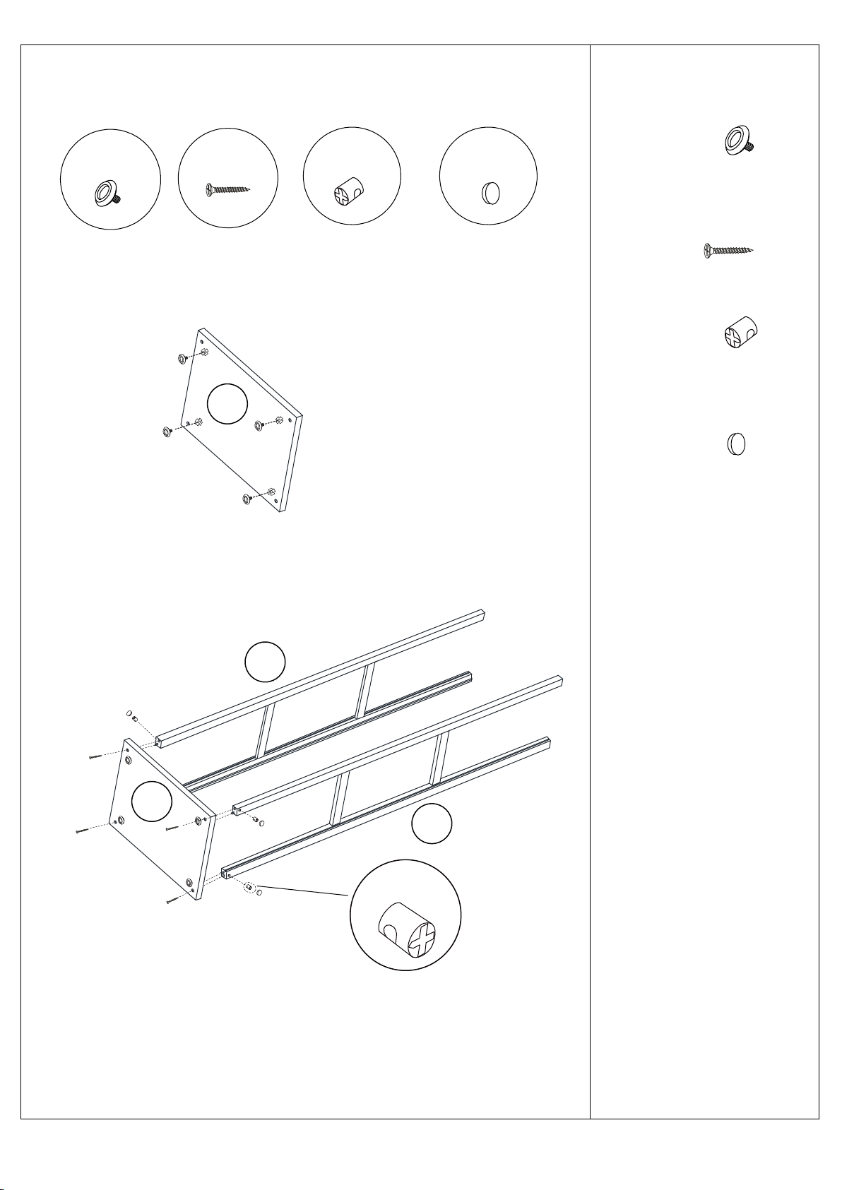
1.a)Fasten 4 adjustable
foot R1 to bottom panel F.
b)Fasten DL & DR to
bottom panel F, using 4 flat
head screw R2(ST4X40)
and 4 nut R3. Then put 4
sticker R9.
Note:Please install R3 as
shown on the photo with
arrow face to the direction
of R2 coming into join with.
--4--
Page 5
B
B
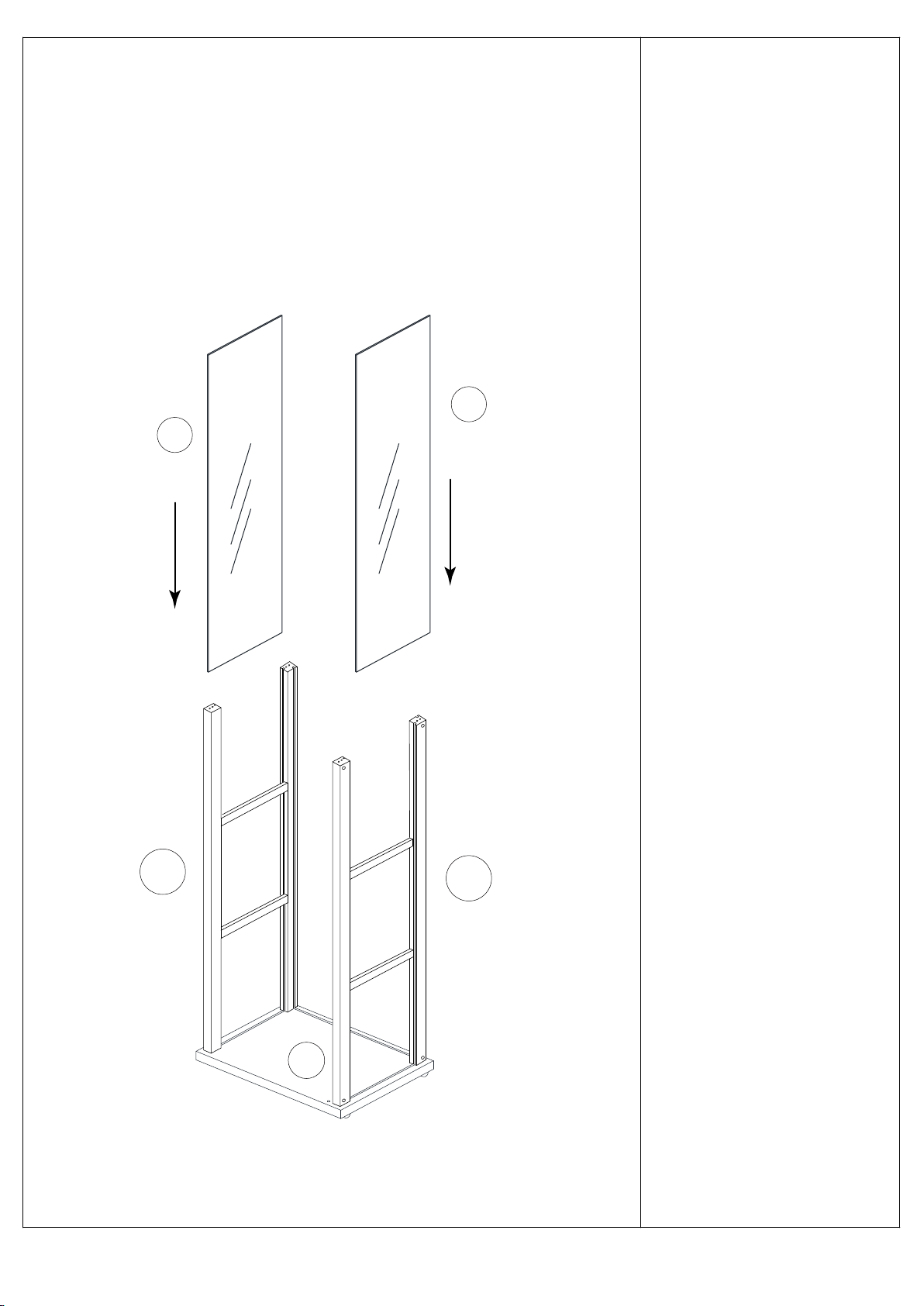
2.Slide the two side glass
B into the grooves in the
left shelf support DL, the
right shelf support DR,
and the bottom panel F.
DL
DR
F
--5--
Page 6
C
DL
B
F
B
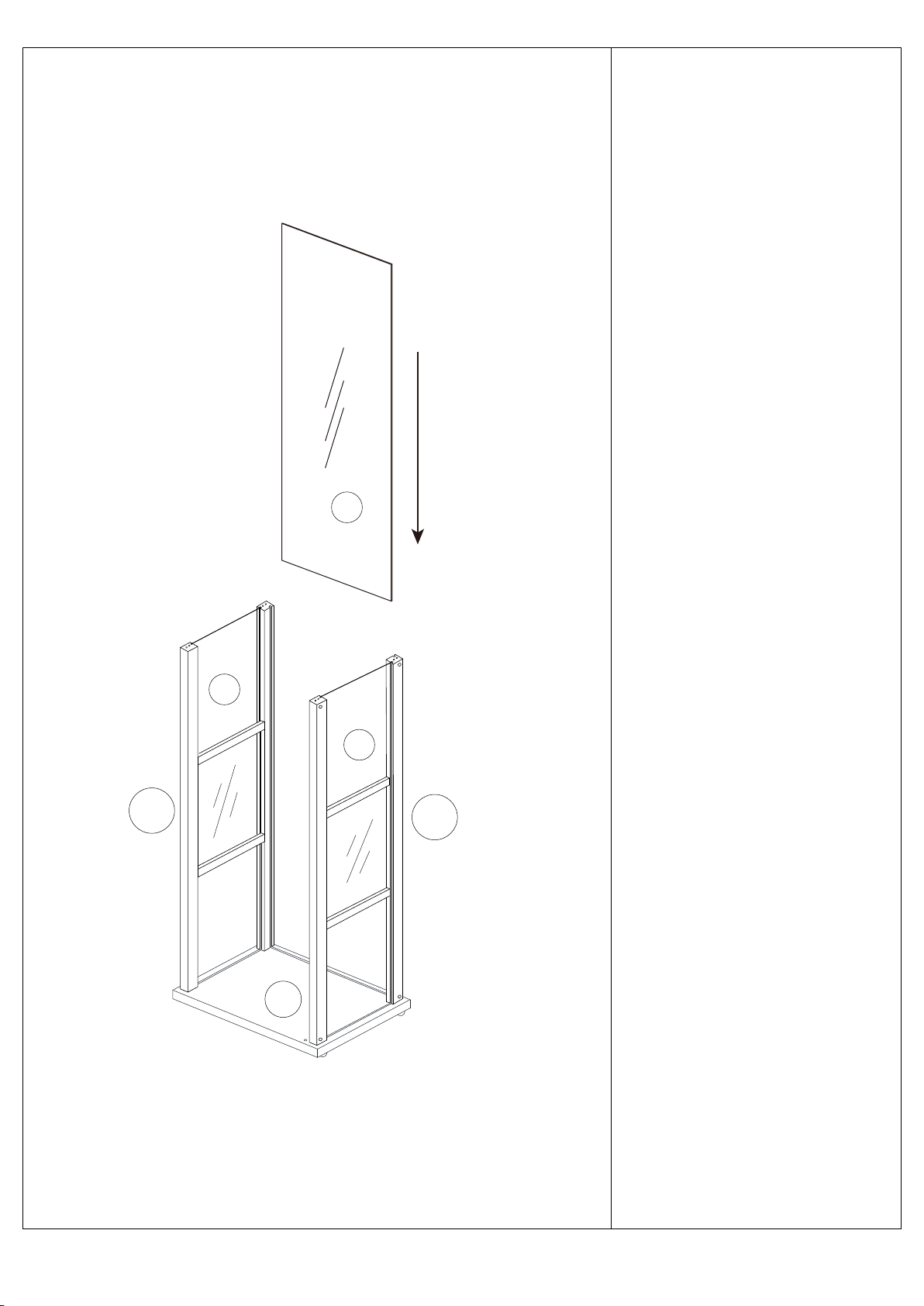
3.Slide the back glass C into
the grooves in the left shelf
support DL, the right shelf
support DR, and the bottom
panel F.
DR
--6--
Page 7
R2 R6R3
E
R8=2
R6=1
Note:This side faces
the glass door.
R9=4
R8
R9
(R2) FLAT HEAD SCREW
ST4X40-8PCS
(R3) NUT-8PCS
(R6) MAGNET-1PC
(R8) SCREW ST3X10-2PCS
(R9) STICKER -8PCS
R9=4
R3=4
DL
B
E
C
B
R2=4
DR
R3
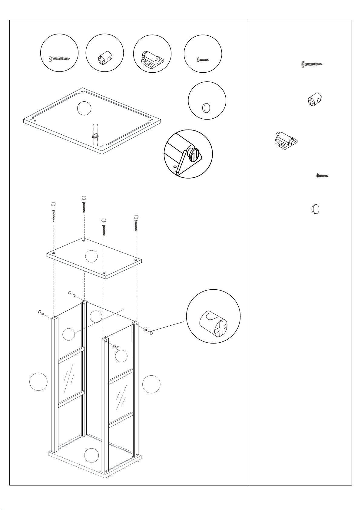
4. a)Fasten 1 magnet R6 to
top panel E with 2 screw R8
(ST3X10).
b)Fasten top panel E to
DL & DR, using 4 flat head
screw R2(ST4X40) and 4 nut
R3. Then put 8 sticker R9.
Note:a)Please install R3 as
shown on the photo with
arrow face to the direction
of R2 coming into join with.
b)The magnet is adjustable,
please make sure it is in the
right place to attach the door
closely.
F
--7--
Page 8
G
E
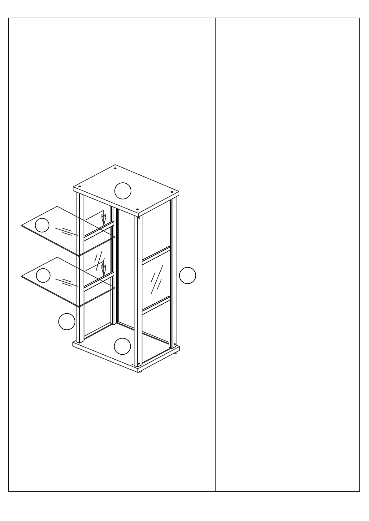
5.Put 2 shelf glass G on the
side shelf support of DL & DR.
G
DR
DL
F
--8--
Page 9
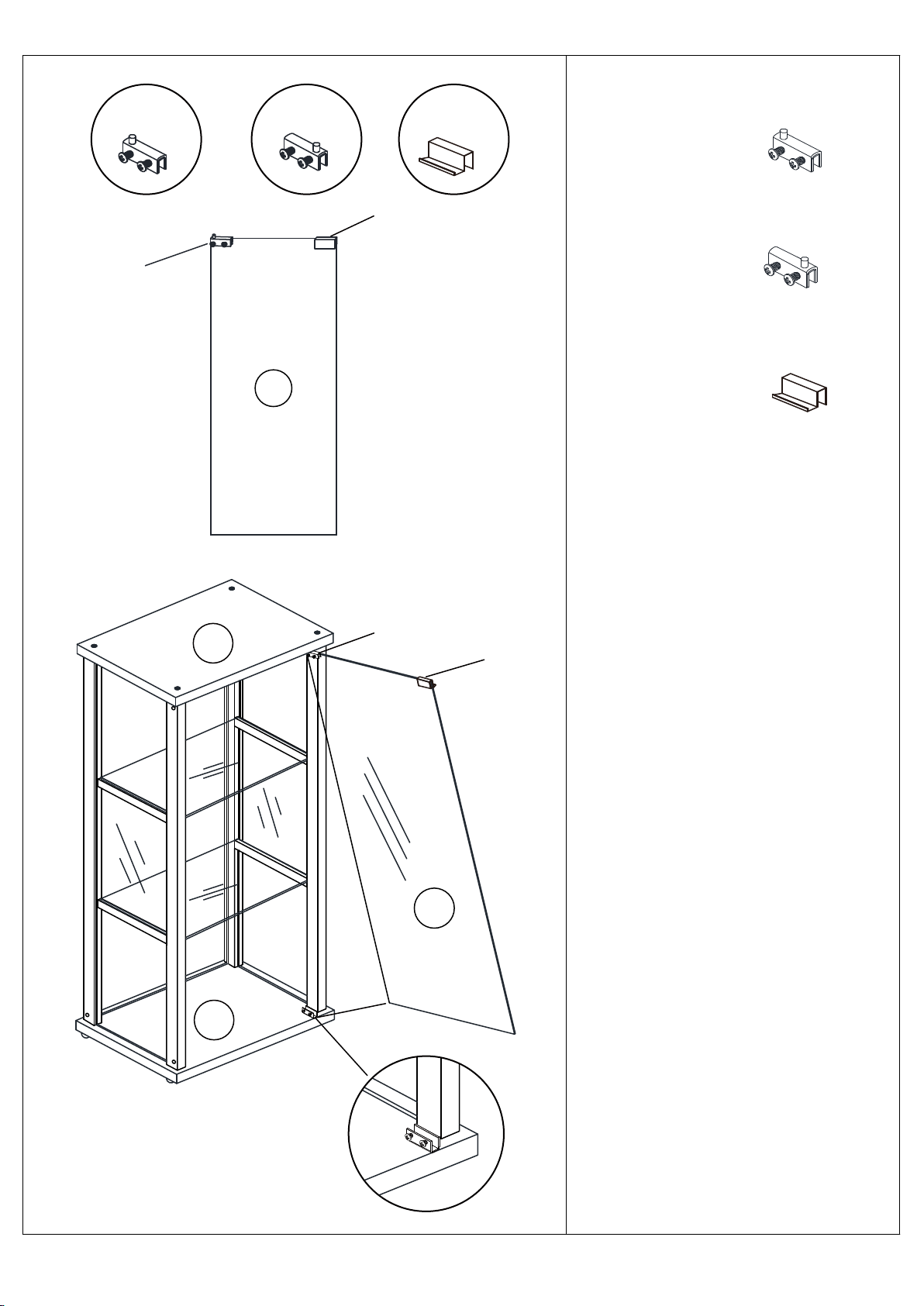
R4 R5
R7
(R4) GLASS HINGE-1PC
R4=1
E
A
R7=1
R4
R7
(R5) GLASS HINGE-1PC
(R7) LATCH PLATE-1PC
6.a)First fasten 1 latch plate R7
and 1 glass hinge R4 on the
corners of door glass A.
b)Insert glass hinge R5 into the
hole on bottom panel F.
F
c)Insert glass hinge R4 into the
hole on top panel E.
d)Slide the glass into R5, then
fasten the screws.
Note:You can loose all screws and
A
move the glass slightly to make
tightly, just squeeze it.
R4/R5/R7 in right position if latch
plate R7 can’t touch magnet
properly. If R7 can’t hold the glass
R5=1
--9--
 Loading...