

Page 1
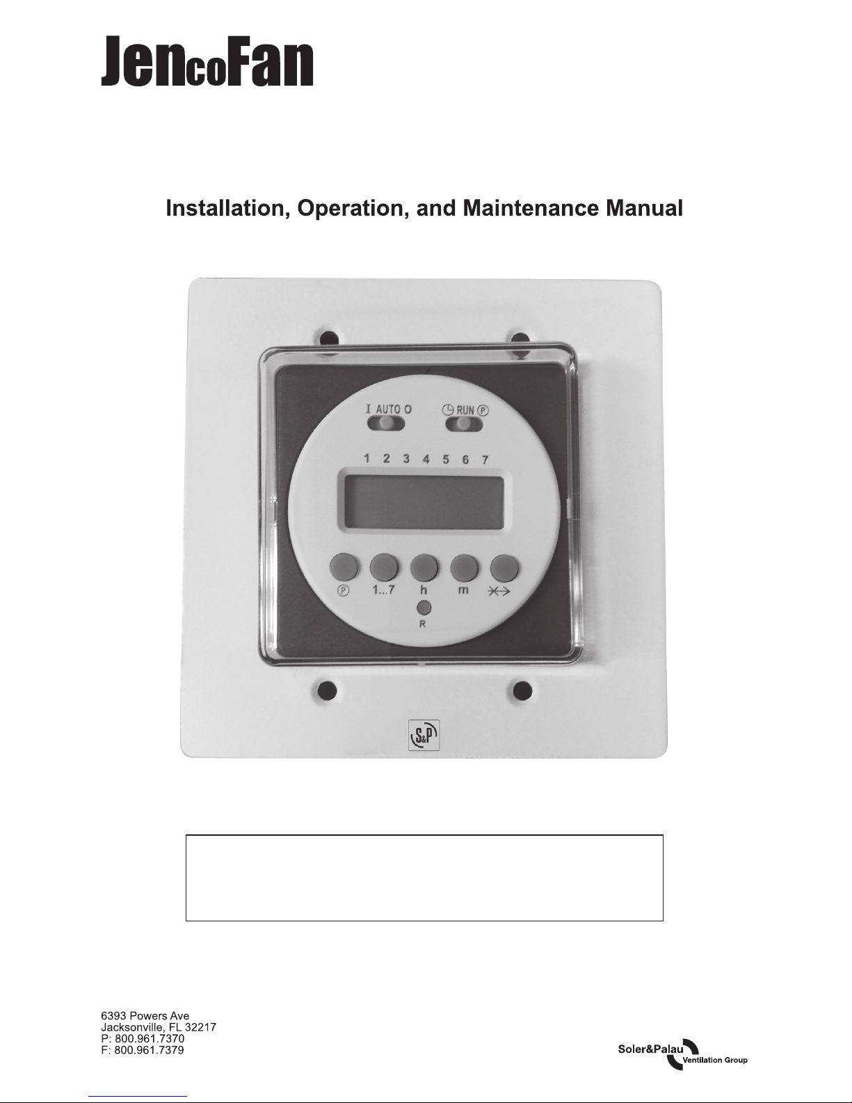
Installation, Operation, and Maintenance Manual
Installation, Operation, and Maintenance Manual
READ AND SAVE THESE INSTRUCTIONS
The purpose of this manual is to aid in the proper installation and operation of fans
manufactured by S&P USA. These instructions are intended to supplement good
general practices and are not intended to cover detailed instruction procedures,
because of the wide variety and types of fans manufactured by S&P USA.
6393 Powers Ave
Jacksonville, FL 32217
P: 800.961.7370
F: 800.961.7379
STC7D-IOM_v.1 / 09-2018
STC7D
Digital Time Clock for TRC500 & TRC800
READ AND SAVE THESE INSTRUCTIONS
The purpose of this manual is to aid in the proper installation and operation of fans
manufactured by JencoFan.These instructions are intended to supplement good
general practices and are not intended to cover detailed instruction procedures,
because of the wide variety and types of fans manufactured by JencoFan.
Page 2

Page 3
1
Installation Instructions
STC7D
1. WARNINGS
READ AND SAVE THESE INSTRUCTIONS. FAILURE TO
COMPLY WITH INSTRUCTIONS COULD RESULT IN PERSONAL INJURY AND/OR
PROPERTY DAMAGE!
WARNING: TO REDUCE THE RISK OF FIRE, ELECTRIC SHOCK OR INJURY, OBSERVE THE
FOLLOWING:
1. Use this unit only in the manner intended by the manufacturer. If you have questions, contact
the manufacturer.
2. Before installing, servicing or troubleshooting the transformer/relay package, switch power o
at service panel and lock service panel to prevent power from being switched onaccidentally.
CAUTION: more than one disconnect switch may be required to de-energize the equipment for
servicing.
3. Installation work and electrical wiring must be done by qualied person(s) in accordance with all
applicable codes and standards, including re-rated construction.
4. When cutting or drilling into wall or ceiling, do not damage electrical wiring and other hidden
utilities.
5. NEVER place a switch where it can be reached from a tub or shower.
6. Intended for use with 24VAC Class 2 power supplies only.
7. Do not connect loads that exceed the timer’s switch rating.
8. Conrm sucient 24VAC power is available to operate the timer and the connected loads.
2. SPECIFICATIONS
Operating Voltage 24VAC 50/60Hz
Switching
Single Pole, Single Throw [SPST] (can be eld-modied to Single Pole,
Double Throw [SPDT])
Power Consumption 3.5VA
Switch Rating 10 Amps at 131°F
Operating
Temperature Range
14°F – 131°F
Connections
(STC7D-W)
(3) 16 GA pigtails (wire nuts not provided)
Backup Power
Lithium battery with minimum 5-year reserve, 10-year projected life, not
eld-replaceable
Setting Options
• 8 pairs of on-o time of day cycles can be programmed.
• Each on-o cycle can be assigned to any one day of the week, or to
the following groups of days:
• Monday – Friday; Monday – Saturday; Monday – Sunday; Saturday
and Sunday.
• Manual Over-ride provided by “On/Auto/O” switch.
• Program Reset button clears all settings.
Enclosure
(STC7D-W)
Requires a 4” x 4” electrical box by others.
Box must accommodate (4) mounting screws (see drawing).
Minimum box depth 1.5”. White wall plate and mounting screws provided.
Page 4
2
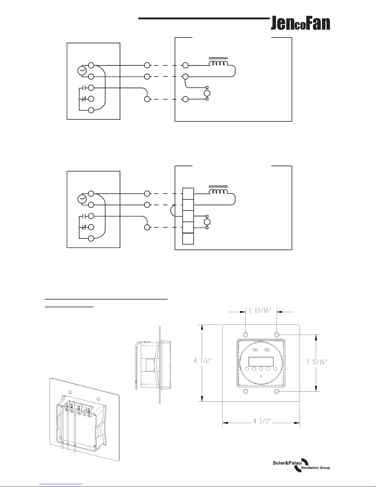
3. CONNECTION DIAGRAM
Applicable to TRC500 and TRC800 models
STC7D-W showing plate dimensions and
screw spacings.
1
2
3
4
5
C
C
YEL
YEL
YEL
BLUERED
RED
ERV INTERNAL CONTROL
WIRING (SIMPLIFIED)
ERV INTERNAL CONTROL
WIRING (SIMPLIFIED)
Unit’s 24VAC
Power Supply
Isolation
Relay Coil
Unit’s 24VAC
Power Supply
Isolation
Relay Coil
The Normally Closed contacts of one or
more additional Low V oltage Controls may
be connected to E RV unit in parallel with
the STC&D-W.
The Normally Closed contacts of one or
more additional Low V oltage Controls may
be connected to E RV unit Terminals 1 &
4. Do not apply power to these terminals.
BLACK
STC7D-W
1
2
3
4
5
YEL
1
2
3
4
5
RED
BLACK
STC7D-W
Page 5
3
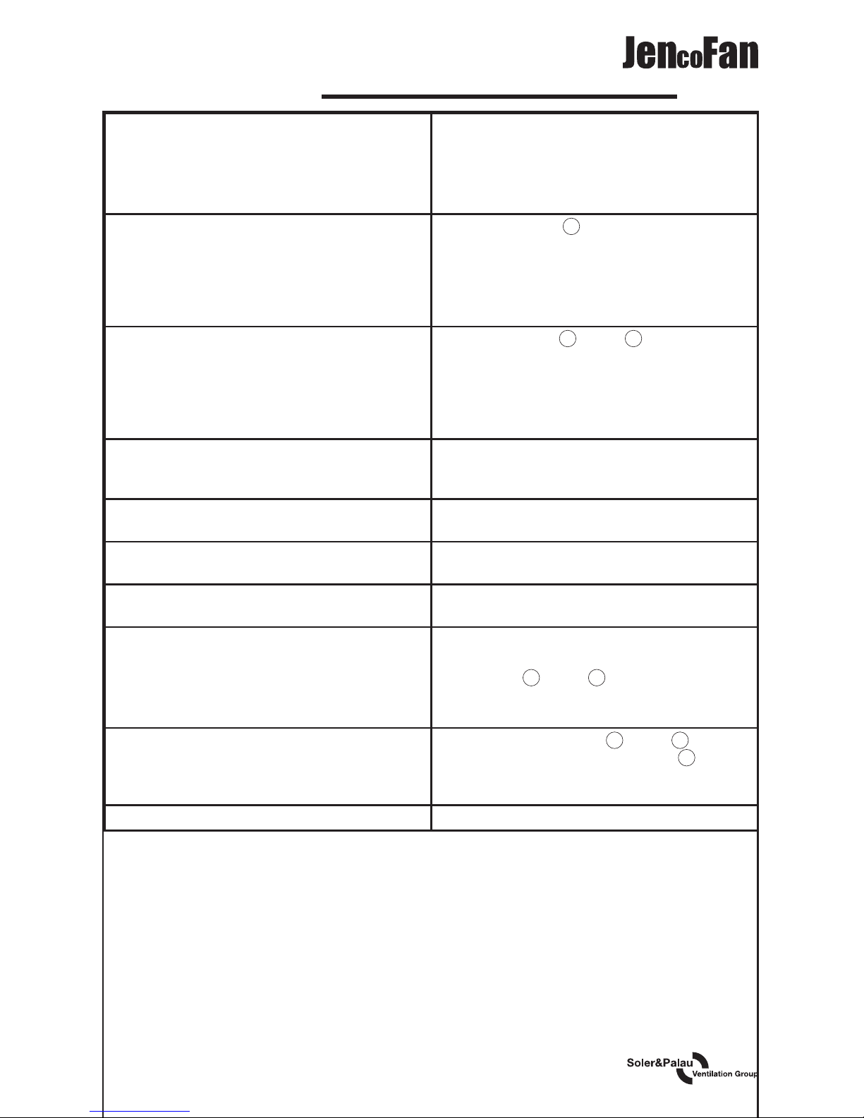
4. SETTING INSTRUCTIONS
Set Time and Day
Slide Set switch to press 1…7 button until
arrow points to the correct day (1=Monday).
Press h then m buttons to set correct time. PM
indicator shows noon to 11:59 PM. Slide Set
switch to Run. Clock colon will blink.
Set Switch “On” Cycle
Slide Set switch to P . A “1” indicates the rst
switch cycle and a “Bulb” indicates a switch-on
(circuit closes). Press 1…7 button until arrows
point to selected day(s) for this cycle. Press h
and m buttons to show switch-on time, noting
PM indicator.
Set Switch “O” Cycle
With Set switch at P , press P button, note
switch cycle number changes to “2” and Bulb
blinks, indicating switch-o (circuit opens).
Press 1…7 button to match day(s) set for switch
cycle “1”. Press h and m buttons to select
switch-o time.
Autorun
Slide Set switch to Run and Mode switch to
Auto, switching begins with next switch-on set
time.
Override “On”
Slide Mode switch to "I". Switch remains on
indenitely (circuit closed).
Override “O”
Slide Mode switch to "O". Switch remains on
indenitely (circuit open).
Skip Cycle
In automatic run mode, press "x→" button. The
next calendar day is skipped.
Setting ERROR
If EEE appears, a setting error exists. The
switch cycle number in error is shown. Slide
set switch to P , press P button until cycle is
shown, review this and the following setting to
correct error, slide set switch to Run.
Clear any setting
Setting slide set switch to P , press P button to
show switch cycle to clear. Press the P button
and the skip (x) button simultaneously, hold for
several seconds.
Clear All To erase all settings, Press "R".
Page 6

 Loading...