

Jenbacher DIANE.XT User Manual
1 of 87
CHECK WITH LOCAL UTILITIES
FOR RELAY AND
SYNCHRONIZER APPROVALS
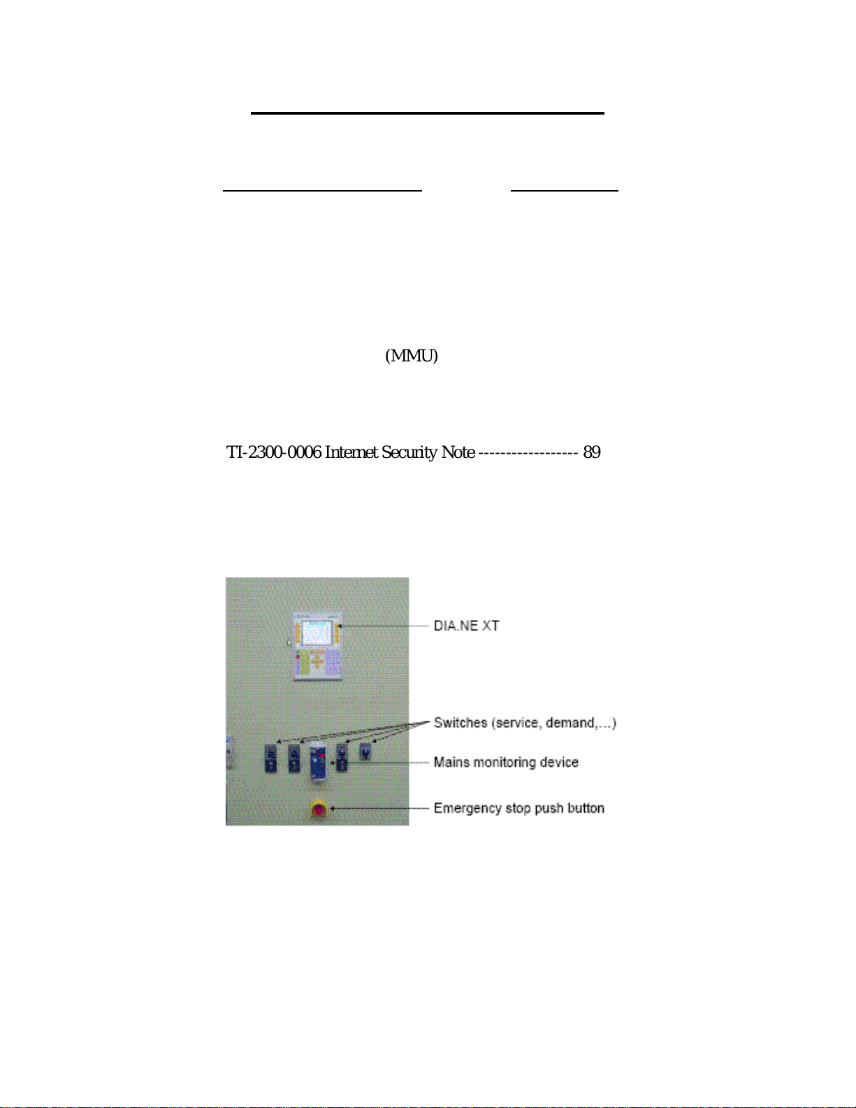
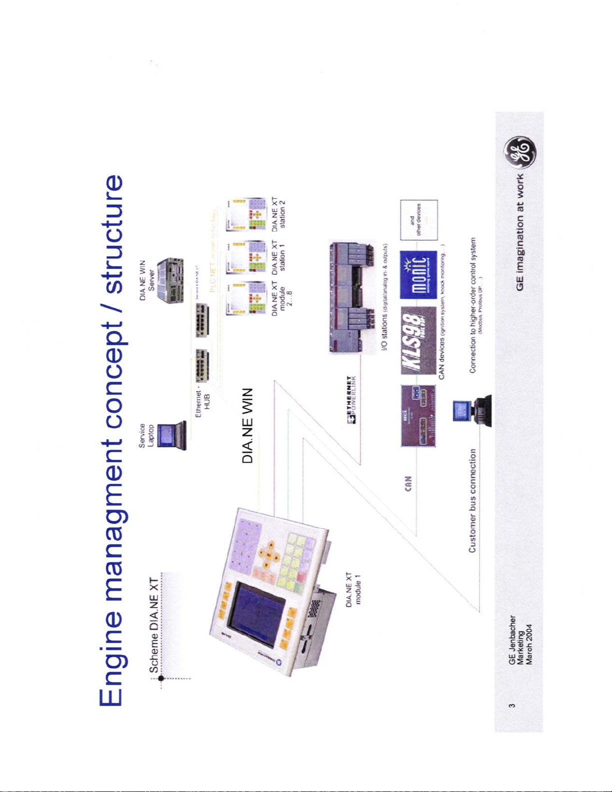
Jenbacher DIA.NE XT Control
Description of Document Page Number
DIA.NE XT (General Description) --------------------- 3
Table of Contents ------------------------ 4
Mains Monitoring Relay (SEG – MRN3) ------------- 17
Table of Contents ----------------------- 18
Synchronizing Module (MMU) ------------------------- 57
DIA.NE WIN (General Description) ------------------ 77
Table of Contents ----------------------- 78
TI-2300-0006 Internet Security Note ------------------ 89
Up-Dated October 2010

2 of 87
Blank Page for Notes

3 of 87
4 of 87
5 of 87
6 of 87
7 of 87
8 of 87
9 of 87
10 of 87
11 of 87
12 of 87
13 of 87
14 of 87
15 of 87

16 of 87
Blank Page for Notes
17 of 87
MRN3
Mains decoupling relay
-

Contents
18 of 87
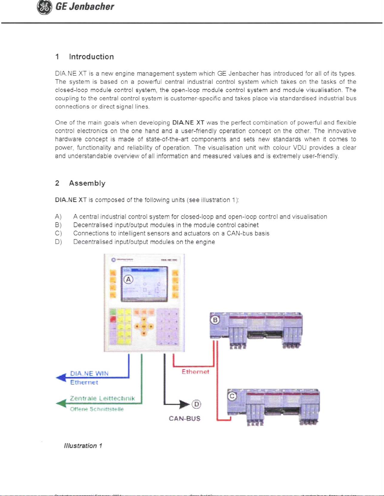
1 Introduction and application
2 Features and characteristics
3 Design
3.1 Connections
3.1.1 Analog input circuits
3.1.2 Blocking input
3.1.3 Reset input
3.1.4 Output relays
3.1.5 Fault recorder
3.2 Parameter settings
3.3 LEDs
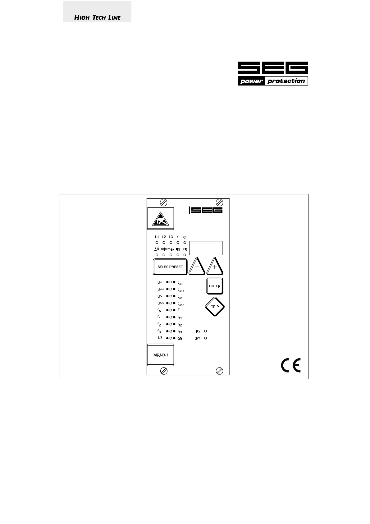
3.4 Front plate
4 Working principle
4.1 Analog circuits
4.2 Digital circuits
4.3 Voltage supervision
4.3.1 Selection of star or delta connection
4.4 Principle of frequency supervision
4.5 Measuring of frequency gradient (MRN3-2)
4.6 Vector surge supervision (MRN3-1)
4.6.1 Measuring principle of vector surge
supervision
4.7 Voltage threshold value for frequency
measuring
4.8 Blocking function
5 Operation and setting
5.1 Display
5.2 Setting procedure
5.3 Systemparameter
5.3.1 Display of residual voltage U
quantity (U
prim/Usec
)
as primary
E
5.3.2 ∆/Y – Switch over
5.3.3 Setting of nominal frequency
5.3.4 Display of the activation storage
(FLSH/NOFL)
5.3.5 Parameterswitch/external trigger for the
fault recorder
5.4 Protection parameters
5.4.1 Parameter setting of over- and under voltage supervision
5.4.2 Number of measuring repetitions (T) for
frequency functions
5.4.3 Threshold of frequency supervision
5.4.4 Tripping delays for the frequency elements
5.4.5 Parameter setting of vector surge
supervision (MRN3-1)
5.4.6 Parameter setting of frequency gradient
(MRN3-2)
5.4.7 Voltage threshold value for frequency
and vector surge measuring (df/dt at
MRN3-2)
5.4.8 Adjustment of the slave address
5.4.9 Setting of Baud-rate (applies for Modbus
Protocol only)
5.4.10 Setting of parity (applies for Modbus
Protocol only)
5.5 Adjustment of the fault recorder
5.5.1 Number of the fault recordings
5.5.2 Adjustment of trigger occurences
5.5.3 Pre-trigger time (T
)
pre
5.6 Adjustment of the clock
5.7 Additional functions
5.7.1 Setting procedure for blocking the
protection functions
5.8 Indication of measuring values
5.8.1 Measuring indication
5.8.2 Min./Max.- values
5.8.3 Unit of the measuring values displayed
5.8.4 Indication of fault data
5.9 Fault memory
5.9.1 Reset
5.9.2 Erasure of fault storage
2 TD_MRN3_08.03_GB

19 of 87
6 Relay testing and commissioning
6.1 Power-On
6.2 Testing the output relays
6.3 Checking the set values
6.4 Secondary injection test
6.4.1 Test equipment
6.5 Example of test circuit
6.5.1 Checking the input circuits and
measuring functions
6.5.2 Checking the operating and resetting
values of the over/undervoltage functions
6.5.3 Checking the relay operating time of the
over/undervoltage functions
6.5.4 Checking the operating and resetting
values of the over/underfrequency
functions
6.5.5 Checking the relay operating time of the
over/underfrequency functions
6.5.6 Checking the vector surge function
6.5.7 Checking the external blocking and reset
functions
6.6 Primary injection test
6.7 Maintenance
7 Technical data
7.1 Measuring input circuits
7.2 Common data
7.3 Setting ranges and steps
7.3.1 Interface parameter
7.3.2 Parameters for the fault recorder
7.4 Output relays
8 Order form
TD_MRN3_08.03_GB 3

1 Introduction and application
20 of 87
The MRN3 is a universal mains decoupling device
and covers the protection requirements from VDEW
and most other utilities for the mains parallel operation
of power stations.
• Over/ and undervoltage protection,
• over/ and underfrequency protection,
• extremely fast decoupling of generator in case of
mains failure (MRN3-1) or
• rate of change of frequency df/dt (MRN3-2)
Because of combination of three protectional functions
in one device the MRN3 is a very compact mains de-
coupling device. Compared to the standardly used
single devices it has a very good price/performance
ratio.
For applications where the single protection functions
are required SEG can offer the single MR-relays as follows:
• MRU3-1 four step independent over-/ and under-
voltage protection (also used for gene rator earth fault protection).
• MRU3-2 two step independent over-/ and under-
voltage protection with evaluation of the
symmetrical voltage components.
• MRF3 four step independent over/ and under-
frequency protection and two step
frequency gradient supervision df/dt.
• MRG2 generator mains monitor / vector surge
detection.
Important:
For additional common data of all MR-relays please
refer to technical description "MR - Digital Multifunctional Relays".
2 Features and characteristics
• Microprocessor technology with watchdog,
• effective analog low pass filter for suppressing har-
monics when measuring frequency and vector surge,
• digital filtering of the measured values by using dis-
crete Fourier analysis to suppress higher harmonics
and d.c. components induced by faults or system
operations,
• integrated functions for voltage, frequency and vec-
tor surge in one device as well as single voltage,
frequency and vector surge devices,
• two parameter sets,
• voltage supervision each with two step under-/and
overvoltage detection,
• frequency supervision with three step under-/or
overfrequency (user setting),
• completely independent time settings for voltage and
frequency supervision,
• adjustable voltage threshold value for blocking fre-
quency and vector surge measuring,
• display of all measuring values and setting parame-
ters for normal operation as well as tripping via a
alphanumerical display and LEDs,
• display of measuring values as primary quantities
• Storage of trip values and switching-off time (t
5 fault occurences (fail-safe of voltage),
• recording of up to eight fault occurences with time
stamp
• for blocking the individual functions by the external
blocking input, parameters can be set according to
requirement,
• user configurable vector surge measurement 1-of-3
or 3-of-3,
• reliable vector surge measuring by exact calculation
algorithm,
• suppression of indication after an activation
(LED flash),
• free assignment for output relays,
• display of date and time,
• in complience with VDE 0435, part 303 and IEC
255,
• serial data exchange via RS485 interface possible;
alternatively with SEG RS485 Pro-Open Data Protocol or Modbus Protocol.
CBFP
) of
4 TD_MRN3_08.03_GB
3 Design
21 of 87
3.1 Connections
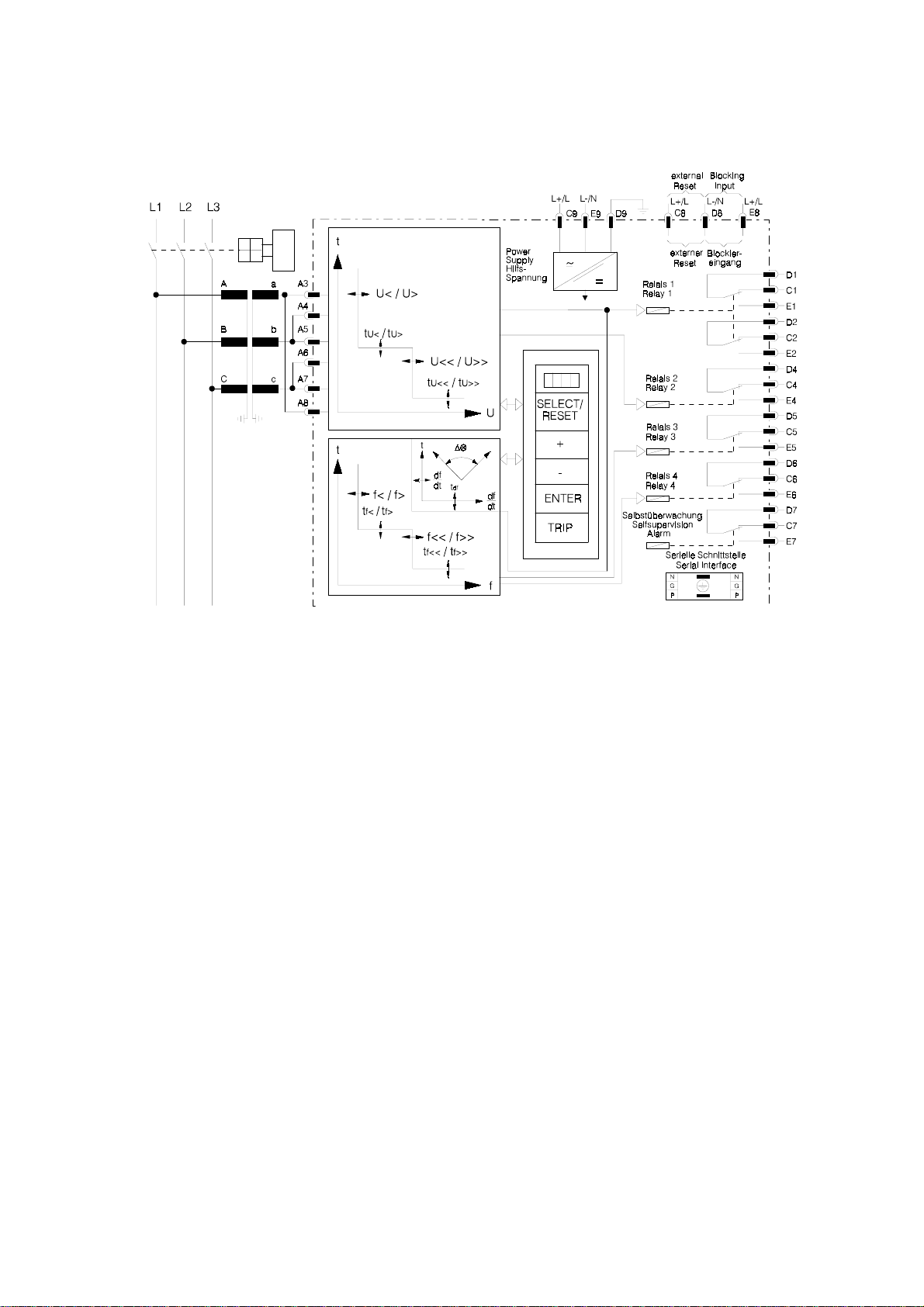
Figure 3.1: Connection diagram MRN3-1 and MRN3-2
3.1.1 Analog input circuits
The analog input voltages are galvanically decoupled
by the input transformers of the device, then filtered
and finally fed to the analog digital converter. The
measuring circuits can be applied in star or delta connection (refer to chapter 4.3.1).
3.1.2 Blocking input
The blocking function can be set according to requirement. By applying the auxiliary voltage to
D8/E8, the previously set relay functions are blocked
(refer to 4.8 and 5.7.1).
3.1.3 Reset input
Please refer to chapter 5.9.1.
3.1.4 Output relays
The MRN3 is equipped with 5 output relays. Apart
from the relay for self-supervision, all protective functions can be optionally assigned:
• Relay 1: C1, D1, E1 and C2, D2, E2
• Relay 2: C3, D3, E3 and C4, D4, E4
• Relay 3: C5, D5, E5
• Relay 4: C6, D6, E6
• Relay 5: Signal self-supervision (internal failure of the
unit ) C7, D7, E7
All trip and alarm relays are working current relays,
the relay for self supervision is an idle current relay.
TD_MRN3_08.03_GB 5
3.1.5 Fault recorder
22 of 87
The MRN3 has a fault value recorder which records
the measured analog values as instantaneous values.
The instantaneous values
U
or U
; UL2; UL3 for star connection
L1
; U23; U21 for delta connection
12
are scanned at a raster of 1.25 ms (at 50 Hz) and
1.041 ms (at 60 Hz) and saved in a cyclic buffer. It is
possible to store 1 - 8 fault occurences with a total recording time of 16 s (with 50 Hz) and 13.33 s (with
60 Hz) per channel.
Storage division
Independent of the recording time, the entire storage
capacity can be divided into several cases of disturbance with a shorter recording time each. In addition,
the deletion behaviour of the fault recorder can be influenced.
No writing over
If 2, 4 or 8 recordings are chosen, the complete
memory is divided into the relevant number of partial
segments. If this max. number of fault event has been
exceeded, the fault recorder block any further recordings in order to prevent that the stored data are
written over. After the data have been read and deleted, the recorder to ready again for further action.
Writing over
If 1, 3 or 7 recordings are chosen, the relevant number of partial segments is reserved in the complete
memory. If the memory is full, a new recording will
always write over the oldest one.
The memory part of the fault recorder is designed as
circulating storage. In this example 7 fault records can
be stored (written over).
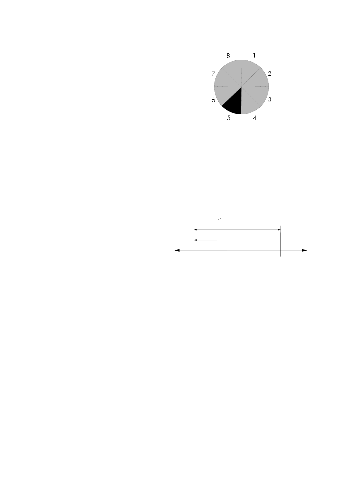
Figure 3.2: Division of the memory into 8 segments, for example
Memory space 6 to 4 is occupied.
Memory space 5 is currently being written in
Since memory spaces 6, 7 and 8 are occupied, this
example shows that the memory has been assigned
more than eight recordings. This means that No. 6 is
the oldest fault recording and No. 4 the most recent
one.
trigger occurence
recording duration
Tpre
[s]
Figure 3.3: Basic set-up of the fault recorder
Each memory segment has a specified storage time
which permits setting of a time prior to the trigger
event.
Via the interface RS485 the data can be read and
processed by means of a PC (HTL/PL-Soft4). The data
is graphically edited and displayed. Binary tracks are
recorded as well, e.g. activation and trip.
6 TD_MRN3_08.03_GB
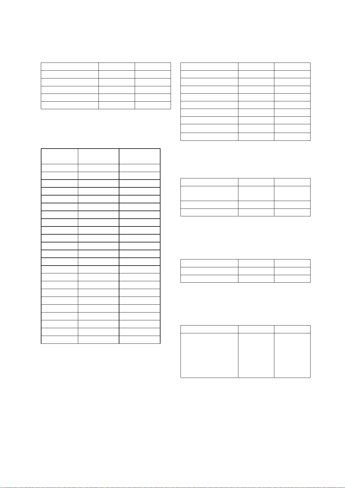
3.2 Parameter settings
23 of 87
System parameters
Parameter settings MRN3-1 MRN3-2
U
∆/Y
X X
prim/Usek
X X
fN X X
P2/FR X X
LED-Flash X X
Table 3.1: System parameters
Protection parameters
Setting
MRN3-1 MRN3-2
parameter
U< X X
tU< X X
U<< X X
t
X X
U<<
U> X X
tU> X X
U>> X X
t
X X
U>>
T X X
f1 X X
tf1 X X
f2 X X
tf2 X X
f3 X X
tf3 X X
df X
dt X
1/3 X
∆Θ
X
UB< X X
RS485/Slave X X
Baud-Rate* X X
Parity-Check* X X
Blocking functions
Parameter settings MRN3-1 MRN3-2
U< X X
U<< X X
U> X X
U>> X X
f1 X X
f2 X X
f3 X X
∆
θ
df/dt X
Table 3.3: Blocking functions
Parameters for the fault recorder
Parameter setting MRN3-1 MRN3-2
Number of fault
events
Trigger events X X
Pre-Triggerzeit T
Table 3.4: Parameters for the fault recorder
Additional functions
Parameter settings MRN3-1 MRN3-2
Ralay assignment X X
Fault recorder X X
Table 3.5: Additional functions
Date and time
Parameter settings MRN3-1 MRN3-2
Year Y = 99
Month M = 03
Table 3.2: Protection parameters
*only Modbus
Day D = 16
hour h = 07
minute m = 29
second s = 56
X
X X
X X
pre
X
X
X
X
X
X
X
X
X
X
X
X
Table 3.6: Date and time
The window for parameter setting is located behind
the measured value display. The parameter window
can be accessed via the <SELECT/RESET> key.
TD_MRN3_08.03_GB 7
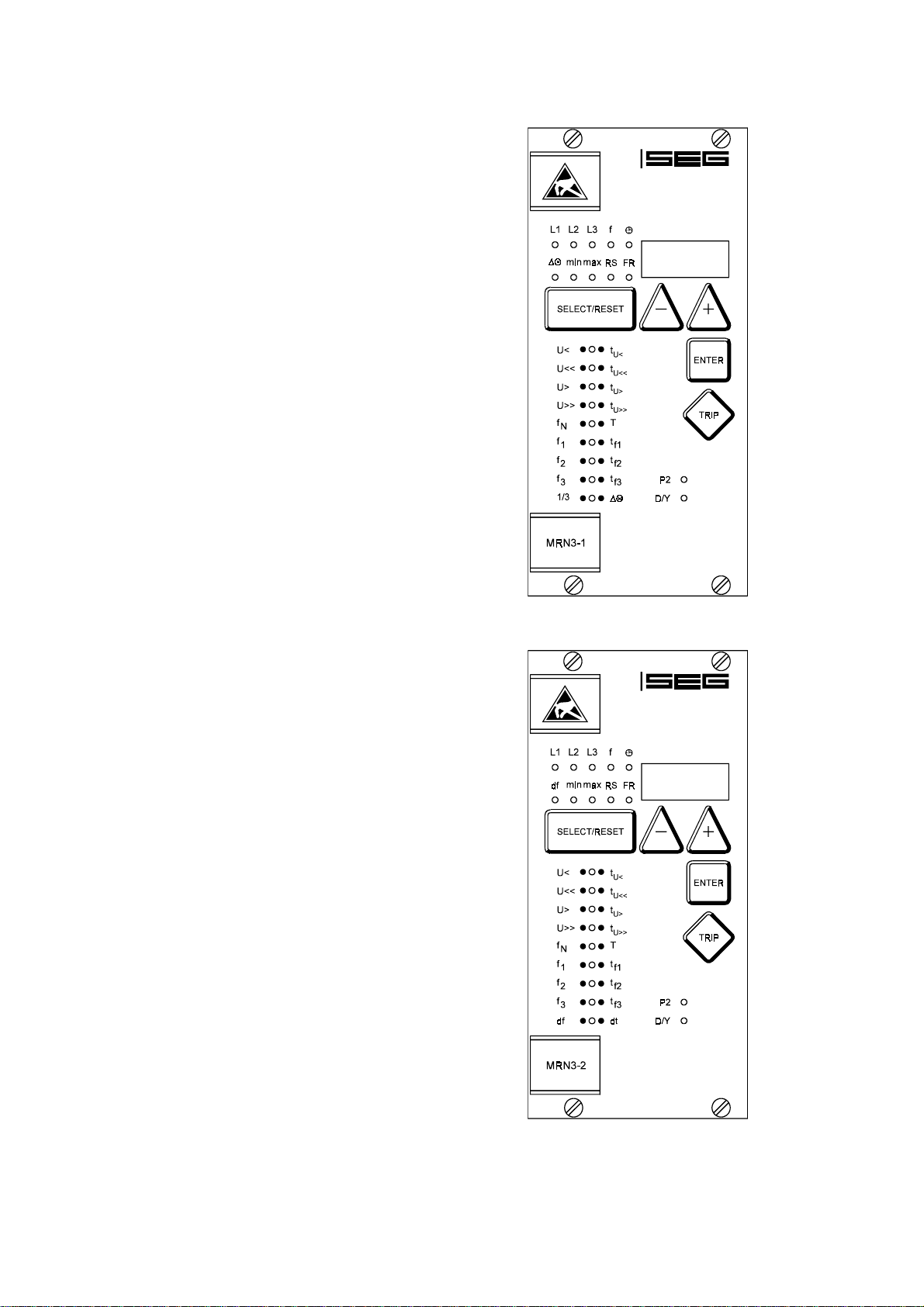
3.3 LEDs
24 of 87
All LEDs (except LED RS, min. and max.) are twocoloured. The LEDs on the left side, next to the alphanumerical display light up green during measuring and
red after tripping.
The LEDs below the push button <SELECT/RESET> are
lit green during setting and inquiry procedure of the
setting values which are printed on the left side next to
the LEDs. The LEDs will light up red after parameterizing of the setting values next to their right side.
The LED marked with letters RS lights up during setting
of the slave address of the device for serial data
communication.
The LED marked with the letters FR is alight while the
fault recorder is being adjusted.
3.4 Front plate
Figure 3.4: Front plate MRN3-1
Figure 3.5: Front plate MRN3-2
8 TD_MRN3_08.03_GB

4 Working principle
25 of 87
4.1 Analog circuits
The input voltages are galvanically insulated by the
input transformers. The noise signals caused by inductive and capacitive coupling are supressed by an analog R-C filter circuit.
The analog voltage signals are fed to the A/Dconverter of the microprocessor and transformed to
digital signals through Sample- and Hold- circuits. The
analog signals are sampled with a sampling frequency of 16 x f
ms for every measuring quantity, at 50 Hz.
4.2 Digital circuits
The essential part of the MRN3 relay is a powerful mi-
crocontroller. All of the operations, from the analog
digital conversion to the relay trip decision, are carried
out by the microcontroller digitally. The relay program
is located in an EPROM (Electrically-ProgrammableRead-Only-Memory). With this program the CPU of the
microcontroller calculates the three phase voltage in
order to detect a possible fault situation in the protected object.
For the calculation of the voltage value an efficient
digital filter based on the Fourier Transformation (DFFT
- Discrete Fast Fourier Transformation) is applied to
suppress high frequency harmonics and d.c. components caused by fault-induced transients or other system
disturbances. The microprocessor continuously compares the measured values with the preset thresholds
stored in the parameter memory (EEPROM). If a fault
occures an alarm is given and after the set tripping delay has elapsed, the corresponding trip relay is activated.
The relay setting values for all parameters are stored in
a parameter memory (EEPROM - Electrically Erasable
Programmable Read Only Memory), so that the actual
relay settings cannot be lost, even if the power supply
is interrupted.
The microprocessor is supervised by a built-in "watchdog" timer. In case of a failure the watchdog timer resets the microprocessor and gives an alarm signal via
the output relay "self supervision".
, namely, a sampling rate of 1.25
N
4.3 Voltage supervision
The voltage element of MRN3 has the application in
protection of generators, consumers and other electrical equipment against over-/and undervoltage.
The relay is equipped with a two step independent
three-phase overvoltage (U>, U>>) and undervoltage
(U<, U<<) function with completely separate time and
voltage settings.
In delta connection the phase-to-phase voltages and in
star connection the phase-to-neutral voltages are continuously compared with the preset thresholds.
For the overvoltage supervision the highest, for the undervoltage supervision of the lowest voltage of the
three phases are decisive for energizing.
TD_MRN3_08.03_GB 9
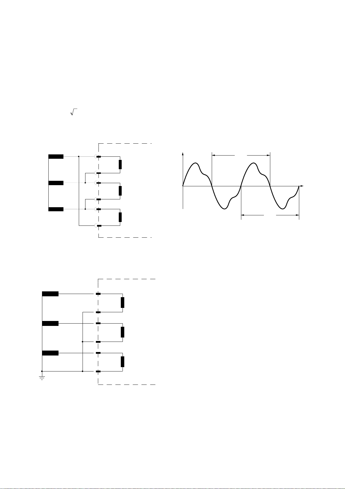
4.3.1 Selection of star or delta
26 of 87
connection
All connections of the input voltage transformers are
led to screw terminals. The nominal voltage of the device is equal to the nominal voltage of the input transformers. Dependent on the application the input transformers can be connected in either delta or star. The
connection for the phase-to-phase voltage is the delta
connection. In star connection the measuring voltage is
reduced by 1/
3
. During parameter setting the con-
nection configuration either Y or ∆ has to be adjusted.
Sec. winding of
mains V.T.
a
b
c
A3
A4
A5
A6
A7
U12
U23
4.4 Principle of frequency supervision
The frequency element of MRN3 protects electrical
generators, consumers or electrical operating equipment in general against over- or underfrequency.
The relay has independent three frequency elements
f
- f3 with a free choice of parameters, with separate
1
adjustable pickup values and delay times.
The measuring principle of the frequency supervision is
based in general on the time measurement of complete cycles, whereby a new measurement is started at
each voltage zero passage. The influence of harmonics on the measuring result is thus minimized.
u(t)
T
t
A8
Figure 4.1: Input v.t.s in delta connection (∆)
Sec. winding of
mains V.T.
a
b
c
Figure 4.2: Input v.t.s in star connection (Y)
A3
A4
A5
A6
A7
A8
U31
U1
U2
U3
T
Figure 4.3: Determination of cycle duration by means of zero
passages.
In order to avoid false tripping during occurence of interference voltages and phase shifts the relay works
with an adjustable measuring repetition. (refer to chapter 5.4.2)
Frequency tripping is sometimes not desired by low
measured voltages which for instance occur during alternator acceleration. All frequency supervision functions can be blocked with the aid of an adjustable
voltage threshold U
value is below this value.
4.5 Measuring of frequency gradient
(MRN3-2)
Electrical generators running in parallel with the mains,
e.g. industrial internal power supply plants, should be
separated from the mains when failure in the intrasystem occurs for the following reasons:
• It must be prevented that the electrical generators
are damaged when mains voltage recovering
asynchrone, e.g. after a short interruption.
• The industrial internal power supply must be main-
tained.
in case the measured voltages
B
10 TD_MRN3_08.03_GB

A reliable criterion of detecting mains failure is the
27 of 87
measurement of the rate of change of frequency df/dt.
Precondition for this is a load flow via the mains coupling point. At mains failure the load flow changing
then spontaneously leads to an increasing or decreasing frequency. At active power deficit of the internal
power station a linear drop of the frequency occurs
and a linear increase occurs at power excess. Typical
frequency gradients during application of "mains decoupling" are in the range of 0.5 Hz/s up to over 2
Hz/s. The MRN3 detects the instantaneous frequency
gradient df/dt of each mains voltage period in an interval of one half period each. Through multiple
evaluation of the frequency gradient in sequence the
continuity of the directional change (sign of the frequency gradient) is determined. Because of this special measuring procedure a high safety in tripping and
thus a high stabilty against transient processes, e.g.
switching procedure are reached. The total switching
off time at mains failure is between 60 ms and 80 ms
depending on the setting.
4.6 Vector surge supervision (MRN3-1)
The vector surge supervision protects synchronous generators in mains parallel operation due to very fast decoupling in case of mains failure. Very dangerous are
mains auto reclosings for synchronous generators. The
mains voltage returning after 300 ms can hit the
generator in asynchronous position. A very fast decoupling is also necessary in case of long time mains
failures. Generally there are two different applications:
a) Only mains parallel operation no single opera-
tion:
In this application the vector surge supervi sion protects the generator by tripping the genera- tor circuit breaker in case of mains failure.
b) Mains parallel operation and single operation:
For this application the vector surge supervision
trips the mains circuit breaker. Here it is insured
that the gen.-set is not blocked when it is required
as the emergency set.
A very fast decoupling in case of mains failures for
synchronous generators is known as very difficult. Voltage supervision units cannot be used because the synchronous alternator as well as the consumer impedance support the decreasing voltage.
For this the mains voltage drops only after some
100 ms below the pickup threshold of voltage supervision relays and therefore a safe detection of mains
auto reclosings is not possible with this kind of relay.
Frequency relays are partial unsuitable because only a
highly loaded generator decreases its speed within
100 ms. Current relays detect a fault only when shortcircuit type currents exist, but cannot avoid their development. Power relays are able to pickup within 200 ms,
but they cannot prevent power to rise to short-circuit
values too. Since power changes are also caused by
sudden loaded alternators, the use of power relays
can be problematic.
Whereas the MRN3-1 detects mains failures within
60 ms without the restrictions described above because they are specially designed for applications
where very fast decoupling from the mains is required.
Adding the operating time of a circuit breaker or contactor, the total disconnection time remains below
150 ms. Basic requirement for tripping of the generator/mains monitor is a change in load of more than
15 - 20% of the rated load. Slow changes of the system frequency, for instance at regulating processes
(adjustment of speed regulator) do not cause the relay
to trip.
Trippings can also be caused by short-circuits within
the grid, because a voltage vector surge higher than
the preset value can occur. The magnitude of the voltage vector surge depends on the distance between
the short-circuit and the generator. This function is also
of advantage to the Power Utility Company because
the mains short-circuit capacity and consequently the
energy feeding the short-circuit is limited.
To prevent a possible false tripping the vector surge
measuring can be blocked at a set low input voltage
(refer to 5.4.7). The undervoltage lockout acts faster
then the vector surge measurement.
Vector surge tripping is blocked by a phase loss so
that a VT fault (e.g. faulty VTs fuse) does not cause
false tripping.
When switching on the aux. voltage or measuring
voltage , the vector surge supervision is blocked for 5
s (refer to chapter 4.8).
TD_MRN3_08.03_GB 11
 Loading...