

Page 1
Martin Professional A/S, Olof Palmes Allé,DK-82000 Aarhus N
Phone: +45 87 40 00 00, Internet: www.martin.dk
ZR33
USER GUIDE
VERSION 1.5
MARTIN MANUFACTURING (UK) PLC
ZR33 HI-MASSZR33 HI-MASS
HI-MASS
Page 2
Note:
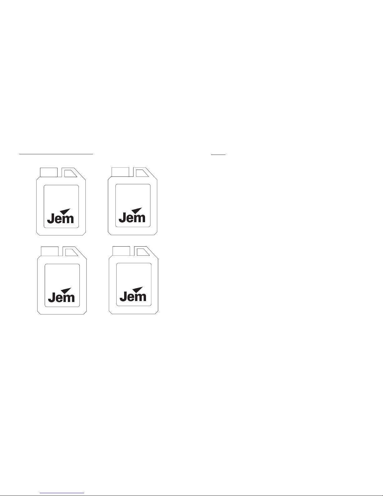
The JEM warranty will be void if any fluid other then JEM approved fluid is used. If
other fluids are used there could be serious damage to the machine and the fluid
may not of been tested for use in public areas.
MARTIN MANUFACTURING (UK) PLC
ZR33-DMX USER GUIDE
Fluids suitable for this machine:
Pro-Smoke
Super
Regular
DJ
Pro-Smoke
High Density
Pro-Smoke
Studio
ZR33-DMX USER GUIDE
MARTIN MANUFACTURING (UK) PLC
Notes:
Page 3
ZR33-DMX USER GUIDE
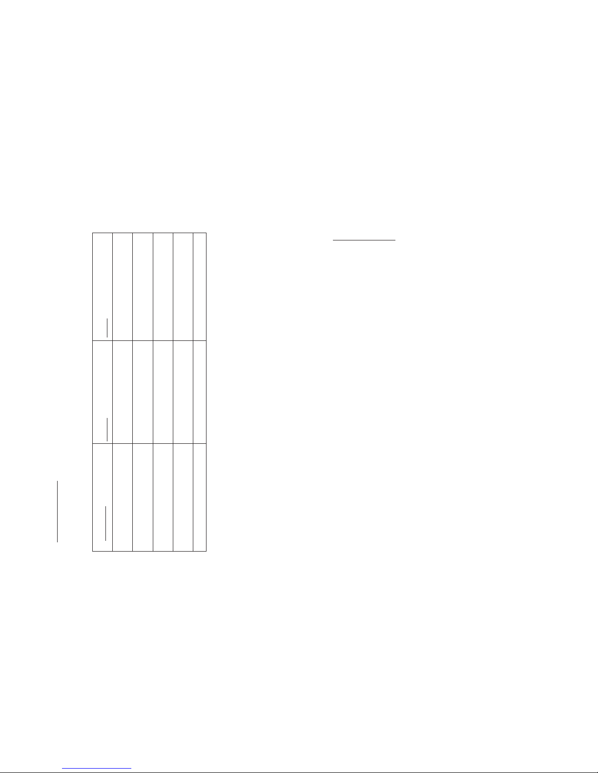
Trouble Shooting
CAUSE CURE
SYMPTOM
The mains switch does not light
when I switch on.
Main fuse blown.
No power connected.
Check main fuse.
Check power is connected.
The power LED does not light on
the remote control.
Fuse on main PCB blown.
Remote control not connected.
Check fuse on Main PCB.
Check connection of remote control.
The ready LED does not light.
even after 15 minutes.
Stand-by button is not on.
Sensor fault
Check stand-by button
Contact JEM or your Distributor.
No smoke output when fog button
is pressed (ready LED is lit).
The output knob is not set correctly
No fluid in fluid container.
Turn output knob fully clockwise.
Replace fluid container.
The effect is not lasting long enough. Fluid is the wrong grade. Choose a longer lasting fluid (SP)
PAGE 12
MARTIN MANUFACTURING (UK) PLC
ZR33-DMX USER GUIDE
•
•
•
•
•
•
•
•
•
•
•
•
User Guide Index
Introduction
Safety
Machine Layout
Getting Started
Using The Remote Control
Using DMX 512
Using The Slave Socket
The ZR33 Flying Kit
The ZR33 Ducting Kit
Trouble Shooting
How To Contact Us
PAGE 1
MARTIN MANUFACTURING (UK) PLC
Note:
Martin Manufacturing (UK) reserves the right to modify or change the
specification of this product without prior notice.
No part of this publication shall be copied without permission
© Martin Manufacturing (UK). 2000
Page 4
ZR33-DMX USER GUIDE
Introduction
The features the “HI-MASS” vaporizing system. This consists of a twin
coil system, each supplied with fluid from a high pressure oscillating piston
pump. This guarantees the maximum output from this size of vaporizing system.
Most smoke machines have one vaporizing coil and one pump, the has
two of each. JEM has also used the best possible overheat protection using our
“DTP” safety device. This was first used on the JEM with great
success and we have incorporated it on the . There is also a 9.5 (2.5
US gallons) fluid container to minimize the need to keep refilling.
To allow easy integration with a lighting control system, the comes with
DMX 512 as standard. This uses a single Channel and controls the output from a
light haze to maximum output. The also includes a well featured controller,
enabling the user to operate the machine under manual, control or via the timer
settings. The timer has a new feature called x8 mode that allows the timer values
to be multiplied by 8.
The can be installed using the flying kit supplied with the machine.
This consists of a heavy duty flying bracket, and an optional drip pad available
as an accessory. Once installed, DMX 512 can be used to control
the output.
A ducting kit is available for applications where the effect is needed in an area
away from the
HI-MASS Vaporizing System Two High Power Piston Pumps
DMX 512 As Standard Multifunction Remote Controller
“DTP” Safety System Pump Ramping For Continuous Output
9.5 Litre Fluid Capacity SMD Electronics
Low Noise Soft Start Pumping Heavy Duty Construction
Integrated Flying Bracket
ZR33
ZR33
TECHNO-FOG
ZR33
ZR33
ZR33
ZR33.
ZR33
FEATURES
Litre
or the remote
PAGE 2
MARTIN MANUFACTURING (UK) PLC
ZR33-DMX USER GUIDE
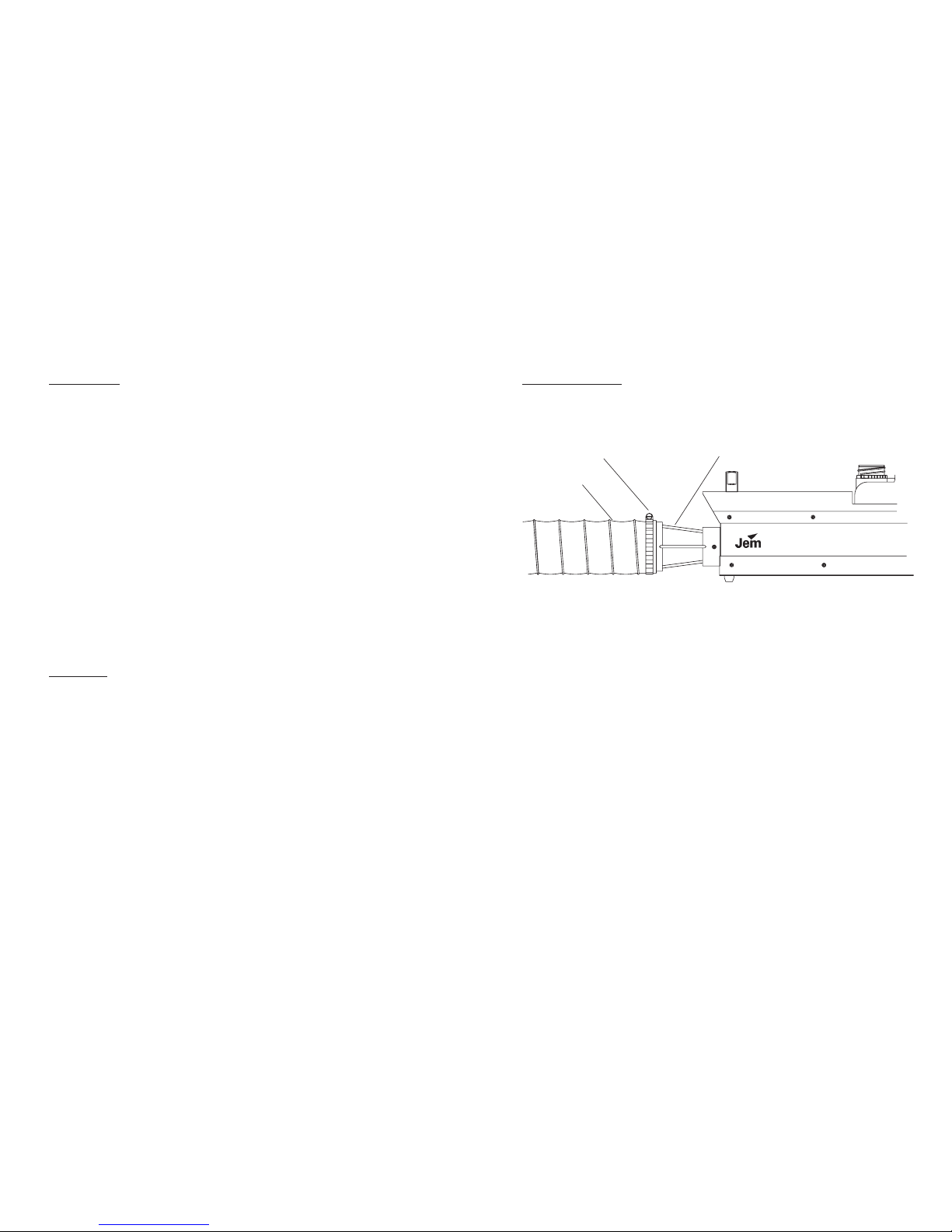
ZR33 Ducting Kit
Ducting adaptor
Jubilee clip
Ducting pipe
The JEM ZR33 ducting kit enables the user to duct the smoke from the
machine to an area where the effect is required. This is done by using the JEM
ducting adaptor and a length of 100 mm (4“) ducting pipe. The length can be
anything from a couple of metres up to 20 metres or further. There are one or
two things to beware of when using smoke machines with ducting, firstly if there
are bends to redirect the smoke they could cause condensation to form also an
air space must be provided between the output of the machine and the ducting
adaptor.
NOTE! Always use the recommended ducting adaptor and ducting
pipe, others may cause damage to the machine.
PAGE 11
MARTIN MANUFACTURING (UK) PLC
Page 5
ZR33-DMX USER GUIDE
ZR33 Flying Kit
The ZR33 flying kit enables the machine to be fixed to rigging and ceilings for use
where the ZR33 is best situated in a flying position. The kit is supplied as standard with
the option of a drip pad for catching unwanted drips that can occur when smoke
machines are angled down.
NOTE! Always follow instructions when installing smoke machines. A safety
strap must be fixed from the rigging to the handle to ensure maximum safety..
PAGE 10
MARTIN MANUFACTURING (UK) PLC
ZR33 HI-MASSZR33 HI-MASS
Hanging Bracket
Safety Strap
ZR33-DMX USER GUIDE
Safety
•
•
•
•
•
•
•
•
•
•
Always use a JEM approved fluid, other fluids could be dangerous and could
cause damage to the machine.
Always check the voltage is correct for use with the machine, the voltage
setting is printed on the serial label.
Always read the user guide before operating the machine, smoke machines
need to be operated carefully to avoid risk.
Never touch the nozzle at the front of the machine, the nozzle can stay hot for
up to 10 hours.
Do not remove the cover or attempt to repair a faulty machine, an authorized
JEM dealer should be contacted in the event of a faulty machine.
Always use smoke machines in well ventilated areas, over use could affect
sufferers of asthma or other chest conditions.
Do not use the machine if there is a faulty mains lead or plug this could be
dangerous.
Never point the output directly at peoples heads, this is a high powered
smoke machine.
Always use approved accessories with this machine.
Do not spill fluid over the machine, if fluid is spilt clean with clean water and
contact an approved JEM dealer for advice.
Mains Lead Wiring Instructions
Brown = Live
Blue = Neutral
Green/Yelllow = Earth
Note! This Appliance must be earthed
PAGE 3
MARTIN MANUFACTURING (UK) PLC
Page 6

ZR33-DMX USER GUIDE
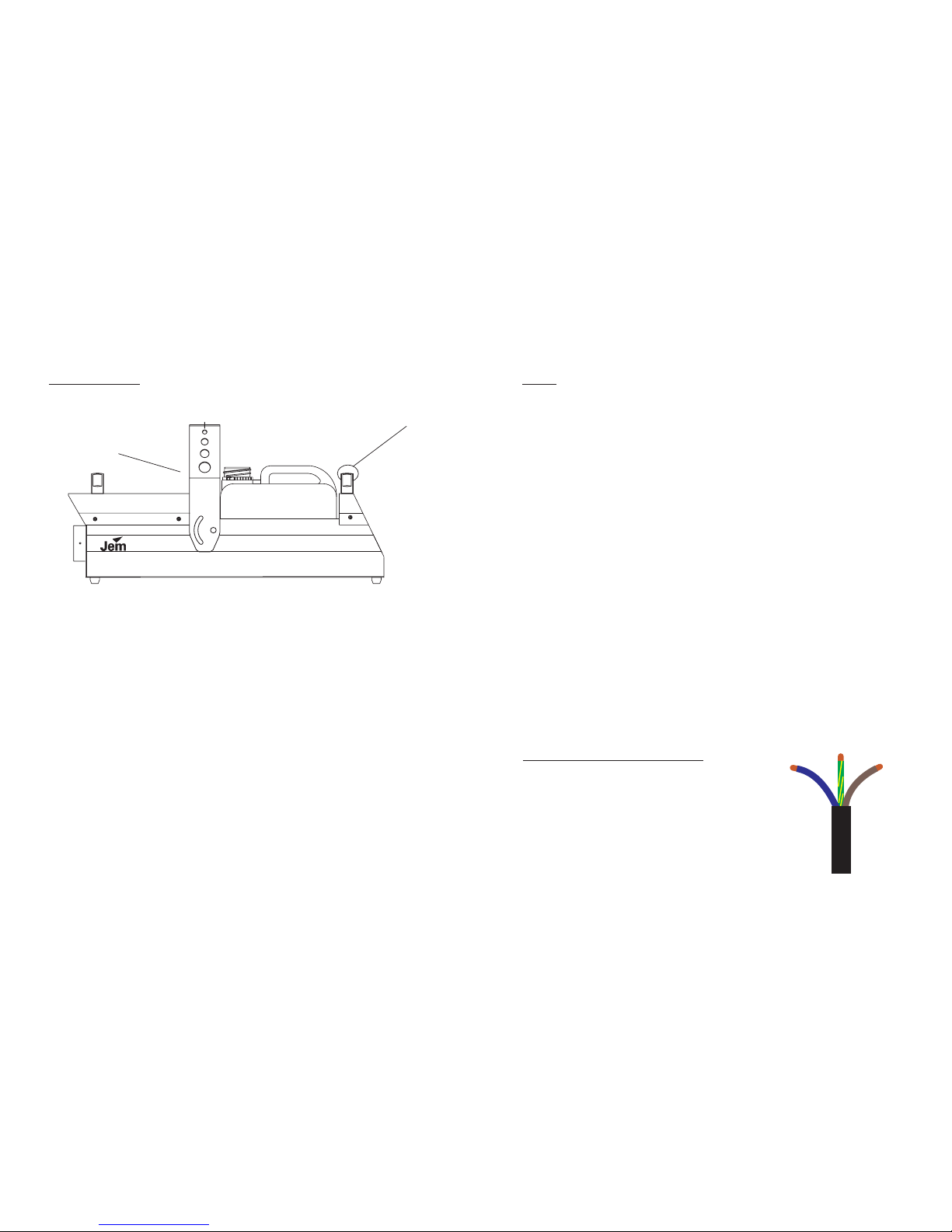
Machine Layout
12345678910123 4 5 6 7 8 9 10
ON
PUSH
DMX XLR (out)
DMX XLR (in)
DMX address switches
Slave socket
Ready LED
Mains switch
Main fuse
leadMains
Remote control
WARNING
Output nozzle
Fluid container
sefsgsfhdthehd dggdg redrhryj
thrhrhrhtrthrthrthrthrhhw rhrtrt
rhrtjrjrrjhrj rjtr rjrjryjr;’l’oherw
torhrth;hj;d;o oekh;r ;kh;do
okldh;d;ld rep epe’kdh;dh;dj;
oi;osuvistliv; ulgiss;svsuito;svn;
ithisvns;iosi norit;si;soiv;svns;o
s[os’‘spov’peo’‘ov sneorvn’svns’
psivpsoeveerepeo eporpeop ete
eioeov eoiov erereteteeteteer yeh
egprogpp irphgido I [eigpe [i[p
eooeihoeeih[ehi[p eihoeih[hoi[e
PAGE 4
MARTIN MANUFACTURING (UK) PLC
A Martin Professional product
ZR33
High Performance
Fog Generator
HIGH TEMPERATURE
VAPOUR
AND SURFACES
ON
TIMER
ON
1
1
1
2
2
2
3
3
3
4
4
4
5
5
5
6
6
6
7
7
7
8
8
8
9
9
9
POWERPOWER
CYCLE
MULTI-FUNCTION
CONTROLLER
MULTI-FUNCTION
CONTROLLER
OUTPUT
DELAY
RUN
FOG
x8
STAND-BY
ON
ZR33-DMX USER GUIDE
Using The Slave Socket
The has the ability to connect machines together using a XLR lead and
then operating all of the machines with one controller. This is ideal when there
is a need for lots of smoke and there is no DMX to operate the machines.
Simply remove the controllers from all but one of the machines and then connect
an XLR lead (3 pin) from the slave socket of the first machine (the one with the
controller) to the next machine’s remote socket, and then from that machine’s
slave to the next machine’s remote socket. This can be done from two up to ten
machines maximum. All of the machines will operate with the same output and
timer settings as the first machine.
ZR33
Pin 1 - GND
Pin 2 - NA
Pin 3 - 0 -10V signal
Wiring of XLR
Slave socket
Remote socket
To next machine
First machine
PAGE 9
MARTIN MANUFACTURING (UK) PLC
12345678910123 4 5 6 7 8 9 10
ON
PUSH
sefsgsfhdthehd dggdg redrhryj
thrhrhrhtrthrthrthrthrhhw rhrtrt
rhrtjrjrrjhrj rjtr rjrjryjr;’l’oherw
torhrth;hj;d;o oekh;r ;kh;do
okldh;d;ld rep epe’kdh;dh;dj;
oi;osuvistliv; ulgiss;svsuito;svn;
ithisvns;iosi norit;si;soiv;svns;o
s[os’‘spov’peo’‘ov sneorvn’svns’
psivpsoeveerepeo eporpeop ete
eioeov eoiov erereteteeteteer yeh
egprogpp irphgido I [eigpe [i[p
eooeihoeeih[ehi[p eihoeih[hoi[e
ZR33
High Performance
Fog Generator
ZR33
High Performance
Fog Generator
A Martin Professional product
A Martin Professional product
ON
TIMER
ON
1
1
1
2
2
2
3
3
3
4
4
4
5
5
5
6
6
6
7
7
7
8
8
8
9
9
9
POWER
CYCLE
MULTI-FUNCTION
CONTROLLER
MULTI-FUNCTION
CONTROLLER
OUTPUT
DELAY
RUN
FOG
x8
STAND-BY
ON
Page 7
ZR33-DMX USER GUIDE
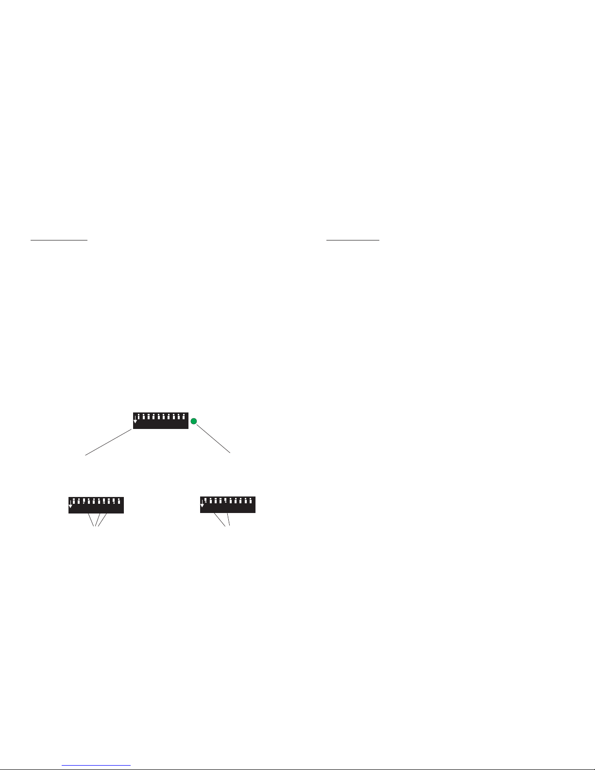
Using DMX 512
Within the lighting industry, the DMX communication protocol is widely used for
remote control of lighting and other equipment. The is fitted with a DMX 512
compliant interface as standard, giving the user the possibility of controlling the smoke
and light from a single source. The uses a single channel to fire and control the
output level; the interface can be addressed from channel 1 to channel 512. The
address is set using the 10 way dip switch at the rear of the machine. To address the
channel, convert the channel number to binary and set this number on the switches (on
is down). There are some samples of different channel settings below.
The is fitted with two XLR sockets, one is for DMX IN & one is for DMX
OUT, enabling the to be used in a chain. When there is valid DMX, i.e. the XLR
is connected and the desk is powered, the small green LED will light. However, if there
is no address set, the LED will not light and DMX will be disabled. If an address is set
and DMX is present the machine will automatically start to heat up and after 10 - 12
minutes you will be able to operate the machine using DMX. Increasing the DMX level
will increase the smoke output level.
ZR33
ZR33
ZR33
ZR33
12345678910
101099887766554433221
1
ON
ON
ON
Valid DMX LED
Address Switches
512
512
256
256
128
128
64
64
32
32
16
16
8844221
1
DMX Value
Switches 3,7, &9 on
Address set to 324
Switches1&5on
Address set to 17
PAGE 8
MARTIN MANUFACTURING (UK) PLC
ZR33-DMX USER GUIDE
Getting Started
•
•
•
•
Once you have selected the best position for the you can begin to use
the machine. Check that the mains power supply matches the voltage and
frequency on the serial number label. If not, contact your JEM dealer for
advice.
Now set the mains switch, at the rear of the machine, to the ‘ON’ position
and press the grey “stand-by” button.
Allow around 10 -12 minutes for the machine to reach operating temperature
While it heats up you should check the level in the fluid container, the
container can hold up to 9.5 litres of fluid.
NOTE! Do not allow the to run out of fluid. Serious damage may
occur if the machine is operated when no fluid is connected.
When the machine has reached working temperature the green “ready” LED
will light on the rear of the machine and the machine can now be operated.
Check the “output” knob is turned fully clockwise (maximum) then press and
hold the red “fog” button. The fluid pumps will start operating; if the
machine has a new container of fluid it will take a few seconds for the pumps
to prime.
When the pump has primed smoke will be visible. The output can now be set
to the desired level by turning the “output” knob. The timer may be activated
or you can simply use the “fog” button when smoke is required, Alternately
you may wish to use DMX to operate the .
For further information on using the controller and DMX see the relevant
pages in this user guide.
When you have finished using the machine you should use the “stand-by”
button to turn off the heaters and then turn the mains switch off. If any
problems occur when operating the please refer to the trouble
shooting guide..
ZR33
ZR33
ZR33
ZR33
PAGE 5
MARTIN MANUFACTURING (UK) PLC
Page 8
ZR33-DMX USER GUIDE
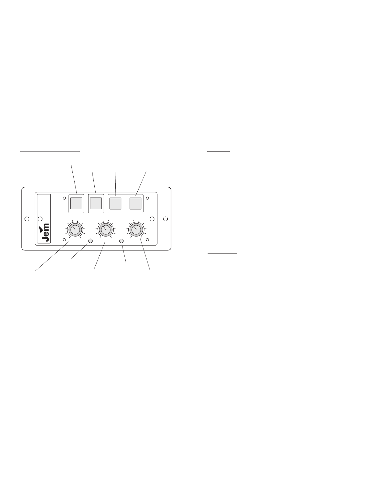
Using The Remote Control
Fog Button
Stand-by Button
Timer Value Button
Timer Engage Button
Output Control
Power LED
Delay Time Control
Timer Cycle LED
Run Time Control
The comes with a comprehensive controller that allows the user to
manually fire the machine, or set a well featured timer to operate the
machine automatically. When the “ready” LED is lit at the rear of the
machine the remote becomes functional and the “fog” button will operate
the machine when pressed. Sometimes a pre-determined amount of smoke is
needed and the remote has a timer that will operate over a wide
range or varying times. The x8 timer value gives even greater flexibility
when a longer delay and run time are needed.
ZR33
ZR33
PAGE 6
MARTIN MANUFACTURING (UK) PLC
ON
TIMER
ON
1
1
1
2
2
2
3
3
3
4
4
4
5
5
5
6
6
6
7
7
7
8
8
8
9
9
9
POWER
CYCLE
MULTI-FUNCTION
CONTROLLER
OUTPUT
DELAY
RUN
FOG
x8
STAND-BY
ON
ZR33-DMX USER GUIDE
Functions
FOG BUTTON: Will when the machine has reached operating temperature fire
the machine when pressed and held.
STAND-BY BUTTON: This turns the machines electronics on and off.
TIMER VALUE BUTTON: When the timer is being used, the timer values can be
adjusted by a factor of 8, i.e. a 5 second minimum run time becomes 40 seconds &
a 10 second delay time becomes 1 minute 20 seconds.
TIMER ENGAGE: This will engage the timer to fire the machine according to the
present settings.
OUTPUT CONTROL: Turning this knob clockwise will increase the output of the
machine, if turned fully anti-clockwise there will be no output.
DELAY TIME CONTROL: This will adjust the amount of time the machine waits
between operating when the timer is engaged.
RUN TIME CONTROL: This will adjust the time the machine will operate for
when the timer is engaged.
POWER LED: This LED will light when the machine is switched on
CYCLE LED: This LED will light when the timer is engaged and the machine is
operating.
Timer Values
Maximum = 18 seconds
Minimum = 2 seconds
Run Time: X1 mode
Maximum = 2 minutes 24 seconds
Minimum = 16 seconds
Run Time: X8 mode
Maximum = 18 seconds
Minimum = 2 seconds
Delay Time: X1 mode
Maximum = 2 minutes 24 seconds
Minimum = 16 seconds
Delay Time: X8 mode
An extension lead is available from JEM for using the controller out of
the machine.
PAGE 7
MARTIN MANUFACTURING (UK) PLC
 Loading...