

Page 1
IMPORTANT INFORMATION AND GLOSSARY
INSTALLATION INSTRUCTIONS
for Fiberglass Gliding Patio Doors with Applied Nailing Fin (JII104)
Thank you for selecting JELD-WEN products. Attached are
JELD-WEN's recommended installation instructions for berglass
gliding patio doors with applied nailing n. Read these instructions
thoroughly before beginning. They are designed to work in most
existing applications, however; existing conditions may require
changes to these instructions. If changes are needed, they are made
at the installer's risk. For installations other than indicated in these
instructions, contact a building professional.
Newer construction methods have led to an increase in air and water
tightness in buildings. This frequently leads to negative air pressure
inside the home, which can draw water through very small openings.
Our installation method seals the patio door to the weather barrier
(typically building wrap) and uses a sill pan to capture and drain
incidental storm water from under the patio door.
Consult your local building code ofcial for applicable building
codes and regulations. Local building code requirements supersede
recommended installation instructions.
Please Note! Any patio door installation where the sill is higher than
35 feet above ground level or into a wall condition not specically
addressed in these instructions must be designed by an architect or
structural engineer. Failure to install square, level and plumb and on a
at surface (without twist or warp) could result in denial of warranty
claims for operational or performance problems.
Note to Installer: Provide a copy of these instructions to the building
owner. By installing this product, you acknowledge the terms and
conditions of the limited warranty as part of the terms of the sale.
GLOSSARY
Applied Nailing Fin
A piece of vinyl or aluminum that is slid into a track in the outside of a
window or patio door frame.
Backer Rod (backing material)
A material (e.g. foam rod), placed into a joint primarily to control the
depth of the sealant.
Buck
A wood framework attached to the masonry inside a window or patio
door rough opening.
Pilot Hole
A drilled hole that is no larger than the body of the screw (minus the
threads).
Shiplap
The layering method in which each layer overlaps the layer below it so
that water runs down the outside.
Weep Hole (weep channel)
The visible exit or entry part of a water drainage system used to drain
water out of a door.
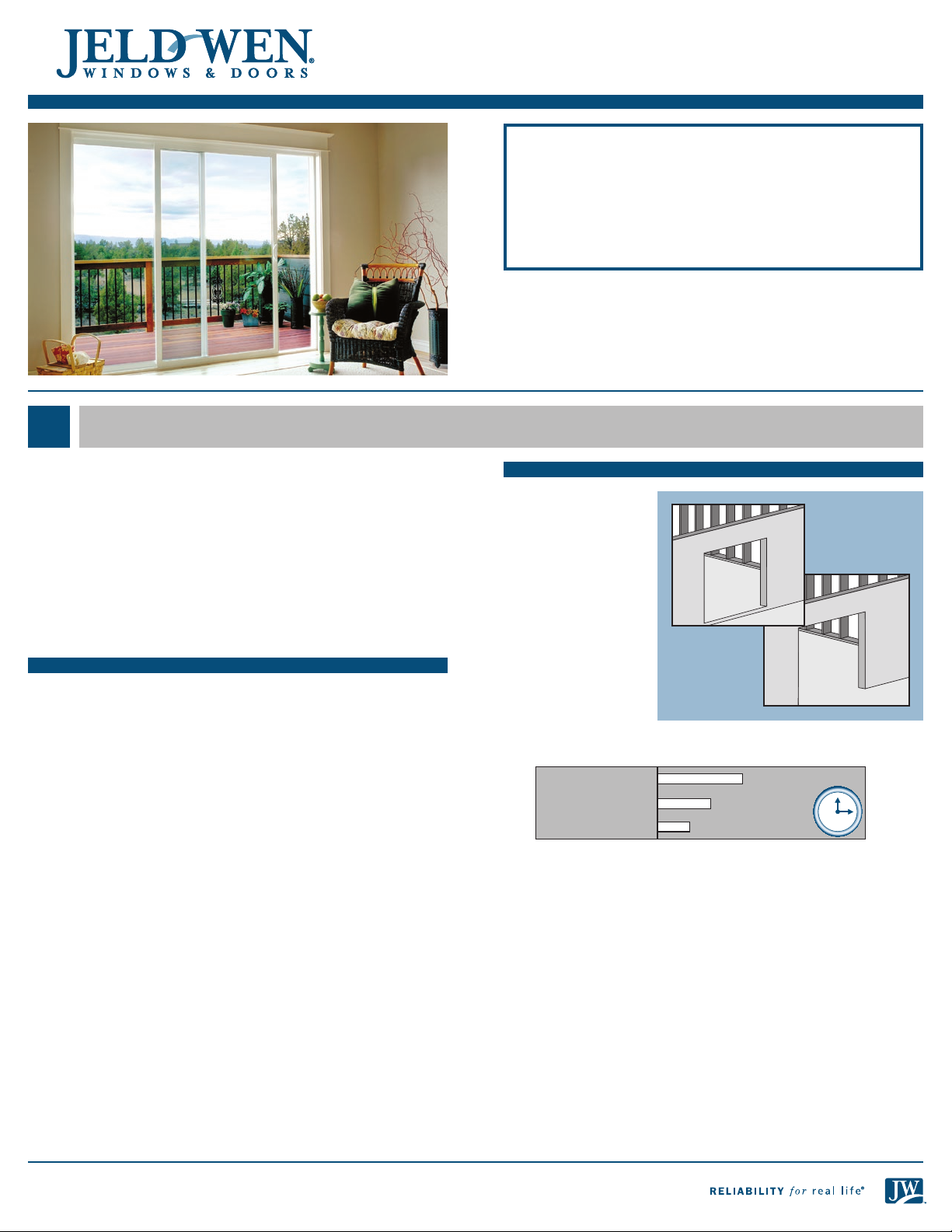
LANDINGS
These instructions
cover two patio door
sill conditions: the
step-down landing
and the continuous
slab landing. The
installation methods
vary slightly between
landing types.
Estimated Install
Time for New
Construction
Continuous
Slab Landing
Experienced: 1.25 hr.
Professional: 0.75 hr.
Step-Down
Landing
First Time: 1.75 hr.
12
11
10
9
8 4
7 5
6
1
2
3
Page 2
ROUGH OPENINGS
INSTALLATION INSTRUCTIONS
for Fiberglass Gliding Patio Doors with Applied Nailing Fin (JII104)
This installation guide specically addresses masonry/block wall,
sheathed wall and open-stud construction.
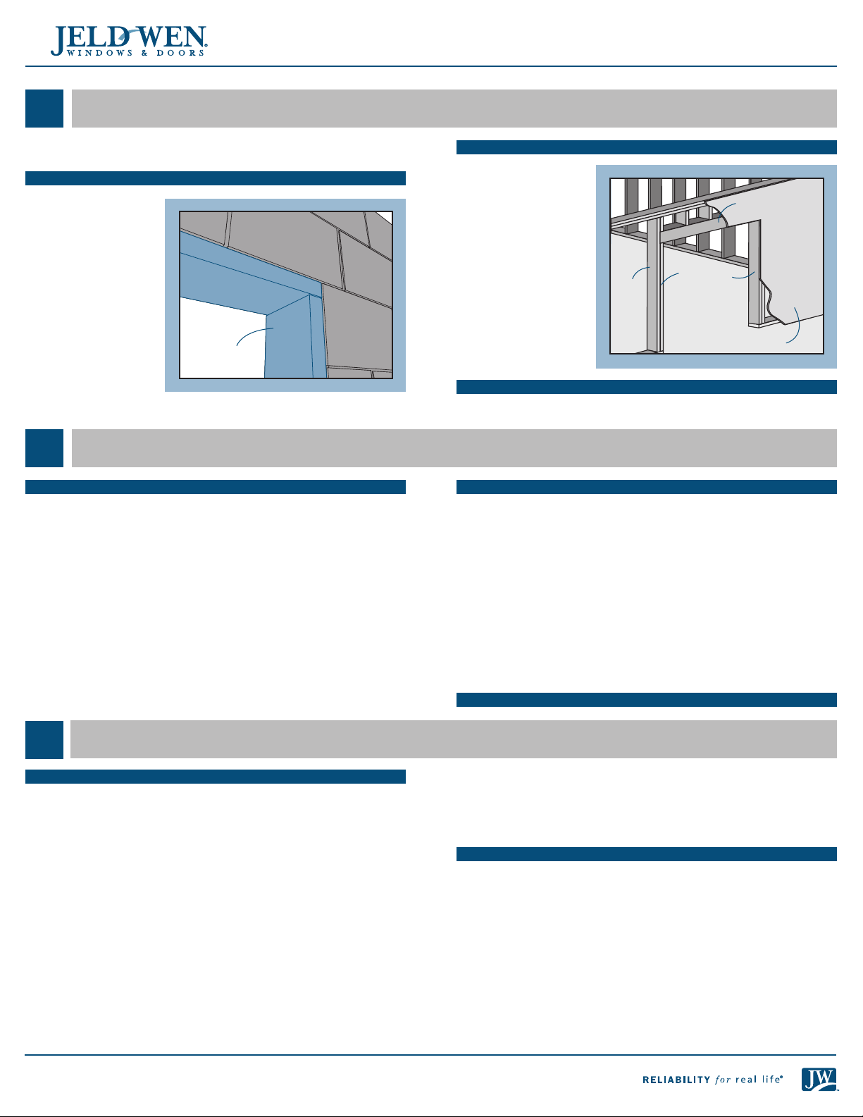
MASONRY/BLOCK WALL CONSTRUCTION
This installation
assumes that a
framework of 2x studs
(often called a buck)
has already been
properly fastened and
sealed to the concrete/
masonry wall by a
building professional.
Buck
SAFETY AND HANDLING
SAFETY
• Read and fully understand ALL manufacturers’ instructions before
beginning.
• Do not work alone. Two or more people are required. Use safe lifting
techniques.
• Use caution when handling glass. Broken or cracked glass can cause
serious injury.
• Wear protective gear (e.g. safety glasses, gloves, ear protection, etc.).
• Operate hand/power tools safely and follow manufacturer’s operating
instructions.
• Use caution when working at elevated heights.
FULLY SHEATHED WALL CONSTRUC TION
The wall framing is
covered by sheathing.
This installation
assumes building wrap
is properly installed
prior to installation.
Trimmer
King
stud
OPEN-STUD CONSTRUCTION
Wall framing is not covered by sheathing.
MATERIALS & PATIO DOOR HANDLING
• Make sure the operating panel is secured prior to installation.
• Heed material manufacturers’ handling and application instructions.
• Protect adhesive surfaces from dirt, moisture, direct sunlight and
folding over onto themselves.
• Handle in vertical position; do not drag on oor.
• Do not put stress on joints, corners or frames.
• Store patio door in dry, well-ventilated area in vertical, leaning
position to allow air circulation; do not stack horizontally.
• Protect from exposure to direct sunlight during storage.
• Install only into vertical walls and when conditions and sheathing
are dry.
• Never use solvent-based sealants on vinyl products.
IF INJURY OCCURS, IMMEDIATELY SEEK MEDICAL ATTENTION!
studs
Sill area
Header
Sheathing
NEEDED MATERIALS AND TOOLS
MATERIALS
• #8 x 1" truss head corrosion-resistant screws. Do not use drywall
screws.
• 3/16" x 2 1/2" self-tapping concrete screws (if securing into concrete/
masonry)
• Non compressible or water degradable shims
• 4", 6", or 9" (as required by local code and window conguration)
wide self-adhesive ashing: We recommend OSI® QUAD® Butyl
Flashing Tape or equivalent.
• Spray adhesive/primer for self adhesive ashing. Such as Loctite® 300
or equivalent
• Sealant: We recommend OSI® QUAD® Max Sealant or equivalent. This
can be used in any application and can be painted or ordered in a
color matched product, if desired.
• Backer rod 1/8" larger than the widest portion of the gap (used in
conjunction with sealant bead).
• Plastic drain screen with crisscross or woven pattern (sold in 6" widths
to protect rain gutters) for step-down landings
2
• Sheet metal ashing or bendable vinyl sheeting for sill pan (6" wide
for 2" x 4" wall, 9" for a 2" x 6" wall)
• 3/8" staples for step-down landings
Note! Follow all material manufacturers’ instructions for proper use
and compatibility.
TOOLS
• Cutting shears (sill pan)
• Tape measure
• Utility knife
• Level (4' minimum
recommended)
• J-roller
• Caulking gun
• Drill
• Construction stapler
• Clean rags
• Phillips screwdriver
Page 3
INSTALLATION INSTRUCTIONS
for Fiberglass Gliding Patio Doors with Applied Nailing Fin (JII104)
1
REMOVE PACKAGING
Remove shipping materials such as corner covers, shipping blocks or
pads. Remove any temporary handles just prior to installation into the
rough opening.
INSPECT PATIO DOOR
• Cosmetic damage
• Product squareness (diagonal measurements must be within 1/4"
difference)
2
• Verify the width and
height of the patio
door are each
1/2"- 3/4" smaller
than the rough
opening width/
height. Mulled
units should be 3/4"
smaller.
• Verify the rough
opening is square.
The (A) and (B)
measurements
should be the same.
Maximum allowable
deviation from square
is 1/4".
REMOVE PACKAGING AND INSPECT PATIO DOOR
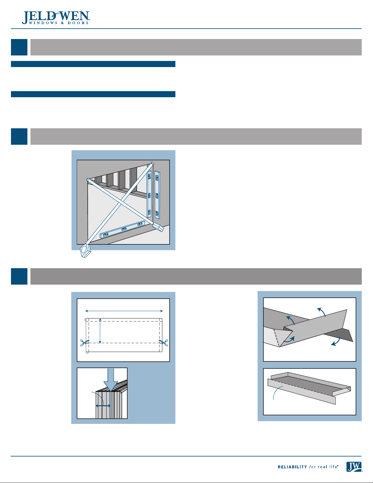
INSPECT ROUGH OPENING
Verify Square, Level, & Plumb
A
C
B
D
E
• Correct product (size, color, grid pattern, handing, glazing, energyefciency requirements, etc.)
• For side-by-side mulled units, a drip cap that extends the length of the
frame plus 1/8" overhang on each end is required.
If any of the above conditions represent a concern, or if you expect
environmental conditions to exceed the patio door's performance
rating, do not install the patio door. Contact your dealer or distributor
for recommendations.
• Verify the rough opening is level and plumb (C) and (D). The
maximum allowable deviation is 1/8".
• The rough opening sill must not be crowned or sagged (D). A 5 degree
sloped sill is recommended.
• The exterior face of the rough opening must be in a single plane (E)
with less than 1/8" twist from corner to corner.
• Minimum double studs should be used at all wood framed rough
openings.
• The header must be supported by trimmer studs.
3
1. Cut a piece of sheet
material to the
length shown.
2. Lightly crease folding
lines 1/2" in from the
two short sides and
one long side.
3. Measure the width of
the frame from the
interior to the nailing
n slot and add
9/16".
4. Take this distance
from the back edge
and lightly crease a
folding line across
the sheet material.
5. For step-down
landings, cut 1/2" in
at the folding line
on both sides of the
sheet material.
6. For continuous slab,
cut across the folding line.
PREPARE SILL PAN
Length of rough opening sill plus 1"
1/2"
1/2"
Measure
frame
width
Interior
Frame width
+9/16"
Folding line
Jamb n
slot
7. Fold the three back
sides up to make a
3-sided box, and, for
step-down landings,
fold the front ap
down.
Fold sides and back up
Fold corner
forward
For continuous
slab, remove ap
Fold front
ap down
3
Page 4
INSTALLATION INSTRUCTIONS
S
p
r
a
y
A
d
h
e
s
i
v
e
for Fiberglass Gliding Patio Doors with Applied Nailing Fin (JII104)
4
PREPARE STUD-FRAMED WALL
Note! This section covers stud-framed wall instructions. Masonry/buck
instructions begin after with “PREPARE BUCK.”
FOR RETROFIT INSTALLATIONS
Remove the old patio door. If installing into stud framing, remove
sufcient siding to expose at least 9" of intact building wrap. If
damaged, apply new building wrap in a shiplap manner. Verify header
and trimmer studs are structurally sound. If installing into a block wall,
removing the stucco is not necessary if the existing rough opening
is waterproof and the patio door is downsized. Continue with the
instructions.
PREPARE BUILDING WRAP
Cut ush with the
edges of the rough
opening, or follow
building wrap
manufacturer’s
instructions for proper
methods of preparing
the weather barrier.
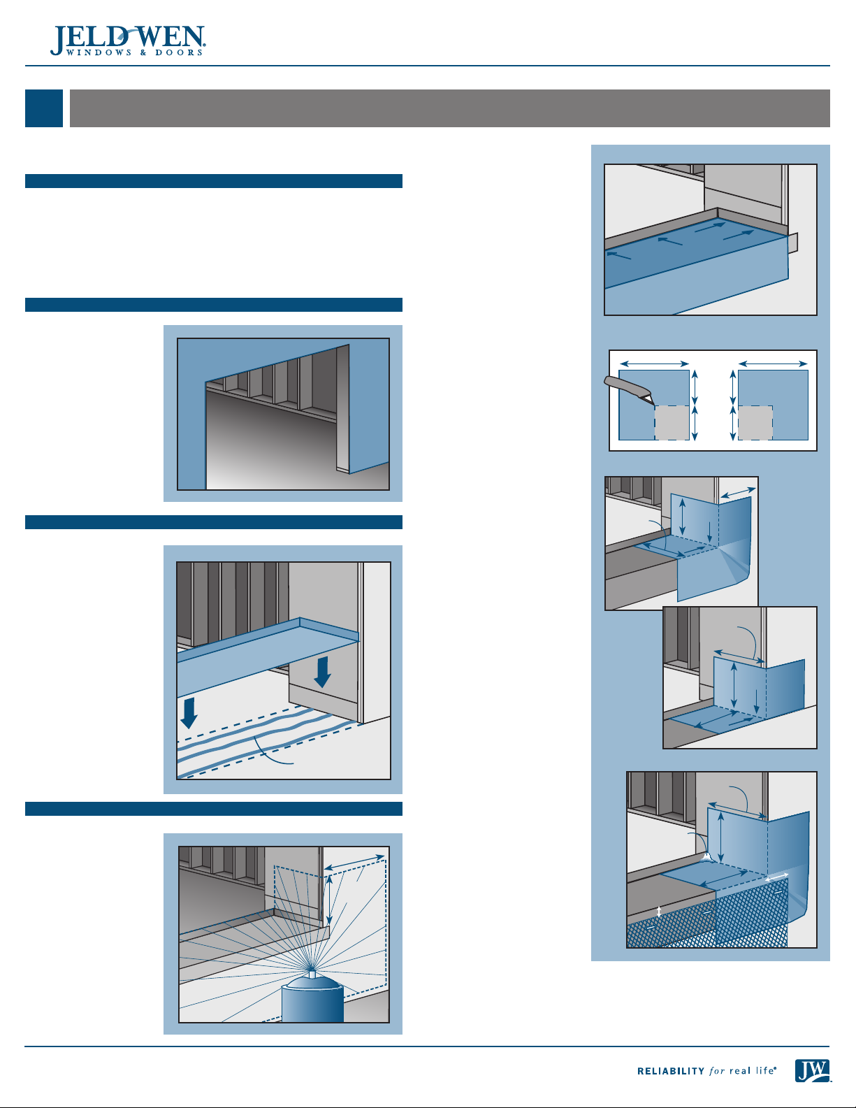
PREPARE SILL
1. Set the sill pan in
the rough opening,
aligning the front
edge (for continuous
slab, shown) or
folded down edge
(for step down) with
the exterior of the
rough opening.
2. Mark a line across
the front and back
of the sill pan and
remove.
3. Apply three 3/8"
beads of sealant
between the marked
Sealant
lines.
INSTALL SILL PAN
4. Place the sill pan in
the rough opening.
Firmly press the sill
6"
pan in place with a
J-roller.
5. Apply spray adhesive/
3"
primer to the sill pan
and surrounding
area. Follow
manufacturer’s
instructions for
application methods.
6. Cut a piece of selfadhesive ashing
the length of the sill
and apply over the
sill pan as shown.
The bottom of the
sill pan should be
completely covered
by the self-adhesive
ashing. For step
down landings,
fold ashing down
as shown. For
continuous slabs,
trim ush with
rough opening.
7. Cut two pieces
of self-adhesive
ashing 6" wide by
the sill pan width +
3" long.
a. For continuous
slab landings
only, cut out
the inside
corner.
b. Adhere the
pieces of
ashing to the
inside corners.
Stretch ashing
as needed to
cover corners
and lay at.
8. Smooth gaps or
bubbles beneath
self-adhesive
ashing with a
J-roller (remove
and replace if
necessary).
9. Seal back corners
of sill pan with
sealant.
10. For step-down
landings only, cut
plastic drain screen
to length of sill
+ 2" and staple
1/2" below sill
edge. The drain
screen provides
a path for air to
dry any incidental
moisture in the
rough opening.
Self-Sealing Corner Flash
6"
Discard
(for
continuous
slab only)
Step-Down Landing
Sill pan
width
Continuous
Slab
Landing
3"
3"
Sealant
1/2"
Sill
pan
width
3"
Sill pan
width
3"
Sill pan
width
3"
3"
3"
3"
Discard
(for
continuous
slab only)
3"
6"
1"
4
Page 5

INSTALLATION INSTRUCTIONS
for Fiberglass Gliding Patio Doors with Applied Nailing Fin (JII104)
5
PREPARE BUCK
PREPARE BUCK (MASONRY/BLOCK WALL ONLY)
1. On the exterior, coat the buck and surrounding concrete/masonry
with self-adhesive ashing primer. Follow manufacturer’s instructions
for application procedures.
2. Seal the joint between the buck and the concrete/masonry with
self-adhesive ashing as follows:
Note! Do not allow gaps or bubbles beneath the ashing (remove and
replace if necessary).
a. Cut ve pieces
of self-adhesive
ashing for the
sill, sides, head,
Head/Sill piece
1.5"
3"
and sill pan as
shown.
Rough opening head/sill +3"
Side piece
Side piece
Rough opening side jamb +3"
= Remove for step down only
1.5"
3"
Top
b. Apply the sill
piece as shown.
d. Apply the sill
pan piece of
self-adhesive
ashing over
the sill pan as
shown. The
bottom of the
sill pan should
be sealed by the
ashing.
e. Remove the
upper end
corner of each
side piece, and
for step-down
landings,
remove the
lower end
corner.
f. Apply the
side pieces of
self-adhesive
ashing.
g. Remove the
corners of the
header piece
and apply.
3. Apply sealant across
ashing/masonry
joints at corners of
masonry opening.
Sealant
c. Place the sill pan
in the rough
opening.
4. Apply diamond lath
to all ashed surfaces
to be covered by
stucco.
5
Page 6
INSTALLATION INSTRUCTIONS
for Fiberglass Gliding Patio Doors with Applied Nailing Fin (JII104)
6
INSTALL PATIO DOOR
Warning! To avoid
injury, use at least
two people to install.
Adequately support
the door until fully
installed.
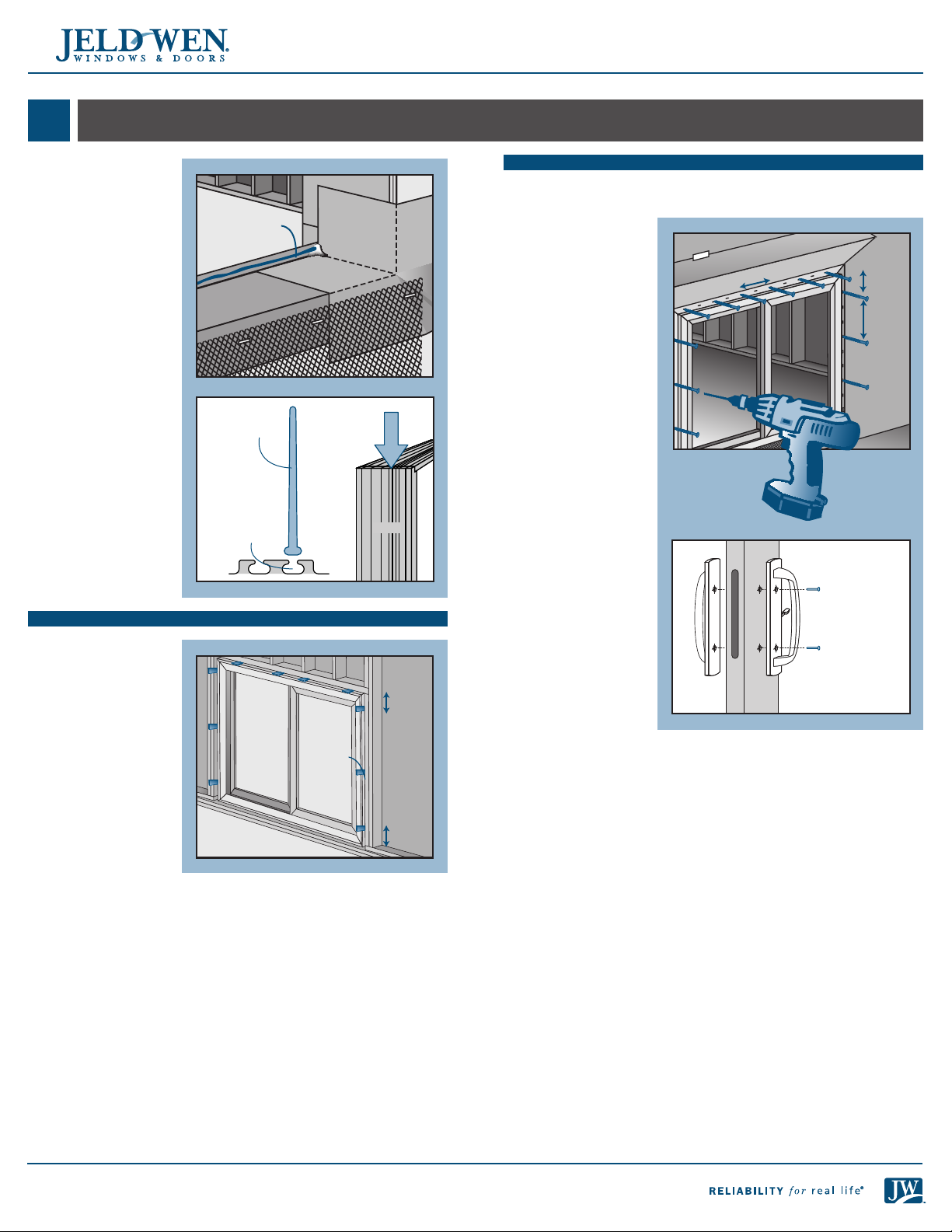
1. Apply a 3/8"
continuous bead of
sealant across the sill
pan back dam.
2. Install nailing ns
into the appropriate
jamb n slots on
the side jambs and
the head jamb.
NOTE: Be careful to
apply the nailing n
intersection gaskets
at the top corners
(one in each side
jamb and one in the
head jamb).
3. Tilt patio door into
the rough opening.
Make sure the back
of the door makes
solid contact with the
sealant.
SHIM THE JAMBS
Note! Secure all shims
with sealant.
4. From the interior,
shim the side jambs
6" from the corners
and then at the
center point. Shim
the head 6" from the
corners and then at
8" intervals. Shim so
the door is square,
level and plumb.
5. Temporarily secure
both top corners
through the nailing
n until door is fully
installed.
6. Verify the door is
square, level and plumb.
Sealant
Fin
Jamb n slot
Interior
Jamb n
slot
Interior
8"
Strike
plate
Jamb
6"
6"
SECURE PATIO DOOR
Note! Do not over tighten fasteners and do not allow fasteners to
deform the nailing n, it must be kept at and straight.
7. At each remaining
corner and at 5"
intervals, fasten
patio door through
the nailing n with
4"
4"
#8 x 1" washer or
pan head screws.
For step-down
5"
landings, secure
the sill in the same
manner.
8. Install handle on
the operating panel
with the provided
screws.
Interior
6
Page 7
INSTALLATION INSTRUCTIONS
for Fiberglass Gliding Patio Doors with Applied Nailing Fin (JII104)
7
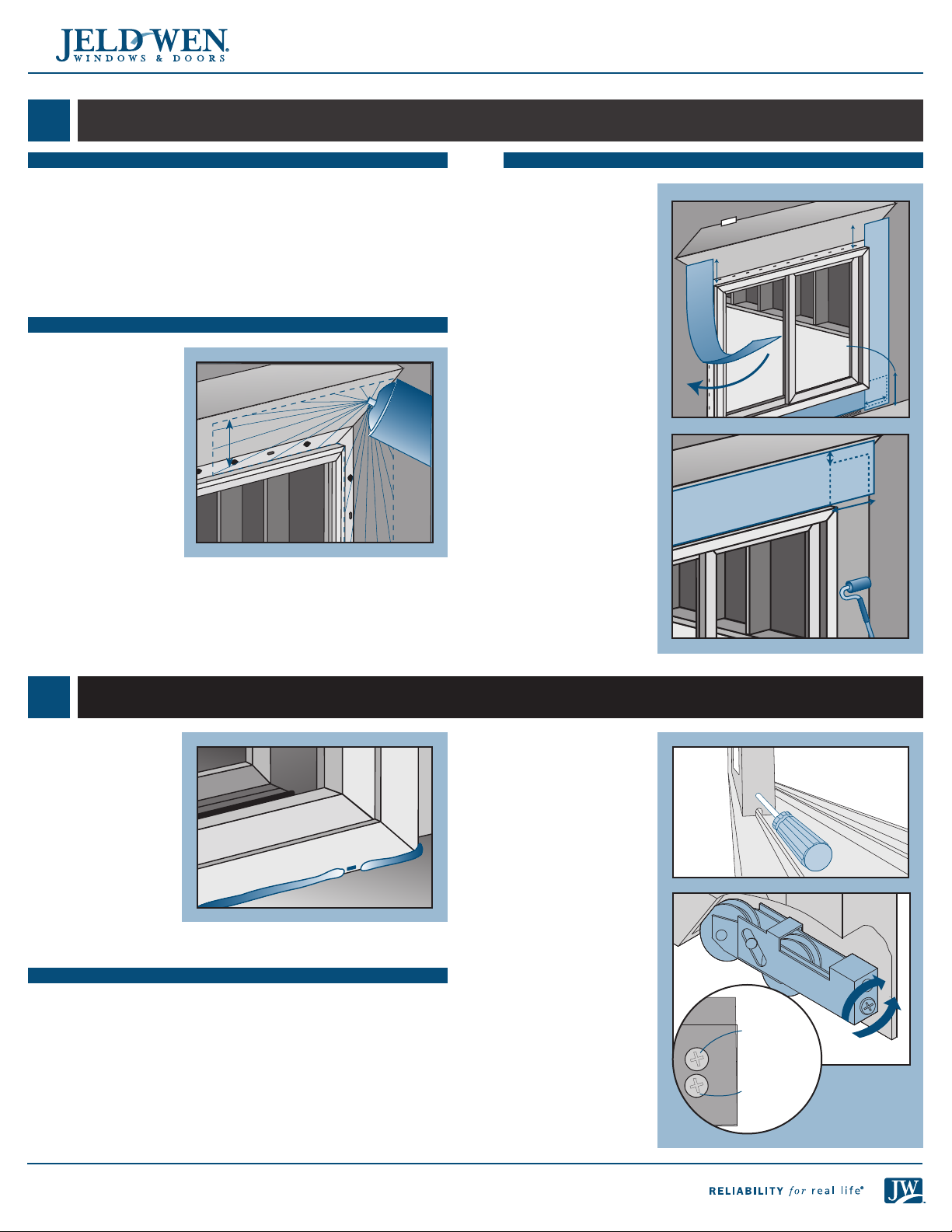
FLASH PATIO DOOR
PREPARE FLASHING
1. Cut pieces of self-adhesive ashing to length
as follows:
• One header piece 14" longer than the header
• Two side pieces: for continuous slab landings, 5" longer than the
sides, or for step-down landings, 5" + the height of the step
• For step-down landings only, one sill piece 10" longer than the sill
and 1" narrower than the height of the step
SPRAY ADHESIVE/PRIMER
2. Apply spray adhesive
per manufacturer’s
instructions
(protect door from
overspray) to nailing
n, sheathing,
and building wrap
6"
around the patio
door as shown.
APPLY THE SELF-ADHESIVE FLASHING
Note! Keep the edge
of the self-adhesive
ashing as close to
the patio door frame
as possible.
3. If applicable, center
and apply the sill
5"
5"
piece underneath
the sill (bottom
1/2" of the drain
screen must remain
visible).
4. Apply the side
e
v
i
s
e
h
d
A
y
a
r
p
S
pieces starting 5"
above the header.
5. Center and apply
the header piece
above the header.
Step
height
minus 1"
1"
5"
6. Press the ashing
down with a J-roller.
7"
7. Do not allow gaps
or bubbles beneath
self-adhesive
ashing (remove
and replace if
necessary).
8
COMPLETE INSTALLATION
1. For continuous slab
landings, apply a
1/4" bead of sealant
around the sill where
it meets the slab.
Leave 1" gaps at the
weep holes as shown.
2. Ensure sealant on
back dam of the sill
pan fully seals to
the inside face of
the sill. Apply more
sealant as necessary
to ensure an airtight
seal.
PATIO DOOR ADJUSTMENT
Roller Adjustment
Note! Adjusting door too high may allow water and air leakage. Adjust
rollers just high enough to clear sill track and still roll smoothly.
1. An adjustment screw is located on each lower end of the operating
panel.
2. Open operating panel enough to compare with frame jamb.
Note! Roller adjustment screws are in close proximity to the
attachment screw. Adjust only the lower screw as shown because
loosening the attachment screw will detach the roller from the
operating panel.
3. Using a #2 Philips
head screwdriver,
turn the adjustment
screw clockwise to
raise the panel, and
counterclockwise to
lower the panel.
4. Adjust as needed
until interlocks, grid
patterns and jambs
line up.
5. Test the operating
panel for proper
operation.
6. Re-apply the small
vinyl caps over the
roller adjustment
screw holes if
applicable.
Raise panel
Attachment
screw
Adjustment
screw
Lower panel
7
Page 8

INSTALLATION INSTRUCTIONS
for Fiberglass Gliding Patio Doors with Applied Nailing Fin (JII104)
8
COMPLETE INSTALLATION - CONTINUED
Lock Adjustment
Some locks will have a
single latch and some
will have a double
latch. Both adjust in the
same manner.
If the lock does not
properly engage the
strike plate:
• Loosen the strike
plate screws and
move up or down
until the latch
engages properly.
If the door does not
lock or is loose when
locked:
• Turn the latch
adjustment screw(s) in
1/2 turn increments:
clockwise to loosen or
counterclockwise to
tighten.
Lock hook adjustment
screw
Lock hook
adjustment
screw
AFTER INSTALLATION
• Install exterior wall
surface within seven
days of patio door
installation.
• Seal any gaps or
Gap
openings at end of
horizontal mull joints
with sealant.
Sealant joint
• Insulate the void
between the rough
Backer rod
opening and the
frame with low
expansion foam.
Seal with backer rod
and sealant on the
exterior.
• Clean and nish all
exposedinterior and
exteriorparts of each panel with at least two topcoats of an exterior
grade nish. Primer alone is not a suitable barrier.
• Protect recently installed units from damage from plaster, paint, etc.
by covering the unit with plastic.
Lock hook
adjustment
screw
Please visit www.jeld-wen.com for warranty, nishing instructions and care and maintenance information.
Thank you for choosing
©2014 JELD-WEN, inc.; This publication and its contents are owned by JELD-WEN, inc. and are protected under the U.S. Copyright Act and other
intellectual property laws. All trademarks, service marks, logos and the like (whether registered or unregistered) are owned or controlled by JELD-WEN,
inc. or others. Unauthorized use or duplication of JELD-WEN intellectual property is prohibited.
JELD-WEN reserves the right to change product specications without notice. Please check our website, jeld-wen.com, for current information.
8
(05/14)
 Loading...