

Page 1
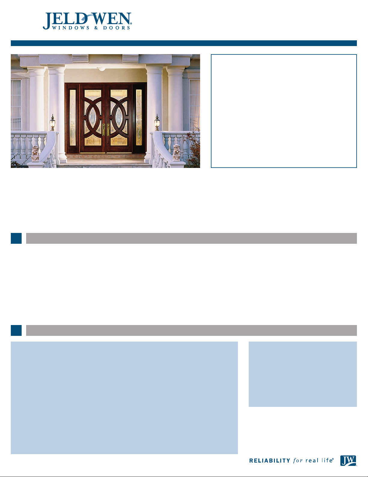
INSTALLATION INSTRUCTIONS
for Custom Wood and Fiberglass Door Systems (JII100)
Thank you for selecting JELD -WEN products. Attached
are JELD-WEN’s recommended installation instructions
for Custom Wood and Fiberglass doors. Read these
instructions thoroughly before beginning. They are
designed to work in most existing applications, however;
existing conditions may require changes to these
instructions. If changes are needed, they are made at the
installer’s risk. For installations other than indicated in
these instructions, contac t a building professional.
To adequately protect your door, please refer to
"Appropriate Protection for Exterior Doors" for
information on protection requirements at
www.jeld-wen.com/resources.
Not all door types may be installed into every wall condition in all areas.
Consult your local building code ofcial for applicable building codes and
regulations. Local building code requirements supersede recommended
installation instructions.
Please Note! Doors must be installed square, level and plumb and on
a at surface (without twist or warp). We also recommend that all
components be nished prior to installation. See our recommended
SAFETY & HANDLING
SAFETY
• Read and fully understand ALL manufacturers’ instructions
beforebeginning.
• Do not work alone. Two or more people are required. Use safe
liftingtechniques.
• Use caution when handling glass. Broken or cracked glass can cause
serious injury.
• Wear protective gear (e.g. safety glasses, gloves, ear protection, etc.).
• Operate hand/power tools safely and follow manufacturer’s
operatinginstructions.
• Use caution when working at elevated heights.
NEEDED MATERIALS & TOOLS
Installation Materials Required:
• Shims
• 1-1/2" 6d nish nails
• 3" 12d nish nails
• 3" corrosion resistant screws
• Sealant: We recommend OSI® QUAD® Max
Sealant or equivalent. This can be used
in any application and can be painted or
ordered in a color matched product, if
desired.
• Exterior waterproof construction adhesive
• Polyurethane low expansion Window and
Door foam: We recommend OSI® QUAD®
Foam or equivalent).
• Wood matched putty stick
• Sill pan made from plastic sheeting
• Set of ashings
• 4", 6", or 9" (as required by local code and
window conguration) wide self-adhesive
ashing: We recommend OSI® QUAD® Butyl
Flashing Tape or equivalent.
• Spray adhesive/primer for self adhesive
ashing. Such as Loctite® 300 or equivalent
• Backer rod 1/8" larger than the widest
portion of the gap (used in conjunction with
sealant bead).
nish maintenance instructions at www.jeld-wen.com/resources.
Poor installation or nish may result in denial of warranty claims for
operational or performance problems.
Note to Installer: Provide a copy of these instructions to the building
owner. By installing this product, you acknowledge the terms and
conditions of the limited warranty as part of the terms of the sale.
MATERIALS & PATIO DOOR HANDLING
• Heed material manufacturers’ handling and application instructions.
• Protect adhesive surfaces from dirt, moisture, direct sunlight and folding
over onto themselves.
• Handle in vertical position; do not drag on oor.
• Do not put stress on joints, corners or frames.
• Store door in dry, well-ventilated area to allow air circulation.
• Protect from exposure to direct sunlight during storage.
• Install only into vertical walls and when conditions and sheathing
aredry.
IF INJURY OCCURS, IMMEDIATELY SEEK MEDICAL ATTENTION!
Tools Required:
• 3-foot level
• 6-foot level
• Tape measure
• Hammer
• Finish nail gun
• Nail set
• Duckbill pliers
• 1/8" drill bit
• Caulking gun
• Safety glasses
• Miter saw
• 1" chisel or router
• Bar clamp
• Screw gun
• Utility knife
1
Page 2
Composite Jamb Routing and Installation Tips
1. Fastener and shim spacing should be set
at 16" or less.
2. To fasten the jamb parts to the stud wall,
pre-drill and countersink for at least 2"
fastening screws under the area covered
by the weatherstrip.
3. Make sure all countersunk holes are deep
enough to accommodate the screw
heads, and avoid over-torquing when
driving. The composite jamb material has
10 times the holding power of wood and
for that reason we recommend that a
light coat of screw lube or wax be
applied to all hinge and assembly screws
prior to driving.
4. Indicate shims to fasten through. Make
sure to locate one set of shims under
each hinge.
5. At least one screw per hinge should be
long enough to run through shim into
the supporting wall stud.
6. For radius systems, make especially sure
that the unit is sitting at on a level oor
and shim the head area with the door in
place to insure that the factory radius is
maintained and that there is an even
reveal around the door. An uneven oor
may make it difcult to maintain the
radius without trimming one jamb leg or
shimming the sill.
7. Finish nails are best driven with a
compressed air nail gun. Due to the
density of the material, it may be
necessary to use slightly more air
pressure than one would use for
softwood. The pressure required should
be similar to that needed for hard, dense
woods such as oak. As a cautionary note,
due to the nail holding power of the
composite materials, it may be difcult to
extract a mis-red nail. Should that
happen to occur, consider cutting the nail
off and driving any remaining portion
beneath the surface.
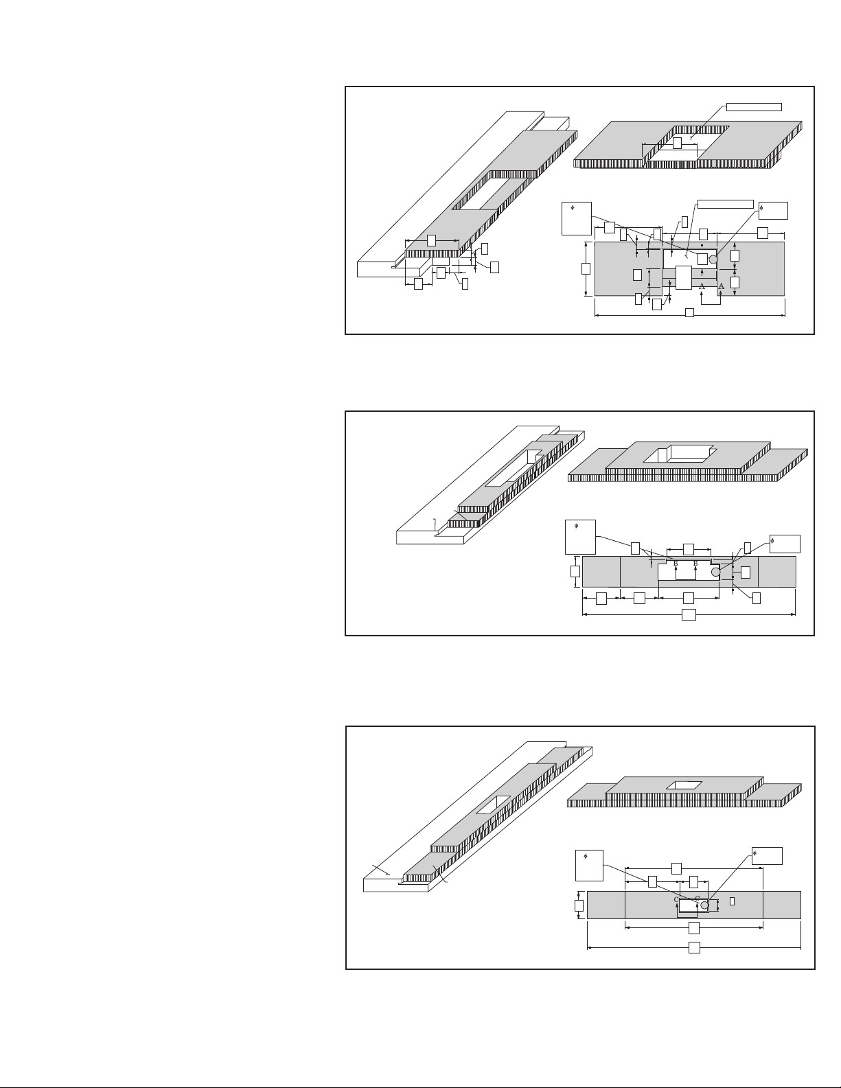
Hinge Pocket Template
for 4-1/2" x 4-1/2"
1_
4
SECTION A-A
2
1_
1
2
1_
2
4
5_
8
3_
4
Strike Plate Template
for Mission, Rocky
Mountain and
Omnia
Lockset
TEMPLATE
JAMB
Strike Plate Template
for Cylinder Lock
1_
3
8
SECTION B– B
1_
2
ROUTER
BIT
DIAMETER
ROUTER
BIT
DIAMETER
1_
2
2
HINGE TEMPLATE
5_
4
8
SIDE VIEW
HINGE TEMPLATE
9_
11_
5
16
5_
8
1_
4
2
1_
2
1_
1
2
3_
4
9_
32
5_
1_
3
3
32
16
16
1_
16
3_
3
4
4
HINGE
SIZE
5_
4
8
11_
1
16
1_
2
16
9_
3
16
15_
4
16
3_
17
8
5_
COLLET
8
DIAMETER
11_
5
16
1_
2
4
1_
2
4
5_
COLLET
8
3_
DIAMETER
8
1_
1
4
19_
32
8. Although it is possible to prepare for a
hinge or strike plate with a chisel, we
strongly recommend that the strike prep
be done with a router, collett and jig. If
necessary, the corners can be easily
squared with a chisel. The images show
three examples of templates used with
1/2" bits and 5/8" collets for common
hinge and strike plate applications. The
few minutes it takes to fabricate the
jig out of 5/8" plywood or MDF will
be more than offset after just a
couple doors.
JAMB
SECTION C– C
5_
COLLET
8
DIAMETER
1
TEMPLATE
ROUTER
BIT
DIAMETER
1_
2
4
1_
2
1_
11
4
1_
4
1_
2
2
4
1_
11
4
3_
17
8
2
Page 3
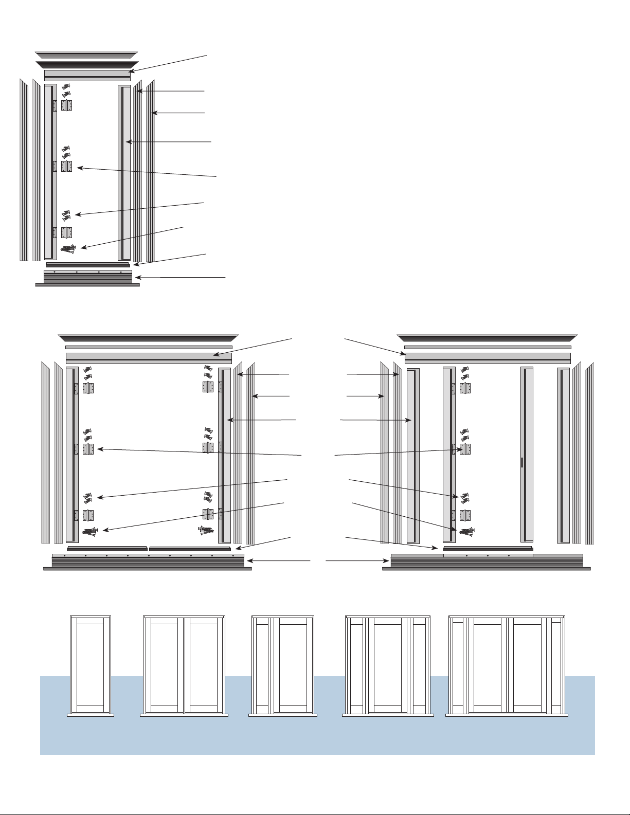
Custom Door System Overview
System 1
Head Jamb
(with weatherstrip)
Interior Trim
Exterior Trim
Jamb Leg
(with weatherstrip)
Hinges
Hinge Screws
Jamb Assembly Screws
Door Sweep
Sill
Check to ensure that all parts listed on the jamb boxes are
present and in good condition before removing existing entry
or beginning to install the new unit.
Please Note:
Check for hinges, door sweep, trim, jambs, sill and screws.
Head Jamb
(with weatherstrip)
System 2
Interior Trim
Exterior Trim
Jamb Leg
(with weatherstrip)
Hinges
Hinge Screws
Jamb Assembly
Screws
Door Sweep
Sill
Systems 3, 4, 5
System 1
Single Door
System 2
Pair of Doors
System 3
Door & Sidelight
System 4
Door & Pair of Sidelights
3
Pair of Doors & Pair of Sidelights
System 5
Page 4
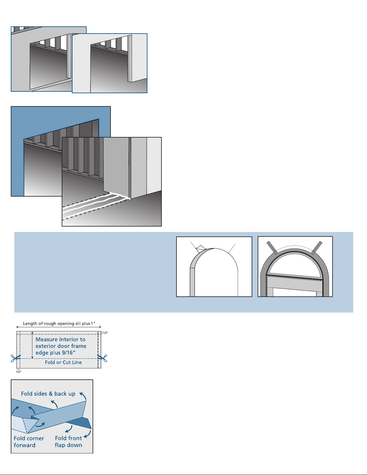
Prepare the Rough Opening
Step-down landing
Fig. 1 Cut building
wrap
Continuous slab landing
Fig. 2 Apply sealant
across sill
These instructions cover two door sill conditions: the step-down landing and
the continuous slab landing. The installation methods vary slightly between the
two landing types.
Prepare the rough opening. The rough opening is to be 3/4" wider and 3/4" taller
than the net outside jamb dimension of the unit. Check oor for level
(measurements must be within 1/8"). Check walls or studs for straightness
(measurements must be within 1/4") and plumb (measurements must be
within 1/8"). Correct before installing.
For doors with a curved transom top, see diagram 1 “Door with Curved
Transo m Top”. Rough opening must be level (measurements must be within
1/8") before starting; adjust as needed.
1. Clean rough opening and surrounding sheathing with a clean, dry cloth,
beginning at the top.
2. Trim building wrap ush with rough opening on header and sides; and
sill edge if door has a rise. Apply ve 3/8" beads of sealant across the sill
as follows (Fig. 2):
• One 1/2" from the interior and exterior edge.
• One across the center of the sill.
• One on each side where the jambs meet the oor.
Diagram 1. Door with Curved Transom Top
• Ensure framing is sufcient around transom perimeter to allow exterior
trim to be nailed every 8" to the structure.
• Prepare rough opening in same manner as for standard door (Fig. A).
• Install transom top in same manner as for regular door except for the
following:
- Apply ashing support in short 6"-12" sections around the curved
perimeter.
- Apply conformable self-adhesive ashing to backside of ashing
support and frame.
- Apply 6" wide conformable self-adhesive ashing onto ashing
support, sheathing, and building wrap around curved edge (Fig. B).
Prepare Sill Pan - The sill pan is a three-sided box made of plastic sheet material that sits in on
the rough opening. It is designed to catch water that inltrates the rough opening and divert it
to the outside. This prevents damage from water collecting on the rough opening sill. Door
installations that have a step-down landing (as opposed to a door that sits directly on a
continuous slab) have slightly different sill pans.
1. Prepare the sill pan as follows (Fig. 3):
• For a 2" x 4" wall, the width of the plastic sheeting should be at least 6".
Fig. 3 Sill pan template
Fig. 4 Fold sill
pan
• For a 2" x 6" wall, the width of the plastic sheeting should be at least 9".
• The length should be determined by measuring the length of the rough opening plus 1".
2. Crease lines in sill pan using a straight edge as follows (Fig. 3):
• Lightly crease a line inset 1/2" along both ends and one side of the plastic sheeting.
• Measure the width of the door frame (not including the brickmold), and add 9/16".
• Take this distance and measure out from the back side; crease a line the length of the
plastic sheeting.
3. Cut 1/2" in on both ends of this line (Fig. 3).
4. Fold the sill pan as follows:
• Fold the three 1/2" sides up; use duckbill pliers to fold corners to outside of pan on short
sides (Fig. 4).
Fig. A Cut back building wrap Fig. B Conformable ashing
4
Page 5

Prepare the Rough Opening - Continued
• For door with step-down landing: fold down at remaining crease line (Fig. 5).
• Trim height of fold-down to rise of step if necessary.
• For door on continuous slab, cut along the remaining crease line.
5. Place sill pan in rough opening so the open side faces the exterior.
Fig. 5 Finished sill pan for step down landing
S
p
Fig. 6. Apply adhesive spray
r
a
e
v
i
y
s
e
A
h
d
Fig. 7 Cut self-adhesive ashing
NOTE: Door sits inside sill pan; back dam of the sill pan should just clear the
back edge of door sill when it is placed in the rough opening.
1. Coat the sill pan with spray adhesive extending 3" up both side jambs; spray the
vertical face of the rise, if applicable, as shown in Fig. 6.
(Follow manufacturer‘s instructions for tack time.)
2. Apply self-adhesive ashing to the sill pan oor as follows:
• Cut adhesive ashing to sill length; for continuous slab, cut to width of sill
pan.
• Remove backing paper.
• Carefully apply to rough opening sill, ush with back dam of sill pan and fully
covering the bottom of the sill pan.
- Fold at onto rise (if applicable) or cut to sill pan width if on continuous
slab.
• Smooth out any bubbles or creases with a j-roller.
3. Apply self-adhesive ashing to lower corners as follows:
• Cut two pieces (one for each corner of the rough opening sill) 6" x distance
between the exterior and the interior edge of the door frame + 3".
• For doors on continuous slab, cut out the inside corner as shown in Fig. 7:
- Remove paper backing from one piece.
- Adhere to one bottom corner tightly at 90˚ with 3" up the side and wrap
ashing onto wall sheathing (Fig. 8); do not stretch or tear ashing;
eliminate as many wrinkles as possible.
Fig. 8 Apply self-adhesive tape (continuous slab)
• For step-down landings:
- Remove paper backing from one piece.
- Adhere to one bottom corner tightly at 90˚ with 3" up the side and overlap
onto the vertical face of the rise (Fig. 9); do not stretch or tear ashing;
eliminate as many wrinkles as possible.
- Press self-adhesive ashing tight into corners with j-roller.
- Repeat in opposite bottom corner.
4. Seal back corners of sill pan with sealant (Fig. 9).
Fig. 9 Apply self-adhesive ashing (step-down landing)
5
Page 6

Assemble Door Jamb Components
1. Lay jamb components out on a at protective surface prior to assembly (refer to
photos on page 1):
A. SYSTEMS 1 & 2 – Two jamb legs, one header, one sill.
B. SYSTEM 3 – Two jamb legs, one mull post, one header, one sill
C. SYSTEMS 4 & 5 – Two jamb legs, two mull posts, one header, one sill.
2. Prior to assembly, apply a light bead of caulk along all connecting surfaces of jamb
Fig. 10
components for sealing and adhesion (Fig. 10).
3. Attach and fasten jamb legs to the head jamb, using 1-1/2" screws into the pre-drilled
holes on the jamb leg. Make sure the edges of the head and side jamb line up and are
even with each other. Snug screws so corners are square and tight, with no gaps (Fig.
11 & Fig. 12).
4. Attach and fasten jamb legs to sill using 1-1/2" screws into pre-drilled holes on
outside jamb (Fig. 13).
SYSTEMS 3, 4 & 5 – Attach mull post into notch at sill. Fasten using 1-1/2" screws into
pre-drilled holes from bottom of sill into mull post (Fig. 14).
Fig. 11
Fi g. 12
5. Clean up any excess caulk.
Fi g. 13
Fig. 14
6
Page 7

Install Jamb System
Fig. 15
Fig. 16
1. With jamb system assembled, tip into rough opening, checking for good t
(Fig. 15). Mark exact location of sill on oor for construction adhesive and future
t, then remove unit.
2. Installation of sidelights (if not applicable, continue to Prepare Jamb System for
Installation on page 11)
A. Sidelight top, bottom and side edges must be sealed before installation into
the jamb.
B. Insert sidelight into the jamb in the direction as marked from the factory.
Sidelight for hinge side has pre-drilled pilot holes for hinge screws. Check for
t, then remove.
C1. For Custom Fiberglass Doors Only: Insert weatherstrip in the kerfed area
around the sidelight of the jamb. Once the door is completely installed, the
nished trim strip may be applied with a 1-1/2" 6d nish nail. (See Fi g . 16 .1
for details.)
C2. For Custom Wood Doors: To weatherproof sidelights, apply a bead of
caulk along the inside rabbeted corner the entire length of the sidelight jamb
leg, sidelight mull post, sidelight head jamb, and sidelight sill (Fig. 16).
D. Insert sidelights back into jamb.
E. Use bar clamps to tighten jambs to sidelight.
F. Anchor jamb leg to sidelight through back of rabbeted portion of jamb with
1-1/2" screws at top, bottom and center. More anchor screws may be
necessary on larger sidelights (Fig. 17).
G. Anchor hinge side mull post to sidelight using two 2" brass screws though
hinge (Fig. 18).
H. Anchor strike side mull post to sidelight, using a 1-1/2" screw under lock
strike location (Fig. 19). Anchor top of mull post to sidelight using two
1-1/2" nish nails approximately 2" down from head jamb through rabbeted
face of jamb. Anchor bottom of mull post to sidelight using two 1-1/2" nish
nails approximately 2" up from sill into rabbeted portion of mull post.
NOTE:
No screw holes or nail locations are marked on the strike side mull post.
Fi g. 17
Fig. 18
Fig. 19
Fi g . 16.1
7
Page 8

Prepare Jamb System for Installation
Jamb and Door Installation
1. Tip jamb unit into rough opening, paying close attention to prior marking for sill location.
2. CHECK SILL FOR LEVEL. Correct before installing (Fig. 20).
3. Checking jambs for straightness, level and plumb, apply shims from interior and exterior of
house as follows: (These numbers and locations of shims are meant only to serve as a
minimum requirement. Depending on the application and size of the unit, more shims may
be required.)
A. SYSTEMS 1 & 2 (Fig. 21); shim as follows:
• Shim the jambs as follows:
Fig. 20
• Behind each hinge.
• At the top and bottom of each jamb (at the pre-drilled holes behind the
weatherstrip).
• Behind the strike plate.
• Head jamb at center and 6" from each end.
• For 8' doors, more shims are needed at the jambs.
B. SYSTEMS 4 & 5 (Fig. 22); additional shimming as follows:
• On the sidelight jamb leg at approximately 2" and 30" from both the top and
bottom of the frame.
• Above the head jamb at the center of the door(s) and directly above the mull.
C. SYSTEM 3; additional shimming as follows:
Fig. 21
• On the sidelight jamb leg and the strike or hinge jamb leg at approximately 2" and
30" from both the top and bottom of the frame.
• Above the head jamb 6" from each corner, at the center of the door and directly
above the mull.
NOTE:
COMPOSITE FRAME INSTALLATION
RECOMMENDED PRACTICES FOR JAMB INSTALLATION
A. Fastener and shim spacing should be set at 16" or less.
B. Pre-drill and countersink for 2" fastening screws under the area covered by the
weatherstrip.
Fig. 22
C. Index the shims to fasten through and make sure to locate one set of shims under
each hinge.
D. At least one screw per hinge should be long enough to run through shim into the
supporting wall stud.
Fastening casing and brickmold should be the same as for any wood jamb. Any strike prep
or other machining can be made with traditional tools, etc.
4. Cross side jambs with string, checking for square, and plumb to ensure no rack. Adjust
shims as necessary (Fig. 23).
Fig. 23
8
Page 9

Attach Jamb to Studs
Fig. 24
Fig. 25
1. Temporarily fasten jamb to studs:
A. SYSTEMS 1, 2 & 3 - Fasten using 3" screw through top and bottom pre-drilled anchor
holes behind weatherstrip (Fig. 24).
B. SYSTEM 4 - Tightly installed shims should be enough to hold unit.
C. SYSTEM 5 - Fasten by partially driving one 3" nish nail through both the top and
bottom shim of the sidelight jamb legs (Fig. 25).
2. Attaching jamb to studs
NOTE:
Apply lubricant (wax or bar soap) to screw threads before driving screws.
A. SYSTEMS 1 & 2:
• Fasten jamb leg to stud by using 3" corrosion resistant screws through both top and
bottom pre-drilled anchor holes behind weatherstripping on hinge side jamb, drive
two 2" brass nish screws into stud through hinge (Fig. 26). If applicable, drive
3" corrosion resistant screws through the jamb at strike plate location. Fasten head
jamb by driving 3" screw through pre-drilled anchor holes behind weatherstrip.
• Check unit for square, plumb and even door reveal.
• If necessary, drill and countersink holes behind weatherstrip then fasten with 3"
corrosion resistant screws at additional locations on jamb legs.
Fig. 26
Fig.27
• At approximately the same level as the anchor screws and hinges, drive two 3"
nish nails through face of jamb into stud to help secure jamb (Fig. 27).
NOTE:
Screws and nails must go through the shims.
B. SYSTEMS 4 & 5:
• Anchor jamb legs by driving a minimum of two 3" nish nails through the exterior
face of the jamb into the stud at both 2" and 30" from the top and bottom of the
unit (Fig. 28). Refer to Fig. 22 for nailing locations. Additional anchoring locations
may be necessary depending on size of the unit.
• Anchor head jamb by driving two 3" nish nails through the face of the jamb
into the stud at the center of each door and sidelight at the shim locations.
IMPORTANT:
Nails must go through the shims.
C. SYSTEM 3:
• Attaching jamb to stud is combination of the two above procedures.
Fig. 28
9
Page 10

Finishing Installation
Fig. 29
1. Structurally secure sill as follows:
NOTE:
For wood framing, use #8x3" corrosion resistant screws. For concrete, use
3/16" x 2-1/2" self-tapping concrete screws.
A. Coat threads of screws with sealant before insertion into hole.
B. Drill appropriate pilot holes as necessary.
C. Cover top of screws with sealant.
Da. If door has a traditional threshold, secure as follows (Fig. 29):
• For single panel swing doors, place two structural screws 6" from each end.
• For multiple panel doors, replace the existing screws at each end of the
threshold and every other existing screw in between with structural screws.
Db. Some inswing doors require an adjustable threshold; if adjustable threshold
(Fig. 30):
Backer Rod
& Sealant
Backer Rod & Sealant
Fig. 30
Fig. 31
Fig. 32
• For single panel swing doors, place two structural screws 6" from each end.
• For multiple panel doors, place a screw in front of every other screw location
into the sill.
2. Hang the door slab in the frame by screwing the hinges in place on the frame.
Assure proper t.
3. On the exterior, apply a continuous sealant joint between the frame
and the rough opening at the jambs and header using backer rod
and sealant (Fig. 31).
4. On the interior apply low pressure foam between the outside of jamb and the stud
to seal any gaps (Fig. 32).
NOTE:
Follow manufacturer's instructions for proper low pressure foam usage.
5. Installing hardware:
A. Install the lock set, following manufacturer’s instructions. Use chisel or router to
mortise out for strike plate on jamb or astragal.
B. Install the door sweep onto the bottom of the door. Attach using 1/4" screws on
face of door sweep. Run a bead of caulk on the top exterior outer edge to prevent
water from entering the sweep
(Fig. 33). 6. Installing exterior and interior trim
Fig. 33
Fig. 34
A. Trim any sealant or shims protruding from the jamb.
B. Measure, cut and set one trim leg. Reveal of the trim to be approximately 3/16"
from inside edge of jamb. Measure both ends of head trim, cut, if necessary,
then set (Fig. 34). Measure, cut and set other trim leg.
IMPORTANT:
Trim is intentionally left long for more exibility in the eld. It may be
necessary to cut to length and miter depending on your application.
C. Anchor the casings to jamb with 1-1/2" or 3" nish nails every 12" to 18".
D. JELD-WEN recommends running a bead of caulk around the edge of the
exterior trim where it meets the wall.
7. Fill all nail holes with a wood matched putty stick.
10
Page 11

Finishing Installation
Fig. 35
8. JELD-WEN has included a set of 1-3/4" by 1-1/4" compression
weatherstrip wedges. Install these at lower rabbeted corners of the
jambs to help ensure a weathertight seal (Fig. 35).
9. Optional Transom Installation
A. Run a generous bead of caulk on the top of the door head jamb.
Fig. 37
Fig. 39
Fig. 36
B. Set the transom jamb on the door head jamb.
C. Drill countersunk pilot holes 12" from both ends and in the center
of the rabbeted portion of the bottom transom jamb into the door
head jamb.
IMPORTANT:
Stop the drill at 1-1/4" depth.
D. Fasten transom jamb to head jamb with 1-1/4" screws into pilot
holes (Fig. 36).
E. Shim transom jamb approximately every 16" to 24".
F. Drill countersunk pilot holes on the rabbeted portion of the transom
jamb through the location of every shim (Fig. 37). Fasten the
transom jamb to the studs through these pilot holes with 3"
corrosion resistant screws.
G. To secure the jamb to the studs at every shim, drive two 3" nish
nails through the face of the jamb into the stud (Fig. 38).
NOTE:
Steps 8-11 only apply if the transom sash was not factory
installed.
H. Install transom sash to check for t, then remove.
Fig. 38
Fig. 40
Fig. 41
I. Apply a bead of caulk along the inside corner of the rabbeted
ransom jamb (Fig. 39).
J. Install transom sash.
K. To secure transom sash to jamb, set quarter round stop and fasten
with 1-1/2" nish nails (Fig. 40).
L. Measure, trim and set interior and exterior trim to transom jamb.
Fasten trim to frame with either 1-1/2" or 3" nish nails.
NOTE:
Trim is run long to allow more exibility in the eld.
M. Measure cut and set mullion covers. Caulk and fasten with 1-1/2"
nish nails (Fig. 41).
N. Fill all nail holes with wood matched putty stick.
11
Page 12

Trouble Shooting
Fig. 42
Fig. 43
Fig. 44
Weatherproofing the Door
Fig. 45A & B
Drip Cap installation
Fig. 46
Fig. 47
Problem #1
Reveal between door and lock side jamb is too tight (Fig. 42).
Causes:
1. Hinge leafs not set ush into jamb and door.
2. Hinge leafs bent at knuckle, pushing door towards jamb.
3. Hinge side jamb over-shimmed at hinge locations, pushing door towards
lock jamb.
4. Lock side jamb over-shimmed.
5. Door not anchored properly to stud at top hinge location.
Problem #2
Reveal between door and jambs is too wide (Fig. 43).
Causes:
1. Check reveal on hinges side to see if door is sagging in opening. Sagging
may be due to the following:
A. Door not anchored properly to stud at top hinge location.
B. Top hinge leaf is bent at knuckle.
C. Top hinge not set ush into jamb or door.
2. Jamb not square. Check the following:
A. Sill for level.
B. Head jamb for level.
C. Jamb over-shimmed.
Problem #3
Top or bottom corner of door projects into house past jamb (Fig. 44).
Causes:
1. Hinges not all set tight against back set of hinge prep on jamb or door.
2. Jamb is racked, one side of jamb kicks into the house while the other jamb
kicks outside. This can be checked by using a 6-foot level on each jamb, or
cross sighting the jambs with a string. The strings should just touch where
they cross in the middle. If there is a gap between these two strings, this
is the distance the frames are racked.
1. Cut a piece of galvanized drip cap the length of the header brickmold plus 1/4" to allow for
1/8" overlap past the ends of the header brickmold.
• Apply 1/4" bead of sealant to top of the header brickmold along the front and side edges
(Fig. 45A).
• Nail drip cap in place; apply sealant to side edges (Fig. 45B).
2. Drive all nails into the brickmold completely but do not overdrive; do not dent brickmold; set
the nail below the surface.
3. Apply sealant to the two upper corners as follows:
• Follow sealant manufacturer’s instructions for surface preparation and application.
• Apply bead 1/4" wide to corners extending 1" along both legs of the corner.
• Use the back of a spoon (or similar shape) to form sealant into llet shape (Fig. 46).
4. Apply additional sealant as follows:
For doors with step-down landing:
• Apply a 1/4" bead of sealant underneath the sill, leaving a 1" gap 6" from each end (Fig.
47).
For doors on continuous slab:
• Apply a 1/4" bead of sealant around the nose of the sill where it makes contact with the
slab or step leaving a 1" gap 6" from each end of the sill nose.
Please visit www.jeld-wen.com for warranty, nishing instructions and care and maintenance information.
Thank you for choosing
© 2009, JELD-WEN, inc. | JELD-WEN Reliability for Real Life, and the JW icon are trademarks or registered trademarks of JELD-WEN, inc., Oregon, USA.
All other trademarks are the property of their respective owners.
12
(05/14)
 Loading...