

JEFF ROWLAND Model 8T, Model 8Ti Owner's Manual

JEFF ROWLAND
DESIGN GROUP

Model 8T/Ti
Stereo Power Amplifier
Owner’s Manual

Introduction
W
elcome to the Jeff Rowland Design Group “family” and congratulations on your purchase of what is unquestionably
one of the world’s finest audio power amplifiers.
þ With its combination of features such as numerous function control
and interconnection possibilities, precision electronic circuitry and accurately machined chassis components throughout,
your Model 8T/Ti Amplifier will offer you many years of musically satisfying enjoyment.
þ Please take a few moments to
read the remainder of this Owner’s Manual. A thorough understanding of the operational features will allow you to gain
the maximum performance and ease of use for which this Amplifier was designed.
þ Please note that your Model 8T/Ti
Stereo Amplifier serial number begins with the letter A. This number is recorded below and is also located on the rear
panel of the chassis. Please include this number with any correspondence regarding your Model 8T/Ti Amplifier.
þ It has
been my joy to create an audio component of enduring value which will reflect a higher ideal of musical and artistic
expression. It is my hope that these qualities will enrich your experience of ownership.
Enjoy the music!
Jeff Rowland
President
þ Jeff Rowland Design Group, Inc.
2911 North Prospect Street
Colorado Springs, CO 80907
Phone: 719/473-1181
Fax: 719/633-4158

Product Features
þ XLR Balanced Input jacks for balanced (Differential Mode™) system
configurations
þ RCA Input jacks for unbalanced (single-ended) system configurations
þ Two parallel connected speaker output connectors for both right and
left channels
þ User-selectable overall gain of 26 or 32 dB
þ User-selectable input impedance of 36k or 600 ohms for both balanced
and unbalanced inputs.
þ User-selectable absolute phase on balanced input
þ User-selectable input muting
þ User-selectable switching between balanced and unbalanced inputs
þ Front panel standby/power button illumination can be turned off
during listening
þ Optional remote (wired or wireless) power ON/OFF switching
þ Automatic temperature stabilizing circuitry maintains constant
operating temperature
þ Standby power condition reduces warm-up time
þ Fail-safe operation provided by user-resetable AC and DC magnetic
circuit breakers located on rear panel
þ Quiet, transient-free operation during power and function
mode switching
þ Automatic input muting under anomalous input or output operating
conditions
þ Balanced Differential Mode™ circuit topology implemented from input
to output
þ Plug-in modules, containing critical electronic circuitry, enhance
thermal stability, mechanical integrity and serviceability
þ Low-resonance, structurally integrated chassis of precision machined
aluminum alloy components
Introduction / Product Features
1
2
3
4
5
Contents

Initial Inspection
I
nspect the shipping container for damage. If the shipping container,
packing material, amplifier or accessories are damaged or missing, notify
your dealer and the shipper (if a claim is to be made). Note: Many shippers
require notification and an inspection within twenty-four (24) hours of
delivery to ascertain the nature of damages incurred.
Your Model 8T/Ti Amplifier has undergone extensive performance
evaluations, listening tests, quality control inspections and a minimum
seventy-two (72) hour burn-in period prior to shipment and should be in a
perfect operational condition upon receipt. If the Amplifier does not operate
correctly, please notify your dealer immediately.
We strongly suggest that you save all packing materials. If the Amplifier is
returned to your dealer or Jeff Rowland Design Group, the original packing
materials must be used for shipment. Neither Jeff Rowland Design Group
nor the shipper can be held responsible for damages incurred during transit
if the original factory packing is not used. All factory returns require that a
Return Authorization number be issued by Jeff Rowland Design Group prior
to shipment.
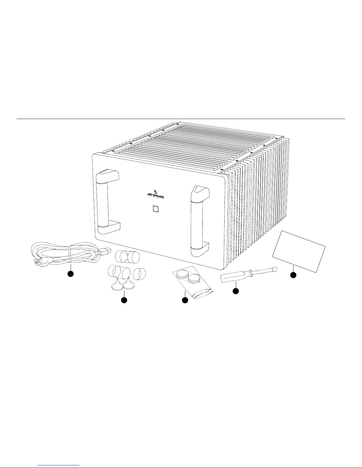
Contents
E
nsure that all of the auxiliary components listed below are enclosed
within the accessory box. Refer to the diagrams illustrated above and verify
the components included.
1 AC power cable
2 Four (4) spiked coupling interface supports
3 Four (4) compliant isolation interface supports
4 One (1) speaker terminal hand wrench (7/16 inch)
5 One (1) warranty card (in some countries warranties are provided by
the respective importer)
Initial Inspection / Contents
 Loading...