

Page 1

Model 12
Model 12
Mono Power Amplifier
Mono Power Amplifier
Owner’s Manual
Owner’s Manual
Page 2

IntroductionIntroduction
WWelcome to the Jeff Rowland Design Group “family” and congratulations on your purchase of what is
JJeff Rowland Design Group, Inc.
unquestionably one of the world’s finest audio power amplifiers. WWith its combination of features such as
numerous function control and interconnect possibilities, precision electronic circuitry, and accurately
machined chassis components throughout, your Model 12 Mono Power Amplifier will offer you many
years of musically satisfying enjoyment. PPlease take a few minutes to read the remainder of this Owner’s
Manual before proceeding with the installation of the amplifier. A thorough understanding of the
operational features will allow you to gain the maximum performance and ease of use for which this
amplifier was designed. PPlease note that your Model 12 Mono Amplifier serial number begins with the
letter “F.” This number is recorded below and is also located on the rear panel of the chassis. Please
include this number with any correspondence regarding your Model 12 Mono Power Amplifier. IIt has
been my joy to create an audio component of enduring value that reflects a higher ideal of musical
and artistic expression. It is my hope that these qualities will enrich your experience of ownership.
2911 North Prospect Street
Colorado Springs, CO 80907
TTelephone: 719-473-1181
FFax: 719-633-4158
EE-mail: [email protected]
WWeb: www.jeffrowland.com
Enjoy the music!
Jeff Rowland
President
Jeff Rowland Design Group
Page 3

Product FeaturesProduct Features
• XLR input connectors for balanced (Differential Mode) system
configuration.
• RCA input connectors for unbalanced system configurations.
• Selectable overall gain of 26 or 32 dB.
• User selectable switching between balanced and unbalanced
connections.
• 12V remote ON/OFF power switching connector.
• Automatic temperature stabilizing circuitry maintains constant
operating temperature.
• CE approved speaker output connectors requiring no tools for
• Automatic bias adjustment maintains optimal bias setting
regardless of source material or loudspeaker load.
• Standby power condition reduces warm-up time.
• Fail-safe operation provided by user-resetable thermal circuit
breakers located on power supply rear panel.
• Quiet, transient-free operation during power and function mode
switching.
• Automatic input muting under anomalous input or output
operating conditions.
• Fully-balanced Differential Mode circuit topology implemented
tight connections.
• Separate power supply featuring 2nd generation high-speed
switch mode circuit design.
• Parallel Balanced Input capability for multiple amplifier
connection in high current demand situations.
from input to output.
• Low resonance, structurally integrated chassis constructed of
precision-machined aircraft grade aluminum.
Page 4
ContentsContents
Model 12 Model 12
SectionSection
Model 12 Model 12
SupplySupply
DC Power DC Power
Supply CableSupply Cable
AC Power CableAC Power Cable
Warranty CardWarranty Card
AmplifierAmplifier
Power Power
Page 5

Initial InspectionInitial Inspection
ContentsContents
ContentsContents
IInspect the shipping container for damage. If the shipping
container, packing material, amplifier, or accessories are damaged
or missing, notify your dealer and the shipper (if a claim is to be
made) immediately. Note:Note: Many shippers require notification and
inspection within twenty-four hours of delivery to ascertain the nature
of damages incurred.
Your Model 12 Mono Power Amplifier has undergone extensive
performance evaluations, listening tests, quality control inspections,
and a minimum seventy-two hour burn-in period prior to shipment
and should therefore be in perfect operating condition upon receipt.
If the amplifier does not operate correctly, please notify your dealer
immediately.
We strongly suggest that you save all packing materials. If the
amplifier is to be returned to your dealer or Jeff Rowland Design
Group, the original packing materials must be used for shipment to
avoid damage. Neither Jeff Rowland Design Group nor the shipper
can be held responsible for damages incurred during transit if the
original factory packing is not used. All factory returns require that
Jeff Rowland Design Group issue a Return Authorization (RA) number
prior to shipment.
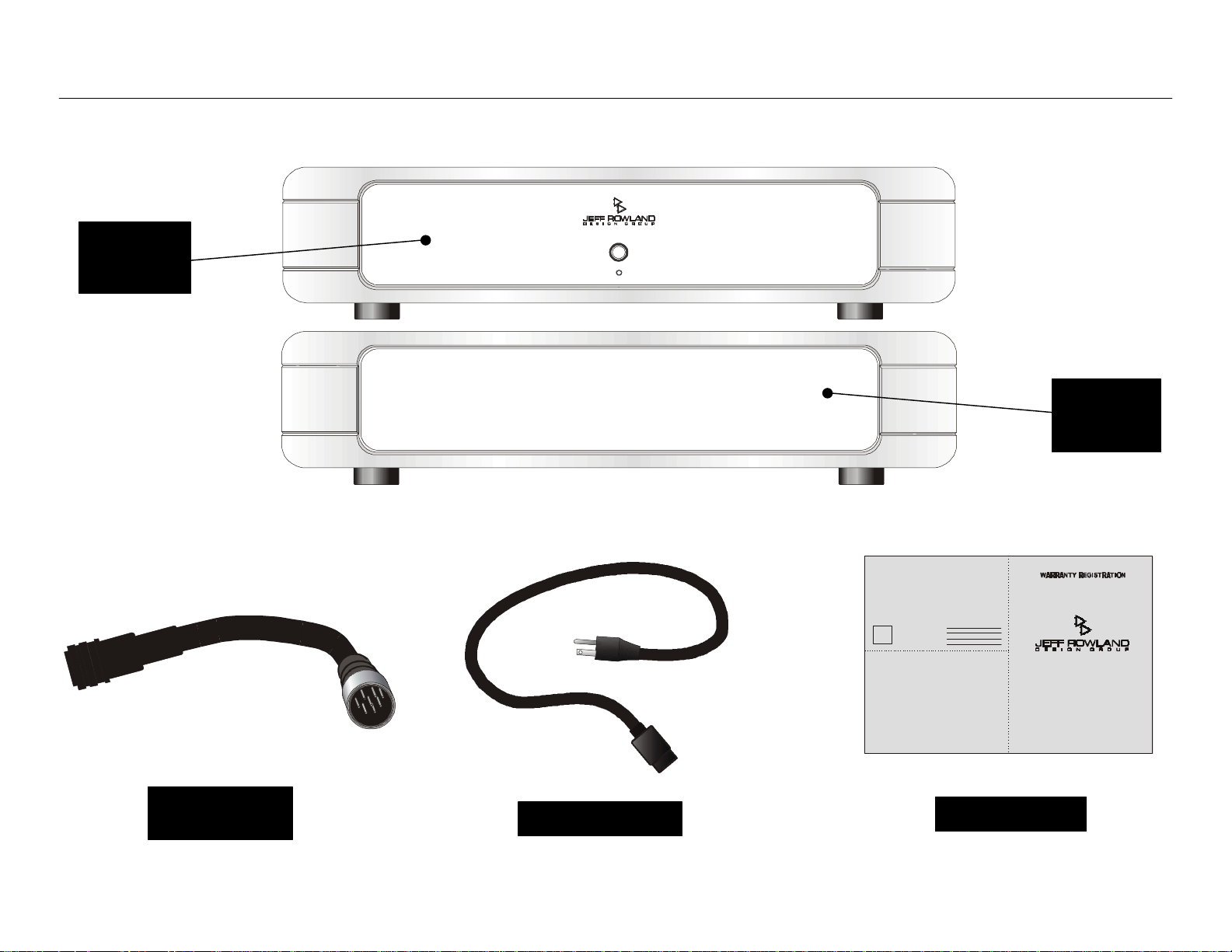
EEnsure that all of the auxiliary components listed below are enclosed
within the accessory box. Refer to the diagrams illustrated above
and verify the components included.
11 One AC Power Cable
22 One DC Power Supply Cable
33 One Warranty Card (In some countries, warranties are provided
by the respective importer.)
Page 6
Care, Cleaning, and MaintenanceCare, Cleaning, and Maintenance
Page 7

CareCare
CareCare
TThe Model 12 Mono Power Amplifier is finely constructed from pieces
of solid aluminum. The surface of the unit is cut in a unique process
that uses a diamond tipped blade. This process was refined over
many years to produce an artistic and attractive finish. The front,
top, bottom and side panels are then finished with fine automobile
polyurethane clear coat after a light anodizing to preserve the clarity
of the finish and are not raw or exposed metal.
Because the surface is not finished in the typical fashion of most
audio and video equipment, there are a few rules that must be kept
in mind when cleaning the equipment.
• Please allow the unit to cure for 6 months before attempting to
clean it. This will prevent small scratches from marring the
surface before the surface coating has had a chance to harden
completely.
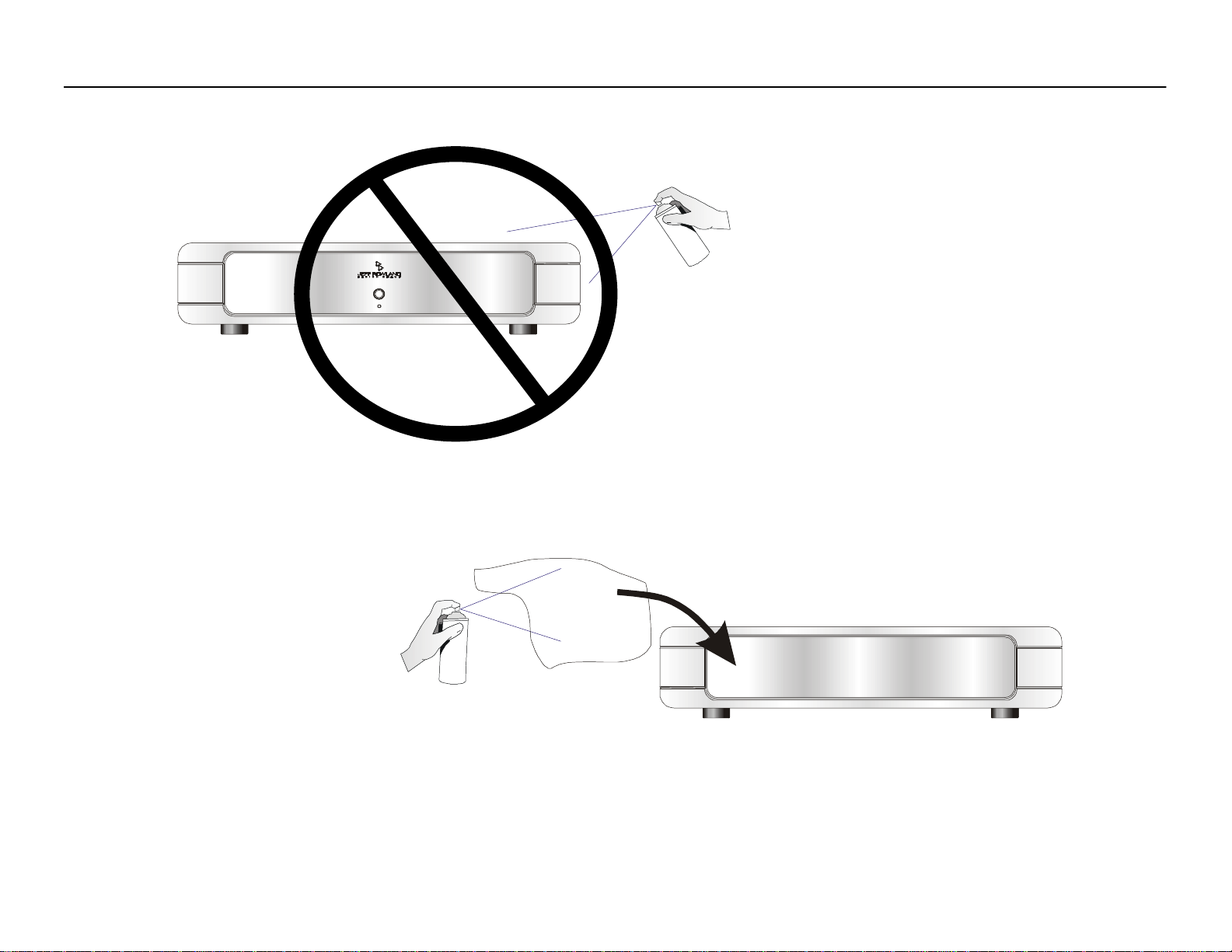
• The top cover, sides, and bottom cover can all be cleaned with
a soft cotton cloth (such as an optical lens cleaning cloth or fine
furniture polishing rag) dampened with plain water. Water should
be applied directly to the cloth and not the chassis. If a mark
has been left on the chassis, do not use any type of abrasive or
chemical cleaner to remove the mark. A very mild plastic or
glass cleaner that does not contain ammonia should be tried
only as a last resort. Please contact the factory before trying any
type of cleanser on the chassis other than water to clean the
unit.
based furniture wax or polish. Because of the fine finish of the
front panel, small scratches from the use of any other agent to
clean the front panel will become very visible. Again, the water
or polish should be applied to the cloth, not the chassis.
If you have any questions about the treatment or cleaning of your
Model 12 amplifier, please contact your dealer or the Jeff Rowland
Design Group factory before attempting to clean the chassis. The
use of a cleanser or abrasive to clean the chassis that has not been
approved by the factory will almost certainly damage the finish and
will not be covered under warranty.
MaintenanceMaintenance
AAll Jeff Rowland Design Group products are designed to provide a
lifetime of enjoyment and listening pleasure. The chassis is sealed to
prevent dust from entering and the interior of the chassis should not
need cleaning during the lifetime of the product. All internal circuitry
is self-adjusting or stable so no adjustments or maintenance of any
kind should be necessary over a lifetime of normal operation.
If the amplifier is ever in need of service, updating, or upgrading, it
should only be returned to an authorized repair facility or technician
for servicing. It is not recommended that the customer attempt to
disassemble or repair the unit and doing so may void your warranty.
• The front panel of the unit should never be cleaned with anything
other than a very soft cotton cloth and plain water or fine oil-
Page 8
Amplifier Front and Rear Panel Function ControlsAmplifier Front and Rear Panel Function Controls
NEUTRIK
Standby/Power ButtonStandby/Power Button
Power Indicator LEDPower Indicator LED
Input Select SwitchInput Select Switch
Amplifier Front PanelAmplifier Front Panel
Amplifier Rear Panel
NEUTRIK
PUSH
Page 9

Amplifier Front and Rear Panel Function ContAmplifier Front and Rear Panel Function Controlsrols
Control Control
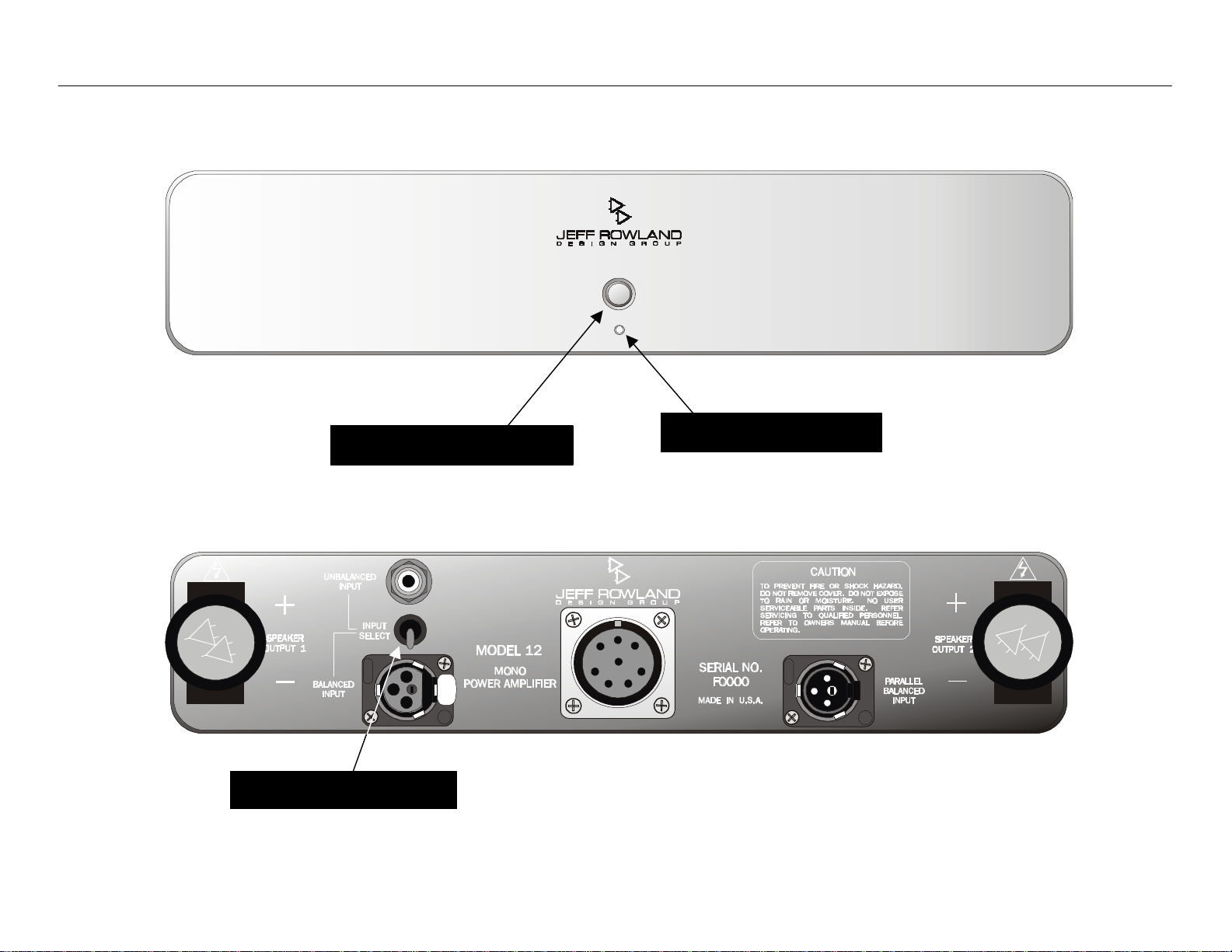
BBefore attempting any system interconnection, please familiarize yourself with the front and rear panel controls of the Model 12 Mono Power
Amplifier. The descriptions below refer to the diagrams above.
Front PanelFront Panel
11 FRONT PANEL STANDBY/POWER BUTTON: Press this button to
operate the amplifier. Press again to place the amplifier in
Standby mode. The small orange POWER INDICATOR LED will
illuminate when the amplifier is operational. When the POWER
INDICATOR LED is not illuminated, all amplifier inputs are muted
and internal circuitry reverts to power-saving (Standby) mode.
Anomalous operating conditions will place the amplifier in
Standby mode and will prevent the amplifier from being
switched back on again until such a condition is eliminated.
To avoid spurious noises, the amplifier should never be turned on
if the inputs on the rear panel are not connected.
Note:Note: All ON/OFF power switching should be initiated ONLY with
this button. The amplifier should never be disconnected from
AC power without first placing the amplifier in Standby mode.
Rear PanelRear Panel
(Note: If desired, the switch described below can be switched while
the amplifier is operational and playing music.)
11 INPUT SELECT SWITCH: This switch selects either the unbalanced
RCA inputs or the balanced XLR inputs. Note:Note: When the RCA
position is selected, pin 2 of the XLR is shorted to pin 1.
Page 10
Rear Panel Power ConnectionsRear Panel Power Connections
NEUTRIK
AC Power Cable AC Power Cable
DC Power Supply DC Power Supply
Cable ConnectorCable Connector
Volts AC Volts AC
IndicatorIndicator
NEUTRIK
Amplifier Rear Panel
PUSH
Power Supply Rear Panel
ConnectorConnector
Page 11

InstallationInstallation
Installation Installation
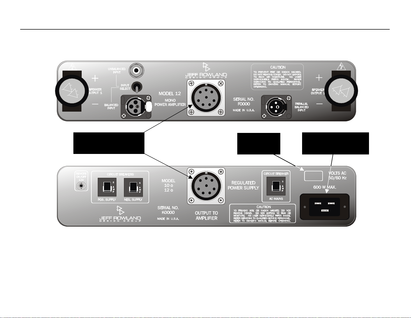
Rear Panel Power ConnectionsRear Panel Power Connections
LLocate the amplifier as close as possible to its final installation point.
Allow access to the rear panel for making connections.
The Model 12 Mono Power Amplifier is convection cooled,
eliminating the need for fan or forced-air cooling. When operating,
the chassis should have at least two (2) inches of air space around
the heatsink areas. Multiple chassis can be stacked vertically,
facilitating an upward flow of warm air currents throughout the
vertical heatsink areas. This upward flow must not be blocked or
recirculated around the chassis if proper cooling is to be
maintained.
Important:Important: Please strictly follow the steps in order as outlined below
before operating your Model 12 Mono Power Amplifier.
11 Verify that the VOLTS AC input identified on the rear panel near
the AC input socket is the same as the AC mains voltage in your
area. If the voltage does not match, do not connect the
amplifier to AC power and contact your dealer immediately.
22 Install the DC Power Supply Cable between the power supply
and the amplifier section. There is a slot cut in the edge of the
connector on each end of the cable, and this slot should be
aligned to face up. Use the knurled ring on the connector to
secure the cable to both the power supply and the amplifier.
33 Verify that the AC MAINS CIRCUIT BREAKER and the POSITIVE and
NEGATIVE SUPPLY CIRCUIT BREAKERS are closed.
44 Install the AC Power Cable between the amplifier and your AC
mains outlet.
Note: Note: If the amplifier is to be moved to another location, always
place the unit in Standby mode before disconnecting the AC power
cable from the AC mains wall outlet.
Page 12
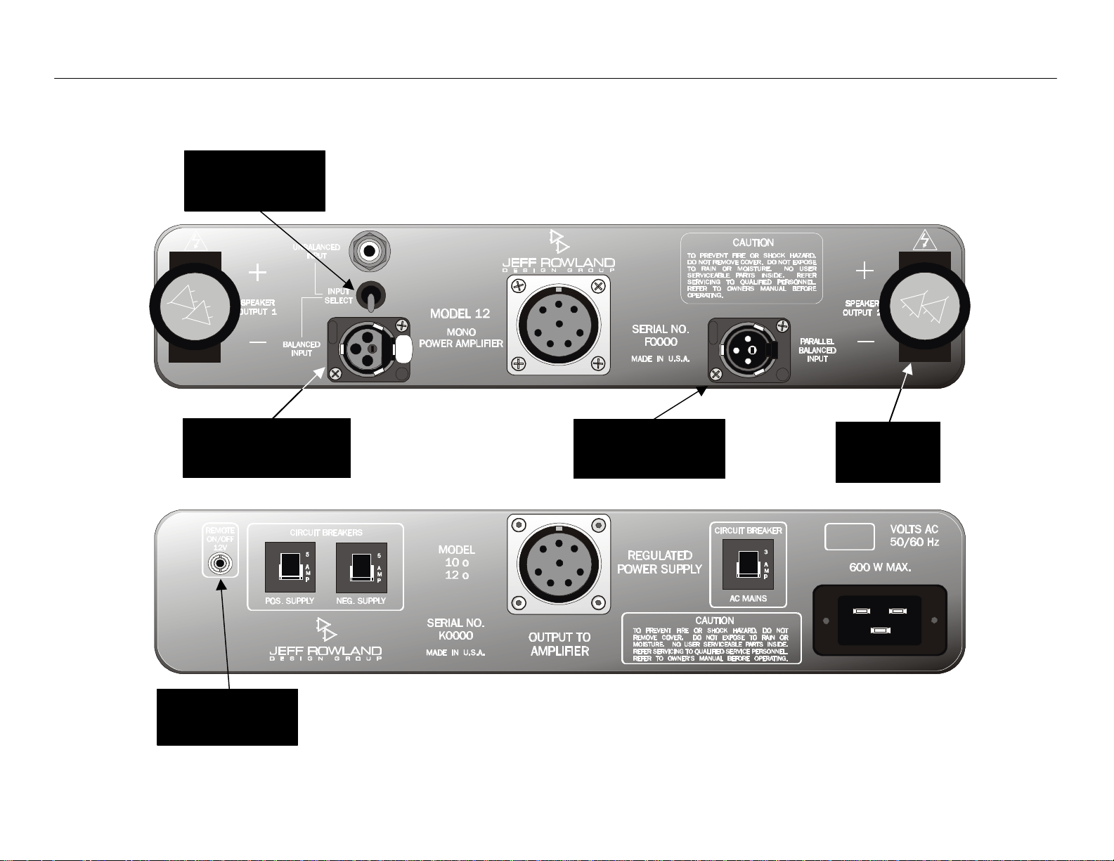
Signal Connections and RemoteSignal Connections and Remote
NEUTRIK
Balanced Input Balanced Input
12V Remote 12V Remote
ConnectorConnector
Input Select Input Select
Speaker Speaker
Parallel Input Parallel Input
SwitchSwitch
ConnectorConnector
Amplifier Rear Panel
NEUTRIK
PUSH
ConnectorConnector
Output Output
Power Supply Rear Panel
Page 13

Signal Connections and RemoteSignal Connections and Remote
Signal & 12V Signal & 12V
TThe Model 12 Mono Power Amplifier offers unprecedented
compatibility with associated audio components. When
Connecting or disconnecting speaker or interconnect cables, it is
necessary to place the amplifier in Standby mode (orange POWER
INDICATOR LED on the front panel OFF).
11 If you are using balanced XLR interconnects from your
preamplifier or source component, position the INPUT SELECT
switch to BALANCED INPUT. If you are using unbalanced RCA
interconnects, position the INPUT SELECT switch to UNBALANCED
INPUT.
22 Connect your interconnect cable to one input – either BALANCED
INPUT or UNBALANCED INPUT.
33 The PARALLEL BALANCED INPUT connector is for secondary
components requiring a parallel input signal. The output from
this connector is identical to the signal at the BALANCED INPUT.
This connector should be used for applications such as driving a
secondary amplifier for bi- or tri-amplification purposes or a
powered subwoofer. For parallel connection instructions, please
see the following two pages of this manual.
Note:Note: This connection should not be used with balanced XLR to
unbalanced RCA adaptors, as it will nullify the balanced audio
signal throughout the entire audio chain, including source
components.
44 A slight mechanical click may be heard when the balanced XLR
interconnect cables are correctly installed and locked. The
unlocking tab (located on the input connector and labeled
“PUSH”) must be pressed to disconnect the XLR interconnect
cable from the amplifier.
(usually red) loudspeaker cable spade terminal to the positive (+)
binding post and the negative spade terminal (usually black) to the
negative (-) binding post. Secure the loudspeaker connection by
tightening the knob securely with your fingers.
+ Warning:Warning: Both positive and negative outputs are electrically
active with respect to chassis and/or system ground potential.
Therefore, this amplifier cannot be used in certain loudspeaker
switching configurations, such as those used in retail
demonstrations. Failure to avoid these precautions can result in
damage to the amplifier and will void the warranty.
12V Remote12V Remote
11 AA 12V REMOTE ON/OFF mini-plug connector is provided on the
rear panel of the power supply for remotely switching the
amplifier between Operational and Standby modes. The
connections on this connector parallel the electrical contacts of
the FRONT PANEL STANDY/POWER button. When connected to
another component with the proper circuitry, the amplifier can
be turned ON and OFF remotely. Please contact your dealer for
further information about this feature.
55 Unscrew the knob that secures the speaker output connector on
for the SPEAKER OUTPUT and pull the securing block out far
enough to allow access to the binding posts. Install the positive
Page 14
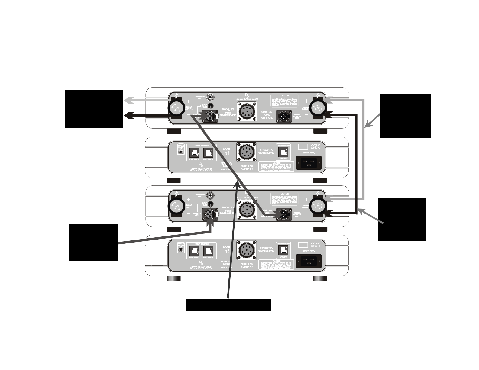
Parallel Connection DiagramParallel Connection Diagram
NEUTRIK
NEUTRIK
+ and –
XLR
Interconnect
0.5 Meter
Jumper from
+ to +
0.5 Meter
Jumper from
0.5 Meter XLR Interconnect
Speaker Wire
Outputs to
Loudspeakers
from
Preamp
NEUTRIK
PUSH
NEUTRIK
PUSH
Speaker
Cable
Speaker
Cable
Page 15

Parallel Connection InstructionsParallel Connection Instructions
Parallel Parallel
The Model 12 Mono Power Amplifier provides 200 watts of audio
output power, sufficient to drive nearly any loudspeaker. In a few
instances, there may be a need for more output current in order to
drive a very low impedance or current demanding loudspeaker. The
Model 12 Mono Power Amplifier offers a unique solution for owners of
the Model 12 who feel that they need more power or would like to
increase the sound quality of their audio system: parallel connection
of multiple amplifiers. Operating multiple pairs of Jeff Rowland
Design Group Model 12 Mono Power Amplifiers in parallel will
improve sound quality and:
• Provide greater current output capability to increase the
amount of amperage available at any given time to meet
loudspeaker current demands. Assuming that a loudspeaker
will draw large amounts of current for a particular output
level, the amplifiers will have no problem delivering what is
asked of them.
• Parallel configuration of the amplifiers means that a greater
number of output devices are used. As the number of output
devices is increased, the portion of the audio signal that
each device is responsible for passing is decreased,
meaning that each device has less work to do. This results in
better sound quality.
A greater number of Model 12 Mono Power Amplifiers can be
paralleled for increased current capabilities and sound quality. In
situations and systems where parallel connection of amplifiers is
desired, an additional balanced interconnect and an output jumper
will have to be obtained to connect the inputs and outputs of each
amplifier. These jumpers should be sourced from the manufacturer
of your loudspeaker cables. To ensure that the cables have been
properly constructed and will provide optimal performance, please
contact your loudspeaker cable dealer or manufacturer about
having a set of jumpers manufactured to the specifications of Jeff
Rowland Design Group. We will gladly provide the instructions or a
pattern for any necessary cables.
The example given in the illustration above is based on a standard
set-up of two pairs of amplifiers, and the cable lengths may vary
depending on the installation and set-up of your system. It is also
possible to connect more than two pairs of Model 12 amplifiers for
further increased current capability and sound quality. In these
instances, you should contact your dealer to obtain the proper
instructions for system set up and connection. Please also keep in
mind that the shorter the length of audio cable, the better the sound
quality from the system.
Page 16

Internal Function ControlsInternal Function Controls
Overall GainOverall Gain
TThe overall gain of the Model 12 Mono Power Amplifier can be
adjusted between 26 dB and 32 dB. The setting from the factory is
26 dB, which is adequate for the majority of applications, though in
a small number of situations involving low efficiency systems the
higher gain setting may be necessary. There is no sonic difference
between the two settings.
Because of the potentially dangerous voltages inside of the chassis,
it is recommended that you contact your dealer for information
regarding the overall gain setting adjustments. Note:Note: Do not
attempt to disassemble the chassis of the amplifier and adjust the
gain without explicit instructions from your dealer or Jeff Rowland
Design Group.
DC Protection SystemDC Protection System
TThe Model 12 Mono Power Amplifier can produce high power levels
that, without well-designed protection circuitry, could damage your
loudspeakers and is equipped with a circuit that protects the
amplifier from DC current emitted by source components. This
system also prevents amplification of DC currents that can damage
your loudspeakers.
Do not alter the settings of the DC protection circuit, as this will
disable the ability of the amplifier to protect your loudspeakers!
These settings are for production and testing purposes only.
Because of the potentially dangerous voltages inside the chassis, do
not attempt to disassemble the amplifier.
Page 17

Model 12 Mono Power Amplifier SpecificationsModel 12 Mono Power Amplifier Specifications
Output Power:Output Power:
Continuous RMS watts
@ 8 ohms 200 watts
@ 4 ohms 350 watts
Power Bandwidth:Power Bandwidth: DC to 160 kHz, -3 dB
Slew Rate:Slew Rate: 30 volts/microsecond
THD + THD + Noise:Noise: <.008%
Damping Factor:Damping Factor: >100, 20 to 20 kHz
Gain (1 watt, 8 ohms):Gain (1 watt, 8 ohms): User Selectable Internal Jumper,
26 dB or 32 dB
Input Impedance:Input Impedance: 40k ohms
Common ModeCommon Mode
Rejection Ratio:Rejection Ratio: >80 dB, 20 – 20 kHz
Absolute Phase:Absolute Phase: Phase-Inverted
PowerPower Consumption: Consumption: 100 watts idle, 530 watts maximum
Driven at Full Output Power
Inputs:Inputs: User Selectable,
Balanced XLR
Unbalanced RCA
Outputs:Outputs: One Pair Binding Posts
Amplifier Section Dimensions:Amplifier Section Dimensions: 17.5” W x 11.7” D x 3.1” H
44.5cm W x 33.5cm D x 6.5cm H
Amplifier Section Weight:Amplifier Section Weight: 30 lbs.
13.4 kg
Power Supply Dimensions:Power Supply Dimensions: 17.5” W x 11.7” D x 3.1” H
44.5cm W x 33.5cm D x 6.5cm H
Power Supply Weight:Power Supply Weight: 32 lbs.
14.3 kg
Shipping Dimensions:Shipping Dimensions: 24” W x 22” D x 13” H
61cm W x 56cm D x 33cm H
ShipShipping Weight:ping Weight: 73 lbs.
32.6 kg
Page 18

Basic TroubleshootingBasic Troubleshooting
AA summary of fault conditions and their causes and remedies are listed below.
The Model 12 Mono Power Amplifier can produce high power levels that, without well-designed protection circuitry, could damage loudspeakers.
Therefore, most fault conditions will result in the Model 12 reverting into Standby Mode.
Condition:Condition: Cause:Cause: Remedy:Remedy:
Front panel POWER INDICATOR LED does not
illuminate after pressing POWER/STANDBY BUTTON,
amplifier does not operate normally:
Abnormal Operation of the Model 12 internal
FRONT PANEL STANDBY/POWER button reverts to
Standby Mode during listening but can be returned
to normal operation:
Severe clipping of amplifier circuitry. Reduce volume slightly or use higher efficiency
AC MAINS CIRCUIT BREAKER switches OFF or will not
remain ON:
Abnormal operation of amplifier internal circuitry. Contact your dealer immediately.
50/60 Hz buzz noise in loudspeakers: Ground loop condition created between
Inspect interconnect cables for poor connection or
Incorrect power connections, incorrect speaker
connections, or circuit breaker must be reset.
circuitry.
Excessive sub-sonic or DC signals produced by
source components.
AC mains voltage too high for amplifier. Consult your dealer immediately to have the
components in system.
Reset circuit breaker, review Installation and Rear
Panel Connections section of Owner’s Manual.
Contact your dealer immediately.
Repair or replace source component. Identify and
correct abnormal conditions such as low frequency
rumble and/or acoustic feedback caused by
phono playback (if applicable).
loudspeakers.
amplifier reconfigured for the proper AC mains
voltage.
Use balanced system configuration if possible.
termination.
Page 19

AdditionalAdditional Information Information
Troubleshooting Troubleshooting
IIf you have any additional questions regarding the installation or
operation of the Model 12 Mono Power Amplifier, please contact
your authorized Jeff Rowland Design Group dealer or check the Jeff
Rowland Design Group web site at http://www.jeffrowland.com.
Page 20

Post Office Box 7231 Colorado Springs, Colorado 80933 USA
 Loading...