

Jeff rowland MODEL 112 User Manual

Model 112
Model 112 Model 112
Stereo Power Amplifier
Stereo Power Amplifier
Owner’s Manual
Stereo Power Amplifier
Owner’s ManualOwner’s Manual

IntroductionIntroduction
WWelcome to the Jeff Rowland Design Group “family” and congratulations on your purchase of what is
JJeff Rowland Design Group, Inc.
unquestionably one of the world’s finest audio power amplifiers. WWith its combination of features such as
numerous function control and interconnect possibilities, precision electronic circuitry, and accurately
machined chassis components throughout, your Model 112 Stereo Power Amplifier will offer you many
years of musically satisfying enjoyment. PPlease take a few minutes to read the remainder of this Owner’s
Manual before proceeding with the installation of the amplifier. A thorough understanding of the
operational features will allow you to gain the maximum performance and ease of use for which this
amplifier was designed. PPlease note that your Model 112 Stereo Amplifier serial number begins with the
letter “L.” This number is recorded below and is also located on the rear panel of the chassis. Please
include this number with any correspondence regarding your Model 112 Stereo Amplifier. IIt has been
my joy to create an audio component of enduring value that reflects a higher ideal of musical and
artistic expression. It is my hope that these qualities will enrich your experience of ownership.
2911 North Prospect Street
Colorado Springs, CO 80907
TTelephone: 719-473-1181
FFax: 719-633-4158
EE-mail: jrdg@jeffrowland.com
WWeb: www.jeffrowland.com
Enjoy the music!
Jeff Rowland
President
Jeff Rowland Design Group

Product FeaturesProduct Features
• XLR input connectors for balanced (Differential Mode) system
configuration.
• RCA input Connectors for unbalanced system configurations.
• Selectable overall gain of 26 or 32 dB.
• User selectable switching between balanced and unbalanced
connections.
• 12V remote ON/OFF power switching connector.
• Automatic temperature stabilizing circuitry maintains constant
operating temperature.
• CE approved speaker output connectors requiring no tools for
• Standby power condition reduces warm-up time.
• Fail-safe operation provided by user-resetable thermal circuit
breakers located on rear panel.
• Quiet, transient-free operation during power and function mode
switching.
• Automatic input muting under anomalous input or output
operating conditions.
• Fully-balanced Differential Mode circuit topology implemented
from input to output.
• Low resonance, structurally integrated chassis constructed of
tight connections.
• Automatic bias adjustment maintains optimal bias setting
regardless of source material or loudspeaker load.
precision-machined aircraft grade aluminum.
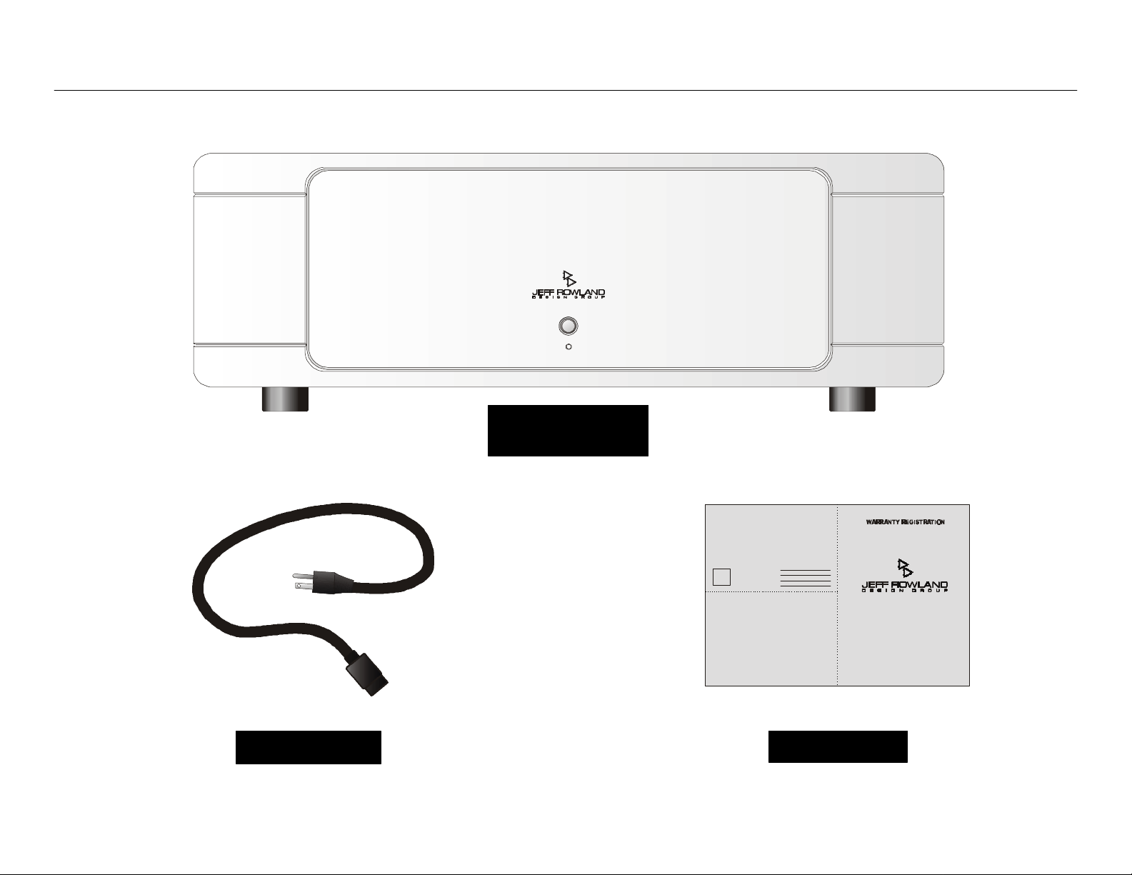
ContentsContents
Model 112 Stereo Model 112 Stereo
WarraWarranty Cardnty Card
AC Power CableAC Power Cable
Power AmplifierPower Amplifier

Initial InspectionInitial Inspection
ContentsContents
ContentsContents
IInspect the shipping container for damage. If the shipping
container, packing material, amplifier, or accessories are damaged
or missing, notify your dealer and the shipper (if a claim is to be
made) immediately. Note:Note: Many shippers require notification and
inspection within twenty-four hours of delivery to determine the
nature of damages incurred.
Your Model 112 Stereo Power Amplifier has undergone extensive
performance evaluations, listening tests, quality control inspections,
and a minimum seventy-two hour burn-in period prior to shipment
and should therefore be in perfect operating condition upon receipt.
If the amplifier does not operate correctly, please notify your dealer
immediately.
We strongly suggest that you save all packing materials. If the
amplifier is to be returned to your dealer or Jeff Rowland Design
Group, the original packing materials must be used for shipment to
avoid damage. Neither Jeff Rowland Design Group nor the shipper
can be held responsible for damages incurred during transit if the
original factory packing is not used. All factory returns require that
Jeff Rowland Design Group issue a Return Authorization (RA) number
prior to shipment.
EEnsure that all of the auxiliary components listed below are enclosed
within the accessory box. Refer to the diagrams illustrated above
and verify the components included.
11 One AC Power Cable
22 One Warranty Card (In some countries, warranties are provided
by the respective importer.)
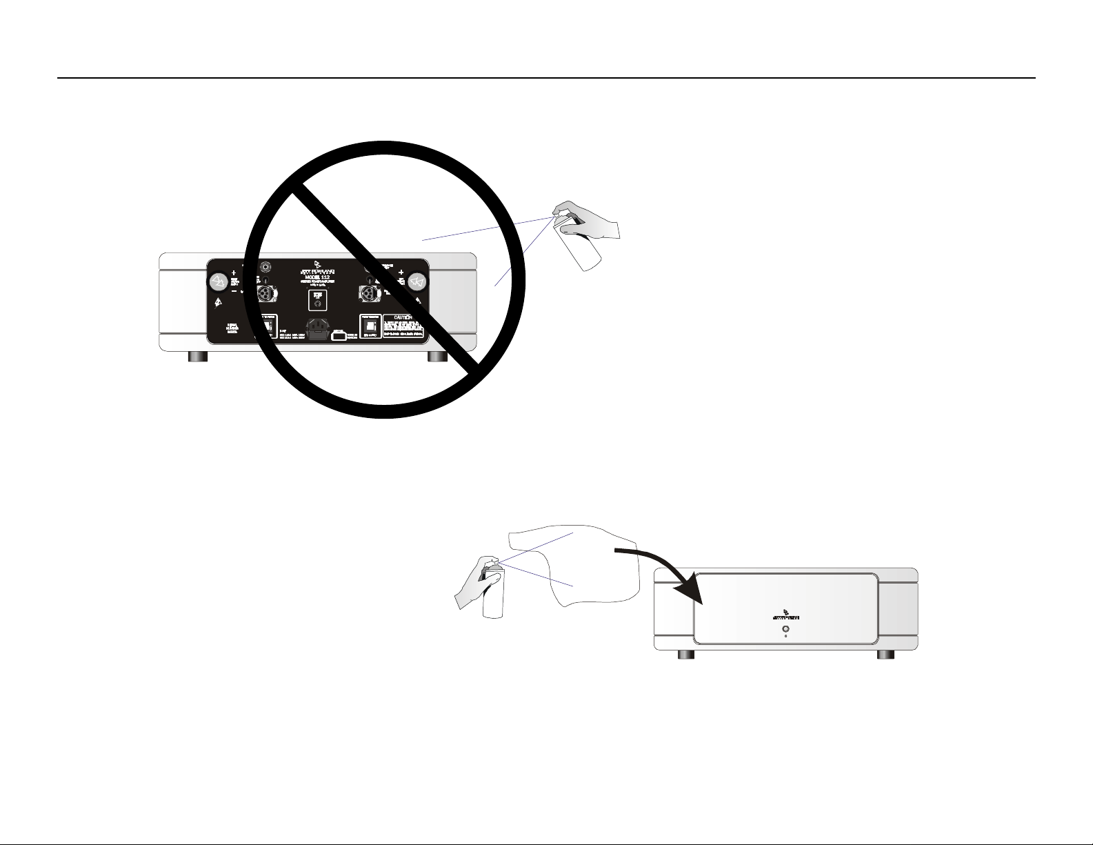
Care, Cleaning, and MaintenanceCare, Cleaning, and Maintenance
NEUTRIK
PUSH
NEUTRIK
PUSH
 Loading...