

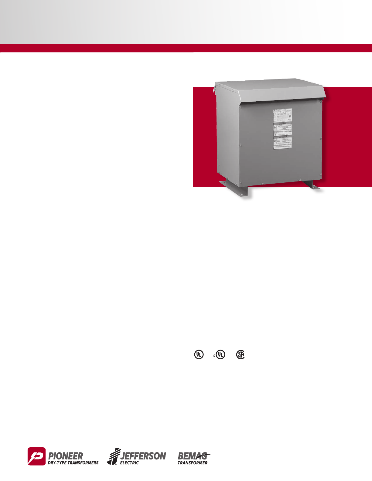
Single-Phase Ventilated
15 to 1,650 kVA
Applications
n For general loads, including lighting, industrial and
commercial applications
Specications
n Meets DOE-2016 and C802 standards for energy
efciency
n 60 Hz operation
n Aluminum windings
n 150ºC temperature rise
n 220ºC insulation class standard
n NEMA3R rated enclosures standard
n Heat-cured ASA-61 gray powder coat nish
n Cores of high quality electrical steel
n Primary taps on most units
n Lugs provided for units up to and including 50 kVA on
catalog items
Standards
nMeets DOE-2016 standard Part 431, Subpart K for
energy efciency
nMeets NRCAN 2019 requirements, C802.2.18 Standard
for energy efciency
n Built in accordance with NEMA, ANSI, UL and CSA
standards
1
Features, Functions, Benets
n Large connection compartment for ease of wiring and
installation
n Many sizes in stock and available for immediate
shipment
n Quiet operation for installation exibility
n Seismic certication for all units through 250 kVA
Options and Accessories
n Other sizes, voltages and temperature rises available
n Copper windings
n CE Marked units available as custom
n Wall brackets available for units up to 75 kVA
Approvals
1-1
1-2
Single-Phase Ventilated
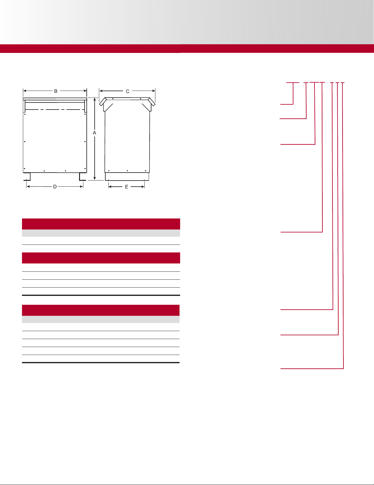
Enclosure Figure
Figure 24
Wall Mounting Bracket Kits
Part Number Description Max Unit Wgt (lbs)
223-7008-030 For 15 kVA units, 150°C rise 250
223-7008-075 For 16 to 75 kVA units, 150°C rise 750
Wall Mounting Bracket Kits with Drip Pans
400-4701-222
400-4701-223
400-4701-224
400-4701-225
For Single Phase units, 15” width
For Single Phase units, 17” width
For Single Phase units, 20” width
For Single Phase units, 22” width
250
750
750
750
Model Numbers Dened
Single-Phase, Ventilated
Floor Mount
Type
C802 compliant 5
DOE compliant 9
kVA Rating / XX kVA Rating / XX
15 16 112.5 25
20 17 150 26
25 18 167 27
30 19 200 28
37.5 20 225 29
45 21 250 30
50 22 300 31
75 23 333 32
100 24
Up to 1,650 kVA available as specials
Primary Secondary
120x240 120/240 1
208 120/240 2
Custom 3
277 120/240 4
240x480 120/240 5
Specials* 6
120x240 120/240 7
600 120/240 8
Custom 9
J
421-TXXY-ABC
Lugs
Part Number kVA Primary Lug Qty Secondary Lug Qty
4PT-2007-LUG 15 #14 - 2 2 #2/0 - 6 2
4PT-2017-LUG 25 #14 - 2 2 250MCM - 6 2
4PT-2008-LUG 37.5 #14 - 2 2 350MCM - 6 2
4PT-2009-LUG 50 #2/0 - 6 2 600MCM - 6 2
4PT-2018-LUG† 75 #2/0 - 6 2 600MCM - 6 4
† Must be ordered, not included on stock units
Wiring
Aluminum 0
Copper 8
Temperature Rise
150°C 0
115°C 1
80° 8
No shield 0
Shield 5
J
*Sufx dened incrementally
Not all features listed are compatible
Shield

Single-Phase General Purpose Transformers – DOE Compliant
150°C Temperature Rise • Aluminum Windings • NEMA3R Enclosures
Taps: 2 @ 2.5% FCAN & 4 @ 2.5% FCBN
240 x 480V — 120/240V
kVA Catalog Number
15 421-9165-000 24 27 15 20.5 12.5 11 190 S480F 223-7008-030
25 421-9185-000 24 29 17 22.5 14 13 265 S480F 223-7008-075
37.5 421-9205-000 24 31 20 23.5 16.9 14 330 S480F 223-7008-075
50 421-9225-000 24 32 22 25.5 19 16 465 S480F 223-7008-075
75 421-9235-000 24 34 22 27.5 19 16 555 S480F 223-7008-075
100 421-9245-000 24 36 22 29.5 19 18 690 S480F n/a
150 421-9265-000 24 55 34 37 31 25 1255 S480F n/a
167 421-9275-000 24 55 34 37 31 25 1300 S480F n/a
200 421-9285-000 24 52 35 37 31.5 25 1355 S480F n/a
250 421-9305-000 24 55 39 44 31.5 25 1690 S480F n/a
300 421-9315-000 24 TBD TBD TBD TBD TBD TBD S480F n/a
333 421-9325-000 24 TBD TBD TBD TBD TBD TBD S480F n/a
Enclosure
Figure
150°C Temperature Rise • Aluminum Windings • NEMA3R Enclosures
Taps: 2 @ 2.5% FCAN & 2 @ 2.5% FCBN
600V — 120/240V
15 421-9168-000 24 27 15 20.5 12.5 11 190 S600E 223-7008-030
25 421-9188-000 24 29 17 22.5 14 13 265 S600E 223-7008-075
37.5 421-9208-000 24 31 20 23.5 16.9 14 330 S600E 223-7008-075
50 421-9228-000 24 32 22 25.5 19 16 405 S600E 223-7008-075
75 421-9238-000 24 34 22 27.5 19 16 620 S600E 223-7008-075
100 421-9248-000 24 36 22 29.5 19 18 725 S600E n/a
150 421-9268-000 24 55 34 37 31 25 1255 S600E n/a
167 421-9278-000 24 55 34 37 31 25 1300 S600E n/a
200 421-9288-000 24 52 35 37 31.5 25 1355 S600E n/a
250 421-9308-000 24 55 39 44 31.5 25 1690 S600E n/a
300 421-9318-000 24 TBD TBD TBD TBD TBD TBD S600E n/a
333 421-9328-000 24 TBD TBD TBD TBD TBD TBD S600E n/a
Height (A)
inches
Width (B)
inches
Depth (C)
inches
(D)
inches
(E)
inches
Est Ship
Wgt
Wiring
Diagram
Wall Mounting
Bracket Kit
1-3Single-Phase Ventilated
Housing dimensions subject to change without notice.
1-4
Single-Phase Ventilated
Single-Phase General Purpose Transformers – NRCAN-2019, C802 Compliant
150°C Temperature Rise • Aluminum Windings • NEMA3R Enclosures
Taps: 2 @ 2.5% FCAN & 4 @ 2.5% FCBN
240 x 480V — 120/240V
kVA Catalog Number
15 421-5165-000 24 27 15 20.5 12.5 11 190 S480F 223-7008-030
25 421-5185-000 24 29 17 22.5 14 13 265 S480F 223-7008-075
37.5 421-5205-000 24 31 20 23.5 16.9 14 330 S480F 223-7008-075
50 421-5225-000 24 32 22 25.5 19 16 405 S480F 223-7008-075
75 421-5235-000 24 34 22 27.5 19 16 620 S480F 223-7008-075
100 421-5245-000 24 36 22 29.5 19 18 725 S480F n/a
150 421-5265-000 24 55 34 37 31 25 1255 S480F n/a
167 421-5275-000 24 55 34 37 31 25 1300 S480F n/a
200 421-5285-000 24 52 35 37 31.5 25 1355 S480F n/a
250 421-5305-000 24 55 39 44 31.5 25 1690 S480F n/a
300 421-5315-000 24 TBD TBD TBD TBD TBD TBD S480F n/a
333 421-5325-000 24 TBD TBD TBD TBD TBD TBD S480F n/a
Enclosure
Figure
150°C Temperature Rise • Aluminum Windings • NEMA3R Enclosures
Taps: 2 @ 2.5% FCAN & 2 @ 2.5% FCBN
600V — 120/240V
15 421-5168-000 24 27 15 20.5 12.5 11 190 S600E 223-7008-030
25 421-5188-000 24 29 17 22.5 14 13 265 S600E 223-7008-075
37.5 421-5208-000 24 31 20 23.5 16.9 14 330 S600E 223-7008-075
50 421-5228-000 24 32 22 25.5 19 16 405 S600E 223-7008-075
75 421-5238-000 24 34 22 27.5 19 16 620 S600E 223-7008-075
100 421-5248-000 24 36 22 29.5 19 18 725 S600E n/a
150 421-5268-000 24 55 34 37 31 25 1255 S600E n/a
167 421-5278-000 24 55 34 37 31 25 1300 S600E n/a
200 421-5288-000 24 52 35 37 31.5 25 1355 S600E n/a
250 421-5308-000 24 55 39 44 31.5 25 1690 S600E n/a
300 421-5318-000 24 TBD TBD TBD TBD TBD TBD S600E n/a
333 421-5328-000 24 TBD TBD TBD TBD TBD TBD S600E n/a
Height (A)
inches
Width (B)
inches
Depth (C)
inches
(D)
inches
(E)
inches
Est Ship
Wgt
Wiring
Diagram
Wall Mounting
Bracket Kit
Housing dimensions subject to change without notice.
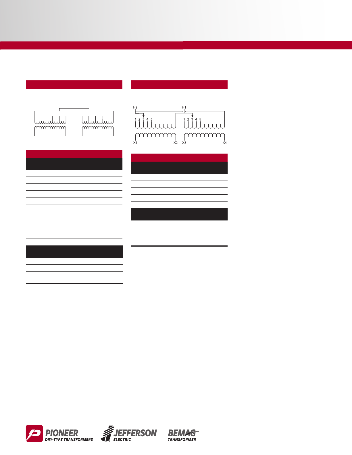
Wiring Diagrams
H1
H2
1-5Single-Phase Ventilated
S480F Wiring Diagram & Connections
Wiring Diagram
Primary: 240 x 480 Volts
Secondary: 120/240 Volts
PRIMARY
3
7
X1
1
5
X2
SECONDARY
Connections
Primary Jumpers Between Taps Primary Lines
Volts Left Coil Right Coil Connect To
504 1 2 H1, H2
492 3 2 H1, H2
480 3 4 H1, H2
468 5 4 H1, H2
456 5 6 H1, H2
444 7 6 H1, H2
432 7 8 H1, H2
252 H2, 1 H1, 2 H1, H2
240 H2, 3 H1, 4 H1, H2
228 H2, 5 H1, 6 H1, H2
216 H2, 7 H1, 8 H1, H2
Secondary Volts
240 X2 to X3 X1, X4
120/240 X2 to X3 X1, X2, X4
120
Interconnect
X1 to X3
X2 to X4
4
2
X3
Secondary Lines
6
8
Connect To
X1, X4
X4
S600E Wiring Diagram & Connections
Wiring Diagram
Primary: 600 Volts
Secondary: 120/240 Volts
PRIMARY
SECONDARY
Connections
Primary Volts
630 1 H1, H2
615 2 H1, H2
600 3 H1, H2
585 4 H1, H2
570 5 H1, H2
Secondary Volts
240 X2 to X3 X1, X4
120/240 X2 to X3 X1, X2, X4
120
On Each Coil
Jumper Taps To
Interconnect
X1 to X3
X2 to X4
Primary Lines
Connect To
Secondary Lines
Connect To
X1, X4
 Loading...