

Page 1

INSTRUMENT PANEL SYSTEMS
CONTENTS
page page
DESCRIPTION AND OPERATION
CIGAR LIGHTER RELAY ................... 4
INSTRUMENT CLUSTER ................... 2
INSTRUMENT PANEL ..................... 1
INSTRUMENT PANEL CIGAR LIGHTER ....... 3
INSTRUMENT PANEL POWER OUTLET ....... 4
INSTRUMENT PANEL SYSTEM ............. 1
DIAGNOSIS AND TESTING
CIGAR LIGHTER RELAY .................. 12
INSTRUMENT CLUSTER ................... 5
INSTRUMENT PANEL CIGAR LIGHTER ...... 11
INSTRUMENT PANEL POWER OUTLET ...... 12
REMOVAL AND INSTALLATION
CIGAR LIGHTER RELAY .................. 15
CLUSTER BEZEL ........................ 16
GLOVE BOX ........................... 22
GLOVE BOX COMPONENTS ............... 22
GLOVE BOX LATCH STRIKER ............. 24
HEADLAMP SWITCH .................... 17
INSTRUMENT CLUSTER .................. 18
INSTRUMENT CLUSTER COMPONENTS ..... 18
INSTRUMENT PANEL ACCESSORY SWITCH
BEZEL .............................. 15
INSTRUMENT PANEL ASSEMBLY .......... 26
INSTRUMENT PANEL CENTER BEZEL ....... 14
INSTRUMENT PANEL CENTER SUPPORT
BRACKET ............................ 25
INSTRUMENT PANEL END CAP ............ 24
INSTRUMENT PANEL TOP COVER .......... 21
KNEE BLOCKER ........................ 13
STEERING COLUMN OPENING COVER ...... 13
DESCRIPTION AND OPERATION
INSTRUMENT PANEL SYSTEM
DESCRIPTION
The instrument panel serves as the command center of the vehicle, which necessarily makes it a very
complex unit. The instrument panel is designed to
house the controls and monitors for standard and
optional powertrains, climate control systems, audio
systems, lighting systems, safety systems and many
other comfort or convenience items. The instrument
panel is also designed so that all of the various controls can be safely reached and the monitors can be
easily viewed by the vehicle operator when driving,
while still allowing relative ease of access to each of
these items for service. See the owner’s manual in
the vehicle glove box for more information on the features, use and operation of all of the instrument
panel components and systems.
This group is responsible for covering service information for the vehicle instrument panel systems.
However, complete service information coverage for
all of the systems and components housed in the
instrument panel in a single section of the service
manual would not be practical. Therefore, the service
information for any component will be found in the
group designated to cover the vehicle system that the
component belongs to, even though the component is
mounted on or in the instrument panel. If you cannot
locate a listing for the component or system you are
servicing in the table of contents for this group, or if
you are uncertain as to which vehicle system a component belongs to, it is suggested that you refer to
the alphabetical Component and System Index
found at the back of this service manual.
NOTE: This group covers both Left-Hand Drive
(LHD) and Right-Hand Drive (RHD) versions of this
model. Whenever required and feasible, the RHD
versions of affected vehicle components have been
constructed as mirror-image of the LHD versions.
While most of the illustrations used in this group
represent only the LHD version, the diagnostic and
service procedures outlined can generally be
applied to either version. Exceptions to this rule
have been clearly identified as LHD or RHD, if a
special illustration or procedure is required.
INSTRUMENT PANEL
DESCRIPTION
This instrument panel uses a full-width structural
plastic foundation as its primary support. When the
two primary molded plastic components of this structure are vibration welded together they provide superior instrument panel stiffness and integrity to help
XJ INSTRUMENT PANEL SYSTEMS 8E - 1
Page 2

reduce buzzes, squeaks, and rattles even on the
bumpiest roads.
This type of construction also provides improved
energy absorption which, in conjunction with the
dual airbag modules and seat belts, helps to improve
occupant protection. This foundation structure also
serves as the air duct for the heating and air conditioning system panel outlets, which greatly reduces
the number of components used over conventional
instrument panel construction.
Modular instrument panel construction allows all
of the gauges and controls to be serviced from the
front of the panel. In addition, most of the instrument panel electrical components can be accessed
without complete instrument panel removal. If necessary, the instrument panel can be removed from the
vehicle as an assembly.
Removal of the steering column opening cover and
knee blocker provides access to the steering column
mounts, the steering column wiring, the headlamp
switch, the electronic combination flasher, and much
of the instrument panel wiring. Removal of the glove
box provides access to the heating and air conditioning electrical and vacuum harnesses, the blower
motor relay, the radio antenna coaxial cable, the
lower passenger side airbag mounts, and additional
instrument panel wiring.
Removal of the instrument panel center bezel
allows access to the radio, the heating and air conditioning controls, the accessory switches, the cigar
lighter, and the accessory power outlet. Removal of
the instrument cluster bezel allows access to the
instrument cluster. Removal of the cluster assembly
allows access to the cluster illumination and indicator lamp bulbs, and more of the instrument panel
wiring.
Removal of the instrument panel top cover allows
access to the upper passenger side airbag mounts.
Instrument panel removal is required for service of
most internal components of the heating and air conditioning system housing.
INSTRUMENT CLUSTER
DESCRIPTION
Two basic instrument clusters are offered on this
model: low-line, or high-line. Both clusters are electromechanical units that utilize integrated circuitry
and information carried on the Chrysler Collision
Detection (CCD) data bus network for control of all
gauges and many of the indicator lamps. These clusters also incorporate a digital Vacuum Fluorescent
Display (VFD) for the odometer/trip odometer display
functions. Some variations of each cluster exist due
to optional equipment and regulatory requirements.
The low-line cluster includes the following analog
gauges:
• Fuel gauge
• Speedometer.
This cluster also includes provisions for the follow-
ing indicator lamps:
• Airbag indicator lamp
• Anti-lock brake system lamp
• Brake warning lamp
• Coolant temperature warning lamp
• Cruise-on indicator lamp
• Four-wheel drive (Part Time and/or Full Time)
indicator lamps
• Headlamp high beam indicator lamp
• Low oil pressure warning lamp
• Low washer fluid warning lamp
• Malfunction indicator (Check Engine) lamp
• Seat belt reminder lamp
• Sentry Key Immobilizer System (SKIS) indicator
lamp
• Turn signal indicator lamps
• Upshift indicator lamp (manual transmission)
• Voltage warning lamp.
The high-line cluster replaces some of the indicator
lamps found in the low-line cluster with analog
gauges. The high-line cluster includes the following
analog gauges:
• Coolant temperature gauge
• Fuel gauge
• Oil pressure gauge
• Speedometer
• Tachometer
• Voltmeter.
The high-line cluster also adds a check gauges
lamp and a low fuel warning lamp to the remaining
indicator lamps found in the low-line cluster.
Both instrument clusters feature circuitry that has
a self-diagnostic actuator test capability, which will
test each of the CCD bus message-controlled functions of the cluster by lighting the appropriate indicator lamps and positioning the gauge needles at
several predetermined locations on the gauge faces in
a prescribed sequence. For more information on this
function, refer to Instrument Cluster in the Diagnosis and Testing section of this group.
The instrument cluster circuitry also integrates a
chime tone generator and a timer circuit. These
items replace the chime or buzzer module, and the
separate timer circuit for the rear window defogger
system. Refer to Chime Warning System in the
Description and Operation section of Group 8U Chime/Buzzer Warning Systems for more information
on the chime functions of the instrument cluster.
Refer to Rear Window Defogger System in the
Description and Operation section of Group 8N -
8E - 2 INSTRUMENT PANEL SYSTEMS XJ
DESCRIPTION AND OPERATION (Continued)
Page 3

Electrically Heated Systems for more information on
the timer function of the instrument cluster.
The instrument clusters for this model are serviced
only as complete units. If a cluster gauge or the cluster circuit board are faulty, the entire cluster must be
replaced. The cluster lens, the cluster hood and
mask, the rear cluster housing cover, the odometer
reset knob boot and the incandescent lamp bulbs and
holders are available for service replacement.
OPERATION
GAUGE
With the ignition switch in the On or Start positions, voltage is supplied to all gauges through the
instrument cluster electronic circuit board. With the
ignition switch in the Off position, voltage is not supplied to the gauges. The gauges do not accurately
indicate any vehicle condition unless the ignition
switch is in the On or Start positions.
All of the instrument cluster gauges, except the
odometer, are air core magnetic units. Two fixed electromagnetic coils are located within the gauge. These
coils are wrapped at right angles to each other
around a movable permanent magnet. The movable
magnet is suspended within the coils on one end of a
shaft. The gauge needle is attached to the other end
of the shaft.
One of the coils has a fixed current flowing
through it to maintain a constant magnetic field
strength. Current flow through the second coil
changes, which causes changes in its magnetic field
strength. The current flowing through the second coil
is changed by the instrument cluster electronic circuitry in response to messages received on the
Chrysler Collision Detection (CCD) data bus network.
The gauge needle moves as the movable permanent
magnet aligns itself to the changing magnetic fields
created around it by the electromagnets. The instrument cluster circuitry is programmed to move all of
the gauge needles back to the low end of their respective scales after the ignition switch is turned to the
Off position.
INDICATOR LAMP
Indicator lamps are located in the instrument cluster and are served by the cluster circuit board and
connectors. Many of the indicator lamps in the
instrument cluster are controlled by the instrument
cluster circuitry in response to messages received
over the Chrysler Collision Detection (CCD) data bus
network.
The anti-lock brake system lamp, brake warning
lamp, four-wheel drive indicator lamps, headlamp
high beam indicator lamp, low washer fluid warning
lamp and turn signal indicator lamps are hard wired.
The seat belt reminder lamp is controlled by the
instrument cluster programming. The instrument
cluster circuitry uses CCD data bus messages from
the Powertrain Control Module (PCM), Airbag Control Module (ACM), and the Sentry Key Immobilizer
Module (SKIM) to control all of the remaining indicator lamps.
Each of the indicator lamps in the instrument cluster uses incandescent bulbs and holders, which are
available for service replacement.
CLUSTER ILLUMINATION LAMP
The cluster illumination lamps are hard wired in
the instrument cluster. When the park or head lamps
are turned on, the cluster illumination lamps light.
Illumination brightness is adjusted by rotating the
headlamp switch knob (clockwise to dim, counterclockwise to brighten). The instrument cluster illumination lamps receive battery feed from the panel
dimmer rheostat in the headlamp switch through a
fuse in the fuseblock module.
The instrument cluster electronic circuitry also
monitors the cluster illumination lamp dimming level
whenever the park or head lamps are turned on. The
instrument cluster electronic circuitry responds by
adjusting the dimming level of the odometer Vacuum
Fluorescent Display (VFD), and sending dimming
level messages over the Chrysler Collision Detection
(CCD) data bus network. When the park lamps or
headlamps are turned off, the VFD is illuminated at
full brightness for improved daylight visibility.
Each of the cluster illumination lamps is located on
the instrument cluster circuit board. Each cluster
illumination lamp has a replaceable bulb and bulb
holder.
INSTRUMENT PANEL CIGAR LIGHTER
DESCRIPTION
A cigar lighter is standard equipment on this
model. The cigar lighter is installed in the instrument panel accessory switch bezel, which is located
near the bottom of the instrument panel center bezel
area, below the heater and air conditioner controls.
The cigar lighter base is secured by a snap fit within
the accessory switch bezel.
The cigar lighter receptacle is serviced only as a
part of the accessory switch bezel unit. If the cigar
lighter base is faulty or damaged, the accessory
switch bezel unit must be replaced. The cigar lighter
knob and heating element unit is available for service. This component cannot be repaired and, if
faulty or damaged, it must be replaced.
XJ INSTRUMENT PANEL SYSTEMS 8E - 3
DESCRIPTION AND OPERATION (Continued)
Page 4

OPERATION
The cigar lighter consists of two major components:
a knob and heating element unit, and the cigar
lighter base or receptacle shell. The receptacle shell
is connected to ground, and an insulated contact in
the bottom of the shell is connected to battery current. The cigar lighter receives battery voltage from a
fuse in the junction block through the cigar lighter
relay only when the ignition switch is in the Accessory or On positions. Refer to Cigar Lighter Relay
in the Description and Operation section of this
group for more information on this component.
The cigar lighter knob and heating element are
encased within a spring-loaded housing, which also
features a sliding protective heat shield. When the
knob and heating element are inserted in the receptacle shell, the heating element resistor coil is
grounded through its housing to the receptacle shell.
If the cigar lighter knob is pushed inward, the heat
shield slides up toward the knob exposing the heating element, and the heating element extends from
the housing toward the insulated contact in the bottom of the receptacle shell.
Two small spring-clip retainers are located on
either side of the insulated contact inside the bottom
of the receptacle shell. These clips engage and hold
the heating element against the insulated contact
long enough for the resistor coil to heat up. When the
heating element is engaged with the contact, battery
current can flow through the resistor coil to ground,
causing the resistor coil to heat.
When the resistor coil becomes sufficiently heated,
excess heat radiates from the heating element causing the spring-clips to expand. Once the spring-clips
expand far enough to release the heating element,
the spring-loaded housing forces the knob and heating element to pop back outward to their relaxed
position. When the cigar lighter knob and element
are pulled out of the receptacle shell, the protective
heat shield slides downward on the housing so that
the heating element is recessed and shielded around
its circumference for safety.
CIGAR LIGHTER RELAY
DESCRIPTION
The cigar lighter relay is an electromechanical
device that switches fused battery current to the
cigar lighter when the ignition switch is turned to
the Accessory or On positions. The cigar lighter relay
is located in the junction block, on the right cowl side
panel below the instrument panel in the passenger
compartment.
The cigar lighter relay is a International Standards
Organization (ISO) relay. Relays conforming to the
ISO specifications have common physical dimensions,
current capacities, terminal patterns, and terminal
functions.
The cigar lighter relay cannot be repaired or
adjusted and, if faulty or damaged, it must be
replaced.
OPERATION
The ISO relay consists of an electromagnetic coil, a
resistor or diode, and three (two fixed and one movable) electrical contacts. The movable (common feed)
relay contact is held against one of the fixed contacts
(normally closed) by spring pressure. When the electromagnetic coil is energized, it draws the movable
contact away from the normally closed fixed contact,
and holds it against the other (normally open) fixed
contact.
When the electromagnetic coil is de-energized,
spring pressure returns the movable contact to the
normally closed position. The resistor or diode is connected in parallel with the electromagnetic coil in the
relay, and helps to dissipate voltage spikes that are
produced when the coil is de-energized.
INSTRUMENT PANEL POWER OUTLET
DESCRIPTION
An accessory power outlet is standard equipment
on this model. The power outlet is installed in the
instrument panel accessory switch bezel, which is
located near the bottom of the instrument panel center bezel area, below the heater and air conditioner
controls. The power outlet base is secured by a snap
fit within the accessory switch bezel. A plastic protective cap snaps into the power outlet base when the
power outlet is not being used, and hangs from the
power outlet base mount by an integral bail strap
while the power outlet is in use.
The power outlet receptacle unit and the accessory
power outlet protective cap are serviced only as a
part of the accessory switch bezel unit. If the power
outlet base is faulty or damaged, the entire accessory
switch bezel unit must be replaced.
OPERATION
The power outlet base or receptacle shell is connected to ground, and an insulated contact in the
bottom of the shell is connected to battery current.
The power outlet receives battery voltage from a fuse
in the junction block at all times.
While the power outlet is very similar to a cigar
lighter base unit, it does not include the two small
spring-clip retainers inside the bottom of the receptacle shell that are used to secure the cigar lighter
heating element to the insulated contact.
8E - 4 INSTRUMENT PANEL SYSTEMS XJ
DESCRIPTION AND OPERATION (Continued)
Page 5

DIAGNOSIS AND TESTING
INSTRUMENT CLUSTER
If all of the gauges and/or indicator lamps are inoperative, perform the Preliminary Diagnosis. If an
individual gauge or Chrysler Collision Detection
(CCD) data bus message-controlled indicator lamp is
inoperative, go directly to the Actuator Test. If an
individual hard wired indicator lamp is inoperative,
refer to Instrument Cluster - Hard Wired Lamp
Diagnosis in the Diagnosis and Testing section of
this group for the procedures to diagnosis that lamp.
For complete circuit diagrams, refer to Instrument
Cluster in the Contents of Group 8W - Wiring Diagrams.
WARNING: ON VEHICLES EQUIPPED WITH AIRBAGS, REFER TO GROUP 8M - PASSIVE
RESTRAINT SYSTEMS BEFORE ATTEMPTING ANY
STEERING WHEEL, STEERING COLUMN, OR
INSTRUMENT PANEL COMPONENT DIAGNOSIS OR
SERVICE. FAILURE TO TAKE THE PROPER PRECAUTIONS COULD RESULT IN ACCIDENTAL AIRBAG DEPLOYMENT AND POSSIBLE PERSONAL
INJURY.
PRELIMINARY DIAGNOSIS
(1) If the indicator lamps operate, but none of the
gauges operate, go to Step 2. If all of the gauges and
the data bus message-controlled indicator lamps are
inoperative, go to Step 5.
(2) Check the fused B(+) fuse in the Power Distribution Center (PDC). If OK, go to Step 3. If not OK,
repair the shorted circuit or component as required
and replace the faulty fuse.
(3) Check for battery voltage at the fused B(+) fuse
in the PDC. If OK, go to Step 4. If not OK, repair the
open fused B(+) circuit to the battery as required.
(4) Disconnect and isolate the battery negative
cable. Remove the instrument cluster. Connect the
battery negative cable. Check for battery voltage at
the fused B(+) circuit cavity of the instrument cluster
wire harness connector A. If OK, refer to Instru-
ment Cluster - Actuator Test in the Diagnosis and
Testing section of this group. If not OK, repair the
open fused B(+) circuit to the fuse in the PDC as
required.
(5) Check the fused ignition switch output (run/
start) fuse in the junction block. If OK, go to Step 6.
If not OK, repair the shorted circuit or component as
required and replace the faulty fuse.
(6) Turn the ignition switch to the On position and
check for battery voltage at the fused ignition switch
output (run/start) fuse in the junction block. If OK,
go to Step 7. If not OK, repair the open fused ignition
switch output (run/start) circuit to the ignition switch
as required.
(7) Turn the ignition switch to the Off position.
Disconnect and isolate the battery negative cable.
Install the instrument cluster. Connect the battery
negative cable. Turn the ignition switch to the On
position. Set the park brake. The red brake warning
lamp should light. If OK, go to Step 8. If not OK, go
to Step 9.
(8) Turn the ignition switch to the Off position.
Turn on the park lamps and adjust the panel lamps
dimmer rheostat in the headlamp switch to the full
bright position. The cluster illumination lamps
should light. If OK, refer to Instrument Cluster -
Actuator Test in the Diagnosis and Testing section
of this group. If not OK, go to Step 10.
(9) Turn the ignition switch to the Off position.
Disconnect and isolate the battery negative cable.
Remove the instrument cluster. Connect the battery
negative cable. Turn the ignition switch to the On
position. Check for battery voltage at the fused ignition switch output (run/start) circuit cavity of the
instrument cluster wire harness connector A. If OK,
refer to Instrument Cluster - Actuator Test in the
Diagnosis and Testing section of this group. If not
OK, repair the open fused ignition switch output
(run/start) circuit to the fuse in the junction block as
required.
(10) Disconnect and isolate the battery negative
cable. Remove the instrument cluster. Check for continuity between the ground circuit cavity of the
instrument cluster wire harness connector A and a
good ground. There should be continuity. If OK, refer
to Instrument Cluster - Actuator Test in the
Diagnosis and Testing section of this group. If not
OK, repair the open ground circuit to ground as
required.
ACTUATOR TEST
The instrument cluster actuator test will put the
instrument cluster into its self-diagnostic mode. In
this mode the instrument cluster can perform a selfdiagnostic test that will confirm that the instrument
cluster circuitry, the gauges, and the CCD data bus
message controlled indicator lamps are capable of
operating as designed. During the actuator test the
instrument cluster circuitry will position each of the
gauge needles at various specified calibration points,
and turn all of the CCD data bus message-controlled
lamps on and off at specified time intervals (Fig. 1)
or (Fig. 2).
Successful completion of the actuator test will confirm that the instrument cluster is operational. However, there may still be a problem with the CCD data
bus, the Powertrain Control Module (PCM), the Airbag Control Module (ACM), the Sentry Key Immobi-
XJ INSTRUMENT PANEL SYSTEMS 8E - 5
Page 6

lizer Module (SKIM) or the inputs to one of these
electronic control modules. Use a DRB scan tool and
the proper Diagnostic Procedures manual for testing
of these components.
If an individual gauge does not respond properly,
or does not respond at all during the actuator test,
the instrument cluster should be removed. However,
check that the gauge mounting screws on the instrument cluster electronic circuit board for proper tightness before considering instrument cluster
replacement. If the gauge mounting screws check
OK, replace the faulty cluster.
If an individual indicator lamp does not illuminate
during the actuator test, the instrument cluster
should be removed. However, check that the incandescent lamp bulb is not faulty and that the bulb
holder is properly installed on the instrument cluster
electronic circuit board before considering instrument
cluster replacement. If the bulb and bulb holder
check OK, replace the faulty instrument cluster.
(1) Begin the test with the ignition switch in the
Off position.
(2) Depress the trip odometer reset button.
(3) While holding the trip odometer reset button
depressed, turn the ignition switch to the On position, but do not start the engine.
(4) Release the trip odometer reset button.
(5) Compare the operation of the suspect gauge(s)
and/or indicator lamp(s) with the Instrument Cluster
Actuator Test chart (Fig. 1) or (Fig. 2).
(6) The instrument cluster will automatically exit
the self-diagnostic mode and return to normal operation at the completion of the test, if the ignition
switch is turned to the Off position during the test,
or if a vehicle speed message indicating that the
vehicle is moving is received from the PCM on the
CCD data bus during the test.
(7) Go back to Step 1 to repeat the test, if
required.
HARD WIRED LAMP DIAGNOSIS
Each of the lamps found in this section depends
upon a hard wired circuit input to the instrument
cluster for proper operation. The following procedures
will help to diagnose conditions that may cause an
inoperative hard wired lamp circuit condition.
WARNING: ON VEHICLES EQUIPPED WITH AIRBAGS, REFER TO GROUP 8M - PASSIVE
RESTRAINT SYSTEMS BEFORE ATTEMPTING ANY
STEERING WHEEL, STEERING COLUMN, OR
INSTRUMENT PANEL COMPONENT DIAGNOSIS OR
SERVICE. FAILURE TO TAKE THE PROPER PRECAUTIONS COULD RESULT IN ACCIDENTAL AIRBAG DEPLOYMENT AND POSSIBLE PERSONAL
INJURY.
ANTI-LOCK BRAKE SYSTEM LAMP
The diagnosis found here addresses an inoperative
Anti-lock Brake System (ABS) lamp condition. If the
ABS lamp stays on with the ignition switch in the
On position, or comes on and stays on while driving,
refer to Antilock Brakes in the Diagnosis and Testing section of Group 5 - Brakes for diagnosis. If no
ABS problem is found, the following procedure will
help locate a short or open in the ABS lamp circuit.
For complete circuit descriptions, refer to Instru-
ment Cluster in the Contents of Group 8W - Wiring
Diagrams.
(1) Check the fused ignition switch output (run/
start) fuse in the junction block. If OK, go to Step 2.
If not OK, repair the shorted circuit or component as
required and replace the faulty fuse.
(2) Turn the ignition switch to the On position.
Check for battery voltage at the fused ignition switch
output (run/start) fuse in the junction block. If OK,
go to Step 3. If not OK, repair the open fused ignition
switch output (run/start) circuit to the ignition switch
as required.
(3) Turn the ignition switch to the Off position.
Disconnect and isolate the battery negative cable.
Remove the instrument cluster. Connect the battery
negative cable. Turn the ignition switch to the On
position and within five seconds check for continuity
between the ABS warning indicator driver circuit
cavity of the instrument cluster wire harness connector A and a good ground. There should be continuity
for five seconds after ignition On, and then an open
circuit. If OK, replace the faulty bulb. If not OK, go
to Step 4.
(4) Turn the ignition switch to the Off position.
Disconnect and isolate the battery negative cable.
Disconnect the Controller Anti-lock Brake (CAB) wire
harness connector. Check for continuity between the
ABS warning indicator driver circuit cavity of the
instrument cluster wire harness connector A and a
good ground. There should be no continuity. If OK, go
to Step 5. If not OK, repair the shorted ABS warning
indicator driver circuit as required.
(5) Check for continuity between the ABS warning
indicator driver circuit cavities of the instrument
cluster wire harness connector A and the CAB wire
harness connector. There should be continuity. If OK,
refer to Antilock Brakes in the Diagnosis and Testing section of Group 5 - Brakes for diagnosis of the
CAB. If not OK, repair the open ABS warning indicator driver circuit as required.
BRAKE WARNING LAMP
The diagnosis found here addresses an inoperative
brake warning lamp condition. If the brake warning
lamp stays on with the ignition switch in the On
position and the park brake released, or comes on
8E - 6 INSTRUMENT PANEL SYSTEMS XJ
DIAGNOSIS AND TESTING (Continued)
Page 7
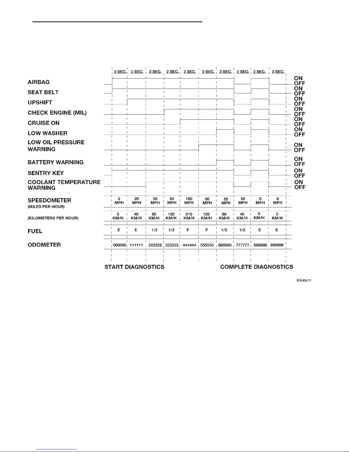
Fig. 1 Low-Line Instrument Cluster Actuator Test
XJ INSTRUMENT PANEL SYSTEMS 8E - 7
DIAGNOSIS AND TESTING (Continued)
Page 8
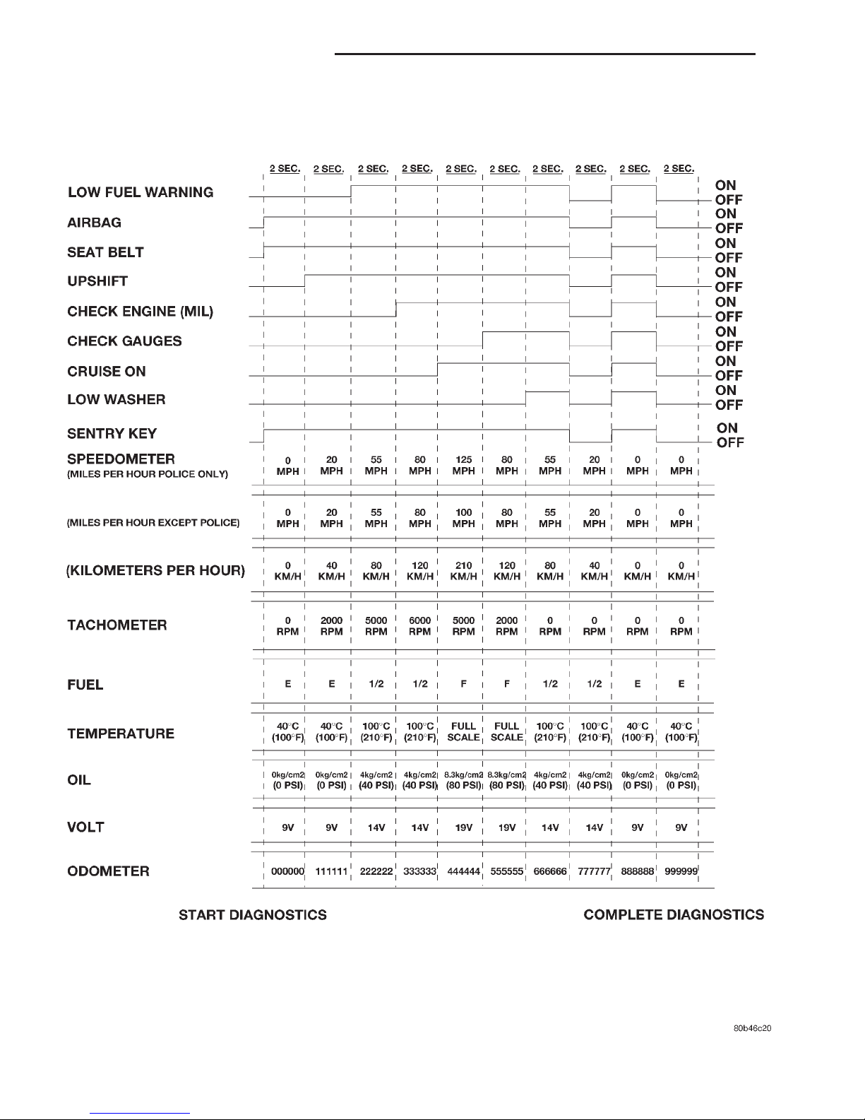
Fig. 2 High-Line Instrument Cluster Actuator Test
8E - 8 INSTRUMENT PANEL SYSTEMS XJ
DIAGNOSIS AND TESTING (Continued)
Page 9

while driving, refer Base Brake System for vehicles
not equipped with the four wheel anti-lock brake system, or refer to Antilock Brakes for vehicles
equipped with the four wheel anti-lock brake system
in the Diagnosis and Testing section of Group 5 Brakes for further diagnosis. If no brake system
problem is found, the following procedure will help
locate a short or open circuit, or a faulty switch. For
complete circuit diagrams, refer to Instrument
Cluster in the Contents of Group 8W - Wiring Diagrams.
(1) Check the fused ignition switch output (run/
start) fuse in the junction block. If OK, go to Step 2.
If not OK, repair the shorted circuit or component as
required and replace the faulty fuse.
(2) Turn the ignition switch to the On position.
Check for battery voltage at the fused ignition switch
output (run/start) fuse in the junction block. If OK,
go to Step 3. If not OK, repair the open fused ignition
switch output (run/start) circuit to the ignition switch
as required.
(3) Turn the ignition switch to the Off position.
Disconnect and isolate the battery negative cable.
Disconnect the wire harness connector at the park
brake switch. With the park brake released, check for
continuity between the park brake switch terminal
and a good ground. There should be no continuity. If
OK, go to Step 4. If not OK, adjust or replace the
faulty park brake switch.
(4) Disconnect the wire harness connector at the
brake warning switch. Check for continuity between
the two terminals of the brake warning switch. There
should be continuity. If OK, go to Step 5. If not OK,
replace the faulty brake warning switch.
(5) Check for continuity between each of the two
brake warning switch terminals and a good ground.
In each case, there should be no continuity. If OK, go
to Step 6. If not OK, replace the faulty brake warning switch.
(6) With both the park brake switch and the brake
warning switch wire harness connectors still disconnected, check for continuity between the red brake
warning indicator driver circuit cavity of the park
brake switch wire harness connector and a good
ground. There should be no continuity. If OK, go to
Step 7. If not OK, repair the shorted red brake warning indicator driver circuit as required.
(7) With the ignition switch held in the Start position, check for continuity between the red brake
warning indicator driver circuit cavity of the park
brake switch wire harness connector and a good
ground. There should be continuity. If OK, go to Step
8. If not OK, repair the open red brake warning indicator driver circuit to the ignition switch as required.
(8) Turn the ignition switch to the Off position.
Remove the instrument cluster. Check for continuity
between the red brake warning indicator driver circuit cavity of the instrument cluster wire harness
connector A and a good ground. There should be no
continuity. If OK, go to Step 9. If not OK, repair the
shorted red brake warning indicator driver circuit as
required.
(9) Check for continuity between the red brake
warning indicator driver circuit cavities of the instrument cluster wire harness connector A and the brake
warning switch wire harness connector. There should
be continuity. If OK, replace the faulty bulb. If not
OK, repair the open red brake warning indicator
driver circuit as required.
FOUR-WHEEL DRIVE INDICATOR LAMP - FULL TIME
The diagnosis found here addresses an inoperative
four-wheel drive indicator lamp condition. If the
problem being diagnosed is related to lamp accuracy,
be certain to confirm that the problem is with the
lamp or switch and not with a damaged or inoperative transfer case or transfer case linkage. Refer to
NV242 Diagnosis in the Diagnosis and Testing section of Group 21 - Transmission for more information. If no transfer case problem is found, the
following procedure will help locate a short or open
in the indicator lamp circuit. For complete circuit
diagrams, refer to Instrument Cluster in the Contents of Group 8W - Wiring Diagrams.
(1) Check the fused ignition switch output (run/
start) fuse in the junction block. If OK, go to Step 2.
If not OK, repair the shorted circuit or component as
required and replace the faulty fuse.
(2) Turn the ignition switch to the On position.
Check for battery voltage at the fused ignition switch
output (run/start) fuse in the junction block. If OK,
go to Step 3. If not OK, repair the open fused ignition
switch output (run/start) circuit to the ignition switch
as required.
(3) Turn the ignition switch to the Off position.
Disconnect and isolate the battery negative cable.
Disconnect the transfer case switch wire harness connector. Check for continuity between the ground circuit cavity of the transfer case switch wire harness
connector and a good ground. There should be continuity. If OK, go to Step 4. If not OK, repair the open
ground circuit to ground as required.
(4) Connect the battery negative cable. Turn the
ignition switch to the On position. Install a jumper
wire between the full time four wheel drive indicator
lamp driver circuit cavity of the transfer case switch
wire harness connector and a good ground. The full
time four-wheel drive indicator lamp should light. If
OK, replace the faulty transfer case switch. If not
OK, go to Step 5.
(5) Turn the ignition switch to the Off position.
Disconnect and isolate the battery negative cable.
XJ INSTRUMENT PANEL SYSTEMS 8E - 9
DIAGNOSIS AND TESTING (Continued)
Page 10

Remove the instrument cluster. With the transfer
case switch wire harness connector still disconnected,
check for continuity between the full time four wheel
drive indicator lamp driver circuit cavity of the
instrument cluster wire harness connector B and a
good ground. There should be no continuity. If OK, go
to Step 6. If not OK, repair the shorted full time four
wheel drive indicator lamp driver circuit as required.
(6) Check for continuity between the full time four
wheel drive indicator lamp driver circuit cavities of
the instrument cluster wire harness connector B and
the transfer case switch wire harness connector.
There should be continuity. If OK, replace the faulty
bulb. If not OK, repair the open full time four wheel
drive indicator lamp driver circuit as required.
FOUR-WHEEL DRIVE INDICATOR LAMP - PART TIME
The diagnosis found here addresses an inoperative
four-wheel drive indicator lamp condition. If the
problem being diagnosed is related to lamp accuracy,
be certain to confirm that the problem is with the
lamp or switch and not with a damaged or inoperative transfer case or transfer case linkage. Refer to
NV231 Diagnosis or NV242 Diagnosis in the Diagnosis and Testing section of Group 21 - Transmission
for more information. If no transfer case problem is
found, the following procedure will help locate a
short or open in the indicator lamp circuit. For complete circuit diagrams, refer to Instrument Cluster
in the Contents of Group 8W - Wiring Diagrams.
(1) Check the fused ignition switch output (run/
start) fuse in the junction block. If OK, go to Step 2.
If not OK, repair the shorted circuit or component as
required and replace the faulty fuse.
(2) Turn the ignition switch to the On position.
Check for battery voltage at the fused ignition switch
output (run/start) fuse in the junction block. If OK,
go to Step 3. If not OK, repair the open fused ignition
switch output (run/start) circuit to the ignition switch
as required.
(3) Turn the ignition switch to the Off position.
Disconnect and isolate the battery negative cable.
Disconnect the transfer case switch wire harness connector. Check for continuity between the ground circuit cavity of the transfer case switch wire harness
connector and a good ground. There should be continuity. If OK, go to Step 4. If not OK, repair the open
ground circuit to ground as required.
(4) Connect the battery negative cable. Turn the
ignition switch to the On position. Install a jumper
wire between the part time four wheel drive indicator
lamp driver circuit cavity of the transfer case switch
wire harness connector and a good ground. The part
time four-wheel drive indicator lamp should light. If
OK, replace the faulty transfer case switch. If not
OK, go to Step 5.
(5) Turn the ignition switch to the Off position.
Disconnect and isolate the battery negative cable.
Remove the instrument cluster. With the transfer
case switch wire harness connector still disconnected,
check for continuity between the part time four
wheel drive indicator lamp driver circuit cavity of the
instrument cluster wire harness connector B and a
good ground. There should be no continuity. If OK, go
to Step 6. If not OK, repair the shorted part time
four wheel drive indicator lamp driver circuit as
required.
(6) Check for continuity between the part time
four wheel drive indicator lamp driver circuit cavities
of the instrument cluster wire harness connector B
and the transfer case switch wire harness connector.
There should be continuity. If OK, replace the faulty
bulb. If not OK, repair the open part time four wheel
drive indicator lamp driver circuit as required.
HEADLAMP HIGH BEAM INDICATOR LAMP
The diagnosis found here addresses an inoperative
headlamp high beam indicator lamp condition. If the
problem being diagnosed is related to inoperative
headlamp high beams, refer to Headlamp Diagno-
sis in the Diagnosis and Testing section of Group 8L
- Lamps for diagnosis of the headlamp system. If no
headlamp system problems are found, the following
procedure will help locate an open in the high beam
indicator lamp circuit. For complete circuit diagrams,
refer to Instrument Cluster in the Contents of
Group 8W - Wiring Diagrams.
(1) Disconnect and isolate the battery negative
cable. Remove the instrument cluster.
(2) Connect the battery negative cable. Turn the
headlamps on and select the high beams with the
multi-function switch stalk. Check for battery voltage
at the high beam indicator driver circuit cavity of the
instrument cluster wire harness connector A. If OK,
replace the faulty bulb. If not OK, repair the open
high beam indicator driver circuit to the headlamp
dimmer (multi-function) switch as required.
LOW WASHER FLUID WARNING LAMP
The diagnosis found here addresses an inoperative
low washer fluid warning lamp condition. If the problem being diagnosed is related to lamp accuracy, be
certain to confirm that the problem is with the lamp
or washer fluid level sensor and not with a damaged
or empty washer fluid reservoir. Inspect the reservoir
for proper fluid level and signs of damage or distortion that could affect sensor performance before you
proceed with lamp diagnosis. Refer to Washer Sys-
tem in the Diagnosis and Testing section of Group
8K - Wiper and Washer Systems for more information. For complete circuit diagrams, refer to Instru-
8E - 10 INSTRUMENT PANEL SYSTEMS XJ
DIAGNOSIS AND TESTING (Continued)
Page 11

ment Cluster in the Contents of Group 8W - Wiring
Diagrams.
(1) Check the fused ignition switch output (run/
start) fuse in the junction block. If OK, go to Step 2.
If not OK, repair the shorted circuit or component as
required and replace the faulty fuse.
(2) Turn the ignition switch to the On position.
Check for battery voltage at the fused ignition switch
output (run/start) fuse in the junction block. If OK,
go to Step 3. If not OK, repair the open fused ignition
switch output (run/start) circuit to the ignition switch
as required.
(3) Turn the ignition switch to the Off position.
Disconnect the wire harness connector from the
washer fluid level sensor. Install a jumper wire
between the two cavities of the washer fluid level
sensor wire harness connector. Turn the ignition
switch to the On position. The low washer fluid
warning lamp should light. Remove the jumper wire
and the lamp should go off. If OK, replace the faulty
washer fluid level sensor. If not OK, go to Step 4.
(4) Turn the ignition switch to the Off position.
Check for continuity between the ground circuit cavity of the washer fluid level sensor wire harness connector and a good ground. There should be
continuity. If OK, go to Step 5. If not OK, repair the
open ground circuit to ground as required.
(5) Disconnect and isolate the battery negative
cable. Remove the instrument cluster. The washer
fluid level sensor wire harness connector is still disconnected. Check for continuity between the low
washer fluid level sense circuit cavity of the instrument cluster wire harness connector B and a good
ground. There should be no continuity. If OK, go to
Step 6. If not OK, repair the shorted low washer
fluid level sense circuit as required.
(6) Check for continuity between the low washer
fluid level sense circuit cavities of the instrument
cluster wire harness connector B and the washer
fluid level sensor wire harness connector. There
should be continuity. If OK, replace the faulty bulb.
If not OK, repair the open low washer fluid level
sense circuit as required.
TURN SIGNAL INDICATOR LAMP
The diagnosis found here addresses an inoperative
turn signal indicator lamp condition. For any other
turn signal problem, refer to Turn Signal and Haz-
ard Warning Systems in the Diagnosis and Testing
section of Group 8J - Turn Signal and Hazard Warning Systems for further diagnosis. If no turn signal or
hazard warning system problem is found, the following procedure will help locate a short or open in the
indicator lamp circuit. For complete circuit diagrams,
refer to Instrument Cluster in the Contents of
Group 8W - Wiring Diagrams.
(1) Disconnect and isolate the battery negative
cable. Remove the instrument cluster.
(2) Connect the battery negative cable. Activate
the hazard warning system by moving the hazard
warning switch button to the On position. Check for
battery voltage at the inoperative (right or left) turn
signal circuit cavity of the instrument cluster wire
harness connector (connector A - left, or connector B right). There should be a switching (on and off) battery voltage signal. If OK, replace the faulty (right or
left) indicator lamp bulb. If not OK, repair the open
(right or left) turn signal circuit to the turn signal/
hazard warning (multi-function) switch as required.
INSTRUMENT PANEL CIGAR LIGHTER
For complete circuit diagrams, refer to Horn/Cigar Lighter in the Contents of Group 8W - Wiring
Diagrams.
WARNING: ON VEHICLES EQUIPPED WITH AIRBAGS, REFER TO GROUP 8M - PASSIVE
RESTRAINT SYSTEMS BEFORE ATTEMPTING ANY
STEERING WHEEL, STEERING COLUMN, OR
INSTRUMENT PANEL COMPONENT DIAGNOSIS OR
SERVICE. FAILURE TO TAKE THE PROPER PRECAUTIONS COULD RESULT IN ACCIDENTAL AIRBAG DEPLOYMENT AND POSSIBLE PERSONAL
INJURY.
(1) Remove the cigar lighter knob and element
from the cigar lighter receptacle shell. Check for continuity between the inside circumference of the cigar
lighter receptacle shell and a good ground. there
should be continuity. If OK, go to Step 2. If not OK,
go to Step 3.
(2) Turn the ignition switch to the On position.
Check for battery voltage at the insulated contact
located at the back of the cigar lighter receptacle
shell. If OK, replace the faulty cigar lighter knob and
element. If not OK, go to Step 3.
(3) Turn the ignition switch to the Off position.
Disconnect and isolate the battery negative cable.
Remove the instrument panel accessory switch bezel.
Check for continuity between the ground circuit cavity of the cigar lighter wire harness connector and a
good ground. There should be continuity. If OK, go to
Step 4. If not OK, repair the open ground circuit to
ground as required.
(4) Connect the battery negative cable. Turn the
ignition switch to the Accessory or On positions.
Check for battery voltage at the cigar lighter relay
output circuit cavity of the cigar lighter wire harness
connector. If OK, replace the faulty cigar lighter
receptacle (instrument panel accessory switch bezel
unit). If not OK, refer to Cigar Lighter Relay in
the Diagnosis and Testing section of this group for
further diagnosis.
XJ INSTRUMENT PANEL SYSTEMS 8E - 11
DIAGNOSIS AND TESTING (Continued)
Page 12

CIGAR LIGHTER RELAY
The cigar lighter relay (Fig. 3) is located in the
junction block, on the right cowl side inner panel
below the instrument panel in the passenger compartment. For complete circuit diagrams, refer to
Horn/Cigar Lighter in the Contents of Group 8W Wiring Diagrams.
WARNING: ON VEHICLES EQUIPPED WITH AIRBAGS, REFER TO GROUP 8M - PASSIVE
RESTRAINT SYSTEMS BEFORE ATTEMPTING ANY
STEERING WHEEL, STEERING COLUMN, OR
INSTRUMENT PANEL COMPONENT DIAGNOSIS OR
SERVICE. FAILURE TO TAKE THE PROPER PRECAUTIONS COULD RESULT IN ACCIDENTAL AIRBAG DEPLOYMENT AND POSSIBLE PERSONAL
INJURY.
(1) Remove the cigar lighter relay from the junction block. Refer to Cigar Lighter Relay in the
Removal and Installation section of this group for the
procedures.
(2) A relay in the de-energized position should
have continuity between terminals 87A and 30, and
no continuity between terminals 87 and 30. If OK, go
to Step 3. If not OK, replace the faulty relay.
(3) Resistance between terminals 85 and 86 (electromagnet) should be 75 6 5 ohms. If OK, go to Step
4. If not OK, replace the faulty relay.
(4) Connect a battery to terminals 85 and 86.
There should now be continuity between terminals
30 and 87, and no continuity between terminals 87A
and 30. If OK, perform the Relay Circuit Test that
follows. If not OK, replace the faulty relay.
RELAY CIRCUIT TEST
(1) The relay common feed terminal cavity (30) of
the junction block is connected to battery voltage and
should be hot at all times. Check for battery voltage
at the fused B(+) circuit cavity of the accessory relay
wire harness connector. If OK, go to Step 2. If not
OK, repair the fused B(+) circuit to the fuse in the
junction block as required.
(2) The relay normally closed terminal (87A) is
connected to terminal 30 in the de-energized position,
but is not used for this application. Go to Step 3.
(3) The relay normally open terminal (87) is connected to the common feed terminal (30) in the energized position. This terminal supplies battery voltage
to the cigar lighter when the relay is energized by
the ignition switch. There should be continuity
between the junction block cavity for relay terminal
87 and the cigar lighter relay output circuit cavity of
the cigar lighter wire harness connector at all times.
If OK, go to Step 4. If not OK, repair the open cigar
lighter relay output circuit to the cigar lighter wire
harness connector as required.
(4) The coil battery terminal (86) is connected to
the electromagnet in the relay. It receives battery
feed to energize the cigar lighter relay when the ignition switch is in the Accessory or On positions. Turn
the ignition switch to the On position. Check for battery voltage at the fused ignition switch output (acc/
run) circuit cavity for relay terminal 86 in the
junction block. If OK, go to Step 5. If not OK, repair
the open fused ignition switch output (acc/run) circuit
to the ignition switch as required.
(5) The coil ground terminal (85) is connected to
the electromagnet in the relay. The junction block
cavity for this terminal should have continuity to
ground at all times. If not OK, repair the open
ground circuit to ground as required.
INSTRUMENT PANEL POWER OUTLET
For complete circuit diagrams, refer to Horn/Cigar Lighter in the Contents of Group 8W - Wiring
Diagrams.
WARNING: ON VEHICLES EQUIPPED WITH AIRBAGS, REFER TO GROUP 8M - PASSIVE
RESTRAINT SYSTEMS BEFORE ATTEMPTING ANY
STEERING WHEEL, STEERING COLUMN, OR
INSTRUMENT PANEL COMPONENT DIAGNOSIS OR
SERVICE. FAILURE TO TAKE THE PROPER PRECAUTIONS COULD RESULT IN ACCIDENTAL AIRBAG DEPLOYMENT AND POSSIBLE PERSONAL
INJURY.
(1) Check the fused B(+) fuse in the junction block.
If OK, go to Step 2. If not OK, repair the shorted circuit or component as required and replace the faulty
fuse.
(2) Check for battery voltage at the fused B(+) fuse
in the junction block. If OK, go to Step 3. If not OK,
repair the open fused B(+) circuit to the Power Distribution Center (PDC) as required.
Fig. 3 Cigar Lighter Relay
8E - 12 INSTRUMENT PANEL SYSTEMS XJ
DIAGNOSIS AND TESTING (Continued)
Page 13

(3) Remove the plastic protective cap from the
power outlet receptacle. Check for continuity between
the inside circumference of the power outlet receptacle and a good ground. There should be continuity. If
OK, go to Step 4. If not OK, go to Step 5.
(4) Check for battery voltage at the insulated contact located at the back of the power outlet receptacle. If not OK, go to Step 5.
(5) Disconnect and isolate the battery negative
cable. Remove the instrument panel accessory switch
bezel. Check for continuity between the ground circuit cavity of the power outlet wire harness connector
and a good ground. There should be continuity. If
OK, go to Step 6. If not OK, repair the open ground
circuit to ground as required.
(6) Connect the battery negative cable. Check for
battery voltage at the fused B(+) circuit cavity of the
power outlet wire harness connector. If OK, replace
the faulty power outlet receptacle (instrument panel
accessory switch bezel unit). If not OK, repair the
open fused B(+) circuit to the junction block fuse as
required.
REMOVAL AND INSTALLATION
STEERING COLUMN OPENING COVER
WARNING: ON VEHICLES EQUIPPED WITH AIRBAGS, REFER TO GROUP 8M - PASSIVE
RESTRAINT SYSTEMS BEFORE ATTEMPTING ANY
STEERING WHEEL, STEERING COLUMN, OR
INSTRUMENT PANEL COMPONENT DIAGNOSIS OR
SERVICE. FAILURE TO TAKE THE PROPER PRECAUTIONS COULD RESULT IN ACCIDENTAL AIRBAG DEPLOYMENT AND POSSIBLE PERSONAL
INJURY.
REMOVAL
(1) Disconnect and isolate the battery negative
cable.
(2) If the vehicle is so equipped, move the tilt
steering column to the fully raised position.
(3) Remove the three screws that secure the lower
edge of the steering column opening cover to the
lower instrument panel reinforcement (Fig. 4).
(4) Using a trim stick or another suitable wide
flat-bladed tool, gently pry the upper edge of the
steering column opening cover just below the cluster
bezel on each side of the steering column away from
the instrument panel far enough to disengage the
two snap clip retainers from the receptacles in the
instrument panel.
(5) Remove the steering column opening cover
from the instrument panel.
INSTALLATION
(1) Position the steering column opening cover to
the instrument panel.
(2) Align the snap clip retainers on the steering
column opening cover with the receptacles in the
instrument panel.
(3) Press firmly on the steering column opening
cover over the snap clip locations until each of the
snap clips is fully engaged in its receptacle.
(4) Install and tighten the three screws that secure
the lower edge of the steering column opening cover
to the lower instrument panel reinforcement. Tighten
the screws to 2.2 N·m (20 in. lbs.).
(5) Reconnect the battery negative cable.
KNEE BLOCKER
WARNING: ON VEHICLES EQUIPPED WITH AIRBAGS, REFER TO GROUP 8M - PASSIVE
RESTRAINT SYSTEMS BEFORE ATTEMPTING ANY
STEERING WHEEL, STEERING COLUMN, OR
INSTRUMENT PANEL COMPONENT DIAGNOSIS OR
SERVICE. FAILURE TO TAKE THE PROPER PRECAUTIONS COULD RESULT IN ACCIDENTAL AIRBAG DEPLOYMENT AND POSSIBLE PERSONAL
INJURY.
INSTALLATION
(1) Disconnect and isolate the battery negative
cable.
(2) Remove the steering column opening cover
from the instrument panel. Refer to Steering Col-
umn Opening Cover in the Removal and Installation section of this group for the procedures.
(3) Remove the two screws that secure the knee
blocker to the instrument panel (Fig. 5).
Fig. 4 Steering Column Opening Cover Remove/
Install
XJ INSTRUMENT PANEL SYSTEMS 8E - 13
DIAGNOSIS AND TESTING (Continued)
Page 14

(4) Pull the upper edge of the knee blocker away
from the instrument panel far enough to disengage
the two lower mounting tabs from the mounting slots
in the lower instrument panel reinforcement.
(5) Remove the knee blocker from the instrument
panel.
INSTALLATION
(1) Position the knee blocker to the instrument
panel.
(2) Install and tighten the four screws that secure
the knee blocker to the instrument panel. Tighten
the screws to 2.2 N·m (20 in. lbs.). Be certain that
the mounting screws are located in the screw hole on
each side of the steering column that is closest to the
driver side front door of the vehicle (Fig. 6).
(3) Install the steering column opening cover onto
the instrument panel. Refer to Steering Column
Opening Cover in the Removal and Installation section of this group for the procedures.
(4) Reconnect the battery negative cable.
INSTRUMENT PANEL CENTER BEZEL
WARNING: ON VEHICLES EQUIPPED WITH AIRBAGS, REFER TO GROUP 8M - PASSIVE
RESTRAINT SYSTEMS BEFORE ATTEMPTING ANY
STEERING WHEEL, STEERING COLUMN, OR
INSTRUMENT PANEL COMPONENT DIAGNOSIS OR
SERVICE. FAILURE TO TAKE THE PROPER PRECAUTIONS COULD RESULT IN ACCIDENTAL AIRBAG DEPLOYMENT AND POSSIBLE PERSONAL
INJURY.
REMOVAL
(1) Disconnect and isolate the battery negative
cable.
(2) Using a trim stick or another suitable wide
flat-bladed tool, gently pry the instrument panel center bezel away from the instrument panel far enough
to disengage the six snap clip retainers that secure it
from the receptacles in the instrument panel (Fig. 7).
(3) Remove the center bezel from the instrument
panel.
INSTALLATION
(1) Position the center bezel to the instrument
panel.
(2) Align the snap clips on the center bezel with
the receptacles in the instrument panel.
(3) Press firmly on the center bezel over each of
the snap clip locations until each of the six snap clips
is fully engaged in its receptacle on the instrument
panel.
(4) Reconnect the battery negative cable.
Fig. 5 Knee Blocker Remove/Install
Fig. 6 Knee Blocker Mounting Screw Location
Fig. 7 Instrument Panel Center Bezel Remove/Install
8E - 14 INSTRUMENT PANEL SYSTEMS XJ
REMOVAL AND INSTALLATION (Continued)
Page 15

INSTRUMENT PANEL ACCESSORY SWITCH
BEZEL
WARNING: ON VEHICLES EQUIPPED WITH AIRBAGS, REFER TO GROUP 8M - PASSIVE
RESTRAINT SYSTEMS BEFORE ATTEMPTING ANY
STEERING WHEEL, STEERING COLUMN, OR
INSTRUMENT PANEL COMPONENT DIAGNOSIS OR
SERVICE. FAILURE TO TAKE THE PROPER PRECAUTIONS COULD RESULT IN ACCIDENTAL AIRBAG DEPLOYMENT AND POSSIBLE PERSONAL
INJURY.
REMOVAL
(1) Disconnect and isolate the battery negative
cable.
(2) Remove the center bezel from the instrument
panel. Refer to Instrument Panel Center Bezel in
the Removal and Installation section of this group for
the procedures.
(3) Remove the three screws that secure the accessory switch bezel to the instrument panel (Fig. 8).
(4) Pull the accessory switch bezel away from the
instrument panel far enough to access the instrument panel wire harness connectors.
(5) Disconnect the instrument panel wire harness
connectors from the connector receptacles, the accessory switches, the cigar lighter and the accessory
power outlet on the back of the accessory switch
bezel.
(6) Remove the accessory switch bezel from the
instrument panel.
INSTALLATION
(1) Position the accessory switch bezel to the
instrument panel.
(2) Reconnect the instrument panel wire harness
connectors to the connector receptacles, the accessory
switches, the cigar lighter and the accessory power
outlet on the back of the accessory switch bezel.
(3) Position the accessory switch bezel onto the
instrument panel.
(4) Install and tighten the three screws that secure
the accessory switch bezel to the instrument panel.
Tighten the screws to 2.2 N·m (20 in. lbs.).
(5) Install the center bezel onto the instrument
panel. Refer to Instrument Panel Center Bezel in
the Removal and Installation section of this group for
the procedures.
(6) Reconnect the battery negative cable.
CIGAR LIGHTER RELAY
WARNING: ON VEHICLES EQUIPPED WITH AIRBAGS, REFER TO GROUP 8M - PASSIVE
RESTRAINT SYSTEMS BEFORE ATTEMPTING ANY
STEERING WHEEL, STEERING COLUMN, OR
INSTRUMENT PANEL COMPONENT DIAGNOSIS OR
SERVICE. FAILURE TO TAKE THE PROPER PRECAUTIONS COULD RESULT IN ACCIDENTAL AIRBAG DEPLOYMENT AND POSSIBLE PERSONAL
INJURY.
REMOVAL
(1)
Disconnect and isolate the battery negative cable.
(2) Remove the fuse access panel by unsnapping it
from the right cowl side trim panel.
(3) Remove the stamped nut that secures the right
cowl side trim to the junction block stud (Fig. 9).
(4) Remove the screw located above the fuse access
opening that secures the right cowl side trim to the
right cowl side inner panel.
(5) Remove the screw that secures the right door
sill trim and the right cowl side trim to the right
door opening sill.
(6) Remove the right cowl side trim panel from the
vehicle.
(7) Refer to Junction Block in the Contents of
Group 8W - Wiring Diagrams for cigar lighter relay
identification and location.
(8) Remove the cigar lighter relay from the receptacle in the junction block.
INSTALLATION
(1) Refer to Junction Block in the Contents of
Group 8W - Wiring Diagrams for the proper cigar
lighter relay location.
(2) Position the cigar lighter relay to the receptacle
in the junction block.
(3) Align the terminals of the cigar lighter relay
with the cavities in the junction block receptacle.
(4) Push on the cigar lighter relay case firmly and
evenly until all of the relay terminals are fully seated
within the cavities of the junction block receptacle.
Fig. 8 Instrument Panel Accessory Switch Bezel
Remove/Install
XJ INSTRUMENT PANEL SYSTEMS 8E - 15
REMOVAL AND INSTALLATION (Continued)
Page 16

(5) Position the right cowl side trim to the right
door sill trim.
(6) Install and tighten the screw that secures the
right cowl side trim to the right door sill trim.
Tighten the screw to 2.2 N·m (20 in. lbs.).
(7) Position the right cowl side trim to the right
cowl side inner panel.
(8) Install and tighten the screw that secures the
right cowl side trim to the right cowl side inner
panel. Tighten the screw to 2.2 N·m (20 in. lbs.).
(9) Install the stamped nut that secures the right
cowl side trim to the junction block stud.
(10) Install the fuse access panel by snapping it
onto the right cowl side trim panel.
(11) Reconnect the battery negative cable.
CLUSTER BEZEL
WARNING: ON VEHICLES EQUIPPED WITH AIRBAGS, REFER TO GROUP 8M - PASSIVE
RESTRAINT SYSTEMS BEFORE ATTEMPTING ANY
STEERING WHEEL, STEERING COLUMN, OR
INSTRUMENT PANEL COMPONENT DIAGNOSIS OR
SERVICE. FAILURE TO TAKE THE PROPER PRECAUTIONS COULD RESULT IN ACCIDENTAL AIRBAG DEPLOYMENT AND POSSIBLE PERSONAL
INJURY.
REMOVAL
(1) Disconnect and isolate the battery negative
cable.
(2) Remove the knee blocker from the instrument
panel. Refer to Knee Blocker in the Removal and
Installation section of this group for the procedures.
(3) Remove the center bezel from the instrument
panel. Refer to Instrument Panel Center Bezel in
the Removal and Installation section of this group for
the procedures.
(4) Remove the four screws exposed by the center
bezel removal that secure the cluster bezel to the
instrument panel.
(5) Remove the headlamp switch knob and shaft
from the headlamp switch. Refer to Headlamp
Switch in the Removal and Installation section of
this group for the procedures.
(6) Disengage the two ends of the steering column
sight shield from each other at the connector located
below the lower steering column shroud (Fig. 10).
(7) If the vehicle is so equipped, set the tilt steering column in its lowest position.
(8) Using a trim stick or another suitable wide
flat-bladed tool, gently pry around the perimeter of
the cluster bezel to disengage the five snap clips from
their receptacles in the instrument panel.
(9) Remove the cluster bezel from the instrument
panel.
INSTALLATION
(1) Position the cluster bezel to the instrument
panel.
(2) Align the snap clips on the cluster bezel with
the receptacles in the instrument panel.
Fig. 9 Right Cowl Side Trim Remove/Install
Fig. 10 Cluster Bezel Remove/Install
8E - 16 INSTRUMENT PANEL SYSTEMS XJ
REMOVAL AND INSTALLATION (Continued)
Page 17

(3) Press firmly on the cluster bezel over each of
the snap clip locations until each of the snap clips is
fully engaged in its receptacle.
(4) Engage the two ends of the steering column
sight shield with each other at the connector located
below the lower steering column shroud.
(5) Install the headlamp switch knob and shaft
onto the headlamp switch. Refer to Headlamp
Switch in the Removal and Installation section of
this group for the procedures.
(6) Install and tighten the four screws that secure
the cluster bezel to the instrument panel beneath the
instrument panel center bezel. Tighten the screws to
2.2 N·m (20 in. lbs.).
(7) Install the center bezel onto the instrument
panel. Refer to Instrument Panel Center Bezel in
the Removal and Installation section of this group for
the procedures.
(8) Install the knee blocker onto the instrument
panel. Refer to Knee Blocker in the Removal and
Installation section of this group for the procedures.
Be certain that the two ends of the steering column
sight shield connector are engaged with each other
before installing the knee blocker.
(9) Reconnect the battery negative cable.
HEADLAMP SWITCH
WARNING: ON VEHICLES EQUIPPED WITH AIRBAGS, REFER TO GROUP 8M - PASSIVE
RESTRAINT SYSTEMS BEFORE ATTEMPTING ANY
STEERING WHEEL, STEERING COLUMN, OR
INSTRUMENT PANEL COMPONENT DIAGNOSIS OR
SERVICE. FAILURE TO TAKE THE PROPER PRECAUTIONS COULD RESULT IN ACCIDENTAL AIRBAG DEPLOYMENT AND POSSIBLE PERSONAL
INJURY.
WARNING: IF THE HEADLAMP SWITCH WAS ON,
WAIT FIVE MINUTES TO ALLOW THE CERAMIC
DIMMER RESISTOR TO COOL. IF THE CERAMIC
DIMMER RESISTOR IS NOT ALLOWED TO COOL, IT
CAN BURN YOUR FINGERS.
REMOVAL
(1) Disconnect and isolate the battery negative
cable.
(2) Remove the knee blocker from the instrument
panel. Refer to Knee Blocker in the Removal and
Installation section of this group for the procedures.
(3) Pull the headlamp switch control knob out to
the On position stop.
(4) Reach up under the instrument panel through
the outboard side of the steering column opening to
access and depress the headlamp switch control knob
and shaft release button on the inboard side of the
switch body.
(5) While holding the release button depressed,
pull the headlamp switch control knob and shaft out
of the headlamp switch.
(6) Remove the spanner nut that secures the headlamp switch to the instrument panel (Fig. 11).
(7) Pull the headlamp switch into the steering column opening area of the instrument panel far
enough to access the instrument panel wire harness
connectors.
(8) Disconnect the two instrument panel wire harness connectors from the headlamp switch.
(9) Remove the headlamp switch from the instrument panel.
INSTALLATION
(1) Position the headlamp switch to the instrument panel steering column opening.
(2) Reconnect the two instrument panel wire harness connectors to the headlamp switch.
(3) Position the headlamp switch behind its
mounting hole on the instrument panel.
(4) Install and tighten the spanner nut that
secures the headlamp switch to the instrument
panel. Tighten the nut to 2.7 N·m (24 in. lbs.).
(5) Insert the shaft of the headlamp switch control
knob and shaft unit through the opening in the spanner nut and into the headlamp switch.
(6) Push the headlamp switch control knob and
shaft unit all the way into the headlamp switch body.
(7) Install the knee blocker onto the instrument
panel. Refer to Knee Blocker in the Removal and
Installation section of this group for the procedures.
(8) Reconnect the battery negative cable.
Fig. 11 Headlamp Switch Remove/Install
XJ INSTRUMENT PANEL SYSTEMS 8E - 17
REMOVAL AND INSTALLATION (Continued)
Page 18

INSTRUMENT CLUSTER
WARNING: ON VEHICLES EQUIPPED WITH AIRBAGS, REFER TO GROUP 8M - PASSIVE
RESTRAINT SYSTEMS BEFORE ATTEMPTING ANY
STEERING WHEEL, STEERING COLUMN, OR
INSTRUMENT PANEL COMPONENT DIAGNOSIS OR
SERVICE. FAILURE TO TAKE THE PROPER PRECAUTIONS COULD RESULT IN ACCIDENTAL AIRBAG DEPLOYMENT AND POSSIBLE PERSONAL
INJURY.
REMOVAL
(1) Disconnect and isolate the battery negative
cable.
(2) Remove the cluster bezel from the instrument
panel. Refer to Cluster Bezel in the Removal and
Installation section of this group for the procedures.
(3) Remove the four screws that secure the instrument cluster to the instrument panel (Fig. 12).
(4) Pull the instrument cluster rearward far
enough to disengage the two self-docking instrument
panel wire harness connectors from the connector
receptacles on the back of the cluster housing. Do
not pull on the instrument cluster by the lens
or mask sections, or the cluster components
may become separated.
(5) Remove the instrument cluster from the instrument panel.
INSTALLATION
(1) Position the instrument cluster to the instrument panel.
(2) Align the instrument cluster with the cluster
opening in the instrument panel and push the cluster
firmly and evenly into place. The instrument panel
has two self-docking wire harness connectors that
will be automatically aligned with, and connected to
the cluster connector receptacles when the cluster is
installed in the instrument panel.
(3) Install and tighten the four screws that secure
the instrument cluster to the instrument panel.
Tighten the screws to 2.2 N·m (20 in. lbs.).
(4) Install the cluster bezel onto the instrument
panel. Refer to Cluster Bezel in the Removal and
Installation section of this group for the procedures.
(5) Reconnect the battery negative cable.
INSTRUMENT CLUSTER COMPONENTS
Some of the components for the instrument cluster
used in this vehicle are serviced individually. The
serviced components include: the incandescent
instrument cluster indicator lamp and illumination
lamp bulbs (including the integral bulb holders), the
odometer reset knob boot, the cluster lens, the cluster hood and mask unit, the instrument cluster housing rear cover, and the instrument cluster housing
(including the odometer reset knob, the gauge mask,
the gauges and the instrument cluster electronic circuit board). Following are the service procedures for
the instrument cluster components.
WARNING: ON VEHICLES EQUIPPED WITH AIRBAGS, REFER TO GROUP 8M - PASSIVE
RESTRAINT SYSTEMS BEFORE ATTEMPTING ANY
STEERING WHEEL, STEERING COLUMN, OR
INSTRUMENT PANEL COMPONENT DIAGNOSIS OR
SERVICE. FAILURE TO TAKE THE PROPER PRECAUTIONS COULD RESULT IN ACCIDENTAL AIRBAG DEPLOYMENT AND POSSIBLE PERSONAL
INJURY.
REMOVAL
CLUSTER BULB
This procedure applies to each of the incandescent
cluster illumination lamp or indicator lamp bulb and
bulb holder units. However, the illumination lamps
and the indicator lamps use different bulb and bulb
holder unit sizes. They must never be interchanged.
Be certain that any bulb and bulb holder unit
removed from the cluster electronic circuit board is
reinstalled in the correct position. Always use the
correct bulb size and type for replacement. An incorrect bulb size or type may overheat and cause damage to the instrument cluster, the electronic circuit
board and/or the gauges.
(1) Disconnect and isolate the battery negative
cable.
(2) Remove the instrument cluster from the instrument panel. Refer to Instrument Cluster in the
Removal and Installation section of this group for the
procedures.
Fig. 12 Instrument Cluster Remove/Install
8E - 18 INSTRUMENT PANEL SYSTEMS XJ
REMOVAL AND INSTALLATION (Continued)
Page 19

(3) Turn the bulb holder counterclockwise about
sixty degrees on the cluster electronic circuit board.
(4) Pull the bulb and bulb holder unit straight
back to remove it from the bulb mounting hole in the
cluster electronic circuit board (Fig. 13).
CLUSTER LENS
(1) Disconnect and isolate the battery negative
cable.
(2) Remove the instrument cluster from the instrument panel. Refer to Instrument Cluster in the
Removal and Installation section of this group for the
procedures.
(3) Work around the perimeter of the cluster housing to disengage each of the latches that secure the
cluster lens to the cluster housing (Fig. 14).
(4) Gently pull the cluster lens away from the clus-
ter housing.
ODOMETER RESET KNOB BOOT
(1) Disconnect and isolate the battery negative
cable.
(2) Remove the instrument cluster from the instrument panel. Refer to Instrument Cluster in the
Removal and Installation section of this group for the
procedures.
(3) Remove the cluster lens from the cluster housing. Refer to Instrument Cluster Components -
Cluster Lens in the Removal and Installation section of this group for the procedures.
(4) Remove the odometer reset knob boot by pulling it out of the cluster lens.
CLUSTER HOOD AND MASK
(1) Disconnect and isolate the battery negative
cable.
(2) Remove the instrument cluster from the instrument panel. Refer to Instrument Cluster in the
Removal and Installation section of this group for the
procedures.
(3) Remove the cluster lens from the cluster housing. Refer to Instrument Cluster Components -
Cluster Lens in the Removal and Installation section of this group for the procedures.
Fig. 13 Cluster Bulb Locations
Fig. 14 Instrument Cluster Components
XJ INSTRUMENT PANEL SYSTEMS 8E - 19
REMOVAL AND INSTALLATION (Continued)
Page 20

(4) Work around the perimeter of the cluster housing to disengage each of the latches that secure the
cluster hood and mask unit to the cluster housing
(Fig. 14).
(5) Gently pull the cluster hood and mask unit
away from the cluster housing.
CLUSTER HOUSING REAR COVER
(1) Disconnect and isolate the battery negative
cable.
(2) Remove the instrument cluster from the instrument panel. Refer to Instrument Cluster in the
Removal and Installation section of this group for the
procedures.
(3) Work around the perimeter of the cluster housing to disengage each of the latches that secure the
rear cover to the cluster housing (Fig. 14).
(4) Gently pull the rear cover away from the back
of the cluster housing.
CLUSTER HOUSING
(1) Disconnect and isolate the battery negative
cable.
(2) Remove the instrument cluster from the instrument panel. Refer to Instrument Cluster in the
Removal and Installation section of this group for the
procedures.
(3) Remove all of the cluster illumination lamp
and indicator lamp bulb and bulb holder units from
the electronic circuit board. Refer to Instrument
Cluster Components - Cluster Bulbs in the
Removal and Installation section of this group for the
procedures.
(4) Remove the cluster hood and mask unit from
the cluster housing. Refer to Instrument Cluster
Components - Cluster Hood and Mask in the
Removal and Installation section of this group for the
procedures.
(5) Remove the rear cover from the cluster housing. Refer to Instrument Cluster Components -
Cluster Housing Rear Cover in the Removal and
Installation section of this group for the procedures.
INSTALLATION
CLUSTER BULB
This procedure applies to each of the incandescent
cluster illumination lamp or indicator lamp bulb and
bulb holder units. However, the illumination lamps
and the indicator lamps use different bulb and bulb
holder unit sizes. They must never be interchanged.
Be certain that any bulb and bulb holder unit
removed from the cluster electronic circuit board is
reinstalled in the correct position.
CAUTION: Always use the correct bulb size and
type for replacement. An incorrect bulb size or type
may overheat and cause damage to the instrument
cluster, the electronic circuit board and/or the
gauges.
(1) Insert the bulb and bulb holder unit straight
into the correct bulb mounting hole in the cluster
electronic circuit board.
(2) With the bulb holder fully seated against the
cluster electronic circuit board, turn the bulb holder
clockwise about sixty degrees to lock it into place.
(3) Install the instrument cluster onto the instrument panel. Refer to Instrument Cluster in the
Removal and Installation section of this group for the
procedures.
(4) Reconnect the battery negative cable.
CLUSTER LENS
(1) Align the cluster lens with the cluster hood and
mask unit.
(2) Press firmly and evenly on the cluster lens to
install it onto the cluster housing.
(3) Work around the perimeter of the cluster housing to be certain that each of the latches that secure
the cluster lens to the cluster housing is fully
engaged.
(4) Install the instrument cluster onto the instrument panel. Refer to Instrument Cluster in the
Removal and Installation section of this group for the
procedures.
(5) Reconnect the battery negative cable.
ODOMETER RESET KNOB BOOT
(1) Position the odometer reset knob to the mounting hole from the back of the cluster lens.
(2) Pull the odometer reset knob into the mounting
hole from the face of the cluster lens.
(3) Install the cluster lens onto the cluster housing. Refer to Instrument Cluster Components -
Cluster Lens in the Removal and Installation section of this group for the procedures.
(4) Install the instrument cluster onto the instrument panel. Refer to Instrument Cluster in the
Removal and Installation section of this group for the
procedures.
(5) Reconnect the battery negative cable.
CLUSTER HOOD AND MASK
(1) Align the hood and mask unit with the cluster
housing.
(2) Press firmly and evenly on the hood and mask
unit to install it onto the cluster housing.
(3) Work around the perimeter of the cluster housing to be certain that each of the latches that secure
the hood and mask unit to the cluster housing is
fully engaged.
8E - 20 INSTRUMENT PANEL SYSTEMS XJ
REMOVAL AND INSTALLATION (Continued)
Page 21

(4) Install the cluster lens onto the cluster housing. Refer to Instrument Cluster Components -
Cluster Lens in the Removal and Installation section of this group for the procedures.
(5) Install the instrument cluster onto the instrument panel. Refer to Instrument Cluster in the
Removal and Installation section of this group for the
procedures.
(6) Reconnect the battery negative cable.
CLUSTER HOUSING REAR COVER
(1) Position the rear cover to the back of the cluster housing.
(2) Press firmly and evenly on the rear cover until
each of the latches that secure the rear cover to the
cluster housing is fully engaged.
(3) Install the instrument cluster onto the instrument panel. Refer to Instrument Cluster in the
Removal and Installation section of this group for the
procedures.
(4) Reconnect the battery negative cable.
CLUSTER HOUSING
(1) Install the rear cover onto the cluster housing.
Refer to Instrument Cluster Components - Clus-
ter Housing Rear Cover in the Removal and
Installation section of this group for the procedures.
(2) Install the cluster hood and mask unit onto the
cluster housing. Refer to Instrument Cluster Com-
ponents - Cluster Hood and Mask in the Removal
and Installation section of this group for the procedures.
(3) Install all of the cluster illumination lamp and
indicator lamp bulb and bulb holder units into the
electronic circuit board. Refer to Instrument Clus-
ter Components - Cluster Bulbs in the Removal
and Installation section of this group for the procedures.
(4) Install the instrument cluster onto the instrument panel. Refer to Instrument Cluster in the
Removal and Installation section of this group for the
procedures.
(5) Reconnect the battery negative cable.
INSTRUMENT PANEL TOP COVER
WARNING: ON VEHICLES EQUIPPED WITH AIRBAGS, REFER TO GROUP 8M - PASSIVE
RESTRAINT SYSTEMS BEFORE ATTEMPTING ANY
STEERING WHEEL, STEERING COLUMN, OR
INSTRUMENT PANEL COMPONENT DIAGNOSIS OR
SERVICE. FAILURE TO TAKE THE PROPER PRECAUTIONS COULD RESULT IN ACCIDENTAL AIRBAG DEPLOYMENT AND POSSIBLE PERSONAL
INJURY.
REMOVAL
(1) Disconnect and isolate the battery negative
cable.
(2) Remove the cluster bezel from the instrument
panel. Refer to Cluster Bezel in the Removal and
Installation section of this group for the procedures.
(3) Using a trim stick or another suitable wide
flat-bladed tool, gently pry the rear edge (farthest
from the windshield) of the instrument panel top
cover up and away from the instrument panel far
enough to disengage the seven snap clip retainers
from their receptacles in the instrument panel (Fig.
15).
(4) Pull the top cover sharply rearwards (away
from the windshield) to disengage the four snap clip
retainers that secure the forward edge of the top
cover from their receptacles in the instrument panel
near the base of the windshield.
(5) Remove the top cover from the instrument
panel.
INSTALLATION
(1) Position the top cover onto the instrument
panel.
(2) Align the four snap clips on the forward edge
(nearest the windshield) of the top cover with the
snap clip receptacles in the instrument panel.
(3) Press firmly downward on the top cover over
each of the four forward snap clip locations until
each of the snap clips is fully seated in their receptacles in the instrument panel.
(4) Align the seven snap clips on the rear edge
(farthest from the windshield) of the top cover with
the snap clip receptacles in the instrument panel.
(5) Press firmly downward on the top cover over
each of the seven rearward snap clip locations until
each of the snap clips is fully seated in their receptacles in the instrument panel.
Fig. 15 Instrument Panel Top Cover Remove/Install
XJ INSTRUMENT PANEL SYSTEMS 8E - 21
REMOVAL AND INSTALLATION (Continued)
Page 22

(6) Install the cluster bezel onto the instrument
panel. Refer to Cluster Bezel in the Removal and
Installation section of this group for the procedures.
(7) Reconnect the battery negative cable.
GLOVE BOX
WARNING: ON VEHICLES EQUIPPED WITH AIRBAGS, REFER TO GROUP 8M - PASSIVE
RESTRAINT SYSTEMS BEFORE ATTEMPTING ANY
STEERING WHEEL, STEERING COLUMN, OR
INSTRUMENT PANEL COMPONENT DIAGNOSIS OR
SERVICE. FAILURE TO TAKE THE PROPER PRECAUTIONS COULD RESULT IN ACCIDENTAL AIRBAG DEPLOYMENT AND POSSIBLE PERSONAL
INJURY.
ROLL DOWN
(1) Disconnect and isolate the battery negative
cable.
(2) Open the glove box.
(3) Locate the two rubber stop bumpers on the
upper edge of the instrument panel glove box opening (Fig. 16).
(4) Remove the two glove box stop bumpers by
sliding them downward and out of the slots in the
instrument panel upper glove box opening reinforcement.
(5) Roll the glove box downward so that the stops
molded into the glove box bin pass through the stop
bumper slots in the instrument panel upper glove
box opening reinforcement.
(6) Reverse the roll down procedure to roll the
glove box back up into the instrument panel.
REMOVAL
(1) Disconnect and isolate the battery negative
cable.
(2) Remove the three screws that secure the glove
box hinge to the instrument panel lower glove box
opening reinforcement (Fig. 17).
(3) Release the glove box latch.
(4) Remove the glove box from the instrument
panel.
INSTALLATION
(1) Position the glove box to the instrument panel
with the bin inserted in the glove box opening far
enough so that the stops on each side of the glove
box bin are located behind the rubber stop bumpers
located on the instrument panel upper glove box
opening reinforcement.
(2) Align the screw holes in the glove box hinge
with the mounting holes in the instrument panel
lower glove box opening reinforcement.
(3) Install and tighten the three screws that secure
the glove box hinge to the instrument panel lower
glove box opening reinforcement. Tighten the screws
to 2.2 N·m (20 in. lbs.).
(4) Reconnect the battery negative cable.
GLOVE BOX COMPONENTS
The glove box hinge, bin, inner door and latch are
serviced only as a complete unit. The glove box outer
door and lock cylinder are serviced separately.
WARNING: ON VEHICLES EQUIPPED WITH AIRBAGS, REFER TO GROUP 8M - PASSIVE
RESTRAINT SYSTEMS BEFORE ATTEMPTING ANY
STEERING WHEEL, STEERING COLUMN, OR
INSTRUMENT PANEL COMPONENT DIAGNOSIS OR
SERVICE. FAILURE TO TAKE THE PROPER PRECAUTIONS COULD RESULT IN ACCIDENTAL AIRBAG DEPLOYMENT AND POSSIBLE PERSONAL
INJURY.
Fig. 16 Glove Box Stop Bumpers Remove/Install
Fig. 17 Glove Box Remove/Install
8E - 22 INSTRUMENT PANEL SYSTEMS XJ
REMOVAL AND INSTALLATION (Continued)
Page 23

REMOVAL
GLOVE BOX HINGE, BIN, INNER DOOR AND LATCH
(1) Disconnect and isolate the battery negative
cable.
(2) Remove the glove box from the instrument
panel. Refer to Glove Box - Removal in the
Removal and Installation section of this group for the
procedures.
(3) Remove the seven screws that secure the inner
glove box door to the outer glove box door (Fig. 18).
(4) Remove the inner glove box door unit from the
outer glove box door.
GLOVE BOX OUTER DOOR
(1) Disconnect and isolate the battery negative
cable.
(2) Remove the glove box from the instrument
panel. Refer to Glove Box - Removal in the
Removal and Installation section of this group for the
procedures.
(3) Remove the seven screws that secure the inner
glove box door to the outer glove box door (Fig. 18).
(4) Remove the outer glove box door from the inner
glove box door unit.
GLOVE BOX LOCK CYLINDER
(1) Insert the key into the glove box lock cylinder
and turn the lock cylinder to the unlocked position.
(2) Open the glove box.
(3) With the key still in the lock cylinder, insert a
small pin punch or a stiff wire into the lock cylinder
release hole (Fig. 19) and depress the lock cylinder
retaining tumbler.
(4) While holding the retaining tumbler depressed,
rotate the key in the lock cylinder clockwise and
press outward on the back of the lock cylinder from
the inside of the glove box door until the lock cylinder comes out of the glove box latch lock cylinder
bore.
INSTALLATION
GLOVE BOX HINGE, BIN, INNER DOOR AND LATCH
(1) Position the inner glove box door unit onto the
outer glove box door.
(2) Install and tighten the seven screws that
secure the inner glove box door to the outer glove box
door. Tighten the screws to 2.2 N·m (20 in. lbs.).
(3) Install the glove box onto the instrument panel.
Refer to Glove Box - Installation in the Removal
and Installation section of this group for the procedures.
(4) Reconnect the battery negative cable.
GLOVE BOX OUTER DOOR
(1) Position the outer glove box door onto the inner
glove box door unit.
(2) Install and tighten the seven screws that
secure the inner glove box door to the outer glove box
door. Tighten the screws to 2.2 N·m (20 in. lbs.).
(3) Install the glove box onto the instrument panel.
Refer to Glove Box - Installation in the Removal
and Installation section of this group for the procedures.
(4) Reconnect the battery negative cable.
GLOVE BOX LOCK CYLINDER
(1) To install the lock cylinder, insert the key into
the cylinder and align the lock cylinder tumblers
with the ramp in the glove box latch lock cylinder
bore. The ramp is located at about the 7 o’clock position.
(2) Push the glove box lock cylinder firmly into the
lock cylinder bore while rotating the key and cylinder
counterclockwise to the 6 o’clock position, where the
lock cylinder retaining tumbler will snap back into
place.
Fig. 18 Glove Box Components Remove/Install
Fig. 19 Glove Box Lock Cylinder Remove/Install
XJ INSTRUMENT PANEL SYSTEMS 8E - 23
REMOVAL AND INSTALLATION (Continued)
Page 24

GLOVE BOX LATCH STRIKER
WARNING: ON VEHICLES EQUIPPED WITH AIRBAGS, REFER TO GROUP 8M - PASSIVE
RESTRAINT SYSTEMS BEFORE ATTEMPTING ANY
STEERING WHEEL, STEERING COLUMN, OR
INSTRUMENT PANEL COMPONENT DIAGNOSIS OR
SERVICE. FAILURE TO TAKE THE PROPER PRECAUTIONS COULD RESULT IN ACCIDENTAL AIRBAG DEPLOYMENT AND POSSIBLE PERSONAL
INJURY.
REMOVAL
(1) Disconnect and isolate the battery negative
cable.
(2) Open the glove box.
(3) Remove the passenger side airbag module from
the instrument panel. Refer to Passenger Side Air-
bag Module in the Removal and Installation section
of Group 8M - Passive Restraint Systems for the procedures.
(4) Remove the two screws that secure the latch
striker to the instrument panel glove box opening
upper reinforcement (Fig. 20).
(5) Remove the latch striker from the instrument
panel glove box opening upper reinforcement.
INSTALLATION
(1) Position the latch striker onto the instrument
panel glove box opening upper reinforcement.
(2) Install and tighten the two screws that secure
the latch striker to the instrument panel glove box
opening upper reinforcement. Tighten the screws to
2.2 N·m (20 in. lbs.).
(3) Install the passenger side airbag module onto
the instrument panel. Refer to Passenger Side Air-
bag Module in the Removal and Installation section
of Group 8M - Passive Restraint Systems for the procedures.
(4) Close the glove box.
(5) Reconnect the battery negative cable.
INSTRUMENT PANEL END CAP
WARNING: ON VEHICLES EQUIPPED WITH AIRBAGS, REFER TO GROUP 8M - PASSIVE
RESTRAINT SYSTEMS BEFORE ATTEMPTING ANY
STEERING WHEEL, STEERING COLUMN, OR
INSTRUMENT PANEL COMPONENT DIAGNOSIS OR
SERVICE. FAILURE TO TAKE THE PROPER PRECAUTIONS COULD RESULT IN ACCIDENTAL AIRBAG DEPLOYMENT AND POSSIBLE PERSONAL
INJURY.
REMOVAL
DRIVER SIDE
(1) Disconnect and isolate the battery negative
cable.
(2) Remove the knee blocker from the instrument
panel. Refer to Knee Blocker in the Removal and
Installation section of this group for the procedures.
(3) Remove the top cover from the instrument
panel. Refer to Instrument Panel Top Cover in the
Removal and Installation section of this group for the
procedures.
(4) Remove the five screws that secure the end cap
to the instrument panel (Fig. 21).
(5) Remove the end cap from the instrument
panel.
PASSENGER SIDE
(1) Disconnect and isolate the battery negative
cable.
(2) Roll down the glove box from the instrument
panel. Refer to Glove Box - Roll Down in the
Removal and Installation section of this group for the
procedures.
(3) Remove the top cover from the instrument
panel. Refer to Instrument Panel Top Cover in the
Fig. 20 Glove Box Latch Striker Remove/Install
Fig. 21 Instrument Panel End Cap Remove/Install
8E - 24 INSTRUMENT PANEL SYSTEMS XJ
REMOVAL AND INSTALLATION (Continued)
Page 25

Removal and Installation section of this group for the
procedures.
(4) Remove the passenger side airbag module from
the instrument panel. Refer to Passenger Side Air-
bag Module in the Removal and Installation section
of Group 8M - Passive Restraint Systems for the procedures.
(5) Remove the six screws that secure the end cap
to the instrument panel (Fig. 21).
(6) Remove the end cap from the instrument
panel.
INSTALLATION
DRIVER SIDE
(1) Position the end cap to the instrument panel.
(2) Install and tighten the five screws that secure
the end cap to the instrument panel. Tighten the
screws to 2.2 N·m (20 in. lbs.).
(3) Install the top cover onto the instrument panel.
Refer to Instrument Panel Top Cover in the
Removal and Installation section of this group for the
procedures.
(4) Install the knee blocker onto the instrument
panel. Refer to Knee Blocker in the Removal and
Installation section of this group for the procedures.
(5) Reconnect the battery negative cable.
PASSENGER SIDE
(1) Position the end cap to the instrument panel.
(2) Install and tighten the six screws that secure
the end cap to the instrument panel. Tighten the
screws to 2.2 N·m (20 in. lbs.).
(3) Install the passenger side airbag module onto
the instrument panel. Refer to Passenger Side Air-
bag Module in the Removal and Installation section
of Group 8M - Passive Restraint Systems for the procedures.
(4) Install the top cover onto the instrument panel.
Refer to Instrument Panel Top Cover in the
Removal and Installation section of this group for the
procedures.
(5) Roll up the glove box into the instrument
panel. Refer to Glove Box - Roll Down in the
Removal and Installation section of this group for the
procedures.
(6) Reconnect the battery negative cable.
INSTRUMENT PANEL CENTER SUPPORT
BRACKET
WARNING: ON VEHICLES EQUIPPED WITH AIRBAGS, REFER TO GROUP 8M - PASSIVE
RESTRAINT SYSTEMS BEFORE ATTEMPTING ANY
STEERING WHEEL, STEERING COLUMN, OR
INSTRUMENT PANEL COMPONENT DIAGNOSIS OR
SERVICE. FAILURE TO TAKE THE PROPER PRECAUTIONS COULD RESULT IN ACCIDENTAL AIRBAG DEPLOYMENT AND POSSIBLE PERSONAL
INJURY.
REMOVAL
(1) Disconnect and isolate the battery negative
cable.
(2) Remove the center bezel from the instrument
panel. Refer to Instrument Panel Center Bezel in
the Removal and Installation section of this group for
the procedures.
(3) Remove the floor console from the floor panel
transmission tunnel. Refer to Floor Console in the
Removal and Installation section of Group 23 - Body
for the procedures.
(4) Pull the floor carpet back from the front of the
floor panel transmission tunnel far enough to access
the instrument panel center support bracket mounting nuts.
(5) Remove the two nuts that secure the center
support bracket to the studs on the instrument panel
(Fig. 22).
(6) Remove the two nuts that secure the instrument panel center support bracket to the studs on
the floor panel transmission tunnel.
(7) Remove the center support bracket from the
instrument panel.
Fig. 22 Instrument Panel Center Support Bracket
Remove/Install
XJ INSTRUMENT PANEL SYSTEMS 8E - 25
REMOVAL AND INSTALLATION (Continued)
Page 26

INSTALLATION
(1) Position the center support bracket to the
instrument panel.
(2) Install and tighten the two nuts that secure
the instrument panel center support bracket to the
studs on the floor panel transmission tunnel. Tighten
the nuts to 28 N·m (250 in. lbs.).
(3) Install and tighten the two nuts that secure
the center support bracket to the studs on the instrument panel. Tighten the nuts to 28 N·m (250 in. lbs.).
(4) Position the floor carpet back onto the front of
the floor panel transmission tunnel.
(5) Install the floor console onto the floor panel
transmission tunnel. Refer to Floor Console in the
Removal and Installation section of Group 23 - Body
for the procedures.
(6) Install the center bezel onto the instrument
panel. Refer to Instrument Panel Center Bezel in
the Removal and Installation section of this group for
the procedures.
(7) Reconnect the battery negative cable.
INSTRUMENT PANEL ASSEMBLY
WARNING: ON VEHICLES EQUIPPED WITH AIRBAGS, REFER TO GROUP 8M - PASSIVE
RESTRAINT SYSTEMS BEFORE ATTEMPTING ANY
STEERING WHEEL, STEERING COLUMN, OR
INSTRUMENT PANEL COMPONENT DIAGNOSIS OR
SERVICE. FAILURE TO TAKE THE PROPER PRECAUTIONS COULD RESULT IN ACCIDENTAL AIRBAG DEPLOYMENT AND POSSIBLE PERSONAL
INJURY.
REMOVAL
NOTE: Before starting this procedure, be certain to
turn the steering wheel until the front wheels are in
the straight-ahead position.
(1) Disconnect and isolate the battery negative
cable.
(2) Remove the trim from the left and right cowl
side inner panels. Refer to Lower A-Pillar Cowl
Trim in the Removal and Installation section of
Group 23 - Body for the procedures.
(3) Remove the knee blocker from the instrument
panel. Refer to Knee Blocker in the Removal and
Installation section of this group for the procedures.
(4) Remove the top cover from the instrument
panel. Refer to Instrument Panel Top Cover in the
Removal and Installation section of this group for the
procedures.
(5) Remove the center support bracket from the
instrument panel. Refer to Instrument Panel Cen-
ter Support Bracket in the Removal and Installation section of this group for the procedures.
(6) Remove the steering column from the vehicle.
Refer to Steering Column in the Removal and
Installation section of Group 19 - Steering for the
procedures.
(7) Remove the screws from the centers of the
instrument panel-to-body and the instrument panelto-headlamp and dash wire harness connectors near
the left cowl side inner panel and disconnect both
connectors.
(8) Remove the screw from the center of the
instrument panel-to-floor wire harness connector
near the floor panel transmission tunnel under the
instrument panel and disconnect the connector.
(9) Disconnect the two wire harness connectors
located near the instrument panel-to-floor wire harness connector at the floor panel transmission tunnel
under the instrument panel.
(10) Roll down the glove box from the instrument
panel. Refer to Glove Box - Roll Down in the
Removal and Installation section of this group for the
procedures.
(11) Reach through the inboard side of the instrument panel glove box opening to disconnect the two
halves of the heater-A/C system vacuum harness connector.
(12) Reach under the right end of the instrument
panel to access and disconnect the two halves of the
radio antenna coaxial cable connector. On Left-Hand
Drive models only, also disengage the retainer on the
radio half of the coaxial cable from the heater-A/C
housing kick cover.
(13) Remove the temperature control cable and
blend-air door crank arm from the heater-A/C housing as a unit. Refer to Temperature Control Cable
in the Removal and Installation section of Group 24 Heating and Air Conditioning for the procedures.
(14) Loosen the right and left instrument panel
cowl side roll down screws about 6 mm (0.25 inch)
(Fig. 23).
(15) Remove the four screws and two nuts that
secure the top of the instrument panel to the top of
the dash panel near the base of the windshield.
(16) With the aid of an assistant, lift the top of the
instrument panel assembly off of the two dash panel
studs. Then pull the lower instrument panel rearward to clear the cowl side roll down screws.
(17) Remove the instrument panel assembly from
the vehicle.
INSTALLATION
(1) With the aid of an assistant, position the
instrument panel assembly onto the cowl side roll
down screws and the dash panel studs in the vehicle.
8E - 26 INSTRUMENT PANEL SYSTEMS XJ
REMOVAL AND INSTALLATION (Continued)
Page 27

(2) Install and tighten the four screws and two
nuts that secure the top of the instrument panel to
the top of the dash panel near the base of the windshield. Tighten the screws and nuts to 7 N·m (60 in.
lbs.).
(3) Tighten the right and left instrument panel
cowl side roll down screws. Tighten the screws to 28
N·m (250 in. lbs.).
(4) Install the temperature control cable and
blend-air door crank arm onto the heater-A/C housing as a unit. Refer to Temperature Control Cable
in the Removal and Installation section of Group 24 Heating and Air Conditioning for the procedures.
(5) Reach under the right end of the instrument
panel to access and reconnect the two halves of the
radio antenna coaxial cable connector. On Left-Hand
Drive models only, also engage the retainer on the
radio half of the coaxial cable onto the heater-A/C
housing kick cover.
(6) Reach through the inboard side of the instrument panel glove box opening to reconnect the two
halves of the heater-A/C system vacuum harness connector.
(7) Roll up the glove box into the instrument
panel. Refer to Glove Box - Roll Down in the
Removal and Installation section of this group for the
procedures.
(8) Reconnect the two wire harness connectors
located near the instrument panel-to-floor wire harness connector at the floor panel transmission tunnel
under the instrument panel.
(9) Reconnect the instrument panel-to-floor wire
harness connector near the floor panel transmission
tunnel under the instrument panel and tighten the
connector screw. Tighten the screw to 4 N·m (35 in.
lbs.).
(10) Reconnect the instrument panel-to-body and
the instrument panel-to-headlamp and dash wire
harness connectors near the left cowl side inner
panel and tighten the connector screws. Tighten the
screws to 4 N·m (35 in. lbs.).
(11) Install the steering column into the vehicle.
Refer to Steering Column in the Removal and
Installation section of Group 19 - Steering for the
procedures.
(12) Install the center support bracket onto the
instrument panel. Refer to Instrument Panel Cen-
ter Support Bracket in the Removal and Installation section of this group for the procedures.
(13) Install the top cover onto the instrument
panel. Refer to Instrument Panel Top Cover in the
Removal and Installation section of this group for the
procedures.
Fig. 23 Instrument Panel Assembly Remove/Install
XJ INSTRUMENT PANEL SYSTEMS 8E - 27
REMOVAL AND INSTALLATION (Continued)
Page 28

(14) Install the knee blocker onto the instrument
panel. Refer to Knee Blocker in the Removal and
Installation section of this group for the procedures.
(15) Install the trim onto the left and right cowl
side inner panels. Refer to Lower A-Pillar Cowl
Trim in the Removal and Installation section of
Group 23 - Body for the procedures.
(16) Reconnect the battery negative cable.
8E - 28 INSTRUMENT PANEL SYSTEMS XJ
REMOVAL AND INSTALLATION (Continued)
 Loading...