

Page 1

jeep :: Jeep Truck Wrangler L4-2.5L VIN P (1999)
Page 2

> Relays and Modules > Relays and Modules - Accessories and Optional Equipment > Alarm Module, (Vehicle Antitheft) > Component Information > Locations
Sentry Key Immobilizer Module
Page 3

Page 4

> Relays and Modules > Relays and Modules - Accessories and Optional Equipment > Alarm Module, (Vehicle Antitheft) > Component Information > Locations > Page 7
Sentry Key Immobilizer Module
Page 5

Page 6

> Relays and Modules > Relays and Modules - Accessories and Optional Equipment > Alarm Module, (Vehicle Antitheft) > Component Information > Locations > Page 8
Alarm Module: Service Precautions
WARNING: ON VEHICLES EQUIPPED WITH AIRBAGS, REFER TO RESTRAINT SYSTEMS / AIRBAG SYSTEMS BEFOREATTEMPTING ANY STEERING WHEEL, STEERING COLUMN, OR INSTRUMENT PANEL COMPONENT DIAGNOSIS OR SERVICE.FAILURE TO TAKE THE PROPER PRECAUTIONS COULD RESULT IN ACCIDENTAL AIRBAG DEPLOYMENT AND POSSIBLEPERSONAL INJURY
.
Page 7

Page 8

> Relays and Modules > Relays and Modules - Accessories and Optional Equipment > Alarm Module, (Vehicle Antitheft) > Component Information > Locations > Page 9
Alarm Module: Description and Operation
SYSTEM DESCRIPTION
(SKIM) (RF)
(SKIS)
(CCD) (PCM)
The Sentry Key Immobilizer Module contains a Radio Frequency transceiver and a central processing unit, which includes theSentry Key Immobilizer System program logic. The SKIS programming enables the SKIM to program and retain in memory the codes ofat least two, but no more than eight electronically coded Sentry Key transponders. The SKIS programming also enables the SKIM to communicateover the Chrysler Collision Detection data bus network with the Powertrain Control Module , the instrument cluster and/or the DRBscan tool.
0.31 inches
The SKIM transmits and receives RF signals through a tuned antenna enclosed within a molded plastic ring formation that is integral to the SKIMhousing. When the SKIM is properly installed on the steering column, the antenna ring is oriented around the circumference of the ignition lockcylinder housing. This antenna ring must be located within eight millimeters () of the Sentry Key in order to ensure proper RFcommunication between the SKIM and the Sentry Key transponder.
For added system security, each SKIM is programmed with a unique "Secret Key" code and a security code. The SKIM keeps the "Secret Key"code in memory and sends the code over the CCD data bus to the PCM, which also keeps this code in its memory The SKIM also sends the"Secret Key" code to each of the programmed Sentry Key transponders. The security code is used by the assembly plant to access the SKIS forinitialization, or by the dealer technician to access the system for service. The SKIM also stores in its memory the Vehicle Identification Number , which it learns through a CCD data bus message from the PCM during initialization. (VIN)
The SKIM and the PCM both use software that includes a rolling code algorithm strategy, which helps to reduce the possibility of unauthorizedSKIS disarming The rolling code algorithm ensures security by preventing an override of the SKIS through the unauthorized substitution of theSKIM or the PCM. However, the use of this strategy also means that replacement of either the SKIM or the PCM units will require a systeminitialization procedure to restore system operation.
When the ignition switch is turned to the On or Start positions, the SKIM transmits an RF signal to excite the Sentry Key transponder. The SKIMthen listens for a return RF signal from the transponder of the Sentry Key that is inserted in the ignition lock cylinder. If the SKIM receives an RFsignal with valid "Secret Key" and transponder identification codes, the SKIM sends a "valid key" message to the PCM over the CCD data bus. Ifthe SKIM receives an invalid RF signal or no response, it sends "invalid key" messages to the PCM. The PCM will enable or disable engineoperation based upon the status of the SKIM messages.
three seconds
one second
The SKIM also sends messages to the instrument cluster over the CCD data bus network to control the SKIS indicator lamp. The SKIM sendsmessages to the instrument cluster to turn the lamp on for about when the ignition switch is turned to the On position as a bulb test.After completion of the bulb test, the SKIM sends bus messages to keep the lamp off for a duration of about . Then the SKIM sendsmessages to turn the lamp on or off based upon the results of the SKIS self-tests. If the SKIS indicator lamp comes on and stays on after the bulbtest, it indicates that the SKIM has detected a system malfunction and/or that the SKIS has become inoperative.
For diagnosis or initialization of the SKIM and the PCM, a DRB scan tool and the proper Diagnostic Procedures are required. The SKIM cannotbe repaired and, if faulty or damaged, the unit must be replaced.
Page 9

If the SKIM detects an invalid key when the ignition switch is turned to the On position, it sends messages to the instrument cluster to flash theSKIS indicator lamp. The SKIM can also send messages to the instrument cluster to flash the lamp and to generate a single audible chime tone.These functions serve as an indication to the customer that the SKIS has been placed in its "Customer Learn" programming mode. See Sentry KeyImmobilizer System Transponder Programming for more information on the "Customer Learn" programming mode.
Page 10

> Relays and Modules > Relays and Modules - Accessories and Optional Equipment > Alarm Module, (Vehicle Antitheft) > Component Information > Locations > Page 10
Alarm Module: Service and Repair
REMOVAL
1. Disconnect and isolate the battery negative cable. 2. Remove the knee blocker from the instrument panel. See Knee Blocker in Instrument Panel Systems for the procedures.
Steering Column Shrouds Remove/Install
3. Remove the three screws that secure the lower steering column shroud to the upper shroud. 4. If the vehicle is equipped with a standard non-tilt steering column, loosen the two upper steering column mounting nuts. If the vehicle is equipped
with the optional tilt steering column, move the tilt steering column to the fully lowered position.
5. Remove both the upper and lower shrouds from the steering column.
Page 11

> Relays and Modules > Relays and Modules - Accessories and Optional Equipment > Alarm Module, (Vehicle Antitheft) > Component Information > Locations > Page 11
Wrangler L4-2.5L VIN P (1999)
Page 12

Smart Key Immobilizer Module Remove/Install
6. Disengage the steering column wire harness retainer from the tab on the top of the Sentry Key Immobilizer Module (SKIM) mounting bracket. 7. Unplug the wire harness connector from the SKIM receptacle. 8. The SKIM mounting bracket features a clip formation that secures the SKIM to the inboard lower flange of the steering column jacket. Pull
downward on the connector end of the SKIM mounting bracket to release this clip from the steering column jacket.
9. Rotate the SKIM and its mounting bracket downwards and then to the side away from the steering column to slide the SKIM antenna ring from
around the ignition switch lock cylinder housing.
10. Remove the SKIM from the vehicle.
INSTALLATION
22 Nm (200 in. lbs.) 2 Nm (18 in. lbs.)
1. Reverse the removal procedures to install.2. Tighten the non-tilt steering column mounting nuts to and the steering column shroud mounting screws to . 3. If the SKIM is replaced with a new unit, a DRB scan tool and the proper Diagnostic Procedures MUST be used to initialize the new SKIM and to
program at least two Sentry Key transponders.
Page 13

Page 14

> Relays and Modules > Relays and Modules - Brakes and Traction Control > ABS Main Relay > Component Information > Locations
Page 15

8w-10-2
Page 16

> Relays and Modules > Relays and Modules - Brakes and Traction Control > ABS Main Relay > Component Information > Locations > Page 16
ABS Main Relay: Diagrams
Page 17

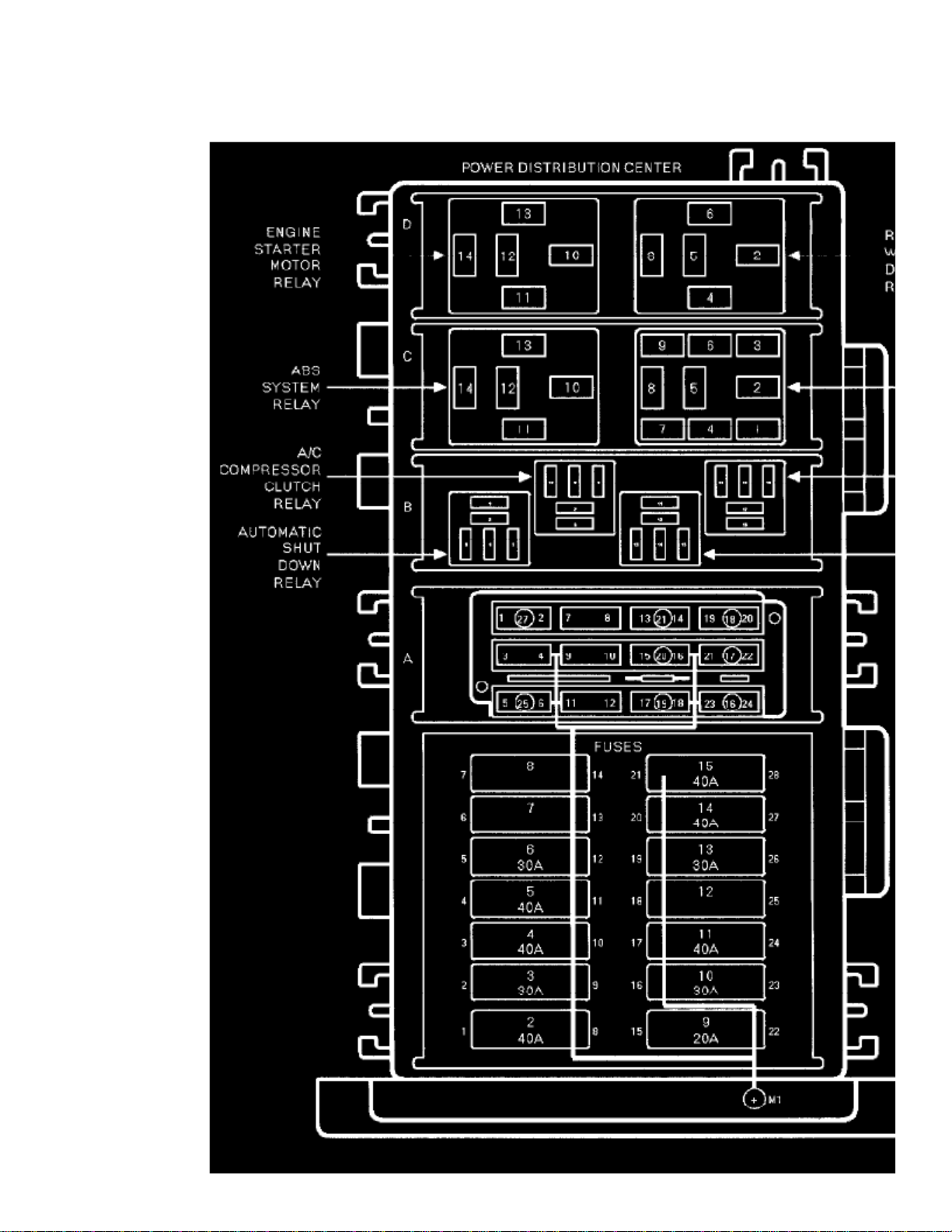
Power Distribution Center
ABS System Relay
Page 18

> Relays and Modules > Relays and Modules - Brakes and Traction Control > ABS Main Relay > Component Information > Locations > Page 17
ABS Main Relay: Description and Operation
RELAYS/SWITCHES
Relays: The ABS main relay is located in the power distribution center (PDC). The main relay has two function. First, when the relay is energized, itsupplies power to the valve/solenoids in the valve block assembly and the pump/motor relay coil. Second, when the relay is de-energized, it supplies aground to turn on the ABS warning indicator. The main relay is controlled by the CAB. The CAB energizes the main relay when it receives an ignitioninput signal.
The ABS pump/motor relay supplies power to the pump/motor, It is also located in the power distribution center (PDC). The relay coil is powered bythe main relay and the coil ground is controlled by the CAB. The pump/motor relay is a special five terminal relay and should not be replaced with astandard relay.
Page 19

Page 20

> Relays and Modules > Relays and Modules - Brakes and Traction Control > Brake Fluid Pump Relay > Component Information > Diagrams > ABS Pump/Motor Relay
Brake Fluid Pump Relay: DiagramsABS Pump/Motor Relay
Page 21

> Relays and Modules > Relays and Modules - Brakes and Traction Control > Brake Fluid Pump Relay > Component Information > Diagrams > ABS Pump/Motor Relay >
Page 22
Wrangler L4-2.5L VIN P (1999)
Power Distribution Center
Page 22

ABS Pump Motor Relay
Page 23

Page 24

> Relays and Modules > Relays and Modules - Brakes and Traction Control > Brake Fluid Pump Relay > Component Information > Diagrams > ABS Pump/Motor Relay > Page 23
Brake Fluid Pump Relay: DiagramsABS System Relays
Page 25

> Relays and Modules > Relays and Modules - Brakes and Traction Control > Brake Fluid Pump Relay > Component Information > Diagrams > ABS Pump/Motor Relay >
Page 24
Wrangler L4-2.5L VIN P (1999)
Power Distribution Center
Page 26

ABS System Relay
Page 27

Page 28

> Relays and Modules > Relays and Modules - Brakes and Traction Control > Electronic Brake Control Module > Component Information > Specifications
Electronic Brake Control Module: Specifications
Mounting Bolt ................................................................................................................................................................................. 7-9 Nm (60-80 inch lbs.)
Page 29

Page 30

> Relays and Modules > Relays and Modules - Brakes and Traction Control > Electronic Brake Control Module > Component Information > Specifications > Page 28
Electronic Brake Control Module: Locations
CONTROLLER ANTILOCK BRAKE
Controller Antilock Brake
The CAB is located under the instrument panel to the right side of the steering column. It is mounted to bracket with one bolt. The bracket is mounted tothe front upper cowl panel.
Page 31

Page 32

> Relays and Modules > Relays and Modules - Brakes and Traction Control > Electronic Brake Control Module > Component Information > Specifications > Page 29
Electronic Brake Control Module: Diagrams
Controller Anti-lock Brake C1 - Gray 12 Way
Controller Anti-lock Brake C2 Gray 18 Way
Page 33

Page 34

> Relays and Modules > Relays and Modules - Brakes and Traction Control > Electronic Brake Control Module > Component Information > Specifications > Page 30
Electronic Brake Control Module: Description and Operation
CONTROLLER ANTILOCK BRAKE (CAB)
The controller antilock brake (CAB) is a microprocessor-based device that monitors wheel speeds and controls the antilock functions.
The primary functions of the CAB are:
- monitor wheel speeds
- detect wheel locking tendencies
- control fluid pressure modulation to the brakes during antilock stop operation
- monitor the system for proper operation
- provide communication to the DRB III while in diagnostic mode
- store diagnostic information in non-volatile memory
The CAB continuously monitors the speed of each wheel. When a wheel locking tendency is detected, the CAB will command the appropriate valve tomodulate brake fluid pressure in its hydraulic unit. Brake pedal position is maintained during an antilock stop by being a closed system with the use of 3accumulators. The CAB continues to control pressure in individual hydraulic circuits until a wheel locking tendency is no longer present. The CAB turnson the pump/motor during an antilock stop.
The antilock brake system is constantly monitored by the CAB for proper operation. If the CAB detects a system malfunction, it can disable the antilocksystem and turn on the antilock warning indicator. If the antilock function is disabled, the system will revert to standard base brake system operation.
The CAB inputs include the following:
- four wheel speed sensors
- brake lamp switch
- ignition switch
- main relay output
- pump motor relay output
- battery voltage
- Diagnostic communication ISO/KY
- G switch (acceleration switch) The CAB outputs include the following:
six valve/solenoid driversMain relay actuation (Mark IVG only)
- pump/motor actuation
- ABS warning indicator actuation
- diagnostic communication
Page 35

Page 36

> Relays and Modules > Relays and Modules - Brakes and Traction Control > Electronic Brake Control Module > Component Information > Specifications > Page 31
Electronic Brake Control Module: Service and Repair
REMOVAL
1. Remove negative battery terminal.
Controller Antilock Brakes
2. Remove the harness connector from the CAB located underneath the instrument panel.3. Remove mounting bolt and remove the CAB.
INSTALLATION
7-9 Nm (60-80 inch lbs.)
1. Install the controller and install the mounting bolt.2. Tighten the mounting bolt to .3. Plug in the harness connector into the controller.4. Install negative battery cable.
Page 37

Page 38

> Relays and Modules > Relays and Modules - HVAC > Blower Motor Relay > Component Information > Locations
Blower Motor Relay: Locations
Blower Motor Relay Remove/Install
The blower motor relay is located in a wire harness connector that is secured to the heater- A/C housing behind the glove box on the passenger side ofthe vehicle, next to the heater-A/C wire harness connector in the passenger compartment.
Page 39

Page 40

> Relays and Modules > Relays and Modules - HVAC > Blower Motor Relay > Component Information > Locations > Page 36
Blower Motor Relay: Description and Operation
SYSTEM DESCRIPTION
(ISO)
The blower motor relay is a International Standards Organization -type relay. The relay is a electromechanical device that switches batterycurrent to the blower motor.
When the blower motor switch is in any position except off, and the ignition is turned on, the blower motor relay is energized and provides batteryfeed to the blower motor from a fuse in the fuseblock module through the blower motor resistor.
The blower motor relay coil is controlled by a voltage signal from the blower motor switch. See Blower Motor Relay in the Diagnosis and Testingfor more information.
The blower motor relay is installed in a wire harness connector located near the passenger side outboard end of the heater-A/C housing in thepassenger compartment, next to the heater-A/C wire harness connector.
The blower motor relay cannot be repaired and, if faulty or damaged, it must be replaced.
Page 41

Page 42

> Relays and Modules > Relays and Modules - HVAC > Blower Motor Relay > Component Information > Locations > Page 37
Blower Motor Relay: Testing and Inspection
Relay Test
Blower Motor Relay
The blower motor relay is located in a wire harness connector that is secured to the heater- A/C housing behind the glove box on the passenger side ofthe vehicle, next to the heater-A/C wire harness connector in the passenger compartment. Remove the relay from its connector to perform thefollowing tests:
1. A relay in the de-energized position should have continuity between terminals 87A and 30, and no continuity between terminals 87 and 30. If OK,
go to Step 2. If not OK, replace the faulty relay
75 5 ohms
2. Resistance between terminals 85 and 86 (electromagnet) should be . If OK, go to Step 3. If not OK, replace the faulty relay.3. Connect a battery to terminals 85 and 86. There should now be continuity between terminals 30 and 87, and no continuity between terminals 87A
and 30. If OK, see the Relay Circuit Test procedure. If not OK, replace the faulty relay.
Power Distribution Center (PDC) when the relay is energized, and ignition switched battery feed from a fuse in the fuseblock module through theblower motor resistor when the relay is de-energized. There should be continuity between this cavity and the blower motor feed circuit cavity ofthe blower motor wire harness connector at all times. If OK, go to Step 2. If not OK, repair the open circuit as required.
2. The relay normally closed terminal cavity (87A) is connected to the blower motor resistor output. When the relay is de-energized, terminal 87A is
connected to terminal 30 and provides the blower motor resistor output to the blower motor feed circuit. There should be continuity between thiscavity and the blower resistor outputs circuit cavity of the blower motor resistor wire harness connector at all times. If OK, go to Step 3. If not OK,repair the open circuit as required.
3. The relay normally open terminal cavity (87) is connected to a fused battery feed from the PDC. When the relay is energized, terminal 87 is
connected to terminal 30 and provides full battery current to the blower motor feed circuit. There should be battery voltage at this cavity at alltimes. If OK, go to Step 4. If not OK, repair the open circuit to the PDC as required.
4. The coil battery terminal cavity (86) is connected to the high speed output contacts of the blower motor switch. When the blower motor switch is
Page 43

1. The relay common feed terminal cavity (30) is connected to the blower motor. This terminal supplies fused battery feed directly from a fuse in theRelay Circuit Test
placed in the high speed position, fused ignition switch output is directed to the relay electromagnetic coil to energize the relay. There should becontinuity between the cavity for relay terminal 86 and the high blower motor relay control circuit cavity of the blower motor switch wire harnessconnector at all times. If OK, go to Step 5. If not OK, repair the open circuit as required.
5. The coil ground terminal cavity (85) is connected to ground. This terminal supplies tile ground for the relay electromagnet coil. There should be
continuity between the cavity for relay terminal 85 and a good ground at all times. If not OK, repair the open circuit as required.
Page 44

> Relays and Modules > Relays and Modules - HVAC > Blower Motor Relay > Component Information > Locations > Page 38
Blower Motor Relay: Service and Repair
REMOVAL
1. Disconnect and isolate the battery negative cable.2. Remove the glove box from the instrument panel. Refer to Glove Box in the Body and Frame/Interior Trim/Glove Compartment/Service and
Repair for the procedures.
Blower Motor Relay Remove/Install
3. Locate the blower motor relay through the instrument panel glove box opening. The relay is mounted upright and to the right of the instrument
panel harness.
4. Unplug the blower motor relay from its wire harness connector.
INSTALLATION
1. Install the blower motor relay by aligning the relay terminals with the cavities in the wire harness connector and pushing the relay firmly into
place.
2. Reinstall the glove box in the instrument panel. Refer to Glove Box in the Body and Frame/Interior Trim/Glove Compartment/Service and Repair
for the procedures.
3. Connect the battery negative cable.4. Test the relay operation.
Page 45

Page 46

> Relays and Modules > Relays and Modules - HVAC > Compressor Clutch Relay > Component Information > Locations > Component Locations
Compressor Clutch Relay: Component Locations
Page 47

8w-10-2
The compressor clutch relay is located in the Power Distribution Center in the engine compartment.(PDC)
Page 48

> Relays and Modules > Relays and Modules - HVAC > Compressor Clutch Relay > Component Information > Locations > Component Locations > Page 43
Compressor Clutch Relay: Connector Locations
Page 49

> Relays and Modules > Relays and Modules - HVAC > Compressor Clutch Relay > Component Information > Locations > Component Locations > Page 44
Wrangler L4-2.5L VIN P (1999)
Power Distribution Center
Page 50

A/C Compressor Clutch Relay
Page 51

Page 52

> Relays and Modules > Relays and Modules - HVAC > Compressor Clutch Relay > Component Information > Description and Operation > A/C Compressor Clutch Relay Description
Compressor Clutch Relay: Description and OperationA/C Compressor Clutch Relay Description
SYSTEM DESCRIPTION
(ISO)
The compressor clutch relay is a International Standards Organization micro-relay. The terminal designations and functions are the same asa conventional ISO relay However, the micro-relay terminal orientation (footprint) is different, the current capacity is lower, and the relay casedimensions are smaller than those of the conventional ISO relay.
(PCM)
The compressor clutch relay is a electromechanical device that switches battery current to the compressor clutch coil when the Powertrain ControlModule grounds the coil side of the relay The PCM responds to inputs from the heater-A/C mode control switch, the low pressure cyclingclutch switch, and the high pressure cut-off switch. See Compressor Clutch Relay in the Diagnosis and Testing for more information.
Power Distribution Center
(PDC)
The compressor clutch relay is located in the Power Distribution Center in the engine compartment. Refer to the PDC label for relayidentification and location.
The compressor clutch relay cannot be repaired and, if faulty or damaged, it must be replaced.
Page 53

Page 54

> Relays and Modules > Relays and Modules - HVAC > Compressor Clutch Relay > Component Information > Description and Operation > A/C Compressor Clutch Relay Description > Page 47
Compressor Clutch Relay: Description and OperationA/C Compressor Clutch Relay-PCM Output
AIR CONDITIONING (A/C) CLUTCH RELAY-PCM OUTPUT
The A/C relay is located in the Power Distribution Center (PDC). The PDC is located in the engine compartment. Refer to label on PDC cover forrelay location.
The powertrain control module (PCM) activates the A/C compressor through the A/C clutch relay. The PCM regulates A/C compressor operationby switching the ground circuit for the A/C clutch relay on and off.
When the PCM receives a request for A/C from A/C evaporator switch, it will adjust idle air control (IAC) motor position. This is done to increaseidle speed. The PCM will then activate the A/C clutch through the A/C clutch relay. The PCM adjusts idle air control (IAC) stepper motor positionto compensate for increased engine load from the A/C compressor.
By switching the ground path for the relay on and off, the PCM is able to cycle the A/C compressor clutch. This is based on changes in engineoperating conditions. The PCM Will also de-energize the relay if coolant temperature exceeds .125 C (257 F)
Page 55

Page 56

> Relays and Modules > Relays and Modules - HVAC > Compressor Clutch Relay > Component Information > Description and Operation > Page 48
Compressor Clutch Relay: Testing and Inspection
Relay Test
Compressor Clutch Relay
The compressor clutch relay is located in the Power Distribution Center (PDC). Refer to the PDC label for relay identification and location. Removethe relay from the PDC to perform the following tests:1. A relay in the de-energized position should have continuity between terminals 87A and 30, and no continuity between terminals 87 and 30. If OK,
go to Step 2. If not OK, replace the faulty relay
75 5 ohms
2. Resistance between terminals 85 and 86 (electromagnet) should be . If OK, go to Step 3. If not OK, replace the faulty relay.3. Connect a battery to terminals 85 and 86. There should now be continuity between terminals 30 and 87, and no continuity between terminals 87A
and 30. If OK, see Relay Circuit Test in the Diagnosis and Testing. If not OK, replace the faulty relay.
Relay Circuit Test
1. The relay common feed terminal cavity (30) is connected to fused battery feed. There should be battery voltage at the cavity for relay terminal 30
at all ,times. If OK, go to Step 2. If not OK, repair the open circuit to the fuse in the PDC as required.
2. The relay normally closed terminal (87A) is not used in this application. Go to Step 3.3. The relay normally open terminal cavity (87) is connected to the compressor clutch coil. There should be continuity between this cavity and the
A/C compressor clutch relay output circuit cavity of the compressor clutch coil wire harness connector. If OK, go to Step 4. If not OK, repair theopen circuit as required.
4. The relay coil battery terminal (86) is connected to the fused ignition switch output (run/start) circuit. There should be battery voltage at the cavity
for relay terminal 86 with the ignition switch in the On position. If OK, go to Step 5. If not OK, repair the open circuit to the fuse in the junctionblock as required.
5. The coil ground terminal cavity (85) is switched to ground through the Powertrain Control Module (PCM). There should be continuity between
this cavity and the A/C compressor clutch relay control circuit cavity of the PCM wire harness connector C (gray) at all times. If not OK, repair theopen circuit as required.
Page 57

Page 58

> Relays and Modules > Relays and Modules - HVAC > Compressor Clutch Relay > Component Information > Description and Operation > Page 49
Compressor Clutch Relay: Service and Repair
REMOVAL AND INSTALLATION
1. Disconnect and isolate the battery negative cable.
Power Distribution Center
2. Remove the cover from the Power Distribution Center (PDC).3. Refer to the label on the PDC for compressor clutch relay identification and location.4. Unplug the compressor clutch relay from the PDC.5. Install the compressor clutch relay by aligning the relay terminals with the cavities in the PDC and pushing the relay firmly into place.6. Install the PDC cover.7. Connect the battery negative cable.8. Test the relay operation.
Page 59

Page 60

> Relays and Modules > Relays and Modules - HVAC > Control Module HVAC > Component Information > Service Precautions
Control Module HVAC: Service Precautions
WARNING: ON VEHICLES EQUIPPED WITH AIRBAGS, REFER TO RESTRAINT SYSTEMS / AIRBAG SYSTEMS BEFOREATTEMPTING ANY STEERING WHEEL, STEERING COLUMN, OR INSTRUMENT PANEL COMPONENT DIAGNOSIS OR SERVICE.FAILURE TO TAKE THE PROPER PRECAUTIONS COULD RESULT IN ACCIDENTAL AIRBAG DEPLOYMENT AND POSSIBLEPERSONAL INJURY
.
Page 61

Page 62

> Relays and Modules > Relays and Modules - Instrument Panel > Cigarette Lighter Relay > Component Information > Locations
Cigarette Lighter Relay: Locations
Accessory Relay Remove/Install
The accessory relay is located in a wire harness connector that is secured to the 100-way connector bracket under the driver side of the instrument panel,near the cowl side inner panel in the passenger compartment.
Page 63

Page 64

> Relays and Modules > Relays and Modules - Instrument Panel > Cigarette Lighter Relay > Component Information > Locations > Page 57
Cigarette Lighter Relay: Service Precautions
WARNING: ON VEHICLES EQUIPPED WITH AIRBAGS, REFER TO RESTRAINT SYSTEMS / AIRBAG SYSTEMS BEFOREATTEMPTING ANY STEERING WHEEL, STEERING COLUMN, OR INSTRUMENT PANEL COMPONENT DIAGNOSIS OR SERVICE.FAILURE TO TAKE THE PROPER PRECAUTIONS COULD RESULT IN ACCIDENTAL AIRBAG DEPLOYMENT AND POSSIBLEPERSONAL INJURY
.
Page 65

Page 66

> Relays and Modules > Relays and Modules - Instrument Panel > Cigarette Lighter Relay > Component Information > Locations > Page 58
Cigarette Lighter Relay: Description and Operation
DESCRIPTION
The accessory relay is an electromechanical device that switches fused battery current to the standard accessory power outlet or optional cigarlighter when the ignition switch is turned to the Accessory or On positions. The accessory relay is located in a wire harness connector that issecured to the 100-way connector bracket under the driver side of the instrument panel, near the cowl side inner panel in the passengercompartment.
(ISO)
The accessory relay is a International Standards Organization relay. Relays conforming to the ISO specifications have common physicaldimensions, current capacities, terminal patterns, and terminal functions.
The accessory relay cannot be repaired or adjusted and, if faulty or damaged, it must be replaced.
OPERATION
The ISO relay consists of an electromagnetic coil, a resistor or diode, and three (two fixed and one movable) electrical contacts. The movable(common feed) relay contact is held against one of the fixed contacts (normally closed) by spring pressure. When the electromagnetic coil isenergized, it draws the movable contact away from the normally closed fixed contact, and holds it against the other (normally open) fixed contact.
When the electromagnetic coil is de-energized, spring pressure returns the movable contact to the normally closed position. The resistor or diode isconnected in parallel with the electromagnetic coil in the relay, and helps to dissipate voltage spikes that are produced when the coil isde-energized.
Page 67

Page 68

> Relays and Modules > Relays and Modules - Instrument Panel > Cigarette Lighter Relay > Component Information > Locations > Page 59
Cigarette Lighter Relay: Testing and Inspection
Accessory Relay
The accessory relay is located in a wire harness connector that is secured to the 100-way connector bracket under the driver side of the instrument panel,near the cowl side inner panel in the passenger compartment.
1. Remove the accessory relay from its wire harness connector. Refer to Accessory Relay/Service and Repair for the procedures. 2. A relay in the de-energized position should have continuity between terminals 87A and 30, and no continuity between terminals 87 and 30. If OK,
go to Step 3. If not OK, replace the faulty relay.
75 5 ohms
3. Resistance between terminals 85 and 86 (electromagnet) should be . If OK, go to Step 4. If not OK, replace the faulty relay. 4. Connect a battery to terminals 85 and 86. There should now be continuity between terminals 30 and 87, and no continuity between terminals 87A
and 30. If OK, perform the Relay Circuit Test that follows. If not OK, replace the faulty relay
1. The relay common feed terminal (30) is connected to battery voltage and should be hot at all times. Check for battery voltage at the fused B(+)Relay Circuit Test
circuit cavity of the accessory relay wire harness connector. If OK, go to Step 2. If not OK, repair the fused B(+) circuit to the fuse in the PowerDistribution Center (PDC) as required.
2. The relay normally closed terminal (87A) is connected to terminal 30 in the de-energized position, but is not used for this application. Go to Step
3.
3. The relay normally open terminal (87) is connected to the common feed terminal (30) in the energized position. This terminal supplies battery
voltage to the cigar lighter or power outlet when the relay is energized by the ignition switch. There should be continuity between the accessoryrelay wire harness connector cavity for relay terminal 87 and the accessory relay output circuit cavity in the cigar lighter or power outlet wireharness connector at all times. If OK, go to Step 4. If not OK, repair the open accessory relay output circuit to the cigar lighter or power outletwire harness connector as required.
4. The coil battery terminal (86) is connected to the electromagnet in the relay. The accessory relay wire harness connector cavity for this terminal
should have continuity to ground at all times. If OK, go to Step 5. If not OK, repair the open ground circuit to ground as required.
5. The coil ground terminal (85) is connected to the electromagnet in the relay. It receives battery feed to energize the accessory relay when the
ignition switch is in the Accessory or On positions. Turn the ignition switch to the On position. Check for battery voltage at the fused ignitionswitch output (acc/run) circuit cavity of the accessory relay wire harness connector. If not OK, repair the open fused ignition switch output(acc/run) circuit to the ignition switch as required.
Page 69

Page 70

> Relays and Modules > Relays and Modules - Instrument Panel > Cigarette Lighter Relay > Component Information > Locations > Page 60
Cigarette Lighter Relay: Service and Repair
REMOVAL
1. Disconnect and isolate the battery negative cable.
Accessory Relay Remove/Install
2. Reach up under the instrument panel outboard of the steering column to access the accessory relay and the accessory relay wire harness connector,
which is secured to the 100-way wire harness connector mounting bracket.
3. Disconnect the accessory relay from the accessory relay wire harness connector. 4. Remove the accessory relay from under the instrument panel.
INSTALLATION
1. Position the accessory relay to the accessory relay wire harness connector under the instrument panel. 2. Align the terminals of the accessory relay with the cavities in the accessory relay wire harness connector. 3. Push on the accessory relay case firmly and evenly until all of the relay terminals are fully seated within the cavities of the accessory relay wire
harness connector.
4. Reconnect the battery negative cable.
Page 71

Page 72

> Relays and Modules > Relays and Modules - Lighting and Horns > Daytime Running Lamp Control Unit > Component Information > Locations
DRL Module
Page 73

Page 74

> Relays and Modules > Relays and Modules - Lighting and Horns > Daytime Running Lamp Control Unit > Component Information > Locations > Page 65
Daytime Running Lamp Control Unit: Service and Repair
REMOVAL
1. Disconnect the wire harness connector from the module.
DRL Module
2. Remove the screws that attach the module to the cowl. 3. Separate the module from the vehicle.
INSTALLATION
1. Position the DRL module on the cowl. 2. Install the screws. 3. Connect the wire harness connector to the module.
Page 75

Page 76

> Relays and Modules > Relays and Modules - Lighting and Horns > Horn Relay > Component Information > Locations
Horn Relay: Locations
Page 77

8w-10-2
The horn relay is located in the Power Distribution Center in the engine compartment.(PDC)
Page 78
> Relays and Modules > Relays and Modules - Lighting and Horns > Horn Relay > Component Information > Locations > Page 69
Horn Relay: Diagrams
Page 79

Power Distribution Center
Horn Relay
Page 80

> Relays and Modules > Relays and Modules - Lighting and Horns > Horn Relay > Component Information > Locations > Page 70
Horn Relay: Service Precautions
WARNING: ON VEHICLES EQUIPPED WITH AIRBAGS, REFER TO RESTRAINT SYSTEMS / AIRBAG SYSTEMS BEFOREATTEMPTING ANY STEERING WHEEL, STEERING COLUMN, OR INSTRUMENT PANEL COMPONENT DIAGNOSIS OR SERVICE.FAILURE TO TAKE THE PROPER PRECAUTIONS COULD RESULT IN ACCIDENTAL AIRBAG DEPLOYMENT AND POSSIBLEPERSONAL INJURY
.
Page 81

Page 82

> Relays and Modules > Relays and Modules - Lighting and Horns > Horn Relay > Component Information > Locations > Page 71
Horn Relay: Description and Operation
DESCRIPTION
(PDC)
The horn relay is a electromechanical device that switches battery current to the horn when the horn switch grounds the relay coil. The horn relayis located in the Power Distribution Center in the engine compartment. If a problem is encountered with a continuously sounding horn, itcan usually be quickly resolved by removing the horn relay from the PDC until further diagnosis is completed. See the fuse and relay layout labelaffixed to the inside surface of the PDC cover for horn relay identification and location.
(ISO)
The horn relay is a International Standards Organization micro-relay. Relays conforming to the ISO specifications have common physicaldimensions, current capacities, terminal patterns, and terminal functions. The ISO micro-relay terminal functions are the same as a conventionalISO relay. However, the ISO micro-relay terminal pattern (or footprint) is different, the current capacity is lower, and the physical dimensions aresmaller than those of the conventional ISO relay
The horn relay cannot be repaired or adjusted and, if faulty or damaged, it must be replaced.
OPERATION
The ISO relay consists of an electromagnetic coil, a resistor or diode, and three (two fixed and one movable) electrical contacts. The movable(common feed) relay contact is held against one of the fixed contacts (normally closed) by spring pressure. When the electromagnetic coil isenergized, it draws the movable contact away from the normally closed fixed contact, and holds it against the other (normally open) fixed contact.
When the electromagnetic coil is de-energized, spring pressure returns the movable contact to the normally closed position. The resistor or diode isconnected in parallel with the electromagnetic coil in the relay, and helps to dissipate voltage spikes that are produced when the coil isde-energized.
Page 83

Page 84

> Relays and Modules > Relays and Modules - Lighting and Horns > Horn Relay > Component Information > Locations > Page 72
Horn Relay: Testing and Inspection
Horn Relay
The horn relay is located in the Power Distribution Center (PDC) behind the battery on the driver side of the engine compartment. If a problem isencountered with a continuously sounding horn, it can usually be quickly resolved by removing the horn relay from the PDC until further diagnosis iscompleted. See the fuse and relay layout label affixed to the inside surface of the PDC cover for horn relay identification and location.
1. Remove the horn relay from the PDC. Refer to Horn Relay/Service and Repair for the procedures. 2. A relay in the de-energized position should have continuity between terminals 87A and 30, and no continuity between terminals 87 and 30. If OK,
go to Step 3. If not OK, replace the faulty relay.
75 5 ohms
3. Resistance between terminals 85 and 86 (electromagnet) should be . If OK, go to Step 4. If not OK, replace the faulty relay 4. Connect a battery to terminals 85 and 86. There should now be continuity between terminals 30 and 87, and no continuity between terminals 87A
and 30. If OK, perform the Relay Circuit Test that follows. If not OK, replace the faulty relay.
1. The relay common feed terminal cavity (30) is connected to battery voltage and should be hot at all times. If OK, go to Step 2. If not OK, repairRelay Circuit Test
the open circuit to the fuse in the PDC as required.
2. The relay normally closed terminal (87A) is connected to terminal 30 in the de-energized position, but is not used for this application. Go to Step
3.
3. The relay normally open terminal (87) is connected to the common feed terminal (30) in the energized position. This terminal supplies battery
voltage to the horn(s). There should be continuity between the cavity for relay terminal 87 and the horn relay output circuit cavity of each hornwire harness connector at all times. If OK, go to Step 4. If not OK, repair the open circuit to the horn(s) as required.
4. The coil battery terminal (86) is connected to the electromagnet in the relay It is connected to battery voltage and should be hot at all times. Check
for battery voltage at the cavity for relay terminal 86. If OK, go to Step 5. If not OK, repair the open circuit to the fuse in the PDC as required.
5. The coil ground terminal (85) is connected to the electromagnet in the relay It is grounded through the horn switch when the horn switch is
depressed. Check for continuity to ground at the cavity for relay terminal 85. There should be continuity with the horn switch depressed, and nocontinuity with the horn switch released. If not OK, refer to Horn Switch in the Diagnosis and Testing of procedures.
Page 85

Page 86

> Relays and Modules > Relays and Modules - Lighting and Horns > Horn Relay > Component Information > Locations > Page 73
Horn Relay: Service and Repair
REMOVAL
1. Disconnect and isolate the battery negative cable.
Power Distribution Center
2. Remove the cover from the Power Distribution Center (PDC). 3. See the fuse and relay layout label affixed to the underside of the PDC cover for horn relay identification and location. 4. Remove the horn relay from the PDC.
INSTALLATION
1. See the fuse and relay layout label affixed to the underside of the PDC cover for the proper horn relay location. 2. Position the horn relay in the proper receptacle in the PDC. 3. Align the horn relay terminals with the terminal cavities in the PDC receptacle. 4. Push down firmly on the horn relay until the terminals are fully seated in the terminal cavities in the PDC receptacle. 5. Install the cover onto the PDC. 6. Reconnect the battery negative cable.
Page 87

Page 88

> Relays and Modules > Relays and Modules - Powertrain Management > Relays and Modules - Computers and Control Systems > Body Control Module > Component Information > Service Precautions > Technician Safety
Information
Body Control Module: Technician Safety Information
ROAD TESTING A COMPLAINT VEHICLE
Some complaints will require a test drive as part of the repair verification procedure. The purpose of the test drive is to try to duplicate thediagnostic code or symptom condition.
CAUTION:
BEFORE ROAD TESTING A VEHICLE, BE SURE THAT ALL COMPONENTS ARE REASSEMBLED. DURING THE TESTDRIVE, DO NOT TRY TO READ THE DRB SCREEN WHILE IN MOTION. DO NOT HANG THE DRB FROM THE REAR VIEWMIRROR OR OPERATE IT YOURSELF. HAVE AN ASSISTANT AVAILABLE TO OPERATE THE DRB.
Page 89

Page 90

> Relays and Modules > Relays and Modules - Powertrain Management > Relays and Modules - Computers and Control Systems > Body Control Module > Component Information > Service Precautions > Technician Safety
Information > Page 80
Body Control Module: Vehicle Damage Warnings
VEHICLE DAMAGE WARNINGS
Before disconnecting any control module, make sure the ignition is "OFF". Failure to do so could damage the module.
When testing voltage or continuity at any control module, use the terminal side (not the wire end) of the connector. Do not probe a wire throughthe insulation; this will damage it and eventually cause it to fail because of corrosion.
Be careful when performing electrical tests so as to prevent accidental shorting of terminals. Such mistakes can damage fuses or components. Also,a second code could be set, making diagnosis of the original problem more difficult.
When replacing a blown fuse, it is important to use only a fuse having the correct amperage rating. The use of a fuse with a rating other thanindicated may result in a dangerous electrical system overload. If a properly rated fuse continues to blow, it indicates a problem in the circuit thatmust be corrected.
Service and general information labels about the airbag system can be found on the driver's sun visor, the glove box door, and in the enginecompartment.
To ensure that the airbag will be ready to deploy in a collision, have the system serviced by an authorized dealer.
Page 91

Page 92

> Relays and Modules > Relays and Modules - Powertrain Management > Relays and Modules - Computers and Control Systems > Body Control Module > Component Information > Service Precautions > Page 81
Body Control Module: Application and ID
GLOSSARY OF TERMS
ACM
Airbag Control Module
AECM
Airbag Electronic Control Module
Airbag Module
also called "squib" initiator. It is located inside the driver side airbag module assembly.
ASCM
Airbag System Diagnostic System
CCD
Chrysler Collision Detection (vehicle communication bus)
DAB
Driver Airbag
PAB
Passenger Airbag
DLC
Data Link Connector
PCM
Powertrain Control Module
PDC
Power Distribution Center
SKIM
Sentry Key Immobilizer Module
SKIS
Sentry Key Immobilizer System
Page 93

Page 94

> Relays and Modules > Relays and Modules - Powertrain Management > Relays and Modules - Computers and Control Systems > Body Control Module > Component Information > Description and Operation > Airbag System
Body Control Module: Description and OperationAirbag System
AIRBAG SYSTEM
(ACM)
The airbag system is designed to provide increased driver and passenger protection if the vehicle is involved in a front-end collision. The system isdesigned to be used in conjuction with the seat belt system. Currently, Chrysler Corporation uses two types of Airbag Control Modules .The ASDM system is a mechanically-triggered system utilizing two front impact sensors and a sensor inside the module. The AECM is anelectronically-triggered system that uses only its own internal electronic sensor to trigger the airbags. The TJ Body uses only the AECM system.
6 8 seconds
Whenever the ignition key is turned to the RUN or START position, the Airbag Control Module (ACM) performs a lamp check by turning theAIRBAG warning lamp on. The lamp stays lit for to , then goes OFF. If the lamp remains OFF, it means the ACM has checked thesystem and found it to be free of discernable malfunctions. The airbag system is monitored by the ACM.
The ACM monitors critical input and output circuits within the airbag system, making sure they are operating correctly. Some circuits are testedcontinuously; others are checked only under certain circumstances. The ACM provides diagnostic information about the airbag system to thetechnician through the DRB via the CCD bus.
The AIRBAG warning lamp is the only point at which "symptoms" of a system malfunction can be observed by the customer.
The deceleration or g-force resulting from the impact of a front-end collision causes the electronic sensor inside of the ACM to be triggered. Thiscauses the inflators to be actuated, thus deploying the airbags. The total time between determining to deploy and deflation of the airbag is of a second.1/10th
1999 Wranglers will be equipped with a passenger airbag ON/OFF switch. This switch has an LED that will light when the switch is in the "OFF"position. While in the "OFF" position a circuit board inside the switch will simulate a passenger airbag to prevent the ACM from logging a DTC.However it is important that the ignition be in the OFF before moving the ON/OFF switch to the OFF or ON position, otherwise the ACM may loga DTC and turn on the airbag warning lamp due to a momentary open of the switch contacts.
Use the test procedures in this book to find the cause of any customer complaint regarding the AIRBAG warning lamp such as:-
warning lamp does not come on at all
- warning lamp stays ON
AIRBAG DIAGNOSTIC TROUBLE CODES
Airbag diagnostic trouble codes consist of active and stored codes. If more than one exists, diagnostic priority should be given to the activecode(s).
Each diagnostic trouble code is diagnosed by following a specific testing procedure. The diagnostic test procedures contain step-by-stepinstructions for determining the cause of the trouble codes. It is necessary to perform all of the tests in this book to diagnose an individual code.
Active diagnostic trouble codes for the airbag system are not permanent and will change the moment the reason for the code is corrected. In certaintest procedures, diagnostic trouble codes are used as a diagnostic tool.
Active Codes
An active trouble code indicates an on-going malfunction. This means that the defect is currently there every time the airbag control modulechecks that circuit/function. It is impossible to erase an active code; active codes automatically erase themselves when the reason for the code hasbeen corrected.
With the exception of the warning lamp trouble codes or malfunctions, when a malfunction is detected, the AIRBAG lamp remains lit for aminimum of or as long as the malfunction is present.12 seconds
Page 95

> Relays and Modules > Relays and Modules - Powertrain Management > Relays and Modules - Computers and Control Systems > Body Control Module > Component
Information > Description and Operation > Airbag System > Page 84
Wrangler L4-2.5L VIN P (1999)
Always begin by reading the diagnostic trouble codes using the DRB. If more than one code exists, diagnostic priority should be given to theactive code(s).
Stored Codes
Airbag codes are automatically stored in the ACM's memory when the ignition is turned OFF with the exception of the Loss of Ignition Run Onlycode, which is an active code only.
A "stored" code indicates there was an active code present at some time. However, the code currently may not be present as an active code,although another active code could be.
12 seconds
12seconds in minutes
When a trouble code occurs, the AIRBAG warning lamp illuminates for minimum (even if the problem existed for less than ). The code is stored, along with the time it was active, and the number of times the ignition has been cycled since the problemwas last detected.
The minimum time shown for any code will be one minute, even if the code was actually present for less than one minute. Thus, the time shownfor a code that was present for , for example, would be .two minutes 13 seconds three minutes
Page 96

If a malfunction is not active while performing a diagnostic test procedure, the active code diagnostic test will not locate the source of the problem.In this case, the stored code can indicate an area to inspect.
If no obvious problems are found, erase stored codes, and with the ignition "ON", wiggle the wire harness and connectors, rotate the steeringwheel from stop to stop. Recheck for codes periodically as you work through the system. This procedure may uncover a malfunction that isdifficult to locate.
Airbag Trouble Codes
The Airbag Control Module may report any of the following diagnostic trouble codes.
For the following ACTIVE OR STORED codes, replace the Airbag Control Module (ACM) even if set intermittently:
- AECM Accelerometer
- Internal Diagnostic 1
- AECM Output Driver
- AECM Stored Energy Logic
- AECM Stored Energy Driver
- AECM Stored Energy Passenger
- Internal Diagnostic 2
- Internal Diagnostic 3
- Internal Diagnostic 4
- Safing Sensor Shorted
For these codes, refer to the appropriate diagnostic procedure:
- Driver Squib Circuit Open
- Driver Squib Circuit Shorted
- Loss of Ignition Run Only
- Loss of Ignition to Run/Start
- No Cluster CCD Bus Message
- No CCD Communication
- Passenger Squib Circuit Shorted
- Passenger Squib Circuit Open
- Either Squib Term Shorted to Battery
- Either Squib Term Short to Ground
- Warning Lamp Circuit Open/Shorted
Page 97

Page 98

> Relays and Modules > Relays and Modules - Powertrain Management > Relays and Modules - Computers and Control Systems > Body Control Module > Component Information > Description and Operation > Airbag System
> Page 85
Body Control Module: Description and OperationDRB III Error Messages and Blank Screen
DRB III ERROR MESSAGES AND BLANK SCREEN
Under normal operation, the DRB will display one of only two error messages:-
User-Requested WARM Boot or
- User-Requested COLD Boot
If the DRB should display any other error message, record the entire display and call the MDS Hotline, or call for information and assistance at1-800-825-8737. This is a sample of such an error message display:
ver: 2.14date: 26 Jul 93file: key_itf.ccdate: Jul 26 1993line: 548err: Ox1User-Requested COLD Boot
Press MORE to switch between this display and the application screen.Press F4 when done noting information.
DRB III Does Not Power Up
If the LED's do not light or no sound is emitted at start up, check for loose cable connections or a bad cable. Check the vehicle battery voltage(data link connector cavity 16). A minimum of is required to adequately power the DRB.11 volts
If all connections are proper between the DRB and the vehicle or other devices, and the vehicle battery is fully charged, and inoperative DRB maybe the result of faulty cable or vehicle wiring. Perform Vehicle Communication TEST 1A.
DRB III Scan Tool
Display Is Not Vivible
Low temperatures will affect the visibility of the display. Adjust the contrast to compensate for this condition.
Page 99

Page 100

> Relays and Modules > Relays and Modules - Powertrain Management > Relays and Modules - Computers and Control Systems > Body Control Module > Component Information > Description and Operation > Airbag System
> Page 86
Body Control Module: Description and OperationInstrument Cluster
INSTRUMENT CLUSTER
(VFD)
The instrument cluster used in the Jeep Wrangler contains six gauges and eleven warning lamps. The gauges are positioned with informationreceived by the cluster over the CCD bus from the PCM. Some of the lamps are hardwired and some are controlled by the cluster using CCD businformation. The vehicle chime function is contained on the cluster circuit board as well as the timer for the rear window defogger. There is a selftest available for the cluster that will actuate all the gauges and place them at their calibration points. The test will not run if the cluster sees engineRPM or vehicle speed. This test will light all CCD controlled lamps for verification of lamp operation. It also forces the odometer vacuumfluorescent display to count up from zero through nine. The self test routine can be entered by pushing and holding the trip reset buttonwhile rotating the ignition key from the "OFF" to the "ON" position.
The 1999 TJ cluster provides bus bias and the engine controller provides termination. If either of these components are disconnected, the bus willnot be operational. Starting in 1998, the cluster also provides termination as a backup to the engine controller.
The cluster will be serviced as an assembly. There will be limited parts available, bulbs and sockets, the front lens, the trip odometer stem coverand the rear cover assembly. No internal parts of the cluster will be serviced.
Engine Temp Critical
Oil Pressure Low 6 psi 300 RPM
Volt Gauge Low
- when gauge reaches the high end of the red zone. - below and above . - when engine controller sets the "charge fail" DTC. - when engine controller sets the "voltage high" DTC.Volt Gauge High
Normal Operation:
At key ON, the cluster will light the low fuel, seat belt, check gauges, airbag and/or smart key immobilizer and upshift lamps(if equipped). As the key is turned farther towards the start position, the ABS (if equipped) and brake warning lamp will illuminate. The vacuumfluorescent (VF) display will indicate the last selected mode, odometer or trip. If there is a bus failure and the cluster cannot receive distancepulses from the PCM, the cluster will display the last mileage stored until the ignition is turned OFF. If the cluster is receiving bus messages but isunable to display odometer information because of an internal failure, the odometer will display dashes. VF dimming is handled by thepotentiometer that controls instrumentation illumination. The odometer will remain in the last mode selected, trip or vehicle mileage after each keycycle.
Rear Window Defogger
10 minute 10 minutes
5 minutes
The timing circuit for the rear window defogger is contained in the cluster. The operation is as follows:With ignition ON, the first push of the defogger button will start a timer. After have elapsed, the defogger will be turnedOFF. If the button is pushed a second time during the same ignition cycle, the timer will turn the defogger on for . Every consecutivepush will operate the defogger for . When the defogger is ON, it can be turned OFF with a second push of the defogger button.5 minutes
Chime
Seat Belt Warning 6 seconds
Key In Ignition Warning
- after key on - door open with key in ignition - when gauge enters red zoneEngine Temp High
Lamps (Hardwired)
The following lamps are hardwired in the cluster and are not part of the self-test.
 Loading...