

Page 1

Jeep Wrangler
Diagnosis & Repair Manual
Water Leaks
Rev. A
Page 2
General Notes
1. This manual applies to all Jeep models: 2/4 door & Hard/Soft Top
2. Before testing the vehicle, perform a review of the top system. Make sure all the latches
are engaged, none of the top seals are puckered or distorted, the door seals are
installed correctly, the tops are not out of alignment, etc.
3. Each leak area can have multiple root causes, as noted in the diagnosis tree. It is
important to water test each repair before starting the next.
4. If a leak cannot be reproduced, it is due to the period of time the vehicle is under wet
conditions. Some leaks may take hours before leaking.
5. If a leak cannot be reproduced, apply all the repairs to the applicable areas as noted in
the diagnosis road map.
6. When the door is open, there is water run off from the roof that can soak the carpet. Be
sure to explain to the customer that this cannot be fixed. This is an unfortunate
condition with this type of vehicle, similar to convertibles.
7. It is important to understand where the leak ENDS up when diagnosing the vehicle.
Where the leak ends up, does not always explain where the leak originates. Refer to the
diagnosis tree when determining which repairs to perform.
8. This repair procedure does NOT cover every possible water leak on the Jeep Wrangler.
The issues identified in this document are the major leaks that show up in the field.
9. Generally, a car wash is the preferred method to diagnose a vehicle.
10. If a hose is required, place on the top of the vehicle facing forward making sure water is
getting to all areas. Do NOT directly spray in the area of question. This can create a
“false” leak that cannot be fixed.
11. This manual is not intended to be a service manual. The content identifies the major
areas of water leaks, the critical characteristics of each area and how to repair them.
READ FIRST READ FIRST
i
Page 3
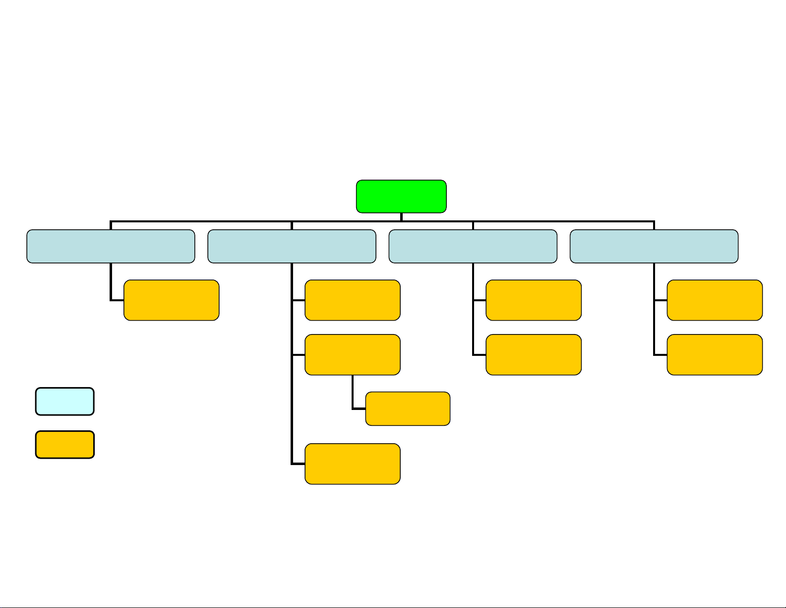
Diagnosis Road Map
p
r
(Pag
JK Hard/Soft Top
Water is on center of Instrument
Panel / Shifter
Freedom Top
(Pages 6-11)
Area of leaks
Repair Procedures
Water is on door trim panel or
Instrument Panel at A-pillar
Windshield Header
Seal
(Pages 1-2)
Door Fit
(Page 3)
A-Pillar
Mucket/Foam
(Pages 4-5)
Water at Rear Hard Top Panel /
B-
illa
Door Primary
Seal
Hard Top Seal
(Pages 12-14)
B-Pillar
Mucket/Foam
-
Water is on front carpet
Rear Wheel Flare
Holes
es 17-18)
Cowl Side Panel
(Pages 19-20)
ii
Page 4

Table of Contents
I. Diagnosis Road Map i
II. General Notes ii
III. Water leak on Door Trim or Instrument Panel
a) Repair procedure for Windshield Header Seal 1-2
b) Repair procedure for Door Fits 3
c) Repair procedure for A-pillar mucket/foam 4-5
IV. Water leak on Instrument Panel/Console Center
a) Repair procedure for Freedom Panel Seal 6-11
b) Repair procedure for Freedom Panel latches 11
V. Water leak at B-plr
a) Repair procedure for Hard Top Seal 12-14
b) Repair procedure for B-pillar Mucket 15-16
VI. Water leak on front carpet
a) Repair procedure for rear wheel flare hole 17-18
b) Repair procedure for cowl side leaks 19-20
VII. Appendix
a) Foam Kit 21
b) Replacement part numbers 22
iii
Page 5
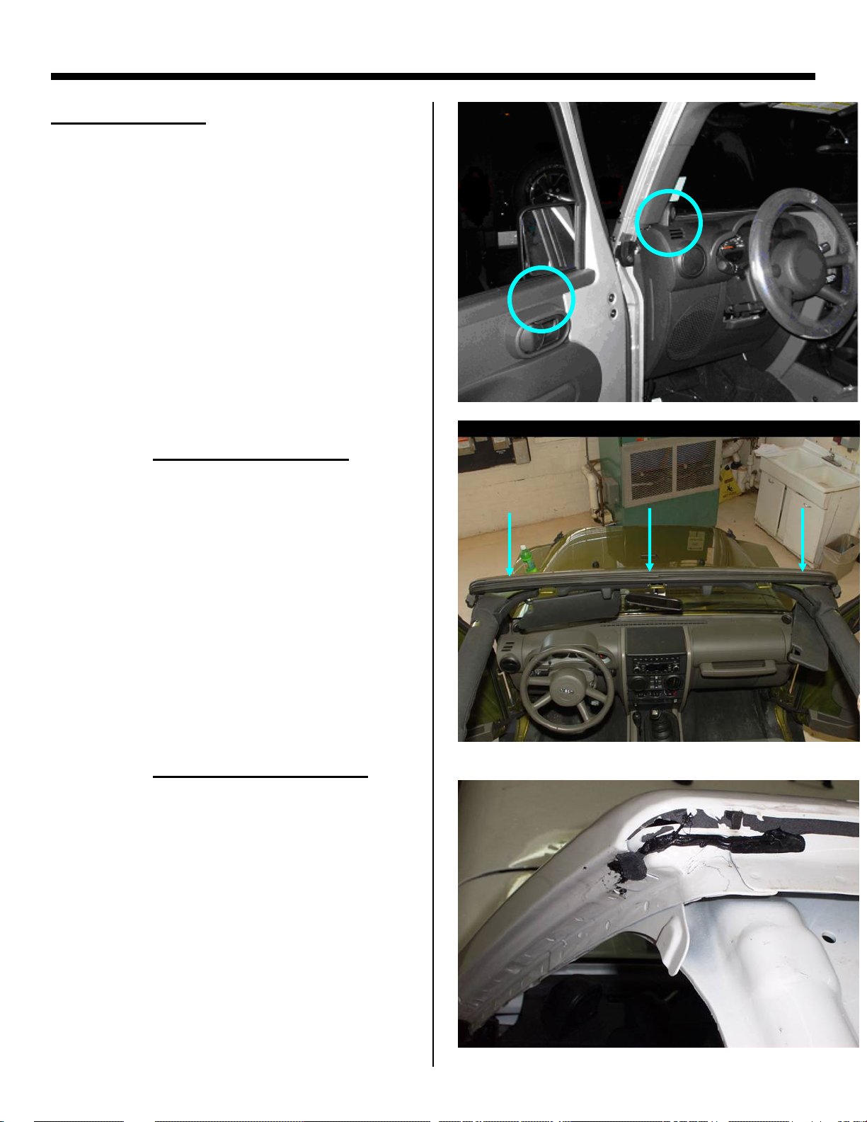
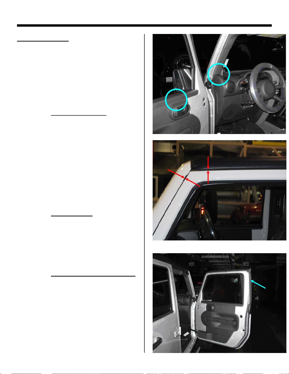
Windshield Header Seal Repair Procedure
AREA OF LEAK:
• This repair procedure is applicable
when water is evident on the:
o Door trim panel
or
o Instrument panel (a-pillar)
STEP 1: Remove Header Seal
• Figure 1
STEP 2: Remove/Clean Surface
• Remove all butyl and tape residue
• A rubber wheel bit can be used
• Clean surface with 3M adhesive
cleaner
• Alcohol wipe entire surface and allow
to dry
Labor Op. Code: 235135
Figure 1
Figure 2
1
Page 6
Windshield Header Seal Repair Procedure
STEP 3: Install Butyl
• NOTE: This operation is only
applicable for vehicles built before
6/1/2008. Vehicles built after this
date, should already have sealer
present in this area.
• Install 4mm butyl (68027813AA) as
shown (Figure 4)
• Make sure to fill in all holes, wrinkles
and step offs to allow for a smooth
surface to bond the tape/butyl from
the new seal
• NOTE: Excessive amount of butyl
can cause transition voids/leaks.
Make sure to smooth out butyl.
STEP 4: Install Seal
• Locate and install new seal, Pt #:
55397454AE
• Remove release tape and pressurize
seal firmly in contact with header
sheet metal to smooth out adhesive
tape and butyl, starting at the ends
and working toward the center. A
small roller or firm finger pressure
should be used to insure the tape is
adhered completely from side to side,
THIS STEP IS CRITICAL
Where to
place butyl
Figure 3
Butyl
Figure 4
Line seal
up here
Labor Op. Code: 235135
Critical area to pressurize
Figure 5
2
Page 7
Door Fit Repair Procedure
AREA OF LEAK:
• This repair procedure is applicable
when water is evident on the:
o Door trim panel
or
o Instrument panel (a-pillar)
STEP 1: Door Gap Checks
• Measure door gaps
• The specifications are as follows:
• The gap spec. is 5.0 +/- 2.0 mm
• The flush spec. is 0.0 +/- 2.0 mm
• If the door fit is not to spec, proceed
to Step 2
STEP 2: Adjust Doors
• Adjust the door gap and flushness as
described in DealerConnect>
TechCONNECT under: Service info>
23 – Body> Body Structure> Gap and
Flush> Specifications Service Manual
STEP 3: Replace Door Primary Seal
• If the doors are adjusted, the door
seal must be replaced
• Part #: 55395274/5AN
Figure 6
Labor Op. Code: 230010
Figure 7
3
Page 8
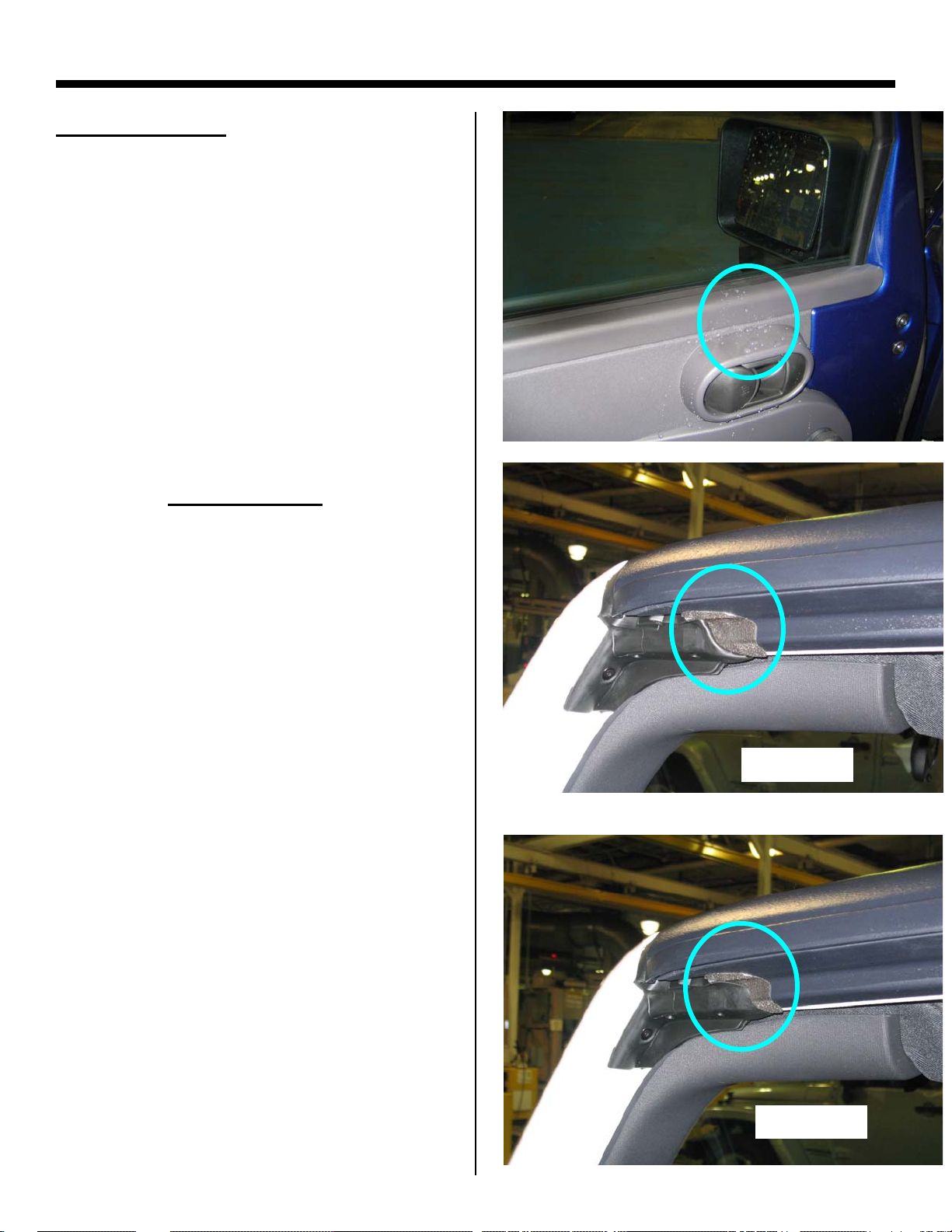
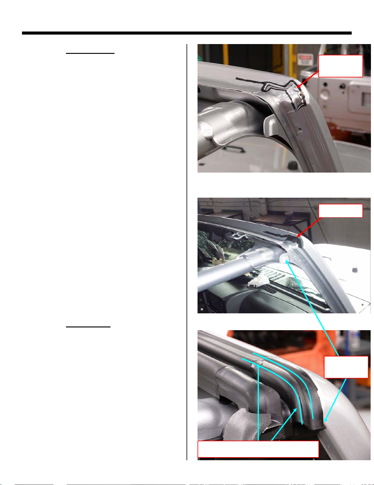
A-Pillar Foam/Mucket Repair Procedure
AREA OF LEAK:
• This repair procedure is applicable
when water is evident on the:
o Door Trim Panel
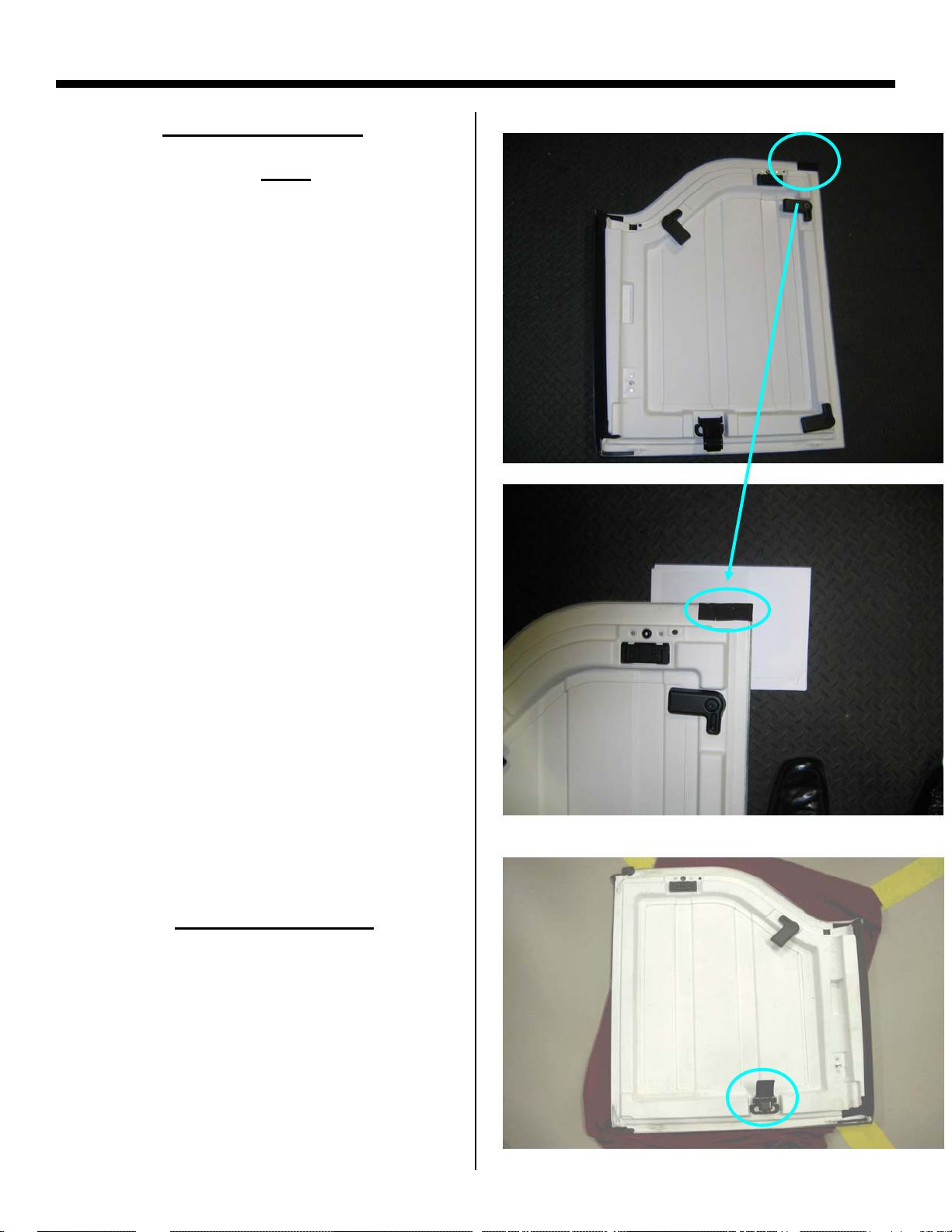
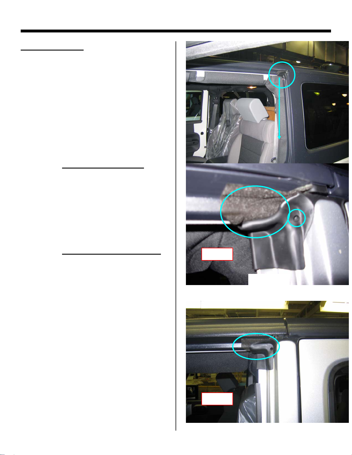
STEP 1: Header Mucket
• NOTE: This issue/repair applies to
both hard and soft top vehicles
• Inspect the header seal mucket for
the seal rolled under the freedom
panel or side rail. (Figure 8)
• If the seal is folded under, remove the
freedom panel or side rail and reinstall making sure not to distort the
mucket (Figure 9)
Labor Op. Code:
BAD
Figure 8
Figure 9
GOOD
4
Page 9
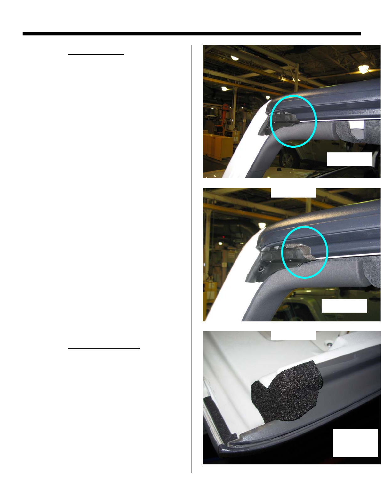
A-Pillar Foam/Mucket Repair Procedure
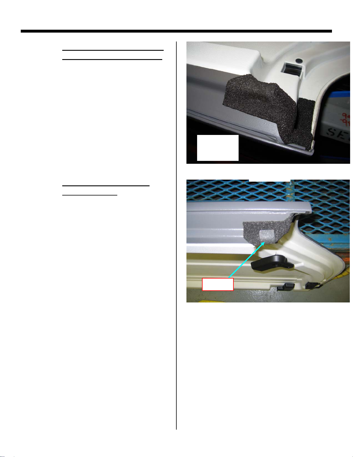
STEP 2: A-Pillar Foam
• NOTE: This issue/repair applies to
both hard and soft top vehicles
• Inspect the freedom panel or side rail
for damaged/missing foam
(Figure 10)
• If the foam is damaged or missing,
replace the foam using the foam kit
(68026937AB)
STEP 2: Foam Installation
• Install the foam to the freedom panel
as shown in Figure 12
• The foam installation is similar for
the soft top rail
BAD
Figure 10
GOOD
Figure 11
Labor Op. Code:
RH Panel
Shown
Figure 12
5
Page 10
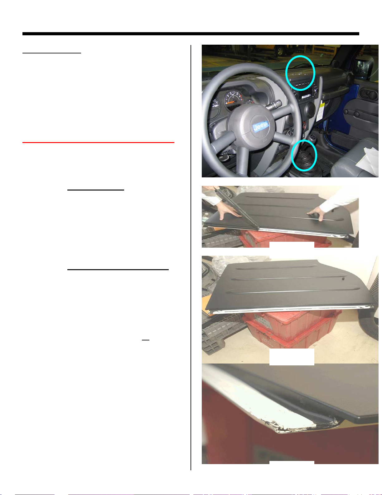
B-Pillar Mucket/Foam Seal Repair
AREA OF LEAK:
• This repair procedure is applicable
when water is evident on the:
o Instrument panel (Center)
or
o Console / Shifter
RIGHT HAND FREEDOM PANEL
STEP 1: Seal Removal
• Remove seal on Right panel
STEP 2: Tape and Butyl Removal
• Remove tape and butyl residue from
panel
• A rubber wheel bit can be used
• Clean Seal Surface with: 3M General
Purpose Adhesive Cleaner or
Products Acrysol, (if available) and
allow to dry completely
• Wipe seal surface with alcohol and
allow to dry completely.
Labor Op. Code:
Kent
Figure 13
Figure 14
Figure 15
6
Page 11
B-Pillar Mucket/Foam Seal Repair
R
R
STEP 3: Butyl Installation
• Place right hand freedom panel
upside down on a covered surface to
prevent scratching
• Apply 4 mm diameter Butyl, Pt #
68027813AA, to Rear Notch (Figure
17)
• Note: Follow groove between panels
and push butyl firmly in place
• Apply 4 mm diameter Butyl
68027813AA, to Front Notch
(Figure 18)
• Note: Follow groove between panels
and push butyl firmly in place
, Pt #
REA
FRONT
15mm
Figure 16
REA
20mm
15mm
Figure 17
FRONT
20mm
Labor Op. Code:
Figure 18
7
Page 12
B-Pillar Mucket/Foam Seal Repair
R
STEP 4: Seal Installation
• Keep freedom panel upside down for
the initial installation of the seal
• Remove tape liner from seal
NOTE: Secure the end molds first, then
finish with the middle of the seal
Rear Seal Mold
• Align REAR edge of NEW seal, Pt #
55397095AG to Right Freedom Panel
Notch.
• Compress butyl by installing seal in
direction of arrows (Figure 20)
• Note: No gap between installed seal
and outer edge of freedom panels.
(Figure 20)
Front Seal Mold
• Align FRONT edge of NEW seal, Pt #
55397095AG to Right Freedom Panel
Notch
• Compress butyl by installing seal in
direction of arrows (Figure 21)
• Note: No gap between installed seal
and outer edge of freedom panels.
(Figure 21)
REA
FRONT
Figure 19
Rear Mold
Figure 20
Labor Op. Code:
Figure 21
Front Mold
8
Page 13
B-Pillar Mucket/Foam Seal Repair
STEP 5: Pressurize Seal
• Flip panel back over to complete the
seal installation
• Locate seal cross car against the
middle rib in the freedom panel and
pressurize starting at the ends and
working toward the center
• A small roller or firm finger pressure
should be used to insure the seal
tape is adhered from front to rear,
THIS STEP IS CRITICAL
STEP 6: Install foam at Front
• Install GREY 30 X 75 mm Foam from
kit (68026937AB) along trim lines of
flame tip (Figure 24)
• NOTE: Make sure foam covers butyl
completely
This photo is for
reference only. Panel
was cut to show rib.
Locator rib in panel
Figure 22
Figure 23
Labor Op. Code:
Front of panel
Figure 24
9
Page 14
B-Pillar Mucket/Foam Seal Repair
STEP 7: Install foam at Rear
• Install BLACK 30 X 75 mm Foam from
kit (68026937AB) along trim lines of
flame tip (Figure 25)
• NOTE: Make sure foam covers butyl
completely
Figure 25
LEFT HAND FREEDOM PANEL
STEP 8: Install butyl at Rear
• Place Left hand freedom panel
upside down on a covered surface to
prevent scratching
• Add 4mm diameter butyl,
(68027813AA) to rear inboard corner
groove (Figure 27)
• Note: Push butyl firmly into groove
between panels until flush
REAR
Figure 26
70 mm
25 mm
Figure 27
Labor Op. Code:
10
Page 15
B-Pillar Mucket/Foam Seal Repair
STEP 9: Install foam at Rear
• Add 30 X 75 mm Black Foam from Kit
(68026937AB) to cover butyl
(Figure 28)
• NOTE: Make sure foam covers butyl
completely
STEP 10: Install front latches
• NOTE: This applies to both Right and
Left panels
• If the vehicle MDH is prior to 12/07/07,
replace the front latches with part
number 68004562AB (Figure 29)
Labor Op. Code:
Figure 28
Figure 29
11
Page 16
B-Pillar Mucket/Foam Seal Repair
AREA OF LEAK:
• This repair procedure is applicable
when water is evident on the:
o B-pillar roll bar
o B-pillar trim
o Freedom panel screw holes
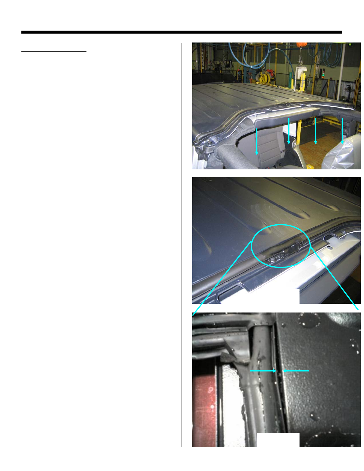
NOTE: Water that enters anywhere along
the hard top seal can travel over to the Bpillar and leak from the hard top
STEP 1: Inspect Hard Top Seal
• Inspect for any gaps between the
seal and hard top (Figure 30,31)
Figure 30
Labor Op. Code:
Figure 31
12
Page 17
B-Pillar Mucket/Foam Seal Repair
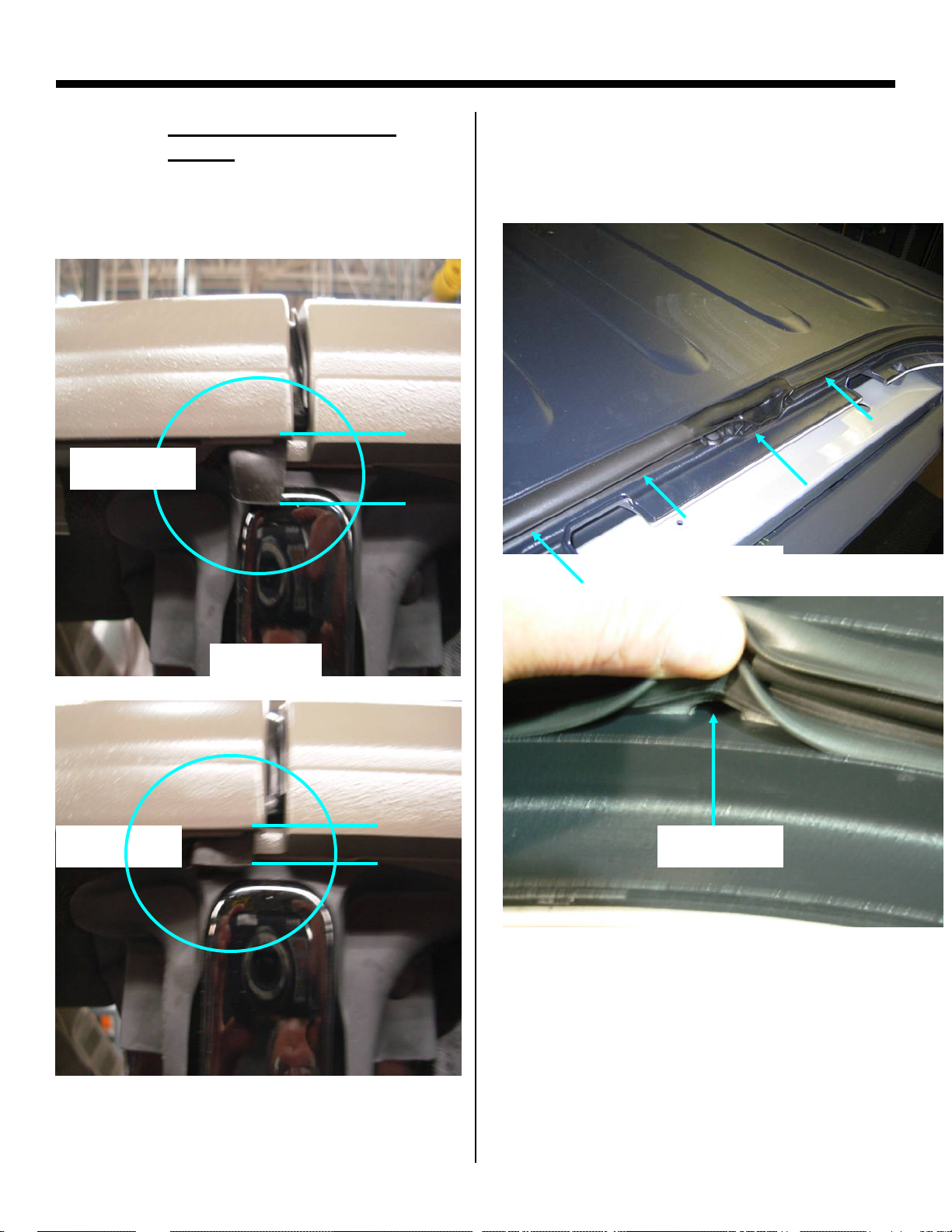
STEP 1: Inspect Hard Top Seal
(cont.)
Inspect the end molds for poor
•
installation (Figure 32)
BAD GAP
•
Inspect underneath the seal for any
skips with the tape/butyl along the
entire seal (Figure 34 & 35).
Figure 34
GOOD GAP
Figure 32
Figure 33
TAPE SKIP
Figure 35
Labor Op. Code:
13
Page 18
B-Pillar Mucket/Foam Seal Repair
STEP 2: Replace Hard Top Seal
If there are multiple skips or the leak
cannot be stopped, replace seal.
Remove all tape/butyl and clean with
alcohol prior to installation
A rubber wheel bit can be used to
remove the tape
Pre-apply butyl (68027813AA) on
hard top prior to installing the seal
(Figure 36)
It is critical that then end molds are
installed correctly and sufficient
pressure is applied to wet out the
butyl/tape (Figure 36)
Labor Op. Code:
Apply butyl
as shown
Pressurize
Figure 36
2mm
underflush
Figure 37
14
Page 19
B-Pillar Mucket/Foam Seal Repair
AREA OF LEAK:
• This repair procedure is applicable
when water is evident on the:
o B-plr trim or seat
NOTE: This repair applies to 4 door hard
top or soft top models
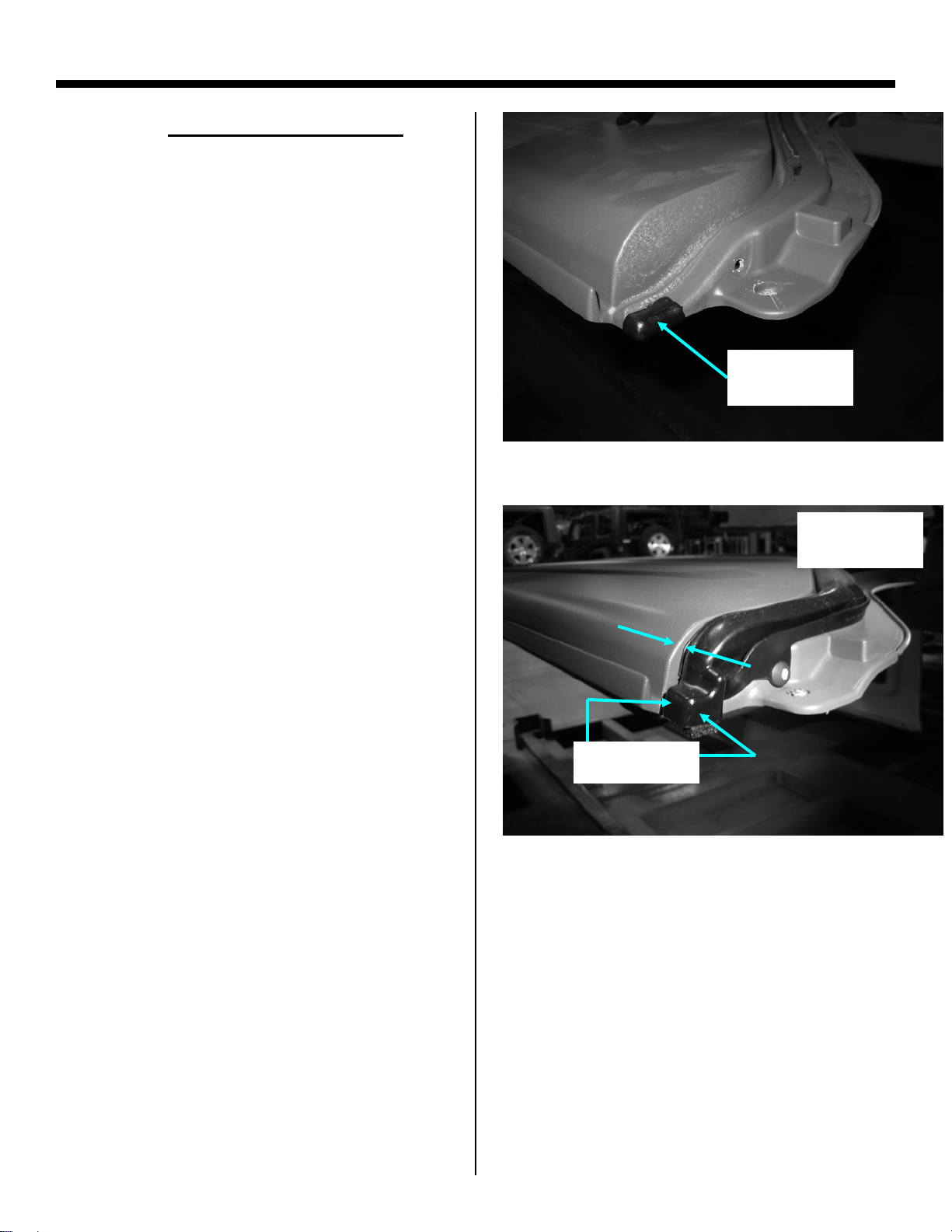
STEP 1: Inspect mucket detail
Inspect the mucket for a rolled under
condition (Figure 38)
Inspect the mucket for a missing
drain hole
STEP 2: Replace the mucket detail
If either of these conditions exist,
replace the mucket detail
(Part #:55395708/9AE)
Reinstall the panel or side rail making
sure not to distort the mucket
BAD
Figure 38
Labor Op. Code:
GOOD
Figure 39
15
Page 20
B-Pillar Mucket/Foam Seal Repair
STEP 3: Inspect Freedom Panel for
damaged or missing foam
• If the foam is damaged or missing,
replace the foam using the foam kit
(68026937AB)
STEP 4: Add additional foam to
freedom panel
Add a piece of foam to the freedom
panel as shown in Figure 41. This
foam can be created by cutting the 30
x 75mm GREY foam in half from the
foam kit (68026937AB)
Figure 41
NOTE: This foam is in addition to the foam
that is already on the panel
RH Panel
Shown
Figure 40
FOAM
Figure 41
Labor Op. Code:
16
Page 21
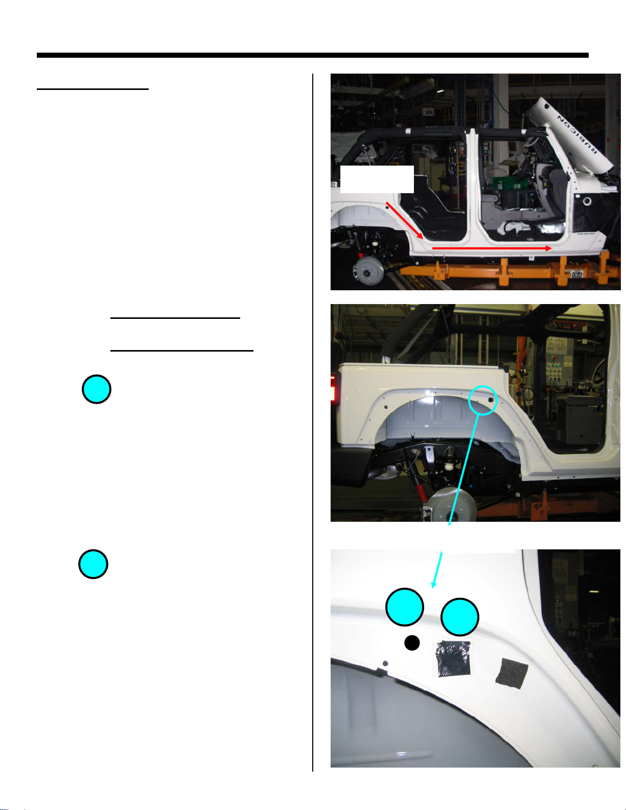
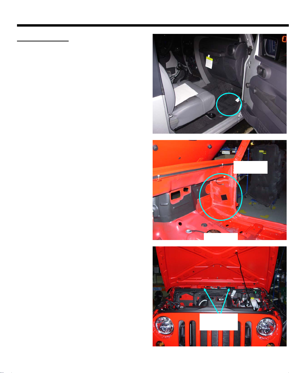
Rear Wheel Flare Hole Repair
AREA OF LEAK:
• This repair procedure is applicable
when water is evident on the:
o Front floor (wet carpet)
o Under seat
NOTE: This leak can be diagnosed by
applying a hose to the upper rear flare and
inspecting for water traveling along the
floor to the front
STEP 1: Remove Rear Flare
STEP 2: Replace/Install Patch
Hole :
1
NOTE: Vehicles built prior to 5/28/08 will
require this repair
• Inspect the body for missing or mis-
aligned tape over the hole as seen in
Figure 43
Add/Replace a tape patch over the
hole
Hole:
NOTE: Vehicles built prior to 5/01/09 will
require this repair
• Inspect the body for missing or mis-
Add/Replace a tape patch over the
Labor Op. Code:
2
aligned tape over the hole as seen in
Figure 43
hole
Leak Path
Figure 42
1
2
Figure 43
17
Page 22
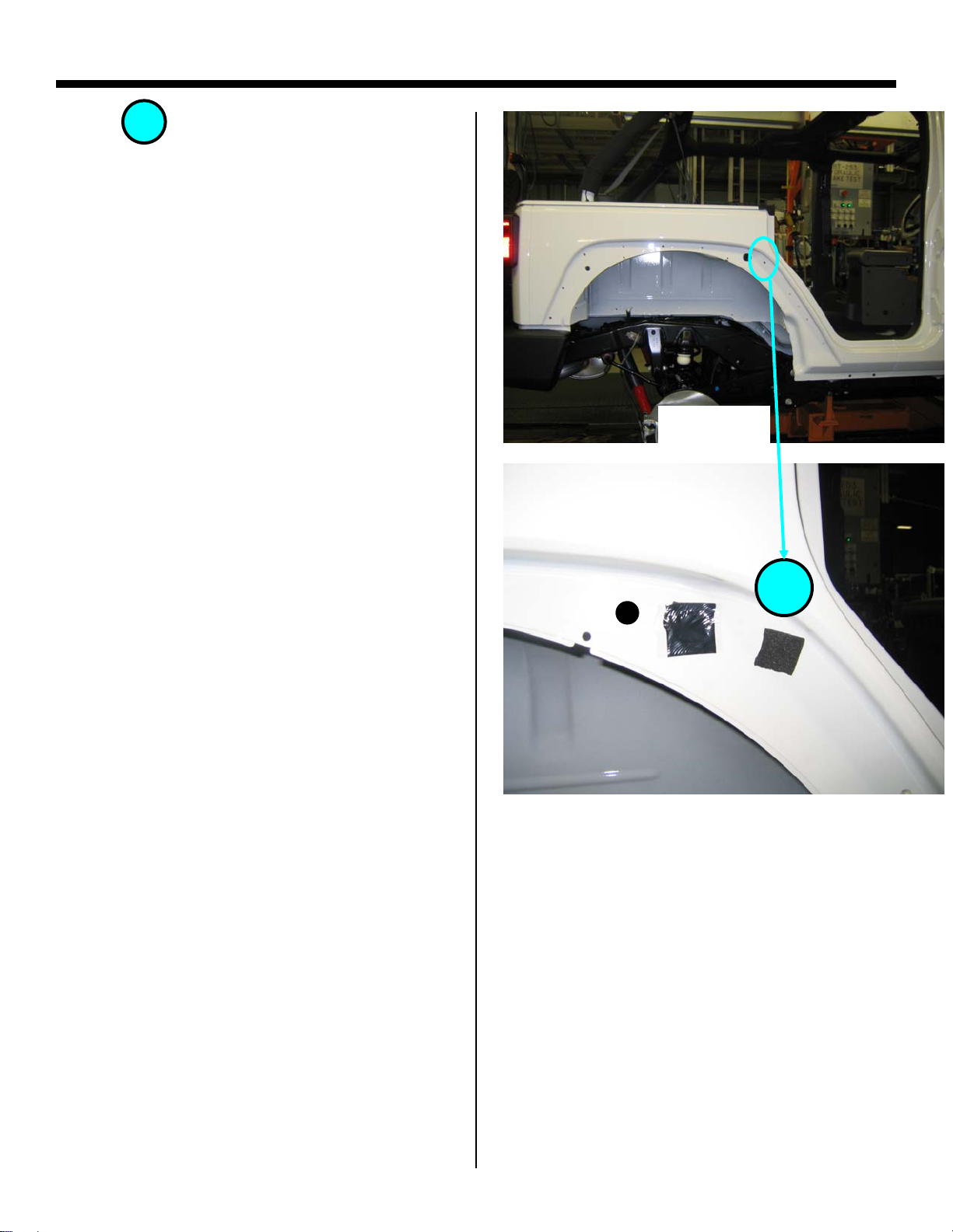
Rear Wheel Flare Hole Repair
Hole:
NOTE: Vehicles built prior to 7/22/08 will
require this repair
• Cut the BLACK 30 x 75 foam from the
Make sure the foam does not extend
Re-install flare
3
foam kit (68026937AB) in half and
apply over this hole (Figure 45)
past the flare trim line (appearance
issue)
Figure 44
3
Figure 45
Labor Op. Code:
18
Page 23
Cowl Side Panel Repair
AREA OF LEAK:
• This repair procedure is applicable
when water is evident on the:
o Front floor (wet carpet)
NOTE: These leaks can be diagnosed by
applying a hose in the cowl panel (Figure
47).
Leak area
Figure 46
Apply hose
in cowl area
Labor Op. Code: 235001
Figure 47
19
Page 24
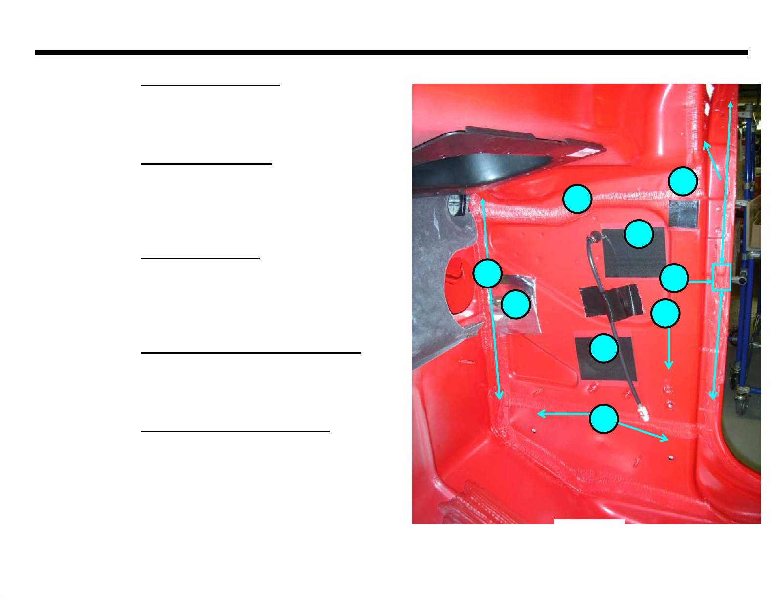
Cowl Side Panel Repair
Condition 1: Mastic patches/Plugs
Repair 1: Replace patch/plug
Condition 2: Check strap bracket
Repair 2: Remove bracket and apply a butyl
to holes
Condition 3: Seam sealer skips
Repair 3: Apply clear sealer
(part #: 04467708) to skip
Condition 4: Scuff trim foam damaged/missing
Repair 4: Replace trim clips
Condition 5: Antenna grommet not seated
Repair 5: Re-install grommet
Labor Op. Code: 235001
_-
1
5
1
3
1
Figure 48
1
4
3
2
20
Page 25
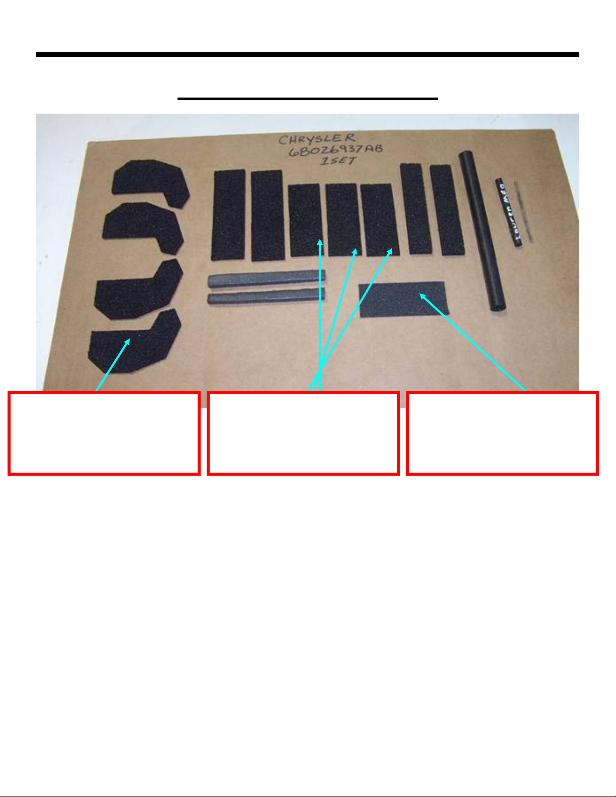
Appendix
Foam Kit: 68026937AB
A/B-Pillar Foam
Used on Pages (5,16,)
30 mm x 75mm BLACK Foam
Used on Pages (10,11)
30 mm x 75mm GREY Foam
Used on Pages (9,16)
Labor Op. Code:
21
Page 26

Appendix
Jeep Wrangler
Replacement Parts List
Part # Part Name Page(s)
68027813AA Butyl 2,7,10,14
04467708 Clear Sealer 20
68026937AB Foam Kit 5,9-11,16
55397454AE Windshield Header Seal 2
55395274/5AN Front Door Primary Seal 3
55395708/9AE B-Pillar Mucket 15
55397095AG Freedom Panel Seal 8
55397046AF Hard Top Seal 4DR 14
55397058AF Hard Top Seal 2DR 14
68004562AB Freedom Panel Latch 11
Labor Op. Code:
22
Page 27

JK Freedom Top
-Center Front-
Water Leak Repair
Reference TSB # 23-020-08 As Required for additional Repair Information
10/14/2008 1
Page 28
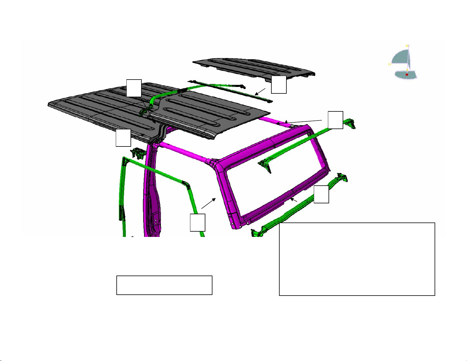
4
5
6
1
2
3
1.Windshield header seal
2.Windshield to cowl seal
3.Front door weatherseal
4.B pillar mucket
5.Hard top seal
Outside View
10/14/2008 2
6.Center freedom panel seal
Page 29
9
7
12
9
8
10
11
13
7. Left Freedom Panel
8. Panel to Panel Latches
9. Panel to Hard Top Latches
10. Hard Top
11. Right Freedom Panel
12. Latch & Base Assembly 68004562AB
Inside View
10/14/2008 3
13 Sport Bar Thumb Screws
Page 30

*Please note:
This package addresses water leaks that come from
inside the vehicle when the door is closed.
This package does not address
water that drips into the Vehicle
when the door is open.
This is a normal condition!
10/14/2008 4
Page 31

These parts with
Light Blue shaded
boxes are Optional /
Replace as required
2 Pair.
Foam Kit Contents
68026937AB
20 mm x 95 mm x 5 mm-
30 mm x 95 mm x 3 mmthick. 2 pieces.
thick. 2 pieces.
7mm OD x 71mm. 2 pieces
2 Pair
13mm OD x 8mm ID x 160mm. 1 piece.
9 mm x 100 mm x 6.35 mmthick. 2 pieces.
10/14/2008 5
30 mm x 75mm x 3 mmthick. 3 pieces. Black
Foam
30 mm x 75mm x 2 mmthick 1 piece. Gray Foam
These 4 pieces of foam are required
for the freedom panel repair.
Page 32

Additional Hard Top Foam Locations Included in
the foam kit. Replace as required.
3
1
4
4
3
1
2
3
4
2
2
1
10/14/2008 6
Page 33

Right Freedom Panel
Weather Strip Removal & Freedom panel Cleaning
10/14/2008 7
Page 34

Remove Right Freedom Panel Center Seal
10/14/2008 8
Page 35

Remove old Butyl & Tape from Right Freedom Panel
10/14/2008 9
Page 36

Note: Old Butyl Removed from Right Freedom Panel
Seal Surface
(White Strip)
Clean Seal Surface with: 3M General Purpose Adhesive Cleaner or Kent
Products Acrysol, (if available) and allow to dry completely. Rough up Seal
Surface with Medium Scotch Bright pad. Wipe Seal Surface with Alcohol and
allow to dry completely.
10/14/2008 10
Page 37

Note: Old Butyl Removed from Right Freedom Panel, Front &
Rear Notches
10/14/2008 11
Page 38

Place Right Freedom Panel
Upside down on a covered
work surface to prevent paint
Scratching.
Freedom Panel Notch Butyl installation
10/14/2008 12
Page 39

Page 15 Rear notch
Page 14 Front notch
10/14/2008 13
Page 40

Apply New 4 mm diameter Butyl, Pt # 68027813AA to Right
Freedom Panel, Front Notch. Note: Follow Groove between
panels and Push Butyl firmly in place.
Front Inboard
Butyl inside Grooves
20 mm
15 mm
10/14/2008 14
Page 41

Apply New 4 mm diameter Butyl, Pt # 68027813AA to Right
Freedom Panel, Rear Notch. Note: Follow Groove between
panels and Push Butyl firmly in place.
Front
Inboard
Butyl inside Grooves
15 mm
10/14/2008 15
20 mm
Page 42

Page 17 Rear Weather
Strip
Page 18 Front Weather
Strip
Freedom Panel Weather Strip installation
10/14/2008 16
Page 43

Align Rear edge of NEW Weather Strip, Pt # 55397095AG to
Right Freedom Panel Notch. Note: No gap between installed
Weather Strip and outer edge of freedom panels.
Compress butyl by installing
Weather Strip in direction of Arrows
Smooth out Butyl after
W/Strip installation
10/14/2008 17
Page 44

Align Front edge of NEW Weather Strip, Pt # 55397095AG to
Right Freedom Panel Notch. Note: No gap between installed
Weather Strip and outer edge of freedom panels.
Smooth out Butyl after
Weather Strip installation
Note: Remove Release tape and Press Weather Strip Firmly in
contact with Freedom Panel, Front AND Rear .
10/14/2008 18
Page 45

Note Both Ends of new W/Strip Located and installed to
Freedom Panel Center section still shown unattached
10/14/2008 19
Page 46

If Vehicle MDH is Before 12/17/07 Replace this Latch
on Right & Left Freedom Tops with 68004562AB.
Right Freedom Top Shown
Freedom Panel Latch and Base Assembly
Right and Left
10/14/2008 20
Page 47

Flip Right Freedom Panel
over to complete Weather
Strip installation.
10/14/2008 21
Page 48

Remove Release Tape, Locate W/Strip cross car against Rib in
the freedom panel and Pressurize to Freedom Panel starting at
the ends and working toward the center.
Cross Car Direction
Rib
10/14/2008 22
Page 49

A Small Roller or firm finger pressure should be used to
insure the Weather Strip tape is adhered from front to rear,
THIS STEP IS CRITICAL
10/14/2008 23
Page 50

Top View
Front, page 25 Rear, page 26
Flame Tips
Note: Make sure vertical rubber lip does not roll or get tucked under freedom
panel. Correct condition shown is Required at the Front AND
10/14/2008 24
Rear.
Page 51

Apply 3M 4298 adhesive promoter on the under side of the
flame tip and allow to dry. Align Gray 30 X 75 mm Foam
from kit along trim lines of Flame Tip.
Align Foam along these edges of Flame Tip
Front Flame Tip under side
10/14/2008 25
Page 52

Apply 3M 4298 adhesive promoter on the under side of the
flame tip and allow to dry. Align Black 30 X 75mm Foam
from kit along trim lines of Flame Tip.
Align Foam along these edges
of Flame Tip
Rear Flame Tip under side
10/14/2008 26
Page 53

Trim away excess Black Foam.
Rear Flame Tip - Top View
10/14/2008 27
Page 54

Left Freedom Panel
Place Left Freedom Panel Upside down on a covered work
surface to prevent paint Scratching
Clean Seal Surface with: 3M General Purpose Adhesive
Cleaner or Kent Products Acrysol, (if available) and allow to
dry completely. Rough up Seal Surface with Medium Scotch
Bright pad. Wipe Seal Surface with Alcohol and allow to dry
completely
Rear Inboard Corner Butyl & Foam installation
10/14/2008 28
Page 55

Add 4mm diameter Butyl, Pt # 68027813AA to Rear Inboard
Corner groove, Left Freedom Panel
Note: Push Butyl Firmly into groove
between panels until Flush
Outboard
100mm
100mm
Front
Front
10/14/2008 29
70mm
70mm
Page 56

Add 30 X 75 mm Black Foam from Kit to cover butyl
Front
10/14/2008 30
Page 57

Add 30 X 75 mm Black Foam from Kit to cover butyl.
Note Make sure Foam covers Butyl.
Outboard
10/14/2008 31
Page 58

Note: REMINDER Refer to Page 20 If Vehicle MDH is
Before 12/17/07
Freedom Top with 68004562AB.
. Replace Latch on Right & Left
Left Freedom Panel complete.
10/14/2008 32
Page 59

JK “A” Pillar- Header
Weather Strip
Water Leak Repair
Reference TSB # 23-025-08 As Required for additional Repair Information
10/14/2008 1
Page 60

*Please note:
This package addresses water leaks that come from
inside the vehicle when the door is closed.
This package does not address water
that drips into the Vehicle when the
door is open.
This is a normal condition!
10/14/2008 2
Page 61

5
4
6
1
2
1.Windshield header seal
3
2.Windshield to cowl seal
3.Front door weatherseal
4.B pillar mucket
Outside View
5.Hard top seal
6.Center freedom panel seal
10/14/2008 3
Page 62

Check door fit
• The door gap spec. is 5 +/-1.5 mm
Door Must be Flush to slightly under flush to A- Pillar
Adjust door Gap AND Flushness as described in
Body Section 23 of the Service Manual
10/14/2008 4
Page 63

Header Weather Strip
Remove Header Weather Strip from Body sheet metal and
clean up / remove all traces of old Tape and Butyl from
painted sheet metal surfaces before reinstallation of
butyl bead and new weather strip.
Clean Seal Surface with: 3M General Purpose Adhesive
Cleaner or Kent Products Acrysol, (if available) and allow to
dry completely.
Weather Strip Removal & Butyl Clean Up
10/14/2008 5
Page 64

Weather Strip Removal & Butyl Clean Up
All tape residue & butyl must be
removed across the entire
windshield frame!
Clean up / remove all traces of old Tape and Butyl from painted sheet
metal surfaces.
Alcohol wipe the clean sheet metal
and new weather strip.
10/14/2008 6
before installation of butyl bead
Page 65

Header Weather Strip
Butyl Placement and New Weather Strip Installation.
Right Side Shown on Pages 8, 9, & 10.
Left Side Not Shown but symmetrical / identical to Right
10/14/2008 7
Page 66

Fill in Gaps between Sheet Metal, Wrinkles, Holes
and Notches in this area with butyl until smooth.
3 mm x 3 mm butyl pad as
located ABOVE TAPE and
on mold line see page 11
Note: Vehicles built after 6/1/2008
MDH have this area filled in with
seam sealer from assembly plant.
Note:
60 mm
60 mm
Butyl bead MUST be
completely covered
by the header seal
mucket in this area.
Be careful DO NOT
allow squeeze out,
outside of installed
mucket!
20 mm
Inboard
10/14/2008 8
Right Side A-pillar
Page 67

Note: Green dots Show the area
where the header weather Strip
Adhesive Tape is to be located
4 mm diameter bead 68027813AA
Replacement Butyl Position. See
page 9 for Butyl Dimensions
Locate each end of the
Inboard
header weather strip
using this flange on
each side.
Right Side A-pillar
10/14/2008 9
Page 68

Locate and install NEW Weather Strip, Pt # Strip 55397454AB.
Remove Release tape and Pressurize Weather Strip Firmly in
contact with Header Sheet Metal to smooth out adhesive tape
and butyl, starting at the ends and working toward the center.
A small Roller or firm finger pressure should be used to insure
the Weather Strip tape is adhered completely from side to
side, THIS STEP IS CRITICAL
Gently pull weather strip rearward at mold line shown on page
9 and insert a 3 mm x 3 mm square piece of butyl .
10/14/2008 10
Page 69

Mold Line
3 mm x 3 mm butyl pad Shown
behind Weather Strip ABOVE
TWO SIDED TAPE and centered
over mold line
Inboard
Right Side A-pillar
10/14/2008 11
Header Seal Installed
Page 70

JK -B Pillar-
Water Leak Repair
9/4/2008 1
Page 71

*Please note:
This package addresses water leaks that come from
inside the vehicle when the door is closed.
This package does not address water
that drips into the Vehicle when the
door is open.
This is a normal condition!
9/4/2008 2
Page 72

5
4
6
1
2
1.Windshield header seal
3
2.Windshield to cowl seal
3.Front door weatherseal
4.B pillar mucket
Outside View
5.Hard top seal
6.Center freedom panel seal
9/4/2008 3
Page 73

Note Seal Shown with sealer skips allows water
behind seal. This requires the need for additional
Butyl to be placed to fill in these voids
Hard Top Seal at Center
W/Strip Repair -Try this step Prior to Replacement
9/4/2008 4
Page 74

Hard Top Seal at Center
Hard Top Seal at Center
Inspect the entire seal length side to side
Note Seal Shown gapping to roof
allows water behind seal. This
requires the seal to be replaced
to ensure it is firmly attached to the hard
top.
If tape is not firmly attached
replace the seal.
9/4/2008 5
Page 75

Hard Top Weather Strip
Remove Hard Top Weather Strip from Hard Top and clean
up / remove all traces of old Tape and Butyl from painted
surfaces before reinstallation of new weather strip.
Clean Seal Surface with: 3M General Purpose Adhesive
Cleaner or Kent Products Acrysol, (if available) and allow to
dry completely.
Weather Strip Removal & Butyl Clean Up
9/4/2008 6
Page 76

Hard Top Weather Strip
Alcohol wipe the clean painted surfaces, And Allow Alcohol
to dry completely before insallation of new weather strip.
Locate & install NEW Weather Strip, Pt # 55397058AI (2 DR)
or 55397046AF (4 DR). Place seal tight against roof / without
gaps as shown on page 5. Remove Release tape & Pressurize
Weather Strip Firmly in contact with Roof to smooth out
adhesive tape, Make sure adhesive tape is FIRMLY
PRESSURIZED against the roof panel while maintaining a zero
gap condition from side to side. A small Roller or firm finger
pressure should be used to insure the Weather Strip tape is
adhered completely side to side, THIS STEP IS CRITICAL
9/4/2008 7
Page 77

B- Pillar Weather Strip
Remove B - Pillar Mucket Weather Strip from body and
clean up / remove all traces of old Tape and Butyl from
painted surfaces before reinstallation of butyl bead and
new weather strip. Clean Seal Surface with: 3M General
Purpose Adhesive Cleaner or Kent Products Acrysol, (if
available) and allow to dry completely.
PAGE / S 9 & 11 Show the RIGHT SIDE B–PILLAR &
PAGE 12 SHOWS THE LEFT SIDE, THESE REWORKS
MUST BE DONE ON BOTH SIDES OF THE TRUCK
Mucket Removal, Clean Up, Butyl & Mucket
install and Mucket drain hole and Dam rework
9/4/2008 8
Page 78

Add a 4 mm diameter bead of Butyl 68027813AA
Add a 4 mm diameter bead of Butyl 68027813AA
as shown to fill in sheet metal gaps.
as shown to fill in sheet metal gaps.
Top of Right B – Pillar With Mucket Seal removed
Top of Right B – Pillar With Mucket Seal removed
9/4/2008 9
Page 79

B- Pillar Weather Strip
Vehicles built After July 1, 2008 will have the drain hole
& foam already installed.
The steps on the next page show how to add the drain
hole & foam dam.
If B-Pillar weather strip needs to be replaced order the
following part numbers:
55395708AC – RT Side
55395709AC – LT Side
9/4/2008 10
Page 80

Note Single hole paper punch used to add Drain Hole
Hole Shown
located at the
rearward /
lowest position
possible
9/4/2008 11
Front
Right B – Pillar ALL VIEWS
Page 81

Foam Tape must be adhered to the front portion
of the drain cup as shown to act as a dam
Left B – Pillar TOP VIEW
9/4/2008 12
Page 82

JK –Half Doors-
Water Leak Repair
9/4/2008 1
Page 83

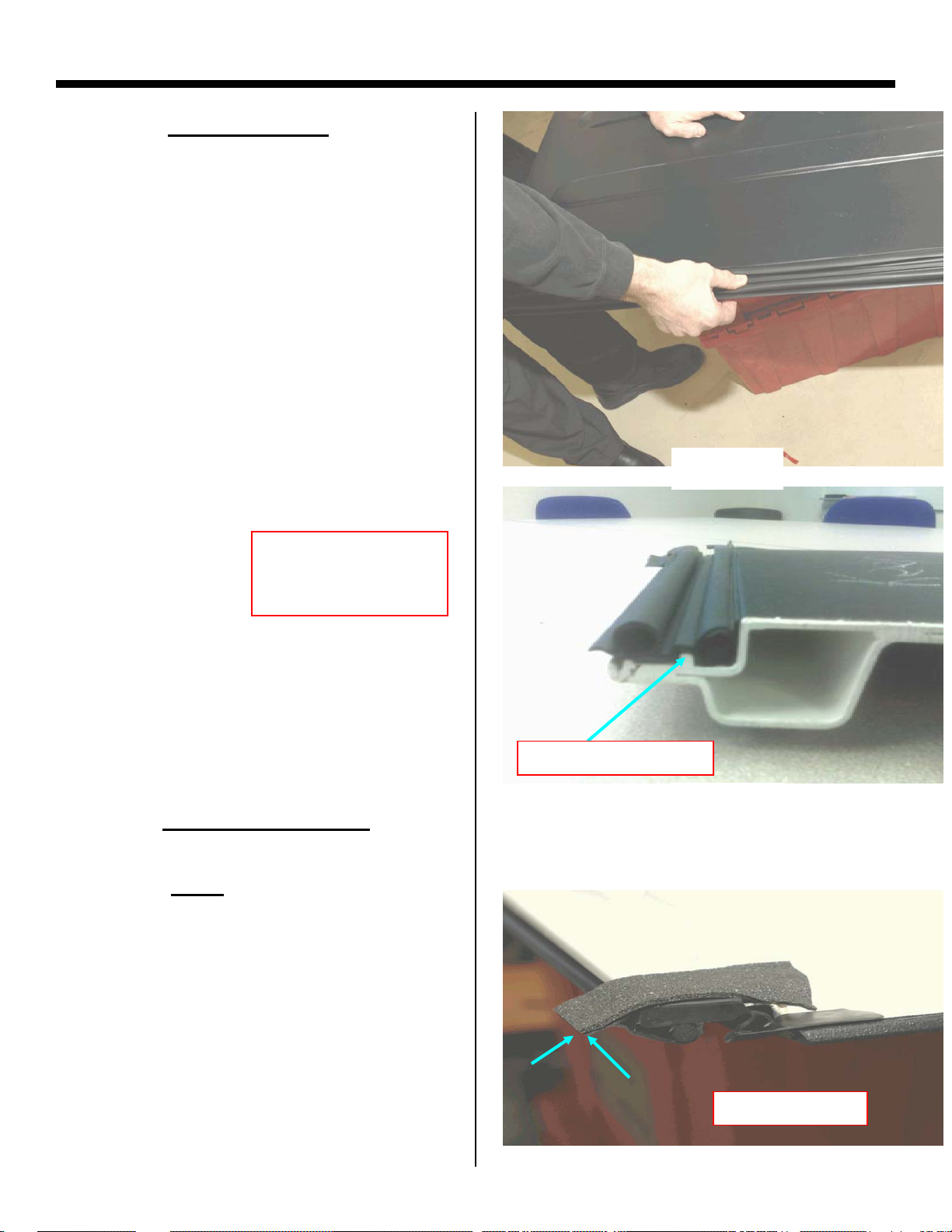
Measuring of Door Posts For Proper Preload
1. Lay Door on Flat Clean Surface.
2. Measure Posts.
3. Use Heat Gun to Heat up Posts as shown
on page 3.
4. Slide Pipe over Posts and Bend to Correct
Dimension as shown on
page 3.
Set this dimension as shown to the upper edge
of each peg to the dimensions shown on page 3
9/4/2008 2
Page 84

Heat Post: Caution too much heat will melt
Door, Maintain 12 inches for 2 Min. Max
Once heated Slide Pipe Over Post and Bend Post to
Correct Dimension
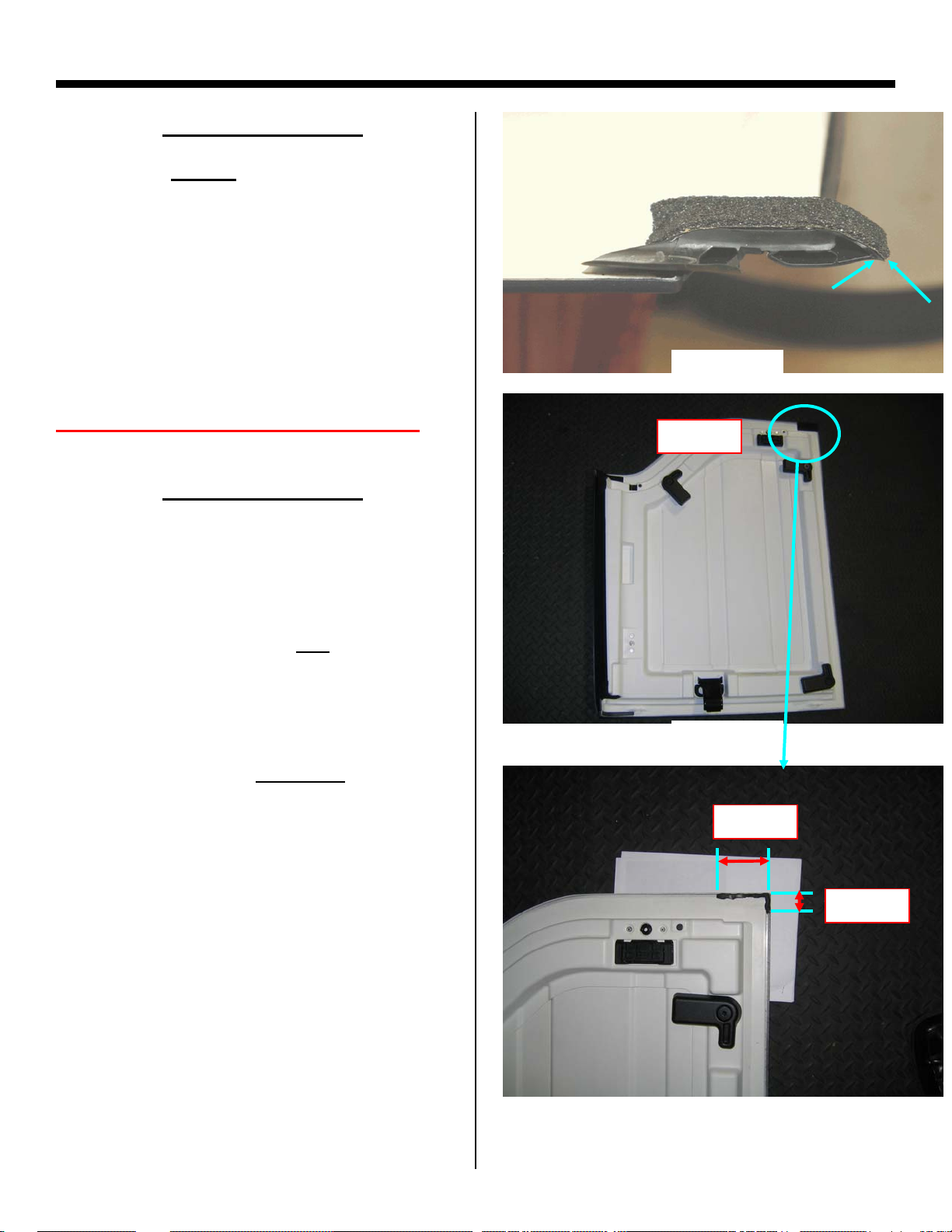
Front Door Post Dimensions (R & L)
Front Post 46.0mm
Rear Post 37.0mm
Rear Door Post Dimensions (R & L)
Front Post 30.0mm
Rear Post 40.0mm
9/4/2008 3
Note: Dimensions are from flat surface to the top of post.
Page 85

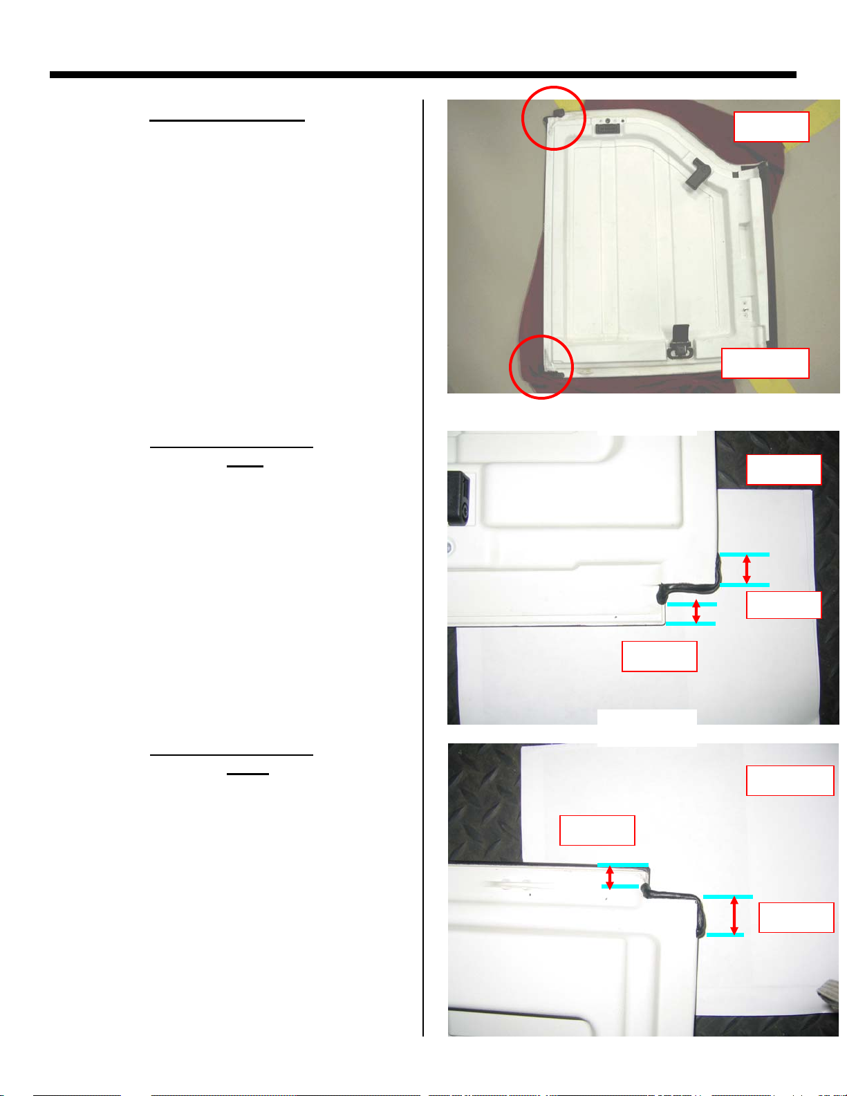
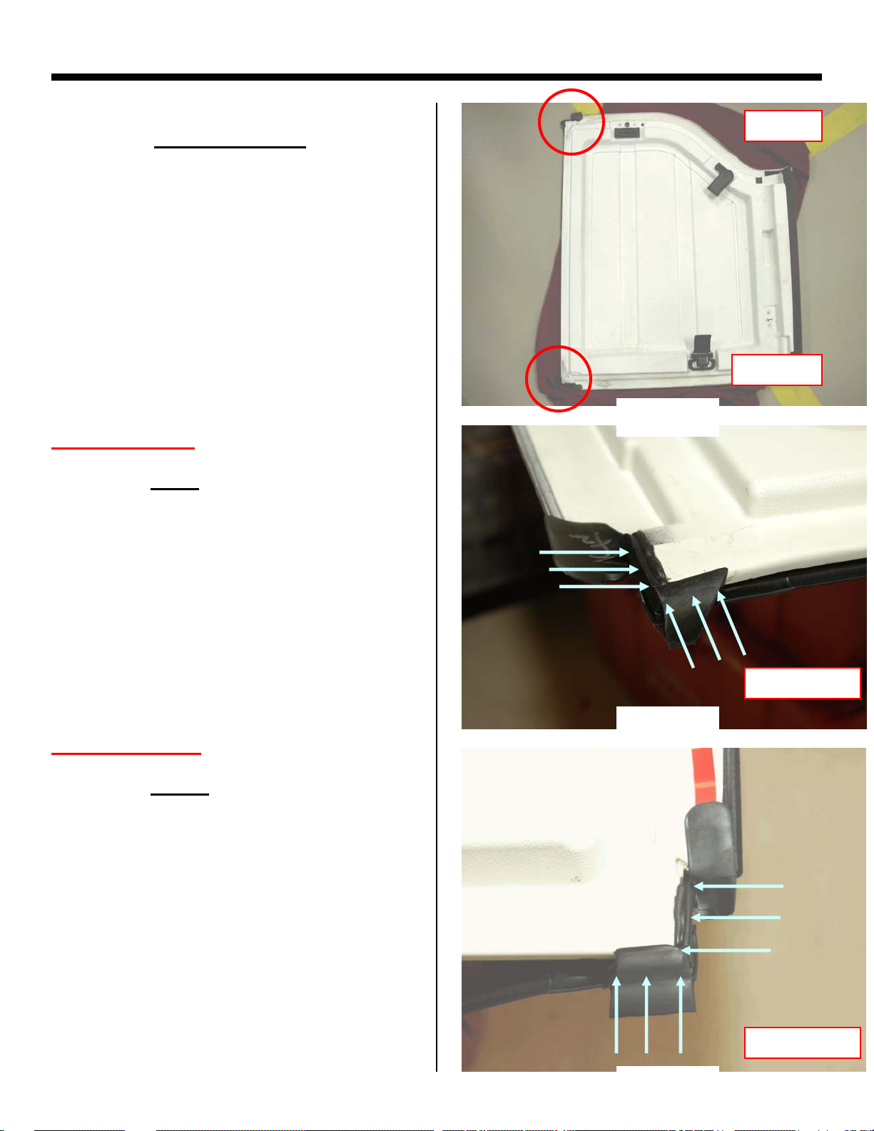
Add 4 mm diameter bead 68027813AA Butyl
Between Door Seal and door as shown on Page 5.
Front Door Upper “A” Pillar Corner
9/4/2008 4
Page 86

Add 4mm Diameter Butyl bead 6 inches
forward, and 6 inches rearward as shown
in RED
s
e
h
c
n
I
6
s
e
ch
n
I
6
Door “A” Pillar Corner
Close up view of area circled on page 4
Front of Door
9/4/2008 5
Page 87

Make Sure Seals Are Installed Correctly
Seal is not seated in channel
Correct
9/4/2008 6
Page 88

MUCKET
68003655AB KIT DOOR RAIL SEAL
4DR JK
B-PILLAR FOAM
B-PILLAR MUCKET FOAM
A-PILLAR FOAM
A-PILLAR FRONT
FOAM
C-PILLAR FOAM
9/4/2008 7
Page 89

MUCKET
68003645AB KIT DOOR RAIL SEAL
2DR JK
A-PILLAR FOAM
A-PILLAR FRONT
FOAM
B-PILLAR FOAM
9/4/2008 8
Page 90

JK – Soft Top Water
Leak Repair Tips
10/14/2008 1
Page 91

Header Seal Cup Folded under
10/14/2008 2
Correct
Page 92

Proper Quarter Window Installation
Incorrect – Retainer Not Rolled into Door Rail
Correct
10/14/2008 3
Page 93

Half Door, Side Curtain, or Rear Window Zipper Leaks
Can Be repaired by using Beeswax or Snow Seal as a
sealant.
10/14/2008 4
Water Seeping Through Zipper
Tape or Zipper Teeth
Page 94

MUCKET
68003655AB KIT DOOR RAIL SEAL
4DR JK
B-PILLAR FOAM
B-PILLAR MUCKET FOAM
A-PILLAR FOAM
A-PILLAR FRONT
FOAM
C-PILLAR FOAM
10/14/2008 5
Page 95

MUCKET
68003645AB KIT DOOR RAIL SEAL
2DR JK
A-PILLAR FOAM
A-PILLAR FRONT
FOAM
B-PILLAR FOAM
10/14/2008 6
Page 96

JK Water Leak Foam Repair Kit – Supplemental Information
P/N 68026937AA
23-041-07 Soft Top – Water Leak at Upper A-Pillar, Door Seal to Door Rail Interface
23-001-07 Modular Hard Top Freedom Panel Water Leaks
Foam Kit includes the following foam pieces:
Foam to be installed
on right Freedom
Panel as per Fig. 6.
Both pieces to be
installed on Freedom
Panels as per Fig. 4,
one on the left panel
and one on the right
Both pieces to be
installed on Freedom
Panels as per Fig. 5,
one on the left panel
and one on the right
Foam to be installed
on Freedom Panels as
per Fig. 7, one on the
left panel and one on
the right
Foam to be installed
on Windshield Header
Seal as per Fig. 3
All four pieces (two
right and two left) to
be installed on
Freedom Panels as per
Fig. 4, one left and
one right to be
installed on door rails
as per Fig. 1 & 2
Foam to be installed
on right Freedom
Panel as per Fig. 8.
Page 1 of 5
Page 97

Figure 1 – Rough Position of Foam on Right
Door Rail. Reference location 1 on both left
and right sides of vehicle.
(1) – Door frame rail foam
(2) – New black foam (Red highlighted
foam). One piece left handed and one piece
right handed. Loose fit to door frame rail.
(3) – Plastic door frame rail - Leading
end/edge removed from vehicle to affect
repair.
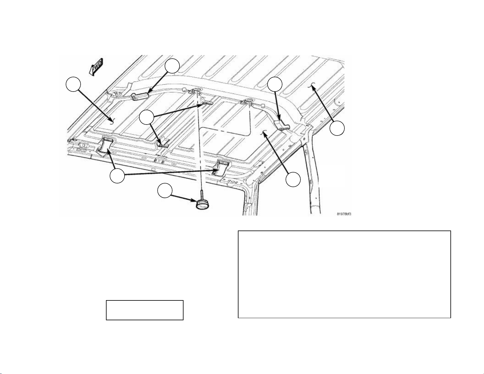
Reference – Foam Locations on Vehicle (Soft Tops)
1
Figure 2 – Black Foam Fully Seated
– Ensure that header seal is not
Note
pinched under foam when re-installing
the door rail.
Page 2 of 5
Page 98

C
Left Side
View
Right Side
View
A1
B2
Reference – Foam Locations on Vehicle (Hard Tops)
B1
Top View
A1
B1
A2
Front of Vehicle
A2
B2
D
Rear of Vehicle
Page 3 of 5
Page 99

(3)
(2)
Figure 3 – Windshield Header Seal Molded
Detail (Upper A-Pillar shown without tops)
Reference Locations A1 & A2
(1)
1 - Dark Gray Foam at End of Header Seal - Left Side of
Windshield Frame shown.
2 - Windshield Header Seal
3 - Windshield Frame - Upper A-Pillar - Left Side
(3)
(1)
(1)
(2)
(1)
(2)
Figure 4 – Rear of left Freedom Panel shown. Figure 5 – Front of left Freedom Panel Figure 6 – Rear of right Freedom Panel shown.
Reference locations B1 & B2. shown. Reference locations A1 & A2. Reference location D.
(1) – Blue highlighted foam (1) - Orange highlighted foam (1) – Dark green highlighted foam
(2) – 2-way freedom panel locator (2) - Red highlighted foam
(3) - Red highlighted foam
Page 4 of 5
Page 100

N
(1)
(1)
ew Seal
Figure 7 – Front of left Freedom Panel showing Figure 8 – Front of right freedom panel showing
one additional foam, required only on vehicles one additional foam, required on vehicles built
built prior to 3/01/07. Reference locations A1 prior to 3/27/07, unless a new seal was installed
& A2. as shown by photos on side. Reference location C.
(1) – Turquoise highlighted foam (1) – Purple highlighted foam
Old Seal
Page 5 of 5
 Loading...