

Page 1

2018 JEEP® WRANGLER JK USER GUIDE
Page 2
Important
Get warranty and other information online – you can
review and print or download a copy of the Owner’s Manual,
Navigation/Uconnect manuals and the limited warranties
provided by FCA US LLC for your vehicle by visiting
www.mopar.com (U.S.) or www.owners.mopar.ca (Canada).
Click on the applicable link in the “Popular Topics” area of the
www.mopar.com (U.S.) or www.owners.mopar.ca (Canada)
homepage and follow the instructions to select the applicable
year, make and model of your vehicle.
The driver’s primary responsibility is the safe operation of the
vehicle. Driving while distracted can result in loss of vehicle control,
resulting in a collision and personal injury. FCA US LLC strongly
recommends that the driver use extreme caution when using any
device or feature that may take their attention o the road.
Use of any electrical devices, such as cellular telephones, computers,
portable radios, vehicle navigation or other devices, by the driver
while the vehicle is moving is dangerous and could lead to a serious
collision. Texting while driving is also dangerous and should never be
done while the vehicle is moving.
If you find yourself unable to devote your full attention to vehicle
operation, pull o the road to a safe location and stop your vehicle.
Some states or provinces prohibit the use of cellular telephones or
texting while driving. It is always the driver’s responsibility to comply
with all local laws.
Page 3

Congratulations on selecting your new FCA
US LLC vehicle. Be assured that it represents
precision workmanship, distinctive styling,
and high quality.
ALWAYS drive safely and pay attention to the
road. ALWAYS drive safely with your hands on
the steering wheel. You have full responsibility and assume all risks related to the use of
the features and applications in this vehicle.
Only use the features and applications when
it is safe to do so. Failure to do so may result
in an accident involving serious injury or
death.
This guide illustrates and describes the operation of features and equipment that are
either standard or optional on this vehicle.
This guide may also include a description of
features and equipment that are no longer
available or were not ordered on this vehicle.
Please disregard any features and equipment
described in this guide that are not available
on this vehicle. FCA US LLC reserves the
right to make changes in design and specifications and/or make additions to or improve-
ments to its products without imposing any
obligation upon itself to install them on products previously manufactured.
This User Guide has been prepared to help
you quickly become acquainted with the important features of your vehicle. It contains
most things you will need to operate and
maintain the vehicle, including emergency
information.
When it comes to service, remember that your
authorized dealer knows your Jeep
best, has factory-trained technicians and
genuine MOPAR
satisfaction.
®
parts, and cares about your
®
vehicle
HOW TO FIND YOUR OWNER’S MANUAL ONLINE
This publication has been prepared as a reference item to help you quickly become acquainted with the most important features
and processes of your vehicle. It contains
most things you will need to operate and
maintain the vehicle, including emergency
information and procedures.
This User Guide is not a replacement for the full
Owner’s Manual, and does not fully cover every
operation and procedure possible with your vehicle.
For more detailed descriptions of the topics
discussed in this User Guide, as well as
information covering features and processes
not covered in this User Guide, the full vehicle Owner’s Manual can be accessed for
free online in a printer-friendly PDF format.
To get the full Owner’s Manual or applicable
supplement for your vehicle, follow the appropriate web address below:
www.mopar.com/en-us/care/owners-manual.html
(U.S. Residents)
www.owners.mopar.ca (Canadian Residents)
FCA US LLC is committed to protecting our
environment and natural resources. By converting from paper to electronic delivery for
the majority of the user information for your
vehicle, together we greatly reduce the demand for tree-based products and lessen the
stress on our environment.
WELCOME FROM FCA US LLC
1
Page 4

HOW TO USE THIS MANUAL
Essential Information
Each time direction instructions (left/right or
forwards/backwards) about the vehicle are
given, these must be intended as regarding
an occupant in the driver's seat. Special
cases not complying with this rule will be
properly specified in the text.
The figures in this User Guide are provided by
way of example only: this might imply that
some details of the image do not correspond
to the actual arrangement of your vehicle.
HOW TO USE THIS MANUAL
In addition, the User Guide has been conceived considering vehicles with steering
wheel on the left side; it is therefore possible
that on vehicles with steering wheel on the
right side, the position or construction of
some controls is not exactly mirror-like with
respect to the figure.
To identify the chapter with the information
needed you can consult the index at the end
of this User Guide.
Chapters can be rapidly identified with dedicated graphic tabs, at the side of each odd
page. A few pages further there is a key for
getting to know the chapter order and the
relevant symbols in the tabs. There is always
a textual indication of the current chapter at
the side of each even page.
Symbols
Some vehicle components have colored labels whose symbols indicate precautions to
be observed when using this component.
ROLLOVER WARNING
Utility vehicles have a significantly higher
rollover rate than other types of vehicles. This
vehicle has a higher ground clearance and a
higher center of gravity than many passenger
vehicles. It is capable of performing better in
a wide variety of off-road applications. Driven
in an unsafe manner, all vehicles can go out
of control. Because of the higher center of
gravity, if this vehicle is out of control it may
roll over while some other vehicles may not.
Do not attempt sharp turns, abrupt maneuvers, or other unsafe driving actions that can
cause loss of vehicle control. Failure to operate this vehicle safely may result in a collision, rollover of the vehicle, and severe or
fatal injury. Drive carefully.
Rollover Warning Label
Failure to use the driver and passenger seat
belts provided is a major cause of severe or
fatal injury. In fact, the U.S. government
notes that the universal use of existing seat
belts could cut the highway death toll by
10,000 or more each year and could reduce
disabling injuries by two million annually. In
a rollover crash, an unbelted person is significantly more likely to die than a person wearing a seat belt. Always buckle up.
2
Page 5

WARNINGS AND CAUTIONS
While reading this User Guide you will find a
series of WARNINGS to be followed to prevent incorrect use of components which
could cause accidents or injuries.
There are also CAUTIONS that must be followed to prevent against procedures that
could result in damage to your vehicle.
HOW TO USE THIS MANUAL
3
Page 6

4
Page 7

GRAPHICAL TABLE OF CONTENTS
GETTING TO KNOW YOUR VEHICLE
GETTING TO KNOW YOUR INSTRUMENT PANEL
SAFETY
STARTING AND OPERATING
IN CASE OF EMERGENCY
SERVICING AND MAINTENANCE
TECHNICAL SPECIFICATIONS
MULTIMEDIA
CUSTOMER ASSISTANCE
INDEX
Page 8

6
Page 9

GRAPHICAL TABLE OF CONTENTS
GRAPHICALTABLE OF CONTENTS
INSTRUMENT PANEL...........8
INTERIOR...................9
7
Page 10
INSTRUMENT PANEL
GRAPHICAL TABLE OF CONTENTS
Instrument Panel
1 — Air Outlet 7 — Climate Controls
2 — Instrument Cluster 8 — Power Outlet
3 — Radio 9 — Lower Switch Bank
4 — Assist Handle 10 — Power Mirror Switch — If Equipped
5 — Glove Compartment 11 — Horn
6 — Power Window Switches
8
Page 11
INTERIOR
Interior Features
1 — Seats 5 — Switch Panel
2 — Power Window Switches 6 — Transmission Gear Selector
3 — Radio 7 — Four-Wheel Drive Gear Selector
4 — Climate Controls
9
Page 12

10
Page 13

GETTING TO KNOW YOUR VEHICLE
GETTINGTO KNOW YOUR VEHICLE
KEYFOB...................13
KeyFob.....................13
IGNITIONSWITCH............14
Ignition Key Removal ............14
REMOTE STARTING SYSTEM —
IFEQUIPPED................15
How To Use Remote Start ..........15
Remote Start Abort Message ........15
To Enter Remote Start ............15
To Exit Remote Start Mode Without
Driving The Vehicle ..............16
To Exit Remote Start Mode And Drive
The Vehicle...................16
General Information .............16
SENTRYKEY................17
Replacement Key Fobs ...........17
Customer Key Programming ........18
General Information .............18
VEHICLE SECURITY ALARM —
IFEQUIPPED................19
Rearming The System ............19
To Arm The System .............19
To Disarm The System ............19
DOORS ...................20
Upper Half Door Window Removal —
If Equipped ..................20
Front Door Removal..............20
Rear Door Removal (Four-Door Models) . .21
SEATS ....................23
Heated Seats — If Equipped ........23
60/40 Split Folding Rear Seat —
Four Door Models ..............24
Front Passenger Easy Entry Seat —
Two Door Models ...............25
Tip ‘n Slide Seats —
Two Door Models ...............25
Removing The Rear Seat —
Two Door Models ...............26
HEADRESTRAINTS...........27
Front Head Restraints ............27
Rear Head Restraints —
Two Door Model ................28
Rear Head Restraints —
Four Door Model ...............28
STEERINGWHEEL............29
Tilt Steering Column .............29
MIRRORS ..................29
Heated Mirrors — If Equipped .......29
EXTERIORLIGHTS ...........29
Headlights And Parking Lights .......29
Daytime Running Lights — If Equipped .30
High/Low Beam Switch ...........30
Flash-To-Pass .................30
Automatic Headlights — If Equipped . .30
Front Fog Lights ...............30
Turn Signals ..................30
Lane Change Assist — If Equipped ....31
Lights-On Reminder .............31
11
Page 14

WINDSHIELD WIPERS AND
WASHERS..................31
Windshield Wiper Operation.........31
Rear Window Wiper/Washer —
If Equipped ..................32
CLIMATECONTROLS..........33
Automatic Climate Control Overview....33
Automatic Temperature Control (ATC) —
If Equipped ..................37
Operating Tips .................37
GETTING TO KNOW YOUR VEHICLE
POWER WINDOWS —
IFEQUIPPED ...............38
Wind Buffeting ................39
REMOVABLE TOP
INFORMATION ..............39
Sunrider And Soft Top ............39
Hard Top And Freedom Top .........47
Dual Top — If Equipped ...........50
Wind Buffeting ................51
HOOD .....................51
Opening The Hood ..............51
Closing The Hood ...............51
REARSWINGGATE...........51
INTERNAL EQUIPMENT ........52
Power Outlets .................52
Power Inverter — If Equipped .......55
12
Page 15
KEY FOB
Your vehicle uses a key start ignition system.
The ignition system consists of a Remote
Keyless Entry (RKE) key fob with an ignition
switch.
Key Fob
The key fob allows you to lock or unlock the
doors and liftgate from distances up to approximately 66 ft (20 m) using a handheld
key fob. The key fob does not need to be
pointed at the vehicle to activate the system.
NOTE:
In the ON/RUN position, the lock button is
disabled. Only the unlock button is enabled.
Key Fob
1 — Unlock
2 — Remote Start — If Equipped
3 — Lock
To Unlock The Doors And Swing Gate
Push and release the key fob unlock button
once to unlock the driver's door only, or twice
to unlock all the doors and swing gate. When
the key fob unlock button is pushed, the
Illuminated Entry will initiate, and the turn
signal lights will flash twice.
To Lock The Doors And Swing Gate
Push and release the lock button on the key
fob to lock all doors. The turn signals will
flash, and the horn will chirp once to acknowledge the lock signal.
General Information
The following regulatory statement applies to
all Radio Frequency (RF) devices equipped in
this vehicle:
This device complies with Part 15 of the FCC
Rules and with Industry Canada licenseexempt RSS standard(s). Operation is subject to the following two conditions:
1. This device may not cause harmful
interference.
13
Page 16
2. This device must accept any interference
received, including interference that may
cause undesired operation.
NOTE:
Changes or modifications not expressly approved by the party responsible for compliance could void the user’s authority to operate the equipment.
IGNITION SWITCH
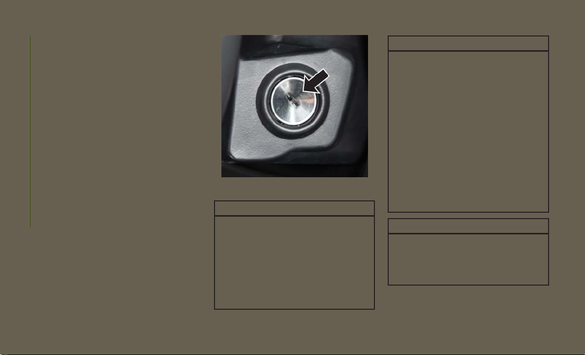
Ignition Key Removal
1. Place the gear selector in PARK (if
equipped with an automatic
transmission).
2. Turn the ignition switch to the ACC (Accessory) position.
GETTING TO KNOW YOUR VEHICLE
3. Push the key and cylinder inward and
rotate the key to the LOCK position.
4. Remove the key from the ignition switch
lock cylinder.
Ignition Switch
WARNING!
• Before exiting a vehicle, always shift the
automatic transmission into PARK or the
manual transmission into FIRST gear or
REVERSE, apply the parking brake, then
turn the engine OFF, remove the key fob
from the vehicle and lock your vehicle.
• Never leave children alone in a vehicle,
or with access to an unlocked vehicle.
WARNING!
• Allowing children to be in a vehicle unattended is dangerous for a number of
reasons. A child or others could be seriously or fatally injured. Children should
be warned not to touch the parking
brake, brake pedal or the gear selector.
• Do not leave the key fob in or near the
vehicle, or in a location accessible to
children. A child could operate power
windows, other controls, or move the
vehicle.
• Do not leave children or animals inside
parked vehicles in hot weather. Interior
heat build-up may cause serious injury
or death.
CAUTION!
An unlocked vehicle is an invitation for
thieves. Always remove key fob from the
vehicle and lock all doors when leaving the
vehicle unattended.
14
Page 17

REMOTE STARTING SYSTEM — IF EQUIPPED
This system uses the key fob to start the
engine conveniently from outside the vehicle
while still maintaining security. The system
has a range of approximately 300 ft (91 m).
NOTE:
• The vehicle must be equipped with an automatic transmission to be equipped with
Remote Start.
• Obstructions between the vehicle and key
fob may reduce this range.
How To Use Remote Start
All of the following conditions must be met
before the engine will remote start:
• Gear selector in PARK
• Doors closed
• Hood closed
• Hazard switch off
• Brake switch inactive
(brake pedal not pushed)
• Ignition key removed from ignition
• Battery at an acceptable charge level
• PANIC button not pushed
• System not disabled from previous remote
start event
• Vehicle security alarm not active
WARNING!
• Do not start or run an engine in a closed
garage or confined area. Exhaust gas
contains Carbon Monoxide (CO) which is
odorless and colorless. Carbon Monoxide is poisonous and can cause serious
injury or death when inhaled.
• Keep key fobs away from children. Operation of the Remote Start System, windows, door locks or other controls could
cause serious injury or death.
Remote Start Abort Message
The following messages will display in the
instrument cluster display if the vehicle fails
to remote start or exits remote start prematurely:
• Remote Start Aborted — Door Open
• Remote Start Aborted — Hood Open
• Remote Start Aborted — Fuel Low
• Remote Start Aborted — Swing Gate Open
• Remote Start Aborted — System Fault
The instrument cluster display message stays
active until the ignition is turned to the ON/
RUN position.
To Enter Remote Start
Push and release the remote start button on
the key fob twice within five seconds. The
vehicle doors will lock, the parking lights will
flash and the horn will chirp twice (if programmed). Then, the engine will start and the
vehicle will remain in the remote start mode
for a 15-minute cycle.
15
Page 18

NOTE:
• The park lamps will turn on and remain on
during remote start mode.
• For security, power window operation is
disabled when the vehicle is in the remote
start mode.
• The engine can be started two consecutive
times (two 15-minute cycles) with the key
fob. However, the ignition switch must be
cycled to the ON/RUN position before you
can repeat the start sequence for a third
cycle.
Remote start will also cancel if any of the
following occur:
• The engine stalls or RPM exceeds 2500.
• Any engine warning lamps come on.
GETTING TO KNOW YOUR VEHICLE
• The hood is opened.
• The hazard switch is pushed.
• The transmission is moved out of PARK.
• The brake pedal is pushed.
To Exit Remote Start Mode Without
Driving The Vehicle
Push and release the remote start button one
time or allow the engine to run for the entire
15-minute cycle.
NOTE:
To avoid unintentional shut downs, the system will disable the one time push of the
remote start button for two seconds after
receiving a valid remote start request.
To Exit Remote Start Mode And Drive The
Vehicle
Before the end of the 15-minute cycle, push
and release the unlock button on the key fob
to unlock the doors and disarm the vehicle
security alarm (if equipped). Then, insert the
key into the ignition and place the ignition in
the ON/RUN position.
NOTE:
The ignition must be placed in the ON/RUN
position in order to drive the vehicle.
General Information
The following regulatory statement applies to
all Radio Frequency (RF) devices equipped in
this vehicle:
This device complies with Part 15 of the FCC
Rules and with Industry Canada licenseexempt RSS standard(s). Operation is subject to the following two conditions:
1. This device may not cause harmful
interference.
2. This device must accept any interference
received, including interference that may
cause undesired operation.
NOTE:
Changes or modifications not expressly approved by the party responsible for compliance could void the user’s authority to operate the equipment.
16
Page 19

SENTRY KEY
The Sentry Key Immobilizer System prevents
unauthorized vehicle operation by disabling
the engine. The system does not need to be
armed or activated. Operation is automatic,
regardless of whether the vehicle is locked or
unlocked.
The system uses key fobs that have an embedded electronic chip (transponder) to prevent unauthorized vehicle operation. Therefore, only key fobs that are programmed to
the vehicle can be used to start and operate
the vehicle. The system will shut the engine
off in two seconds if someone uses an invalid
key to try to start the engine.
NOTE:
A key fob that has not been programmed is
also considered an invalid key, even if it is cut
to fit the ignition or lock cylinder for that
vehicle.
During normal operation, after placing the
ignition in the on position, the vehicle security light will turn on for three seconds for a
bulb check.
If the light remains on after the bulb check, it
indicates that there is a problem with the
electronics. In addition, if the vehicle security light begins to flash after the bulb check,
it indicates that someone used an invalid key
to try to start the engine. Either of these
conditions will result in the engine being shut
off after two seconds.
If the vehicle security light turns on during
normal vehicle operation (vehicle running for
longer than ten seconds), it indicates that
there is a fault in the electronics. Should this
occur, have the vehicle serviced as soon as
possible by an authorized dealer.
CAUTION!
The Sentry Key Immobilizer system is not
compatible with some aftermarket remote
starting systems. Use of these systems
may result in vehicle starting problems
and loss of security protection.
All of the key fobs provided with your new
vehicle have been programmed to the vehicle
electronics.
Replacement Key Fobs
NOTE:
Only key fobs that are programmed to the
vehicle electronics can be used to start and
operate the vehicle. Once a key fob is programmed to a vehicle, it cannot be programmed to any other vehicle.
CAUTION!
Always remove the Sentry Keys from the
vehicle and lock all doors when leaving the
vehicle unattended.
Duplication of key fobs may be performed at
an authorized dealer or by following the customer key programming procedure. This procedure consists of programming a blank key
fob to the vehicle electronics. A blank key fob
is one that has never been programmed.
NOTE:
When having the Sentry Key Immobilizer System serviced, bring all vehicle key fobs with
you to an authorized dealer.
17
Page 20

Customer Key Programming
If you have two valid key fobs, you can program new key fobs to the Sentry Key Immobilizer system by performing the following
procedure:
1. Cut the additional key(s) to match the
ignition and lock cylinder key code.
2. Insert the first valid key into the ignition.
Place the ignition in the ON/RUN position
for at least three seconds, but no longer
than 15 seconds. Then, place the ignition
in the LOCK position and remove the first
key.
3. Insert the second valid key into the ignition. Place the ignition in the ON/RUN
position within 15 seconds. After 10 seconds, a chime will sound. In addition, the
GETTING TO KNOW YOUR VEHICLE
Vehicle Security Light will begin to flash.
Place the ignition in the LOCK position
and remove the second key.
4. Insert a blank key into the ignition. Place
the ignition in the ON/RUN position
within 60 seconds. After 10 seconds, a
single chime will sound. In addition, the
Vehicle Security Light will stop flashing.
To indicate that programming is complete, the Vehicle Security Light will turn
on again for three seconds and then turn
off.
The new key is programmed. The key fob
will also be programmed during this procedure.
Repeat this procedure to program up to eight
keys. If you do not have a programmed key
fob, contact your authorized dealer for details.
NOTE:
If a programmed key fob is lost, see your
authorized dealer to have all remaining key
fobs erased from the system's memory. This
will prevent the lost key from starting your
vehicle. The remaining key fobs must then be
reprogrammed. All vehicle key fobs must be
taken to an authorized dealer at the time of
service to be reprogrammed.
General Information
The following regulatory statement applies to
all radio frequency (RF) devices equipped in
this vehicle:
This device complies with Part 15 of the FCC
Rules and with Industry Canada licenseexempt RSS standard(s). Operation is subject to the following two conditions:
1. This device may not cause harmful interference, and
2. This device must accept any interference
received, including interference that may
cause undesired operation.
NOTE:
Changes or modifications not expressly approved by the party responsible for compliance could void the user’s authority to operate the equipment.
18
Page 21

VEHICLE SECURITY ALARM — IF EQUIPPED
The vehicle security alarm monitors the vehicle doors, swing gate, and ignition for unauthorized operation. While the vehicle security alarm is armed, interior switches for door
locks are disabled. The vehicle security alarm
provides both audible and visible signals
when alarming. The horn will sound, the
headlights will turn on, the park lamps and/or
turn signals will flash repeatedly for three
minutes. If the disturbance is still present
(driver's door, passenger door, other doors,
ignition) after three minutes, the headlights,
park lamps and/or turn signals will flash for
an additional 15 minutes.
NOTE:
The Panic Alarm and the vehicle security
alarm are quite different. Please take a moment to activate the Panic Alarm and the
vehicle security alarm to hear the differences
in the horn. In case one should go off in the
future, you will need to know which mode has
been activated in order to deactivate it.
Rearming The System
If something triggers the alarm, and no action
is taken to disarm it, the vehicle security
alarm will turn off the horn after three minutes, turn off all of the visual signals after
15 minutes, and then the vehicle security
alarm will rearm itself.
To Arm The System
The vehicle security alarm will set when you
use the Remote Keyless Entry key fob to lock
the doors and swing gate, or when you use the
power door lock switch while the door is open.
After all the doors are locked and closed, the
vehicle security light (located on the instrument cluster) will flash rapidly for about
16 seconds to signal that the vehicle security
alarm is arming. During this 16-second arming period, opening any door or the swing gate
will cancel the arming. If the vehicle security
alarm is successfully set, the vehicle security
light will flash at a slower rate to indicate the
vehicle security alarm is armed.
To Disarm The System
To disarm the vehicle security alarm, you will
need to push the unlock button on the key
fob, or turn the ignition switch to the ON/
RUN position. If something has triggered the
vehicle security alarm in your absence, the
horn will sound three times, and the exterior
lights blink three times when you unlock the
doors. Check the vehicle for tampering.
The vehicle security alarm is designed to
protect your vehicle; however, you can create
conditions where the vehicle security alarm
will arm unexpectedly. If you remain in the
vehicle and lock the doors with the key fob,
once the vehicle security alarm is armed
(after 16 seconds), when you pull the door
handle to exit, the alarm will sound. If this
occurs, push the unlock button on the key fob
to disarm the vehicle security alarm. You may
also accidentally disarm the vehicle security
alarm by unlocking the driver's door with the
key and then locking it. The door will be
locked but the vehicle security alarm will not
arm.
19
Page 22

NOTE:
• Unlocking the doors with the manual door
lock plungers or the driver's door lock cylinder will not disarm the vehicle security
alarm.
• When the vehicle security alarm is armed,
the interior power door lock switches will
not unlock the doors.
DOORS
CAUTION!
Careless handling and storage of the removable door panels may damage the
seals, causing water to leak into the vehicle’s interior.
GETTING TO KNOW YOUR VEHICLE
Upper Half Door Window Removal —
If Equipped
Grasp the half door window and pull upward.
Upper Half Door Window Installation —
If Equipped
1. Grasp the half door window and line up
the pins with the pockets in the lower
door.
2. Push down to ensure the half door window
is fully seated.
Front Door Removal
WARNING!
Do not drive your vehicle on public roads
with the doors removed as you will lose the
protection they can provide. This procedure is furnished for use during off-road
operation only.
Door Removal Warning Label
NOTE:
Hinge pin can break if overtightened during
door reinstall (Max Torque: 10 N·m / 7.5 ft· lb).
20
Page 23
1. Roll down the glass window to prevent any
damage.
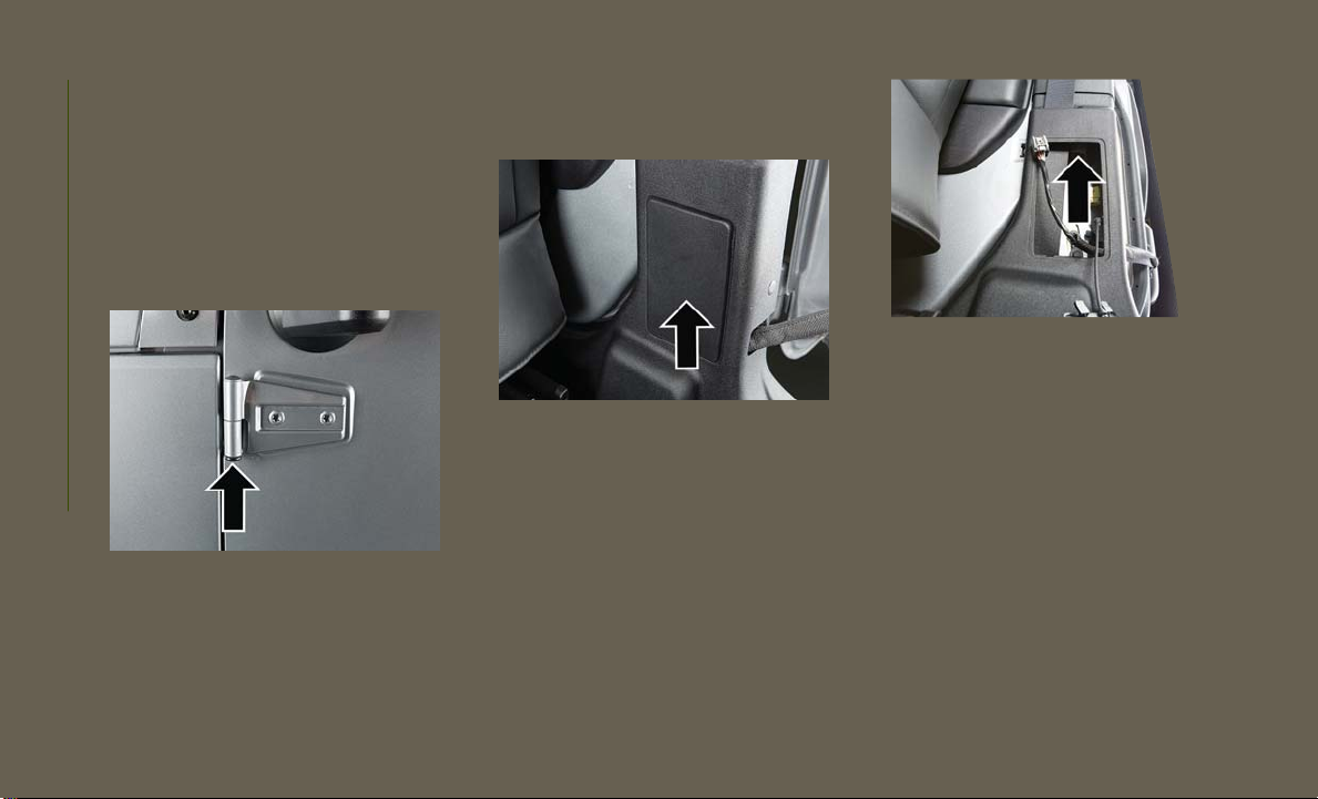
2. Remove the hinge pin screws from the
upper and lower outside hinges (using a
#T50 Torx head driver).
NOTE:
The hinge pin screws and nuts can be
stowed in the rear cargo tray located under the rear loadfloor.
Hinge Pin Screw
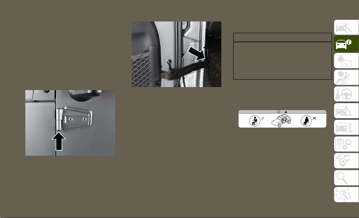
3. Unplug the wiring harness connector under the instrument panel by pushing the
tab at the base of the connector and
pulling down to disconnect.
Door Strap/Harness Location
4. Unhook the door strap from the body
hook. Be careful not to allow the door to
swing fully open as the mirror may damage the paint.
5. With the door open, lift the door to clear
the hinge pins from their hinges and remove the door.
NOTE:
Doors are heavy; use caution when removing them.
To reinstall the door(s), perform the previous
steps in the opposite order.
Rear Door Removal (Four-Door Models)
WARNING!
Do not drive your vehicle on public roads
with the doors removed as you will lose the
protection they can provide. This procedure is furnished for use during off-road
operation only.
Door Removal Warning Label
NOTE:
Hinge pin can break if overtightened during
door reinstall (Max Torque: 10 N·m / 7.5 ft· lb).
21
Page 24
1. Roll down the glass window to prevent any
damage.
2. Remove the hinge pin screws from the
upper and lower outside hinges (using a
#T50 Torx head driver).
NOTE:
The hinge pin screws and nuts can be
stowed in the rear cargo tray located under the rear load floor.
GETTING TO KNOW YOUR VEHICLE
Hinge Pin Screw
3. Slide the front seat(s) fully forward.
4. Remove the trim access door from the
bottom of the B-pillar.
Trim Access Door
5. Unplug the wiring harness connector.
NOTE:
Squeeze the tab on the base of the connector. This will unlock the connector
tab, allowing the harness to be disconnected.
Connector Unplugged
6. Unhook the door strap from the body
hook.
7. With the door open, lift the door to clear
the hinge pins from their hinges and remove the door.
NOTE:
Doors are heavy; use caution when removing
them.
To reinstall the door(s), perform the previous
steps in the opposite order.
22
Page 25
SEATS
Seats are a part of the Occupant Restraint
System of the vehicle.
WARNING!
• It is dangerous to ride in a cargo area,
inside or outside of a vehicle. In a collision, people riding in these areas are
more likely to be seriously injured or
killed.
• Do not allow people to ride in any area of
your vehicle that is not equipped with
seats and seat belts. In a collision,
people riding in these areas are more
likely to be seriously injured or killed.
• Be sure everyone in your vehicle is in a
seat and using a seat belt properly.
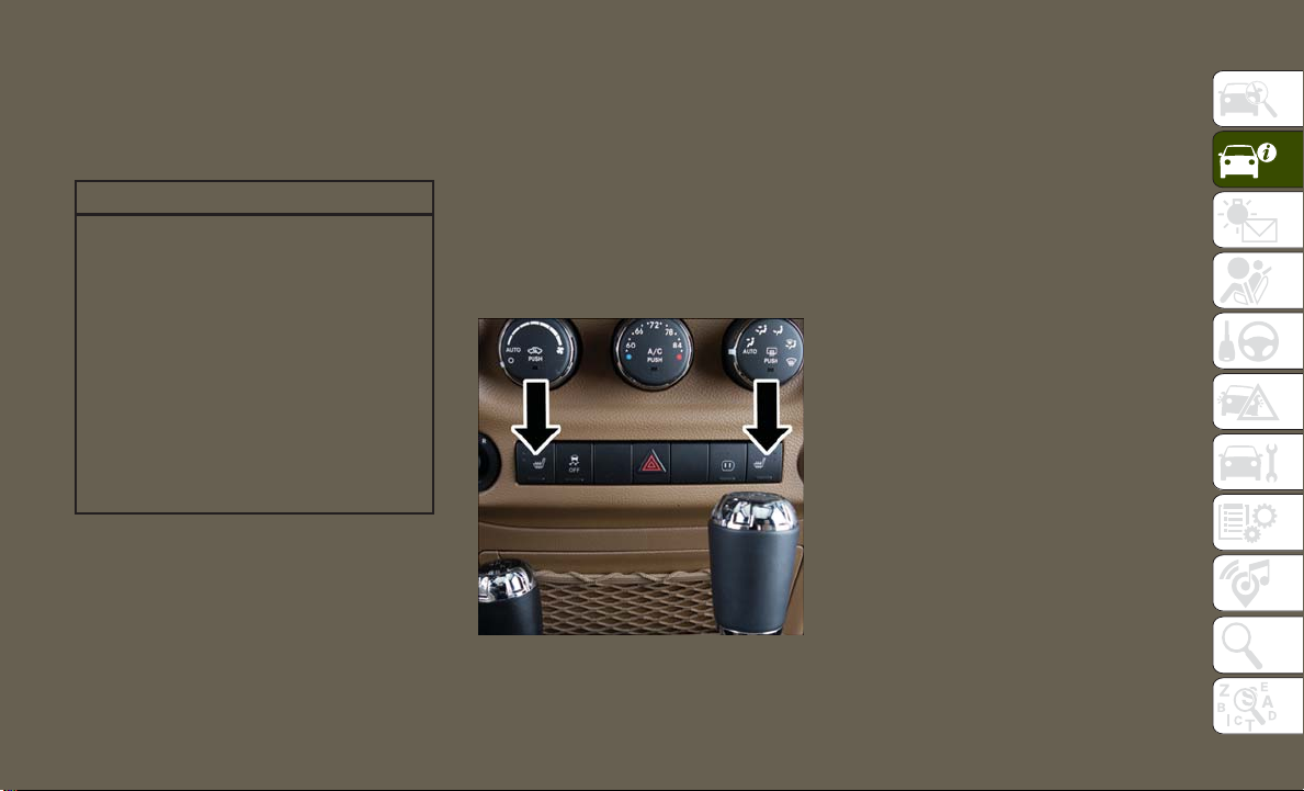
Heated Seats — If Equipped
On some models, the front driver and passenger seats may be equipped with heaters in
both the seat cushions and seatbacks.
There are two heated seat switches that allow
the driver and passenger to operate the seats
independently. The controls for each seat are
located on a switch bank near the bottom
center of the instrument panel.
Front Heated Seat Switches
You can choose from HI, LO or OFF heat
settings. Amber indicator lights in each
switch indicate the level of heat in use. Two
indicator lights will illuminate for HI, one for
LO and none for OFF.
Push the switch once to select HI-level heating. Push the switch a second time to select
LO-level heating. Push the switch a third time
to shut the heating elements OFF.
When the HI-level setting is selected, the
heater will provide a boosted heat level during the initial stages of operation. Then, the
heat output will drop to the normal HI-level.
If the HI-level setting is selected, the system
will automatically switch to LO-level after
approximately 30 minutes of continuous operation. At that time, the number of illuminated LEDs changes from two to one, indicating the change. The LO-level setting will turn
OFF automatically after approximately
30 minutes.
NOTE:
When a heat setting is selected, heat will be
felt within two to five minutes.
23
Page 26

WARNING!
• Persons who are unable to feel pain to
the skin because of advanced age,
chronic illness, diabetes, spinal cord injury, medication, alcohol use, exhaustion or other physical condition must
exercise care when using the seat
heater. It may cause burns even at low
temperatures, especially if used for long
periods of time.
• Do not place anything on the seat or
seatback that insulates against heat,
such as a blanket or cushion. This may
cause the seat heater to overheat. Sitting in a seat that has been overheated
could cause serious burns due to the
increased surface temperature of the
GETTING TO KNOW YOUR VEHICLE
seat.
24
60/40 Split Folding Rear Seat —
Four Door Models
To provide additional storage area, each rear
seat can be folded flat to allow for extended
cargo space.
NOTE:
• Prior to folding the rear seat, it may be
necessary to reposition the front seat to its
mid-track position.
• Be sure that the front seats are fully upright
and positioned forward. This will allow the
rear seat to fold down easily.
WARNING!
• It is extremely dangerous to ride in a
cargo area, inside or outside of a vehicle.
In a collision, people riding in these
areas are more likely to be seriously
injured or killed.
• Do not allow people to ride in any area of
your vehicle that is not equipped with
seats and seat belts.
• Be sure everyone in your vehicle is in a
seat and using a seat belt properly.
To Fold Down The Rear Seat
Locate the release lever (upper outboard side
of seat), and lift it upward until the seatback
releases.
Slowly fold down the seatback.
NOTE:
You may experience deformation in the seat
cushion from the seat belt buckles if the
seats are left folded for an extended period of
time. This is normal. By simply opening the
seats to the open position, the seat cushion
will return to its normal shape over time.
To Raise The Rear Seat
Raise the seatback and lock it into place. If
interference from the cargo area prevents the
seatback from fully locking, you will have
difficulty returning the seat to its proper
position.
NOTE:
If the rear seatback is not fully latched, the
center shoulder belt will not be able to be
extended for use. If you cannot extend the
center shoulder belt, make sure your seatback is fully latched.
Page 27
WARNING!
Be certain that the seatback is securely
locked into position. If the seatback is not
securely locked into position the seat will
not provide the proper stability for child
seats and/or passengers. An improperly
latched seat could cause serious injury.
• The recliner and easy entry levers should
not be used during the automatic returning
of the seat to its sitting position.
Tip ‘n Slide Seats — Two Door Models
This feature allows the front seats to be
rotated toward the instrument panel to allow
easier entry into the rear seats.
Front Passenger Easy Entry Seat — Two
Door Models
Pull upward on the recline lever (toward the
rear of the vehicle) and slide the entire seat
forward.
Easy Entry Lever
To return the seat to a sitting position, rotate
the seatback upright until it locks and push
the seat rearward until the track locks.
NOTE:
• The front passenger seats have a track
memory, which returns the seat to just past
the halfway point of the track regardless of
its original position.
Driver's Seat
Pull upward on the recline lever and bring the
seatback to its full forward position.
Rotate the entire seat assembly toward the
instrument panel.
Passenger Seat
In addition to Easy Entry, the front passenger
seat is also equipped with Tip ‘n Slide. This
feature allows for easier entry for rear passengers.
Pull upward on the recline lever and slide the
entire seat forward (Easy Entry).
With the seat forward, pull the entire seat
assembly toward the instrument panel.
25
Page 28
Removing The Rear Seat —
Two Door Models
NOTE:
• Prior to folding the rear seat, it may be
necessary to reposition the front seats.
• Be sure that the front seats are fully upright
and positioned forward. This will allow the
rear seat to fold down easily.
1. Lift the seatback release lever and fold
the seatback forward.
2. Slowly flip the entire seat forward.
WARNING!
Do not drive the vehicle with the seat in
the forward tumble position. The seat
must be latched to all floor attachments
when the vehicle is in motion.
3. Push down on the release bar on each
side, and pull the seat out and away from
the lower bracket.
4. Remove the seat from the vehicle.
WARNING!
• In a collision, you or others in your
vehicle could be injured if seats are not
properly latched to their floor attachments. Always be sure that the seats are
fully latched.
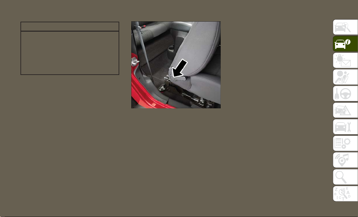
Replacing The Rear Seat —
Two Door Models
Reverse the steps for removing the seat.
WARNING!
GETTING TO KNOW YOUR VEHICLE
26
Seatback Release Lever
WARNING!
• It is extremely dangerous to ride in a
cargo area, inside or outside of a vehicle.
In a collision, people riding in these
areas are more likely to be seriously
injured or killed.
• Do not allow people to ride in any area of
your vehicle that is not equipped with
seats and seat belts.
• Be sure everyone in your vehicle is in a
seat and using a seat belt properly.
• To help protect against personal injury,
passengers should not be seated in the
rear cargo area with the rear seat folded
down or removed from the vehicle.
• The rear cargo space is intended for load
carrying purposes only, not for passengers who should sit in seats and use seat
belts.
Page 29
HEAD RESTRAINTS
Head restraints are designed to reduce the
risk of injury by restricting head movement in
the event of a rear impact. Head restraints
should be adjusted so that the top of the head
restraint is located above the top of your ear.
WARNING!
• All occupants, including the driver,
should not operate a vehicle or sit in a
vehicle’s seat until the head restraints
are placed in their proper positions in
order to minimize the risk of neck injury
in the event of a crash.
• Head restraints should never be adjusted while the vehicle is in motion.
Driving a vehicle with the head restraints
improperly adjusted or removed could
cause serious injury or death in the event
of a collision.
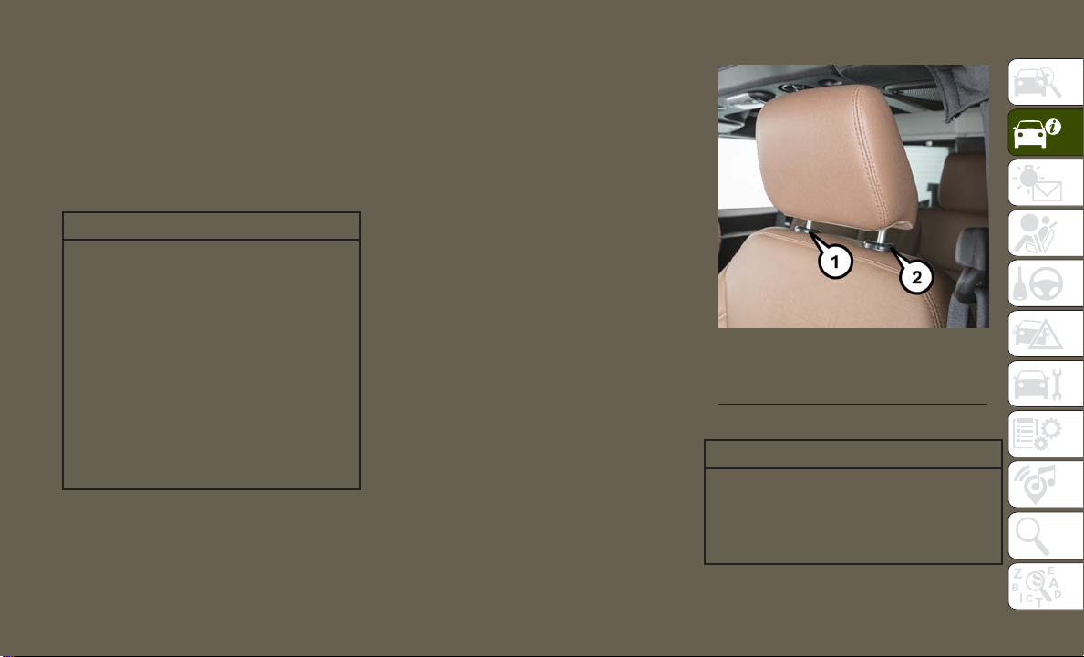
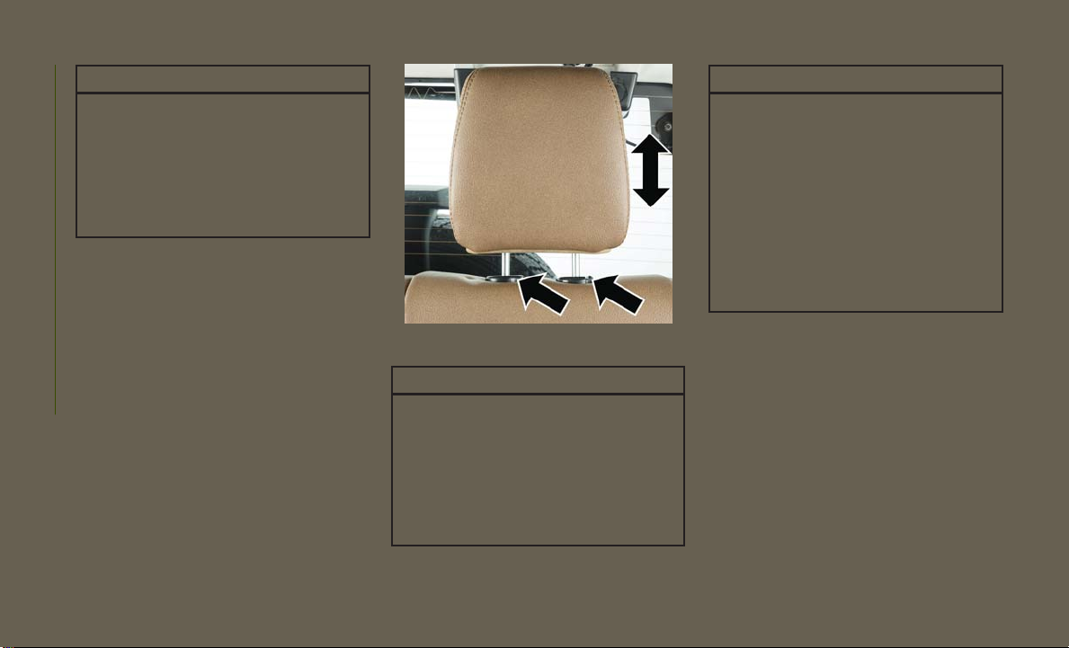
Front Head Restraints
To raise the head restraint, pull upward on the
head restraint. To lower the head restraint,
push the adjustment button located on the
base of the head restraint, and push downward on the head restraint.
To remove the head restraint, raise it as far as
it can go then push the adjustment button
and the release button at the base of each
post while pulling the head restraint up. To
reinstall the head restraint, put the head
restraint posts into the holes and push downward. Then adjust it to the appropriate
height.
Front Head Restraint
1 — Release Button
2 — Adjustment Button
WARNING!
• A loose head restraint thrown forward in
a collision or hard stop could cause serious injury or death to occupants of the
vehicle. Always securely stow removed
27
Page 30
WARNING!
head restraints in a location outside the
occupant compartment.
• ALL the head restraints MUST be reinstalled in the vehicle to properly protect
the occupants. Follow the re-installation
instructions above prior to operating the
vehicle or occupying a seat.
NOTE:
Do not reposition the head restraint 180 degrees
to the incorrect position in an attempt to gain
additional clearance to the back of the head.
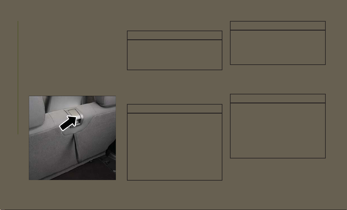
Rear Head Restraints — Two Door Model
The rear seat head restraints are not adjustable. They can be removed to make it easier
GETTING TO KNOW YOUR VEHICLE
to take out the rear seat. To remove the head
restraint, push the button on each of the two
head restraint guides and pull upward on the
head restraint. Replace the head restraint
before driving the vehicle with passengers in
the rear seat. To replace the head restraint,
insert the head restraint rods into the guides
and push downward on the head restraint
until locked.
28
Rear Head Restraint
WARNING!
• Do not drive the vehicle without the rear
seat head restraints installed while passengers are occupying the rear seat. In a
collision, people riding in this area without the head restraints installed are
more likely to be seriously injured or
killed.
WARNING!
• A loose head restraint thrown forward in
a collision or hard stop could cause
serious injury or death to occupants of
the vehicle. Always securely stow removed head restraints in a location outside the occupant compartment.
• ALL the head restraints MUST be reinstalled in the vehicle to properly protect
the occupants. Follow the reinstallation
instructions above prior to operating the
vehicle or occupying a seat.
NOTE:
Do not reposition the head restraint 180 degrees to the incorrect position in an attempt
to gain additional clearance to the back of the
head.
Rear Head Restraints — Four Door Model
The rear seat is equipped with nonadjustable
head restraints.
Page 31

STEERING WHEEL
Tilt Steering Column
This feature allows you to tilt the steering
column upward or downward. The tilt lever is
located on the steering column, below the
turn signal lever.
To Adjust The Tilt Steering Column
1. Push down on the lever to unlock the
steering column.
2. With one hand firmly on the steering
wheel, move the steering column up or
down, as desired.
3. Pull upwards on the lever to lock the
column firmly in place.
MIRRORS
Heated Mirrors — If Equipped
These mirrors are heated to melt frost or ice.
This feature will be activated whenever you
turn on the rear window defroster (if
equipped). Refer to “Climate Controls” in
“Getting To Know Your Vehicle” for further
information.
Tilt Steering Column Lever
WARNING!
Do not adjust the steering column while
driving. Adjusting the steering column
while driving or driving with the steering
column unlocked, could cause the driver
to lose control of the vehicle. Failure to
follow this warning may result in serious
injury or death.
EXTERIOR LIGHTS
Headlights And Parking Lights
Turn Signal/Lights Lever
Turn the end of the multifunction lever to the
first detent for parking light operation. Turn
to the second detent for headlight operation.
29
Page 32

Daytime Running Lights — If Equipped
The headlights come on at a low intensity
level when shifted into any position other
than PARK (auto transmission) or when the
vehicle begins to move (manual transmission).
NOTE:
The Daytime Running Light, on the same side
of the vehicle as the active turn signal, will
turn off automatically when a turn signal is in
operation and turn on again when the turn
signal is not operating.
High/Low Beam Switch
Push the multifunction lever toward the instrument panel to switch the headlights to
GETTING TO KNOW YOUR VEHICLE
high beams. Pulling the multifunction lever
back toward the steering wheel will return the
lights to low beams.
Flash-To-Pass
You can signal another vehicle with your
headlights by lightly pulling the multifunction lever toward you. This will cause the high
beam headlights to turn on, and remain on,
until the lever is released.
Automatic Headlights — If Equipped
This system automatically turns the headlights on or off according to ambient light
levels. To turn the system on, turn the end of
the multifunction lever to the AUTO position
(third detent). When the system is on, the
Headlight Time Delay feature is also on. This
means the headlights will stay on for up to
90 seconds after you turn the ignition switch
to the LOCK position. To turn the Automatic
System off, turn the end of the multifunction
lever out of the AUTO position.
NOTE:
The engine must be running before the headlights will turn on in the Automatic mode.
Front Fog Lights
The front fog light switch is located on the
multifunction lever. To activate the front fog
lights, turn on the parking or low beam headlights and pull out the end of the lever.
NOTE:
The fog lights will only operate with the
parking lights or the headlights on low beam.
Selecting high beam headlights will turn off
the fog lights.
Turn Signals
Move the multifunction lever up or down and
the arrows on each side of the instrument
cluster flash to show proper operation of the
front and rear turn signal lights.
NOTE:
• If either light remains on and does not
flash, or there is a very fast flash rate, check
for a defective outside light bulb. If an
indicator fails to light when the lever is
moved, it would suggest that the indicator
bulb is defective.
30
Page 33

• A tone will chime if the turn signals are left
on for more than 1 mile (2 km).
Lane Change Assist — If Equipped
Tap the multifunction lever up or down once,
without moving beyond the detent, and the
turn signal (right or left) will flash three times
then automatically turn off.
Lights-On Reminder
If the headlights, parking lights, or cargo
lights are left on after the ignition is turned
OFF, a chime will sound when the driver’s
door is opened.
WINDSHIELD WIPERS AND WASHERS
Wiper/Washer Lever
The windshield wiper/washer control lever is
located on the right side of the steering column. The front wipers are operated by rotating a switch, located at the end of the lever.
For information on using the rear window
wiper/washer, refer to “Rear Window Wiper/
Washer” in this section for more information.
Windshield Wiper Operation
Rotate the end of the lever upward to the
second detent past the intermittent settings
for low-speed wiper operation. Rotate the end
of the lever upward to the third detent past
the intermittent settings for high-speed wiper
operation.
CAUTION!
In cold weather, always turn off the wiper
switch and allow the wipers to return to the
park position before turning off the engine.
If the wiper switch is left on and the wipers
freeze to the windshield, damage to the
wiper motor may occur when the vehicle is
restarted.
Intermittent Wiper System
Use the intermittent wiper when weather conditions make a single wiping cycle, with a
variable pause between cycles, desirable. Rotate the end of the lever to the first detent
position for one of five intermittent settings.
The delay cycle can be set anywhere between
1 to 18 seconds.
NOTE:
The wiper delay times depend on vehicle
speed. If the vehicle is moving less than
10 mph (16 km/h), delay times will be
doubled.
Windshield Washers
To use the washer, pull the lever toward you
and hold while spray is desired. If the lever is
pulled while in the delay range, the wiper will
start and continue to operate for two or three
wipe cycles after the lever is released. Then,
the intermittent interval previously selected
will resume.
If the lever is pulled while in the off position,
the wipers will operate for two or three wipe
cycles. Then, the wipers will turn off.
31
Page 34

WARNING!
Sudden loss of visibility through the windshield could lead to a collision. You might
not see other vehicles or other obstacles.
To avoid sudden icing of the windshield
during freezing weather, warm the windshield with the defroster before and during
windshield washer use.
Mist Feature
Push down on the wiper lever to activate a
single wipe to clear off road mist or spray
from a passing vehicle. As long as the lever is
held down, the wipers will continue to operate.
NOTE:
GETTING TO KNOW YOUR VEHICLE
The mist feature does not activate the washer
pump; therefore, no washer fluid will be
sprayed on the windshield. The wash function must be used in order to spray the
windshield with washer fluid.
Rear Window Wiper/Washer —
If Equipped
A rotary switch on the center portion of the
control lever (located on the right side of the
steering column) controls the operation of
the rear wiper/washer function.
Rotate the switch upward to the first detent
position for rear wiper operation.
Rotate the switch upward past the first detent
to activate the rear washer. The washer pump
and the wiper will continue to operate as long
as the switch is held. Upon release, the wiper
will cycle two to three times before returning
to the set position.
If the rear wiper is operating when the ignition is turned to the LOCK position, the wiper
will automatically return to the “park” position. When the vehicle is restarted, the wiper
will resume function at whichever position
the switch is set at.
32
Page 35

CLIMATE CONTROLS
Automatic Climate Control Overview
Automatic Temperature Controls
33
Page 36

Automatic Climate Control Descriptions
Icon Description
A/C Button
Push the A/C button to engage the Air Conditioning (A/C). An LED will illuminate when the A/C system is engaged.
Automatic Operation
The Automatic Temperature Control system automatically maintains the climate in the cabin of the vehicle at the
comfort levels desired by the driver and passenger. Operation of the system is quite simple.
Turn the Mode Control knob (on the right) and the Blower Control knob (on the left) to AUTO.
Refer to “Automatic Operation” in this section for more information.
NOTE:
The AUTO position performs best for front seat occupants only.
Recirculation Button
Push and release this button to change the system between recirculation mode and outside air mode. Recirculation
can be used when outside conditions such as smoke, odors, dust, or high humidity are present.
NOTE:
GETTING TO KNOW YOUR VEHICLE
• Continuous use of the Recirculation mode may make the inside air stuffy and window fogging may occur.
Extended use of this mode is not recommended.
• The use of the Recirculation mode in cold or damp weather could cause windows to fog on the inside, because of
moisture buildup inside the vehicle. Select the outside air position for maximum defogging.
• Recirculation can be used in all modes except for Defrost.
• The A/C can be deselected manually without disturbing the mode control selection.
34
Page 37

Icon Description
Rear Defrost Button
Push and release the Rear Defrost Control button to turn on the rear window defroster and the heated outside mirrors (if
equipped). An indicator will illuminate when the rear window defroster is on. The rear window defroster automatically
turns off after ten minutes.
Temperature Control
Use this control to regulate the temperature of the air inside the passenger compartment. Rotating the knob counterclockwise, from top center into the blue area of the scale, indicates cooler temperatures. Rotating the knob clockwise,
into the red area, indicates warmer temperatures.
Blower Control
There are seven blower speeds. Use this control to regulate the amount of air forced through the system in any mode
you select. The blower speed increases as you move the control clockwise from the off position.
NOTE:
Depending on the configuration, your vehicle may be equipped with four blower speeds.
Modes Control
Turn the knob to adjust airflow distribution. The airflow distribution mode can be adjusted so air comes from the
instrument panel outlets, floor outlets, defrost outlets and demist outlets. The Mode settings are as follows:
Panel Mode
Panel Mode
Air comes from the outlets in the instrument panel. Each of these outlets can be individually adjusted to direct the flow
of air. The air vanes of the center outlets and outboard outlets can be moved up and down or side to side to regulate
airflow direction.
35
Page 38

Icon Description
Bi-Level Mode
Floor Mode
Bi-Level Mode
Air comes from the instrument panel outlets and floor outlets. A slight amount of air is directed through the defrost and
side window demister outlets.
NOTE:
Bi-Level mode is designed under comfort conditions to provide cooler air out of the panel outlets and warmer air from
the floor outlets.
Floor Mode
Air comes from the floor outlets. A slight amount of air is directed through the defrost and side window demister
outlets.
Front Defrost Mode
GETTING TO KNOW YOUR VEHICLE
36
Mix Mode
Mix Mode
Air is directed through the floor, defrost, and side window demister outlets. This setting works best in cold or snowy
conditions that require extra heat to the windshield. This setting is good for maintaining comfort while reducing
moisture on the windshield.
Front Defrost Mode
Turn the knob to the Front Defrost position. Air comes from the windshield and side window demist outlets. When the
defrost mode is selected, the blower level will increase. Use Defrost mode with maximum temperature settings for best
windshield and side window defrosting and defogging.
Page 39

Automatic Temperature Control (ATC) —
If Equipped
Automatic Operation
1. Push the AUTO button on the faceplate on
the Automatic Temperature Control (ATC)
Panel.
2. Next, adjust the temperature you would
like the system to maintain by adjusting
the driver and passenger temperature
control buttons. Once the desired temperature is displayed, the system will
achieve and automatically maintain that
comfort level.
3. When the system is set up for your comfort
level, it is not necessary to change the
settings. You will experience the greatest
efficiency by simply allowing the system
to function automatically.
NOTE:
• It is not necessary to move the temperature
settings for cold or hot vehicles. The system
automatically adjusts the temperature,
mode, and blower speed to provide comfort
as quickly as possible.
To provide you with maximum comfort in the
Automatic mode during cold start-ups, the
blower fan will remain on low until the engine
warms up. The blower will increase in speed
and transition into Auto mode.
Manual Operation Override
This system offers a full complement of
manual override features. The AUTO symbol
in the front ATC display will be turned off
when the system is being used in the manual
mode.
Operating Tips
Summer Operation
The engine cooling system must be protected
with a high-quality antifreeze coolant to provide proper corrosion protection and to protect against engine overheating. OAT coolant
(conforming to MS.90032) is recommended.
Winter Operation
To ensure the best possible heater and defroster performance, make sure the engine
cooling system is functioning properly and
the proper amount, type, and concentration
of coolant is used. Use of the Air Recirculation mode during Winter months is not recommended, because it may cause window
fogging.
Vacation/Storage
Before you store your vehicle, or keep it out of
service (i.e., vacation) for two weeks or more,
run the air conditioning system at idle for
about five minutes, in fresh air with the
blower setting on high. This will ensure adequate system lubrication to minimize the
possibility of compressor damage when the
system is started again.
Window Fogging
Vehicle windows tend to fog on the inside in
mild, rainy, and/or humid weather. To clear
the windows, select Defrost or Mix mode and
increase the front blower speed. Do not use
the Recirculation mode without A/C for long
periods, as fogging may occur.
37
Page 40

CAUTION!
Failure to follow these cautions can cause
damage to the heating elements:
• Use care when washing the inside of
the rear window. Do not use abrasive
window cleaners on the interior surface
of the window. Use a soft cloth and a
mild washing solution, wiping parallel
to the heating elements. Labels can be
peeled off after soaking with warm
water.
• Do not use scrapers, sharp instruments, or abrasive window cleaners on
the interior surface of the window.
• Keep all objects a safe distance from
the window.
GETTING TO KNOW YOUR VEHICLE
Outside Air Intake
Make sure the air intake, located directly in
front of the windshield, is free of obstructions, such as leaves. Leaves collected in the
air intake may reduce airflow, and if they
enter the plenum, they could plug the water
drains. In Winter months, make sure the air
intake is clear of ice, slush, and snow.
Cabin Air Filter
The climate control system filters out dust
and pollen from the air. Contact an authorized dealer to service your cabin air filter,
and to have it replaced when needed.
POWER WINDOWS — IF EQUIPPED
The power window switches are located on
the instrument panel below the radio. Push
the switch downward to open the window and
upward to close the window.
The top left switch controls the left front
window and the top right switch controls the
right front window.
WARNING!
Never leave children unattended in a vehicle, and do not let children play with
power windows. Do not leave the key fob in
or near the vehicle, or in a location accessible to children. Occupants, particularly
unattended children, can become entrapped by the windows while operating
the power window switches. Such entrapment may result in serious injury or death.
Power Window Switches
38
Page 41

NOTE:
• For vehicles not equipped with the instrument cluster display, the power window
switches will remain active for 45 seconds
after the ignition switch is turned to the
LOCK position. Opening either front door
will cancel this feature.
• For vehicles equipped with the instrument
cluster display, the power window switches
will remain active for up to 10 minutes after
the ignition switch is turned to the LOCK
position. Opening either front door will cancel this feature.
Four-Door Models
The lower left switch controls the left rear
passenger window, and the lower right switch
controls the right rear passenger window.
Wind Buffeting
Wind buffeting can be described as the perception of pressure on the ears or a
helicopter-type sound in the ears. Your vehicle may exhibit wind buffeting with the
windows down in certain open or partially
open positions. This is a normal occurrence
and can be minimized by adjusting the window opening.
REMOVABLE TOP INFORMATION
Please visit http://www.jeep.com/en/wranglerrooftop-instructions/ for instructional videos.
For complete information, refer to your Owner's
Manual.
Sunrider And Soft Top
Two-Door Sunrider Open
Follow these simple steps to open the Sunrider feature.
1. Unclip and move the sun visors to the
side.
2. Release the header latches from the loops
on the windshield frame.
Step 2
39
Page 42

3. Make sure to slide the plastic sleeves
forward to unlock the Sunrider links.
4. Grasp the header and lift the top back.
Make sure the material is folded back as
shown.
Step 5
GETTING TO KNOW YOUR VEHICLE
40
Step 3
Step 4
5. Locate the straps to secure the side bows.
Wrap the straps around the bows as
shown. Repeat on the other side.
6. Reposition the sun visors.
NOTE:
If you are going to be driving faster than
40 mph (64 km/h) with the Sunrider feature
open, it is recommended that you remove the
rear window of the vehicle.
• To close the Sunrider feature, perform the
above steps in the opposite order.
Page 43

Two-Door Soft Top Down
Follow these simple steps to lower the TwoDoor soft top.
1. Remove the side and back windows.
Step 1
2. Fold and place the Sail Panels on top of
your Wrangler.
Step 2 Step 3
3. Release header latches from the windshield frame.
41
Page 44

4. Make sure the plastic sleeves are slid
rearward over the Sunrider link to lock in
the link (Sunrider Models only).
5. Release the Sunrider latch (both sides). 6. Open the swing gate and lower the top.
Step 5 Step 6
GETTING TO KNOW YOUR VEHICLE
42
Step 4
NOTE:
Ensure the fabric does not overhang the sides
of the vehicle.
• To raise the soft top, perform the above
steps in the opposite order.
Page 45

Four-Door Sunrider Down
Follow these simple steps to open the Sunrider feature.
1. Unclip and move the sun visors to the
side.
2. Release the header latches from the loops
on the windshield frame.
Step 2
3. Grasp the front side bow behind the
header, and lift the top.
Step 3
4. Fold the top so that the material forms a
"W" as shown. Enter the vehicle and move
the material into two folds.
Step 4
43
Page 46

5. Fold back the front section of the top and
gently rest the header on top of the rear
portion of the deck.
GETTING TO KNOW YOUR VEHICLE
6. Secure the top by using the two provided
straps. Each strap will wrap around the
side bow and Velcro to itself; use one strap
on each side of the vehicle.
Step 5
Step 6
NOTE:
• Failure to fold the fabric rearward will allow
the material to sag and may block the
rearview mirror.
• If you are going to be driving faster than
40 mph (64 km/h) with the Sunrider feature open, it is recommended that you
remove the rear window of the vehicle.
• To close the Sunrider feature, perform the
above steps in the opposite order.
Four-Door Soft Top Down
Follow these simple steps to lower the FourDoor soft top.
1. Remove the side and back windows.
Step 1
44
Page 47

2. Fold and place the Sail Panels on top of
your Wrangler.
Step 2 Step 3 Step 4
3. Release header latches from the windshield frame.
4. Fold header rearward, pulling the fabric to
the rear.
45
Page 48

5. Fold the top so that the material forms a
"W" as shown. Enter the vehicle and move
the material into two folds.
6. Release the side bows by pushing down
on the latch above the front of the rear
doors.
7. Push the top rearward to disengage.
Step 7
GETTING TO KNOW YOUR VEHICLE
46
Step 5 Step 6
Page 49

8. Open the swing gate and lower the top.
Step 8
NOTE:
Ensure the fabric does not overhang the sides
of the vehicle.
• To raise the soft top, perform the above
steps in the opposite order.
WARNING!
• Do not drive the vehicle with the rear
window curtain up unless the side curtains are also open. Dangerous exhaust
gases which can kill could enter the
vehicle.
• The fabric upper doors and fabric top are
designed only for protection against the
elements. Do not rely on them to contain
occupants within the vehicle or to protect against injury during an accident.
Remember, always wear seat belts.
CAUTION!
• Do not run a fabric top through an automatic car wash. Window scratches and
wax buildup may result.
• Do not lower the top when the temperature is below 41°F (5°C). Damage to the
top may result.
• Do not lower the top when the windows
are dirty. Grit may scratch the window.
CAUTION!
• Do not move your vehicle until the top
has been either fully attached to the
windshield frame, or fully lowered.
• The soft top is not designed to carry any
additional loads such as roof racks,
spare tires, building, hunting, or camping supplies, and/or luggage, etc. Also, it
was not designed as a structural member
of the vehicle and, thus, cannot properly
carry any additional loads other than
environmental (rain, snow, etc.).
Hard Top And Freedom Top
Freedom Top Removal
Follow these simple steps to remove the front
panels.
1. Fold down the sun visor, and move it to the
side.
47
Page 50

2. Turn the rear fasteners (located on the
overhead speaker bar assembly) counterclockwise until they can be removed.
GETTING TO KNOW YOUR VEHICLE
Step 2
3. Turn the center L-shaped locks (two) from
the center of the roof panel.
Step 3 Step 4
4. Turn the rear L-shaped lock (located
above the shoulder belt anchorage).
48
Page 51

5. Unlatch the header panel latches located
at the top of the windshield.
Step 5
6. Remove the left-hand panel.
To remove the right panel, follow the steps
above except for step three.
NOTE:
• The left panel must be removed before
removing right panel.
• Vehicles equipped with a Freedom Top,
come with a Freedom Top storage bag that
allows you to store your Freedom Top
panels.
For complete information, refer to your Owner's
Manual.
Hard Top Removal
Follow these simple steps to remove the hard
top.
1. Remove both front panels. Refer to “Free-
dom Top Removal” in the previous
section.
2. Open both doors.
3. Remove the two Torx head screws that
secure the hard top at the B-pillar (near
the top of the door) using a #40 Torx head
driver (Four–Door Only).
4. Remove the six Torx head screws that
secure the hard top to the vehicle (along
the interior body side) using a #40 Torx
head driver.
5. Open the swing gate all the way to ensure
clearance of the rear window glass. Lift
the rear window glass.
6. Locate and disconnect the wire harness
on the left rear inside corner of the
vehicle.
Step 6
7. Remove the washer hose (next to the wire
harness) by pinching the grips on hose
connector and pull downward.
8. Close the swing gate.
9. Remove the hard top from the vehicle.
Place the hard top on a soft surface to
prevent damage.
49
Page 52

CAUTION!
• The front panel(s) must be positioned
properly to ensure sealing. Improper installation can cause water to leak into
the vehicle's interior.
• The hard top assembly must be positioned properly to ensure sealing. Improper installation can cause water to
leak into the vehicle's interior.
• The hard top is not designed to carry any
additional loads such as roof racks,
spare tires, building, hunting, or camping supplies, and/or luggage, etc. Also, it
was not designed as a structural member of the vehicle, and thus cannot properly carry any additional loads other than
environmental (rain, snow, etc.).
GETTING TO KNOW YOUR VEHICLE
• Do not move your vehicle until the top
has been either fully attached to the
windshield frame and bodyside, or fully
removed.
• The removal of the hard top requires four
adults located on each corner. Failure to
follow this caution could damage the
hard top.
Dual Top — If Equipped
If your vehicle is equipped with a Dual Top,
you must remove one of the tops from the
vehicle.
• Two Door - If the soft top is removed, the
pivot brackets must also be removed from
the sport bar.
• Four Door - If the soft top is removed, ensure
that the pivot bracket strap is installed onto
the Soft Top pivot bracket before removing the
soft top from the vehicle. Remove the fasten-
ers between the Soft Top pivot bracket and
the attach bracket to the sport bar.
Pivot Bracket Strap
NOTE:
• The soft top was installed at the factory for
shipping purposes only.
• The soft top and the hard top are to be used
independently.
• For complete information, refer to your Own-
er's Manual.
50
Page 53

Wind Buffeting
Wind buffeting can be described as a
helicopter-type percussion sound. If buffeting occurs with the rear windows open, adjust
the front and rear windows together.
HOOD
Opening The Hood
Release both the hood latches.
Hood Latch Location
Raise the hood and locate the safety latch,
located in the middle of the hood opening.
Push the safety latch to the left side of the
vehicle, to open the hood. You may have to
push down slightly on the hood before pushing the safety latch. Insert the support rod
into the slot on the hood.
Closing The Hood
To close the hood, remove the support rod
from the hood panel and place it in the
retaining clip. Lower the hood slowly. Secure
both of the hood latches.
WARNING!
Be sure the hood is fully latched before
driving your vehicle. If the hood is not fully
latched, it could open when the vehicle is
in motion and block your vision. Failure to
follow this warning could result in serious
injury or death.
REAR SWING GATE
The rear swing gate can be unlocked by using
the key, Remote Keyless Entry key fob, or by
activating the power door lock switches located on the front doors.
To open the swing gate, push the button on
the gate handle.
Swing Gate Handle
NOTE:
Close the rear flip-up window before attempting to close the swing gate (hard top models
only).
51
Page 54

WARNING!
Driving with the flip-up window open can
allow poisonous exhaust gases into your
vehicle. You and your passengers could be
injured by these fumes. Keep the flip-up
window closed when you are operating the
vehicle.
CAUTION!
Do not push on rear wiper blade when
closing the rear flip-up window, as damage
to the blade will result.
GETTING TO KNOW YOUR VEHICLE
INTERNAL EQUIPMENT
Power Outlets
There are three possible 12 Volt Power Outlets in this vehicle.
• The front 12 Volt power outlet is located
below the climate controls in the Center
Console, and is powered when the ignition
switch is in the ON/RUN position. The
outlet can operate a conventional cigar
lighter unit or power accessories designed
for use with a standard power outlet
adapter.
Power Outlet — Front
• The center console 12 Volt power outlet is
powered directly from the battery (power
available at all times). Items plugged into
this outlet may discharge the battery and/or
prevent the engine from starting.
Power Outlet — Center Console
52
Page 55

• On vehicles equipped with a rear subwoofer, there is also a 12 Volt power outlet
located in the rear cargo area of the vehicle.
This power outlet has power available directly from the battery (power available at
all times). Items plugged into this outlet
also may discharge the battery and/or prevent the engine from starting.
Power Outlet — Rear Cargo Area
NOTE:
• Do not exceed the maximum power of
160 Watts (13 Amps) at 12 Volts. If the
160 Watt (13 Amp) power rating is exceeded the fuse protecting the system will
need to be replaced.
• Power outlets are designed for accessory
plugs only. Do not insert any other object in
the power outlet as this will damage the
outlet and blow the fuse. Improper use of
the power outlet can cause damage not
covered by your new vehicle warranty.
53
Page 56

1 — #M7 Fuse 20 Amp Yellow – Power Outlet Rear (If Equipped)
GETTING TO KNOW YOUR VEHICLE
2 — #M6 Fuse 20 Amp Yellow – Cigar Lighter Instrument Panel
3 — #M36 Fuse 20 Amp Yellow – Power Outlet Console Bin
54
Power Outlet Fuses
Page 57

Power Inverter — If Equipped
Power Inverter
• A 115 Volt, 150 Watt AC power inverter is
located on the front of the center console.
• This outlet can power cellular phones, electronics and other low power devices requiring power up to 150 Watts.
• The power inverter switch is located on the
instrument panel below the climate controls. To turn on the power outlet, push the
switch once. The indicator light will illuminate. Push the switch a second time to turn
the power inverter outlet off.
NOTE:
The power inverter is designed with built-in
overload protection. If the power rating of
150 Watts is exceeded, the power inverter
will automatically shut down. Once the electrical device has been removed from the outlet, the inverter should automatically reset. If
the power rating exceeds approximately
170 Watts, the power inverter may have to be
reset manually. To reset the inverter manually, unplug the device and plug it in again. To
avoid overloading the circuit, check the
power ratings on electrical devices prior to
using the inverter.
WARNING!
To Avoid Serious Injury or Death DO NOT:
• insert any objects into the receptacles
• touch with wet hands
Close the lid when not in use. If this outlet
is mishandled, it may cause an electric
shock and failure.
55
Page 58

56
Page 59

GETTING TO KNOW YOUR INSTRUMENT PANEL
GETTINGTO KNOW YOUR INSTRUMENT PANEL
INSTRUMENT CLUSTER DISPLAY —
IFEQUIPPED................58
Instrument Cluster Display Location
And Controls ..................58
Instrument Cluster Display Messages . . .59
Oil Change Required .............60
WARNING LIGHTS AND
MESSAGES.................60
Red Warning Lights ..............60
Yellow Warning Lights ............63
Yellow Indicator Lights ............65
Green Indicator Lights ............66
White Indicator Lights ............66
Blue Indicator Lights .............66
ONBOARD DIAGNOSTIC SYSTEM —
OBDII ....................66
Onboard Diagnostic System (OBD II)
Cybersecurity .................67
Loose Fuel Filler Cap Message .......67
57
Page 60

INSTRUMENT CLUSTER DISPLAY — IF EQUIPPED
Your vehicle may be equipped with an instrument cluster display, which offers useful information to the driver. With the ignition in
the STOP/OFF mode, opening/closing of a
door will activate the display for viewing, and
display the total miles, or kilometers, in the
odometer. Your instrument cluster display is
designed to display important information
about your vehicle’s systems and features.
Using a driver interactive display located on
the instrument panel, your instrument cluster display can show you how systems are
working and give you warnings when they
aren’t. The steering wheel mounted controls
allow you to scroll through and enter the main
menus and submenus. You can access the
specific information you want and make selections and adjustments.
GETTING TO KNOW YOUR INSTRUMENT PANEL
Instrument Cluster Display Location And
Controls
The instrument cluster display features a
driver-interactive display that is located in
the instrument cluster.
Instrument Cluster Display
This system conveniently allows the driver to
select a variety of useful information by pushing the switches mounted on the steering
wheel.
The instrument cluster display consists of the
following:
• Compass Heading
(N, S, E, W, NE, NW, SE, SW)
• Outside Temperature (°F or °C)
• ECO Display
• Digital Speedometer
• Average Fuel Economy
• Distance To Empty
• Tire Pressure Monitor System —
If Equipped
• Elapsed Time
• Vehicle Info
• Units Selection
• System Status and Warnings
(Door Open, etc.)
• Personal Settings
(Customer-Programmable Features)
58
Page 61

The system allows the driver to select information by pushing the following buttons
mounted on the steering wheel:
Instrument Cluster Display Control Buttons
1 — MENU Button
2 — Right Arrow Button
3 — Down Arrow Button
4 — Compass Button
• Push the MENU button to scroll through the
main menus (Speedometer, Fuel Economy,
Miles To Empty, Tire Pressure, Warnings,
Timer, Vehicle Info, Units, System Warning,
Personal Settings) or to exit submenus.
• Push the right arrow button for access to
main menus, submenus or to select a personal setting in the setup menu.
• Push the compass button to display one of
eight compass readings and the outside
temperature or to exit sub menus.
• Push the down arrow button to scroll down-
ward through the submenus.
Instrument Cluster Display Messages
When the appropriate conditions exist, the
instrument cluster will display the following
messages:
• Low Tire Pressure
• Low Fuel
• Service TPM System (refer to "Tire Pressure
Monitoring System" in "Safety" for further
information)
• Damaged Key
• Key In Ignition
• Turn Signal On (with a continuous warning
chime)
• Left Front Turn Signal Lamp Out (with a
single chime)
• Left Rear Turn Signal Lamp Out (with a
single chime)
• Right Front Turn Signal Lamp Out (with a
single chime)
• Right Rear Turn Signal Lamp Out (with a
single chime)
• Key Fob Battery Low (with a single chime)
• Personal Settings Not Avail. – Vehicle Not
in Park — automatic transmission
• Personal Settings Not Avail. – Vehicle in
Motion — manual transmission
• Door Open (with vehicle graphic showing
which door is open. A single chime sounds
if the vehicle is in motion)
• Gate Open (with vehicle graphic showing
the Liftgate/back door open and a single
chime sounds if the vehicle is in motion)
59
Page 62

• Check Gascap (refer to “Refueling The Vehicle” in “Starting And Operating” for further information)
• Oil Change Required (with a single chime)
• ECO (Fuel Saver Indicator) — if equipped
Oil Change Required
Your vehicle is equipped with an engine oil
change indicator system. The “Oil Change
Required” message will display in the instrument cluster display for approximately
10 seconds after a single chime has sounded
to indicate the next scheduled oil change
interval. The engine oil change indicator system is duty cycle based, which means the
engine oil change interval may fluctuate dependent upon your personal driving style.
Unless reset, this message will continue to
display each time you turn the ignition switch
to the ON position. To turn off the message
temporarily, push and release the MENU button. To reset the oil change indicator system
(after performing the scheduled maintenance), perform the following procedure:
GETTING TO KNOW YOUR INSTRUMENT PANEL
1. Turn the ignition switch to the ON posi-
tion. Do not start the engine.
60
2. Fully push the accelerator pedal slowly
three times within 10 seconds.
3. Turn the ignition switch to the LOCK
position.
NOTE:
If the indicator message illuminates when
you start the vehicle, the oil change indicator
system did not reset. If necessary, repeat this
procedure.
WARNING LIGHTS AND MESSAGES
The warning/indicator lights will illuminate in
the instrument panel together with a dedicated message and/or acoustic signal when
applicable. These indications are indicative
and precautionary and as such must not be
considered as exhaustive and/or alternative
to the information contained in the Owner’s
Manual, which you are advised to read carefully in all cases. Always refer to the information in this chapter in the event of a failure
indication. All active telltales will display first
if applicable. The system check menu may
appear different based upon equipment options and current vehicle status. Some telltales are optional and may not appear.
Red Warning Lights
— Air Bag Warning Light
This light indicates a fault with the air bag,
and will turn on for four to eight seconds as a
bulb check when the ignition is placed in the
ON/RUN or ACC/ON/RUN position. This light
will illuminate with a single chime when a
fault with the air bag has been detected, it
will stay on until the fault is cleared. If the
light is either not on during startup, stays on,
or turns on while driving, have the system
inspected at an authorized dealer as soon as
possible.
— Brake Warning Light
This light monitors various brake functions,
including brake fluid level and parking brake
application. If the brake light turns on it may
indicate that the parking brake is applied,
that the brake fluid level is low, or that there
is a problem with the anti-lock brake system
reservoir.
Page 63

If the light remains on when the parking
brake has been disengaged, and the fluid
level is at the full mark on the master cylinder
reservoir, it indicates a possible brake hydraulic system malfunction or that a problem
with the Brake Booster has been detected by
the Anti-Lock Brake System (ABS) / Electronic Stability Control (ESC) system. In this
case, the light will remain on until the condition has been corrected. If the problem is
related to the brake booster, the ABS pump
will run when applying the brake, and a brake
pedal pulsation may be felt during each stop.
The dual brake system provides a reserve
braking capacity in the event of a failure to a
portion of the hydraulic system. A leak in
either half of the dual brake system is indicated by the Brake Warning Light, which will
turn on when the brake fluid level in the
master cylinder has dropped below a specified level.
The light will remain on until the cause is
corrected.
NOTE:
The light may flash momentarily during sharp
cornering maneuvers, which change fluid
level conditions. The vehicle should have
service performed, and the brake fluid level
checked.
If brake failure is indicated, immediate repair
is necessary.
WARNING!
Driving a vehicle with the red brake light
on is dangerous. Part of the brake system
may have failed. It will take longer to stop
the vehicle. You could have a collision.
Have the vehicle checked immediately.
Vehicles equipped with the Anti-Lock Brake
System (ABS) are also equipped with Electronic Brake Force Distribution (EBD). In the
event of an EBD failure, the Brake Warning
Light will turn on along with the ABS Light.
Immediate repair to the ABS system is required.
Operation of the Brake Warning Light can be
checked by turning the ignition switch from
the OFF position to the ON/RUN position.
The light should illuminate for approximately
two seconds. The light should then turn off
unless the parking brake is applied or a brake
fault is detected. If the light does not illuminate, have the light inspected by your authorized dealer.
The light also will turn on when the parking
brake is applied with the ignition switch in
the ON/RUN position.
NOTE:
This light shows only that the parking brake is
applied. It does not show the degree of brake
application.
— Battery Charge Warning Light
This light illuminates when the battery is not
charging properly. If it stays on while the
engine is running, there may be a malfunction with the charging system. Contact your
authorized dealer as soon as possible.
This indicates a possible problem with the
electrical system or a related component.
61
Page 64

— Coolant Temperature Warning Light
This light warns of an overheated engine
condition. If the light turns on while driving,
safely pull over and stop the vehicle. If the
A/C system is on, turn it off. Also, shift the
transmission into NEUTRAL and idle the vehicle. If the temperature reading does not
return to normal, turn the engine off immediately and call for service.
NOTE:
As the coolant temperature gauge approaches "H," this indicator will illuminate
and a single chime will sound.
— Electronic Throttle Control (ETC)
Warning Light
This light informs you of a problem with the
Electronic Throttle Control (ETC) system. If a
problem is detected while the vehicle is running, the light will either stay on or flash
depending on the nature of the problem.
Cycle the ignition when the vehicle is safely
and completely stopped and the transmission
GETTING TO KNOW YOUR INSTRUMENT PANEL
is placed in the PARK position. The light
should turn off. If the light remains on with
the vehicle running, your vehicle will usually
be drivable; however, see an authorized
dealer for service as soon as possible.
NOTE:
This light may turn on if the accelerator and
brake pedals are pressed at the same time.
If the light continues to flash when the vehicle is running, immediate service is required and you may experience reduced performance, an elevated/rough idle, or engine
stall and your vehicle may require towing.
The light will come on when the ignition is
placed in the ON/RUN or ACC/ON/RUN position and remain on briefly as a bulb check. If
the light does not come on during starting,
have the system checked by an authorized
dealer.
— Oil Pressure Warning Light
This light indicates low engine oil pressure. If
the light turns on while driving, stop the
vehicle and shut off the engine as soon as
possible. A chime will sound when this light
turns on.
Do not operate the vehicle until the cause is
corrected. This light does not indicate how
much oil is in the engine. The engine oil level
must be checked under the hood.
— Seat Belt Reminder Warning Light
This light indicates when the driver or passenger seat belt is unbuckled. When the
ignition is first placed in the ON/RUN or
ACC/ON/RUN position and if the driver’s seat
belt is unbuckled, a chime will sound and the
light will turn on. When driving, if the driver
or front passenger seat belt remains unbuckled, the Seat Belt Reminder Light will flash or
remain on continuously and a chime will
sound. Refer to “Occupant Restraints Systems” in “Safety” for further information.
— Vehicle Security Warning Light —
If Equipped
This light will flash at a fast rate for approximately 15 seconds when the vehicle security
alarm is arming, and then will flash slowly
until the vehicle is disarmed.
62
Page 65

Yellow Warning Lights
— Anti-Lock Brake (ABS) Warning
Light
This light monitors the Anti-Lock Brake System (ABS). The light will turn on when the
ignition is placed in the ON/RUN or ACC/ON/
RUN position and may stay on for as long as
four seconds.
If the ABS light remains on or turns on while
driving, then the Anti-Lock portion of the
brake system is not functioning and service is
required as soon as possible. However, the
conventional brake system will continue to
operate normally, assuming the Brake Warning Light is not also on.
If the ABS light does not turn on when the
ignition is placed in the ON/RUN or ACC/ON/
RUN position, have the brake system inspected by an authorized dealer.
— Electronic Stability Control (ESC)
Active Warning Light — If Equipped
This light will indicate when the Electronic
Stability Control system is Active. The “ESC
Indicator Light” in the instrument cluster will
come on when the ignition is placed in the
ON/RUN or ACC/ON/RUN position, and when
ESC is activated. It should go out with the
engine running. If the “ESC Indicator Light”
comes on continuously with the engine running, a malfunction has been detected in the
ESC system. If this light remains on after
several ignition cycles, and the vehicle has
been driven several miles (kilometers) at
speeds greater than 30 mph (48 km/h), see
your authorized dealer as soon as possible to
have the problem diagnosed and corrected.
• The “ESC Off Indicator Light” and the
“ESC Indicator Light” come on momentarily each time the ignition is placed in the
ON/RUN or ACC/ON/RUN position.
• The ESC system will make buzzing or clicking sounds when it is active. This is normal;
the sounds will stop when ESC becomes
inactive.
• This light will come on when the vehicle is
in an ESC event.
— Electronic Stability Control (ESC)
Off Warning Light — If Equipped
This light indicates the Electronic Stability
Control (ESC) is off.
Each time the ignition is turned to ON/RUN
or ACC/ON/RUN, the ESC system will be on,
even if it was turned off previously.
— Low Fuel Warning Light
When the fuel level reaches approximately
2.8 gal (10.6 L), this light will turn on and a
chime will sound. The light will remain on
until fuel is added.
— Engine Check/Malfunction Indica-
tor Warning Light (MIL)
The Engine Check/Malfunction Indicator
Light (MIL) is a part of an Onboard Diagnostic
System called OBD II that monitors engine
and automatic transmission control systems.
The light will illuminate when the ignition is
in the ON/RUN position before engine start.
If the bulb does not come on when turning
the ignition switch from OFF to ON/RUN,
have the condition checked promptly.
63
Page 66

Certain conditions, such as a loose or missing
gas cap, poor quality fuel, etc., may illuminate the light after engine start. The vehicle
should be serviced if the light stays on
through several typical driving styles. In most
situations, the vehicle will drive normally and
will not require towing.
When the engine is running, the MIL may
flash to alert serious conditions that could
lead to immediate loss of power or severe
catalytic converter damage. The vehicle
should be serviced as soon as possible if this
occurs.
WARNING!
A malfunctioning catalytic converter, as
referenced above, can reach higher temperatures than in normal operating conditions. This can cause a fire if you drive
slowly or park over flammable substances
such as dry plants, wood, cardboard, etc.
This could result in death or serious injury
to the driver, occupants or others.
GETTING TO KNOW YOUR INSTRUMENT PANEL
64
CAUTION!
Prolonged driving with the Malfunction
Indicator Light (MIL) on could cause damage to the vehicle control system. It also
could affect fuel economy and driveability.
If the MIL is flashing, severe catalytic
converter damage and power loss will soon
occur. Immediate service is required.
— Tire Pressure Monitoring System
(TPMS) Warning Light
The warning light switches on and a message
is displayed to indicate that the tire pressure
is lower than the recommended value and/or
that slow pressure loss is occurring. In these
cases, optimal tire duration and fuel consumption may not be guaranteed.
Should one or more tires be in the condition
mentioned above, the display will show the
indications corresponding to each tire in
sequence.
CAUTION!
Do not continue driving with one or more
flat tires as handling may be compromised. Stop the vehicle, avoiding sharp
braking and steering. If a tire puncture
occurs, repair immediately using the dedicated tire repair kit and contact your authorized dealer as soon as possible.
Each tire, including the spare (if provided),
should be checked monthly when cold and
inflated to the inflation pressure recommended by the vehicle manufacturer on the
vehicle placard or tire inflation pressure label. (If your vehicle has tires of a different
size than the size indicated on the vehicle
placard or tire inflation pressure label, you
should determine the proper tire inflation
pressure for those tires.)
As an added safety feature, your vehicle has
been equipped with a tire pressure monitoring system (TPMS) that illuminates a low tire
pressure telltale when one or more of your
tires is significantly under-inflated. Accordingly, when the low tire pressure telltale illuminates, you should stop and check your tires
as soon as possible, and inflate them to the
Page 67

proper pressure. Driving on a significantly
under-inflated tire causes the tire to overheat
and can lead to tire failure. Under-inflation
also reduces fuel efficiency and tire tread
life, and may affect the vehicle’s handling
and stopping ability.
Please note that the TPMS is not a substitute
for proper tire maintenance, and it is the
driver’s responsibility to maintain correct tire
pressure, even if under-inflation has not
reached the level to trigger illumination of the
TPMS low tire pressure telltale.
Your vehicle has also been equipped with a
TPMS malfunction indicator to indicate when
the system is not operating properly. The TPMS
malfunction indicator is combined with the low
tire pressure telltale. When the system detects
a malfunction, the telltale will flash for approximately one minute and then remain continuously illuminated. This sequence will continue upon subsequent vehicle start-ups as
long as the malfunction exists. When the malfunction indicator is illuminated, the system
may not be able to detect or signal low tire
pressure as intended. TPMS malfunctions may
occur for a variety of reasons, including the
installation of replacement or alternate tires or
wheels on the vehicle that prevent the TPMS
from functioning properly. Always check the
TPMS malfunction telltale after replacing one
or more tires or wheels on your vehicle to
ensure that the replacement or alternate tires
and wheels allow the TPMS to continue to
function properly.
CAUTION!
The TPMS has been optimized for the
original equipment tires and wheels.
TPMS pressures and warning have been
established for the tire size equipped on
your vehicle. Undesirable system operation or sensor damage may result when
using replacement equipment that is not
of the same size, type, and/or style. Aftermarket wheels can cause sensor damage.
Using aftermarket tire sealants may cause
the Tire Pressure Monitoring System
(TPMS) sensor to become inoperable. After using an aftermarket tire sealant it is
recommended that you take your vehicle to
your authorized dealer to have your sensor
function checked.
Yellow Indicator Lights
— Front Axle Lock Indicator Light —
If Equipped
Indicates when the front axle lock has been
activated.
— Rear Axle Lock Indicator Light —
If Equipped
This light indicates when the rear axle lock
has been activated.
— 4WD Indicator Light — If Equipped
This light alerts the driver that the vehicle is
in the four-wheel drive mode, and the front
and rear driveshafts are mechanically locked
together forcing the front and rear wheels to
rotate at the same speed.
— Sway Bar Indicator Light —
If Equipped
This indicator will illuminate when the front
sway bar is disconnected.
65
Page 68

Green Indicator Lights
— Front Fog Indicator Light —
If Equipped
This indicator will illuminate when the front
fog lights are on.
— Turn Signal Indicator Lights
When the left or right turn signal is activated,
the turn signal indicator will flash independently and the corresponding exterior turn
signal lamps will flash. Turn signals can be
activated when the multifunction lever is
moved down (left) or up (right).
NOTE:
• A continuous chime will sound if the vehicle is driven more than 1 mile (1.6 km)
with either turn signal on.
• Check for an inoperative outside light bulb
if either indicator flashes at a rapid rate.
White Indicator Lights
CRUISE
GETTING TO KNOW YOUR INSTRUMENT PANEL
— Cruise Indicator
This indicator shows that the Speed Control
System is ON.
66
— Hill Descent Control (HDC) Indicator
Light — If Equipped
This indicator shows when the Hill Descent
Control (HDC) feature is turned on. The lamp
will be on solid when HDC is armed. HDC can
only be armed when the transfer case is in the
“4WD LOW” position and the vehicle speed
is less then 30 mph (48 km/h). If these
conditions are not met while attempting to
use the HDC feature, the HDC indicator light
will flash on/off.
Blue Indicator Lights
— High Beam Indicator Light
This indicator shows that the high beam
headlights are on. With the low beams activated, push the multifunction lever forward
(toward the front of the vehicle) to turn on the
high beams. Pull the multifunction lever rearward (toward the rear of the vehicle) to turn
off the high beams. If the high beams are off,
pull the lever toward you for a temporary high
beam on, "flash to pass" scenario.
ONBOARD DIAGNOSTIC SYSTEM — OBD II
Your vehicle is equipped with a sophisticated
Onboard Diagnostic system called OBD II.
This system monitors the performance of the
emissions, engine, and automatic transmission control systems. When these systems are
operating properly, your vehicle will provide
excellent performance and fuel economy, as
well as engine emissions well within current
government regulations.
If any of these systems require service, the
OBD II system will turn on the Malfunction
Indicator Light (MIL). It will also store diagnostic codes and other information to assist
your service technician in making repairs.
Although your vehicle will usually be drivable
and not need towing, see your authorized
dealer for service as soon as possible.
Page 69

CAUTION!
• Prolonged driving with the MIL on could
cause further damage to the emission
control system. It could also affect fuel
economy and driveability. The vehicle
must be serviced before any emissions
tests can be performed.
• If the MIL is flashing while the vehicle is
running, severe catalytic converter damage and power loss will soon occur. Immediate service is required.
Onboard Diagnostic System (OBD II)
Cybersecurity
Your vehicle is required to have an Onboard
Diagnostic system (OBD II) and a connection
port to allow access to information related to
the performance of your emissions controls.
Authorized service technicians may need to
access this information to assist with the
diagnosis and service of your vehicle and
emissions system.
WARNING!
• ONLY an authorized service technician
should connect equipment to the OBD II
connection port in order to diagnose or
service your vehicle.
• If unauthorized equipment is connected
to the OBD II connection port, such as a
driver-behavior tracking device, it may:
• Be possible that vehicle systems,
including safety related systems,
could be impaired or a loss of vehicle control could occur that may
result in an accident involving serious injury or death.
• Access, or allow others to access,
information stored in your vehicle
systems, including personal information.
For further information, refer to “Cybersecurity” in “Multimedia” in your Owner's
Manual.
Loose Fuel Filler Cap Message
After fuel is added, the vehicle diagnostic
system can determine if the fuel filler cap is
possibly loose, improperly installed, or damaged. A “gASCAP” message will be displayed
in the odometer. Tighten the gas cap until a
"clicking" sound is heard. This is an indication that the gas cap is properly tightened.
Push the odometer reset button to turn the
message off. If the problem persists, the
message will appear the next time the vehicle
is started. This might indicate a damaged
cap. If the problem is detected twice in a row,
the system will turn on the MIL. Resolving the
problem will turn the MIL off.
67
Page 70

68
Page 71

SAFETY
SAFETY FEATURES ...........70
Anti-Lock Brake System (ABS) ......70
Electronic Brake Control System .....71
AUXILIARY DRIVING SYSTEMS . .80
Tire Pressure Monitor System (TPMS) . .80
SAFETY
OCCUPANT RESTRAINT
SYSTEMS ..................87
Occupant Restraint Systems Features . .87
Important Safety Precautions .......87
Seat Belt Systems ..............88
Supplemental Restraint Systems (SRS). .95
Child Restraints ...............102
Transporting Pets ..............116
SAFETY TIPS ...............116
Transporting Passengers ..........116
Exhaust Gas .................117
Safety Checks You Should Make Inside
The Vehicle .................117
Periodic Safety Checks You Should
Make Outside The Vehicle .........119
69
Page 72

SAFETY FEATURES
Anti-Lock Brake System (ABS)
SAFETY
The Anti-Lock Brake System (ABS) provides
increased vehicle stability and brake performance under most braking conditions. The
system automatically prevents wheel lock,
and enhances vehicle control during braking.
The ABS performs a self-check cycle to ensure that the ABS is working properly each
time the vehicle is started and driven. During
this self-check, you may hear a slight clicking
sound as well as some related motor noises.
ABS is activated during braking when the
system detects one or more wheels begin to
lock. Road conditions such as ice, snow,
gravel, bumps, railroad tracks, loose debris,
or panic stops may increase the likelihood of
ABS activation(s).
You also may experience the following when
ABS activates:
• The ABS motor noise (it may continue to
run for a short time after the stop).
• The clicking sound of solenoid valves.
70
• Brake pedal pulsations.
• A slight drop of the brake pedal at the end
of the stop.
These are all normal characteristics of ABS.
WARNING!
• The ABS contains sophisticated electronic equipment that may be susceptible to interference caused by improperly installed or high output radio
transmitting equipment. This interference can cause possible loss of anti-lock
braking capability. Installation of such
equipment should be performed by
qualified professionals.
• Pumping of the Anti-Lock Brakes will
diminish their effectiveness and may
lead to a collision. Pumping makes the
stopping distance longer. Just press
firmly on your brake pedal when you
need to slow down or stop.
• The ABS cannot prevent the natural laws
of physics from acting on the vehicle,
nor can it increase braking or steering
efficiency beyond that afforded by the
WARNING!
condition of the vehicle brakes and tires
or the traction afforded.
• The ABS cannot prevent collisions, including those resulting from excessive
speed in turns, following another vehicle
too closely, or hydroplaning.
• The capabilities of an ABS equipped
vehicle must never be exploited in a
reckless or dangerous manner that could
jeopardize the user’s safety or the safety
of others.
ABS is designed to function with the OEM
tires. Modification may result in degraded
ABS performance.
Anti-Lock Brake Warning Light
The yellow “Anti-Lock Brake Warning Light”
will turn on when the ignition is turned to the
ON/RUN mode and may stay on for as long as
four seconds.
If the “Anti-Lock Brake Warning Light” remains on or comes on while driving, it indicates that the anti-lock portion of the brake
system is not functioning and that service is
Page 73

required. However, the conventional brake
system will continue to operate normally if
the “Brake System Warning Light” is not on.
If the “Anti-Lock Brake Warning Light” is on,
the brake system should be serviced as soon
as possible to restore the benefits of anti-lock
brakes. If the “Anti-Lock Brake Warning
Light” does not come on when the ignition is
turned to the ON/RUN mode, have the light
repaired as soon as possible.
Electronic Brake Control System
Your vehicle is equipped with an advanced
Electronic Brake Control system (EBC). This
system includes Electronic Brake Force Distribution (EBD), Brake Assist System (BAS),
Hill Start Assist (HSA), Traction Control System (TCS), Electronic Stability Control
(ESC), and Electronic Roll Mitigation (ERM).
These systems work together to enhance both
vehicle stability and control in various driving
conditions.
Your vehicle may also be equipped with
Trailer Sway Control (TSC) and Hill Descent
Control (HDC).
Electronic Brake Force Distribution (EBD)
This function manages the distribution of the
braking torque between the front and rear
axles by limiting braking pressure to the rear
axle. This is done to prevent overslip of the
rear wheels to avoid vehicle instability, and to
prevent the rear axle from entering ABS before the front axle.
Brake System Warning Light
The red “Brake System Warning Light” will
turn on when the ignition is turned to the
ON/RUN mode and may stay on for as long as
four seconds.
If the “Brake System Warning Light” remains
on or comes on while driving, it indicates that
the brake system is not functioning properly
and that immediate service is required. If the
“Brake System Warning Light” does not
come on when the ignition is turned to the
ON/RUN mode, have the light repaired as
soon as possible.
Brake Assist System (BAS)
The BAS is designed to optimize the vehicle’s
braking capability during emergency braking
maneuvers. The system detects an emergency braking situation by sensing the rate
and amount of brake application and then
applies optimum pressure to the brakes. This
can help reduce braking distances. The BAS
complements the anti-lock brake system
(ABS). Applying the brakes very quickly results in the best BAS assistance. To receive
the benefit of the system, you must apply
continuous braking pressure during the stopping sequence, (do not “pump” the brakes).
Do not reduce brake pedal pressure unless
braking is no longer desired. Once the brake
pedal is released, the BAS is deactivated.
WARNING!
The Brake Assist System (BAS) cannot
prevent the natural laws of physics from
acting on the vehicle, nor can it increase
the traction afforded by prevailing road
conditions. BAS cannot prevent collisions,
including those resulting from excessive
71
Page 74

WARNING!
speed in turns, driving on very slippery
surfaces, or hydroplaning. The capabilities
SAFETY
of a BAS-equipped vehicle must never be
exploited in a reckless or dangerous manner, which could jeopardize the user's
safety or the safety of others.
Hill Start Assist (HSA)
The HSA system is designed to mitigate roll
back from a complete stop while on an incline. If the driver releases the brake while
stopped on an incline, HSA will continue to
hold the brake pressure for a short period. If
the driver does not apply the throttle before
this time expires, the system will release
brake pressure and the vehicle will roll down
the hill as normal.
The following conditions must be met in
order for HSA to activate:
• The feature must be enabled.
• The vehicle must be stopped.
• Park brake must be off.
72
• Driver door must be closed.
• The vehicle must be on a sufficient grade.
• The gear selection must match vehicle uphill direction (i.e., vehicle facing uphill is in
forward gear; vehicle backing uphill is in
REVERSE gear).
• HSA will work in REVERSE gear and all
forward gears. The system will not activate
if the transmission is in PARK or NEUTRAL. For vehicles equipped with a manual
transmission, if the clutch is pressed, HSA
will remain active.
WARNING!
There may be situations where the Hill
Start Assist (HSA) will not activate and
slight rolling may occur, such as on minor
hills or with a loaded vehicle, or while
pulling a trailer. HSA is not a substitute for
active driving involvement. It is always the
driver’s responsibility to be attentive to
distance to other vehicles, people, and
objects, and most importantly brake operation to ensure safe operation of the
vehicle under all road conditions. Your
WARNING!
complete attention is always required
while driving to maintain safe control of
your vehicle. Failure to follow these warnings can result in a collision or serious
personal injury.
Disabling And Enabling HSA
This feature can be turned on or turned off.
To change the current setting using your
instrument cluster display, refer to “Instrument Cluster Display” in “Getting To Know
Your Instrument Panel” for further information.
For vehicles not equipped with an instrument
cluster display, perform the following steps:
1. Center the steering wheel (front wheels
pointing straight forward).
2. Shift the transmission into PARK.
3. Apply the parking brake.
4. Start the engine.
5. Rotate the steering wheel slightly more
than one-half turn to the left.
Page 75

6. Push the “ESC Off” button located in the
lower switch bank below the climate control four times within 20 seconds. The
“ESC Off Indicator Light” should turn on
and turn off two times.
7. Rotate the steering wheel back to center
and then an additional slightly more than
one-half turn to the right.
8. Turn the ignition to the OFF mode and
then back to ON. If the sequence was
completed properly, the “ESC Off Indicator Light” will blink several times to confirm HSA is disabled.
9. Repeat these steps if you want to return
this feature to its previous setting.
Traction Control System (TCS)
This system monitors the amount of wheel
spin of each of the driven wheels. If wheel
spin is detected, the TCS may apply brake
pressure to the spinning wheel(s) and/or reduce engine power to provide enhanced acceleration and stability. A feature of the TCS,
Brake Limited Differential (BLD), functions
similar to a limited slip differential and controls the wheel spin across a driven axle. If
one wheel on a driven axle is spinning faster
than the other, the system will apply the
brake of the spinning wheel. This will allow
more engine torque to be applied to the wheel
that is not spinning. BLD may remain enabled even if TCS and ESC are in a reduced
mode.
Electronic Stability Control (ESC)
This system enhances directional control and
stability of the vehicle under various driving
conditions. The ESC corrects for over/under
steering of the vehicle by applying the brake
of the appropriate wheel to assist in counteracting the over/under steer condition. Engine
power may also be reduced to help the vehicle maintain the desired path.
ESC uses sensors in the vehicle to determine
the vehicle path intended by the driver and
compares it to the actual path of the vehicle.
When the actual path does not match the
intended path, ESC applies the brake of the
appropriate wheel to assist in counteracting
the oversteer or understeer condition.
• Oversteer - when the vehicle is turning more
than appropriate for the steering wheel position.
• Understeer - when the vehicle is turning
less than appropriate for the steering wheel
position.
The “ESC Activation/Malfunction Indicator
Light” (located in the instrument cluster),
starts to flash as soon as the tires lose traction
and the ESC system becomes active. The “ESC
Activation/Malfunction Indicator Light” also
flashes when TCS is active. If the “ESC
Activation/Malfunction Indicator Light” begins
to flash during acceleration, ease up on the
accelerator and apply as little throttle as possible. Be sure to adapt your speed and driving to
the prevailing road conditions.
WARNING!
•
Electronic Stability Control (ESC) cannot
prevent the natural laws of physics from
acting on the vehicle, nor can it increase
the traction afforded by prevailing road
conditions. ESC cannot prevent accidents,
including those resulting from excessive
speed in turns, driving on very slippery
surfaces, or hydroplaning. ESC also cannot prevent accidents resulting from loss
73
Page 76

WARNING!
of vehicle control due to inappropriate
driver input for the conditions. Only a safe,
SAFETY
attentive, and skillful driver can prevent
accidents. The capabilities of an ESC
equipped vehicle must never be exploited
in a reckless or dangerous manner which
could jeopardize the user’s safety or the
safety of others.
• Vehicle modifications, or failure to properly maintain your vehicle, may change
the handling characteristics of your vehicle, and may negatively affect the performance of the ESC system. Changes to
the steering system, suspension, braking system, tire type and size or wheel
size may adversely affect ESC performance. Improperly inflated and unevenly worn tires may also degrade ESC
performance. Any vehicle modification
or poor vehicle maintenance that reduces the effectiveness of the ESC system can increase the risk of loss of
vehicle control, vehicle rollover, personal injury and death.
The ESC system has three available operating
modes in 4H range. The system has one
operating mode in 4L range. Two-wheel drive
vehicles and four-wheel drive vehicles in 2H
range have two operating modes.
4H Range (4WD Models)
ESC On
This is the normal operating mode for ESC in
4H range.
ESC Partial Off
This mode is entered by momentarily pushing
the ESC OFF switch. When in "ESC Partial
Off" mode, the TCS portion of ESC (except for
the limited slip feature described in the TCS
section), has been disabled and the "ESC Off
Indicator Light" will be illuminated.
This mode is intended to be used if the
vehicle is in deep snow, sand, or gravel conditions and more wheel spin than ESC would
normally allow is required to gain traction. To
turn ESC on again, momentarily push the
ESC OFF switch. This will restore the normal
“ESC On” mode of operation.
NOTE:
To improve the vehicle’s traction when driving
with snow chains, or starting off in deep
snow, sand, or gravel, it may be desirable to
switch to the "ESC Partial Off" mode by
pushing the ESC OFF switch. Once the situation requiring ESC to be switched to the
"ESC Partial Off" mode is overcome, turn ESC
back on by momentarily pushing the ESC
OFF switch. This may be done while the
vehicle is in motion.
WARNING!
• When in "ESC Partial Off" mode, the TCS
functionality of ESC, (except for the limited slip feature described in the TCS
section), has been disabled and the
“ESC Off Indicator Light” will be illuminated. When in "ESC Partial Off" mode,
the engine power reduction feature of
TCS is disabled, and the enhanced vehicle stability offered by the ESC system
is reduced.
• Trailer Sway control (TSC) is disabled
when the ESC system is in the "ESC
Partial Off" mode.
74
Page 77

ESC Full Off
This mode is entered by pushing and holding
the ESC OFF switch for five seconds.
In the "ESC Full Off" mode, the engine torque
reduction and stability features are disabled.
Therefore, the enhanced vehicle stability offered by ESC is unavailable. In an emergency
evasive maneuver, the ESC system will not
engage to assist in maintaining stability.
“ESC Full Off” mode is intended for offhighway or off-road use only.
ESC OFF Switch
When in "ESC Full Off" mode, ESC and TCS,
except for the Brake Limited Differential
(BLD) feature described in the TCS section,
are turned off until the vehicle reaches an
approximate speed of 40 mph (64 km/h). For
speeds at or exceeding approximately
40 mph (64 km/h) the ESC goes into "ESC
Partial Off". When the vehicle speed drops
below 35 mph (56 km/h), the ESC system
goes back to "ESC Full Off". To turn ESC on
again, momentarily push the ESC OFF
switch. This will restore normal “ESC On”
mode of operation. The "ESC Off Indicator
Light” will always be illuminated when ESC is
in "ESC Partial Off" and "ESC full Off".
WARNING!
With the ESC in "ESC Full Off" mode, the
engine torque reduction and stability features offered by ESC and ERM are disabled. In an emergency evasive maneuver,
the ESC and ERM systems will not engage
to assist in maintaining stability. The "ESC
Full Off" mode is intended for off-road use
only.
4L Range (4WD Models)
ESC Full Off
This is the normal operating mode for ESC in
4L range. Whenever the vehicle is started in
4L range, or the transfer case (if equipped) is
shifted from 4H range or NEUTRAL to 4L
range, the ESC system will be in this mode. In
4L range, ESC and TCS, except for the Brake
Limited Differential (BLD) feature described
in the TCS section, are turned off until the
vehicle reaches an approximate speed of
40 mph (64 km/h). For speeds at or exceeding approximately 40 mph (64 km/h) the ESC
goes into "ESC Partial Off" When the vehicle
speed drops below 35 mph (56 km/h), the
ESC system goes back to "ESC Full Off". The
ESC is in "ESC Full Off" at low vehicle speeds
in 4L range so that it will not interfere with
off-road driving, but the ESC function returns
to provide the stability feature at speeds
above 40 mph (64 km/h). The “ESC OFF
Indicator Light” will always be illuminated in
4L range when ESC is in "ESC Full Off" or
"ESC Partial Off".
75
Page 78

NOTE:
The “ESC OFF” message will display and an
audible chime will sound when the gear selector is placed in the PARK position from
SAFETY
any other position, and then moved out of the
PARK position. This will occur even if the
message was previously cleared.
WARNING!
With the ESC in "ESC Full Off" mode, the
engine torque reduction and stability features offered by ESC and ERM are disabled.
In an emergency evasive maneuver, the ESC
and ERM systems will not engage to assist
in maintaining stability. The "ESC Full Off"
mode is intended for off-road use only.
2H Range (4WD Models) Or 2WD Models
ESC On
This is the normal operating mode for ESC in
2H range and on 2WD vehicles.
76
ESC Partial Off
When in "ESC Partial Off" mode, the TCS
portion of ESC (except for the limited slip
feature described in the TCS section), has
been disabled and the "ESC Off Indicator
Light" will be illuminated.
This mode is intended to be used if the
vehicle is in deep snow, sand, or gravel conditions and more wheel spin than ESC would
normally allow is required to gain traction. To
turn ESC on again, momentarily push the
ESC OFF switch. This will restore the normal
"ESC On" mode of operation.
NOTE:
To improve the vehicle’s traction when driving
with snow chains, or starting off in deep
snow, sand, or gravel, it may be desirable to
switch to the "ESC Partial Off" mode by
pushing the "ESC Full Off" switch. Once the
situation requiring ESC to be switched to the
"ESC Partial Off" mode is overcome, turn ESC
back on by momentarily pushing the "ESC
Full Off" switch. This may be done while the
vehicle is in motion.
The ESC will restore to normal ESC On mode
after each key on.
WARNING!
• When in “Partial Off” mode, the TCS
functionality of ESC, (except for the limited slip feature described in the TCS
section), has been disabled and the
“ESC Off Indicator Light” will be illuminated. When in “Partial Off” mode, the
engine power reduction feature of TCS is
disabled, and the enhanced vehicle stability offered by the ESC system is reduced.
• Trailer Sway Control (TSC) is disabled
when the ESC system is in the "Partial
Off" mode.
ESC Activation/Malfunction Indicator Light And
ESC OFF Indicator Light
The “ESC Activation/Malfunction
Indicator Light” in the instrument
cluster will come on when the
ignition is turned to the ON mode.
It should go out with the engine
running. If the “ESC Activation/Malfunction
Indicator Light” comes on continuously with
the engine running, a malfunction has been
detected in the ESC system. If this light
Page 79

remains on after several ignition cycles, and
the vehicle has been driven several miles
(kilometers) at speeds greater than 30 mph
(48 km/h), see an authorized dealer as soon
as possible to have the problem diagnosed
and corrected.
The “ESC Activation/Malfunction Indicator
Light” (located in the instrument cluster)
starts to flash as soon as the tires lose traction and the ESC system becomes active. The
“ESC Activation/Malfunction Indicator
Light” also flashes when TCS is active. If the
“ESC Activation/Malfunction Indicator
Light” begins to flash during acceleration,
ease up on the accelerator and apply as little
throttle as possible. Be sure to adapt your
speed and driving to the prevailing road conditions.
NOTE:
• The “ESC Activation/Malfunction Indicator
Light” and the “ESC OFF Indicator Light”
come on momentarily each time the ignition is turned ON.
• Each time the ignition is turned ON, the
ESC system will be on even if it was turned
off previously.
• The ESC system will make buzzing or clicking sounds when it is active. This is normal;
the sounds will stop when ESC becomes
inactive following the maneuver that
caused the ESC activation.
The “ESC OFF Indicator Light” indicates the customer has elected to
have the Electronic Stability Control
(ESC) in a reduced mode.
Electronic Roll Mitigation (ERM)
This system anticipates the potential for
wheel lift by monitoring the driver’s steering
wheel input and the speed of the vehicle.
When ERM determines that the rate of
change of the steering wheel angle and vehicle’s speed are sufficient to potentially cause
wheel lift, it then applies the appropriate
brake and may also reduce engine power to
lessen the chance that wheel lift will occur.
ERM can only reduce the chance of wheel lift
occurring during severe or evasive driving
maneuvers; it cannot prevent wheel lift due to
other factors, such as road conditions, leaving the roadway, or striking objects or other
vehicles.
NOTE:
ERM is disabled anytime the ESC is in “Full
Off” mode (if equipped). Refer to “Electronic
Stability Control (ESC)” in this section for a
complete explanation of the available ESC
modes.
WARNING!
Many factors, such as vehicle loading,
road conditions and driving conditions,
influence the chance that wheel lift or
rollover may occur. ERM cannot prevent all
wheel lift or roll overs, especially those
that involve leaving the roadway or striking
objects or other vehicles. The capabilities
of an ERM-equipped vehicle must never
be exploited in a reckless or dangerous
manner which could jeopardize the user's
safety or the safety of others.
77
Page 80

Trailer Sway Control (TSC)
TSC uses sensors in the vehicle to recognize
an excessively swaying trailer and will take
the appropriate actions to attempt to stop the
SAFETY
sway. TSC will become active automatically
once an excessively swaying trailer is recognized.
NOTE:
TSC cannot stop all trailers from swaying.
Always use caution when towing a trailer and
follow the trailer tongue weight recommendations. Refer to “Trailer Towing” in “Starting
And Operating” for further information.
When TSC is functioning, the “ESC
Activation/Malfunction Indicator Light” will
flash, the engine power may be reduced and
you may feel the brakes being applied to
individual wheels to attempt to stop the
trailer from swaying. TSC is disabled when
the ESC system is in the “Partial Off” or “Full
Off” modes.
WARNING!
If TSC activates while driving, slow the
vehicle down, stop at the nearest safe
location, and adjust the trailer load to
eliminate trailer sway.
Hill Descent Control (HDC) — If Equipped
HDC is only intended for low speed off-road
driving. HDC maintains vehicle speed while
descending hills in off-road driving conditions by applying the brakes when necessary.
The symbol indicates the status
of the Hill Descent Control
(HDC) feature. The lamp will be
on solid when HDC is armed.
HDC can only be armed when the
transfer case is in the “4WD LOW” position
and the vehicle speed is less then 30 mph
(48 km/h). If these conditions are not met
while attempting to use the HDC feature, the
HDC indicator light will flash on/off.
When enabled, HDC senses the terrain and
activates when the vehicle is descending a
hill. HDC speed may be adjusted by the driver
to suit the driving conditions.
78
Page 81

The speed corresponds to the transmission
gear selected.
Gear Approximate HDC Set Speed
1st 1 mph (1.5 km/h)
2nd 2.5 mph (4 km/h)
3rd 4 mph (6.5 km/h)
4th 5.5 mph (9 km/h)
DRIVE 7.5 mph (12 km/h)
REVERSE 1 mph (1.5 km/h)
However, the driver can override HDC operation by applying the brake to slow the vehicle
down below the HDC control speed. If more
speed is desired during HDC control, the
accelerator pedal will increase vehicle speed
in the usual manner. When either the brake or
the accelerator is released, HDC will control
the vehicle at the original set speed.
Enabling HDC
1. Shift the transfer case into 4WD LOW
range. Refer to “Four-Wheel Drive Operation” in “Starting and Operating” for further information.
2. Push the “Hill Descent” button. The “Hill
Descent Control Indicator Light” in the
instrument cluster will turn on solid.
NOTE:
• If the transfer case is not in 4WD LOW
range, the “Hill Descent Control Indicator Light” will flash for five seconds and
HDC will not be enabled.
• If the ESC senses that the brakes are
overheating the “Hill Descent Control
Indicator Light” will flash for five seconds and HDC will become deactivated
until the brakes have cooled.
Disabling HDC
Push the “Hill Descent” button or shift the
transfer case out of 4WD LOW range. The
“Hill Descent Control Indicator” light in the
instrument cluster will turn off.
79
Page 82

AUXILIARY DRIVING SYSTEMS
Tire Pressure Monitor System (TPMS)
SAFETY
The Tire Pressure Monitoring System (TPMS)
will warn the driver of a low tire pressure
based on the vehicle recommended cold
placard pressure.
The tire pressure will vary with temperature
by about 1 psi (7.0 kPa) for every 12°F
(6.5°C). This means that when the outside
temperature decreases, the tire pressure will
decrease. Tire pressure should always be set
based on cold inflation tire pressure. This is
defined as the tire pressure after a vehicle
has not been driven for more than three
hours, or driven less than 1 mile (1.6 km)
after a three-hour period. Refer to “Tires” in
“Servicing and Maintenance” for information
on how to properly inflate the vehicle’s tires.
The tire pressure will also increase as the
vehicle is driven; this is normal and there
should be no adjustment for this increased
pressure.
The TPMS will warn the driver of a low tire
pressure if the tire pressure falls below the
low pressure warning threshold for any reason, including low temperature effects, or
natural pressure loss through the tire.
The TPMS will continue to warn the driver of
low tire pressure as long as the condition
exists, and will not turn off until the tire
pressure is at or above recommended cold
placard pressure. Once the “Tire Pressure
Monitoring Telltale Light” has been illuminated, the tire pressure must be increased to
the recommended cold placard pressure in
order for the “Tire Pressure Monitoring Telltale Light” to be turned OFF.
NOTE:
When filling warm tires, the tire pressure may
need to be increased up to an additional 4 psi
(28 kPa) above the recommended cold placard pressure in order to turn the Tire Pressure
Monitoring Telltale Light off.
The system will automatically update and the
“Tire Pressure Monitoring Telltale Light” will
extinguish once the updated tire pressures
have been received. The vehicle may need to
be driven for up to 20 minutes above 15 mph
(24 km/h) to receive this information.
For example, your vehicle may have a recommended cold (parked for more than three
hours) air pressure of 35 psi (241 kPa). If the
ambient temperature is 68°F (20°C) and the
measured tire pressure is 30 psi (207 kPa), a
temperature drop to 20°F (-7°C) will decrease the tire pressure to approximately
26 psi (179 kPa). This tire pressure is sufficiently low enough to turn ON the “Tire Pressure Monitoring Telltale Light.” Driving the
vehicle may cause the tire pressure to rise to
approximately 30 psi (207 kPa), but the “Tire
Pressure Monitoring Telltale Light” will still
be ON. In this situation, the “Tire Pressure
Monitoring Telltale Light” will turn OFF only
after the tires have been inflated to the vehicle’s recommended cold placard pressure
value.
80
Page 83

CAUTION!
• The TPMS has been optimized for the
original equipment tires and wheels.
TPMS pressures and warnings have
been established for the tire size
equipped on your vehicle. Undesirable
system operation or sensor damage may
result when using replacement equipment that is not of the same size, type,
and/or style. The TPM sensor is not designed for use on aftermarket wheels
and may contribute to a poor overall
system performance or sensor damage.
Customers are encouraged to use OEM
wheels to assure proper TPM feature
operation.
• Using aftermarket tire sealants may
cause the Tire Pressure Monitoring System (TPMS) sensor to become inoperable. After using an aftermarket tire
sealant it is recommended that you take
your vehicle to an authorized dealership
to have your sensor function checked.
• After inspecting or adjusting the tire
pressure, always reinstall the valve stem
CAUTION!
cap. This will prevent moisture and dirt
from entering the valve stem, which
could damage the Tire Pressure Monitoring Sensor.
NOTE:
• The TPMS is not intended to replace normal tire care and maintenance, nor to provide warning of a tire failure or condition.
• The TPMS should not be used as a tire
pressure gauge while adjusting your tire
pressure.
• Driving on a significantly under-inflated tire
causes the tire to overheat and can lead to
tire failure. Under-inflation also reduces
fuel efficiency and tire tread life, and may
affect the vehicle’s handling and stopping
ability.
• The TPMS is not a substitute for proper tire
maintenance, and it is the driver’s responsibility to maintain correct tire pressure,
even if under-inflation has not reached the
level to trigger illumination of the “Tire
Pressure Monitoring Telltale Light.”
• Seasonal temperature changes will affect
tire pressure, and the TPMS will monitor
the actual tire pressure in the tire.
Base System
The Tire Pressure Monitor System (TPMS)
uses wireless technology with wheel rimmounted electronic sensors to monitor tire
pressure levels. Sensors, mounted to each
wheel as part of the valve stem, transmit tire
pressure readings to the Receiver Module.
NOTE:
It is particularly important for you to check
the tire pressure in all of your tires regularly
and to maintain the proper pressure.
The Tire Pressure Monitor System (TPMS)
consists of the following components:
• Receiver Module
• Four Tire Pressure Monitoring Sensors
• Tire Pressure Monitoring Telltale Light
A tire pressure monitoring sensor is located in
the spare wheel if the vehicle is equipped
with a matching full size spare wheel and tire
assembly. The matching full size spare tire
can be used in place of any of the four road
81
Page 84

tires. A low spare tire will not cause the “Tire
Pressure Monitoring Telltale Light” to illuminate or the chime to sound while stowed in
the spare location.
SAFETY
and an audible chime will be activated when
one or more of the four active road tire pressures are low. Should this occur, you should
stop as soon as possible, check the inflation
pressure of each tire on your vehicle, and
inflate each tire to the vehicle's recommended cold placard pressure value. The
system will automatically update and the
“Tire Pressure Monitoring Telltale Light” will
extinguish once the updated tire pressures
have been received. The vehicle may need to
be driven for up to 20 minutes above 15 mph
(24 km/h) to receive this information.
The “Tire Pressure Monitoring Telltale Light”
will flash on and off for 75 seconds, and will
remain on solid when a system fault is detected.
The “Tire Pressure Monitoring
Telltale Light” will illuminate in
the instrument cluster, a “LOW
TIRE PRESSURE” message will
display in the instrument cluster,
82
The system fault will also sound a chime. If
the ignition key is cycled, this sequence will
repeat, providing the system fault still exists.
The “Tire Pressure Monitoring Telltale Light”
will turn off when the fault condition no
longer exists. A system fault can occur by any
of the following scenarios:
1. Jamming due to electronic devices or driving next to facilities emitting the same
Radio Frequencies as the TPM sensors.
2. Installing some form of aftermarket window tinting that affects radio wave
signals.
3. Lots of snow or ice around the wheels or
wheel housings.
4. Using tire chains on the vehicle.
5. Using wheels/tires not equipped with
TPM sensors.
Vehicles not equipped with instrument cluster display will inform the driver which tire(s)
are low but not provide actual tire pressure.
The low tire ISO telltale will illuminate along
with “LoTIrE” message displayed in the ODO
and then it will scroll to which tire location is
lower than the Placard Value.
Tire location will be displayed as follows:
LF = Left Front
rF = right Front
Lr = Left rear
rr = right rear
NOTE:
• If your vehicle is equipped with a matching
full-size spare wheel and tire assembly, it
has a tire pressure monitoring sensor, and
can be monitored by the Tire Pressure
Monitoring System (TPMS) when swapped
with a low pressure road tire. In the event
that the matching full-size spare tire is
swapped with a low pressure road tire, the
next ignition key cycle will still show the
“Tire Pressure Monitoring Telltale Light” to
be ON, and a chime to sound. Driving the
vehicle for up to 20 minutes above 15 mph
(24 km/h) will turn OFF the “Tire Pressure
Monitoring Telltale Light” as long as none
of the road tires are below the low pressure
warning threshold.
Page 85

• If your vehicle is not equipped with a
matching full-size spare wheel and tire assembly, it does not have a tire pressure
monitoring sensor in the spare tire. The
TPMS will not be able to monitor the tire
pressure. If you install the spare tire in
place of a road tire that has a pressure
below the low-pressure warning limit, upon
the next ignition key cycle, a chime will
sound and the “Tire Pressure Monitoring
Telltale Light” will turn ON. After driving
the vehicle for up to 20 minutes above
15 mph (24 km/h), the “Tire Pressure
Monitoring Telltale Light” will flash on and
off for 75 seconds and then remain on
solid. For each subsequent ignition key
cycle, a chime will sound and the “Tire
Pressure Monitoring Telltale Light” will
flash on and off for 75 seconds and then
remain on solid. Once you repair or replace
the original road tire, and reinstall it on the
vehicle in place of the spare tire, the TPMS
will update automatically and the “Tire
Pressure Monitoring Telltale Light” will turn
OFF, as long as no tire pressure is below the
low-pressure warning limit in any of the four
active road tires. The vehicle may need to
be driven for up to 20 minutes above
15 mph (24 km/h) in order for the TPMS to
receive this information.
Premium System — If Equipped
The Tire Pressure Monitor System (TPMS)
uses wireless technology with wheel rimmounted electronic sensors to monitor tire
pressure levels. Sensors, mounted to each
wheel as part of the valve stem, transmit tire
pressure readings to the Receiver Module.
Tire Pressure Monitor Display
NOTE:
It is particularly important, for you to regularly check the tire pressure in all of your tires
and to maintain the proper pressure.
The Tire Pressure Monitor System (TPMS)
consists of the following components:
• Receiver Module
• Four Tire Pressure Monitoring Sensors
• Various Tire Pressure Monitoring System
Messages, which display in the instrument
cluster, and a graphic displaying tire pressures
• Tire Pressure Monitoring Telltale Light
A tire pressure monitoring sensor is located in
the spare wheel, if the vehicle is equipped
with a matching full-size spare wheel and tire
assembly. The matching full-size spare tire
can be used in place of any of the four road
tires.
83
Page 86

Tire Pressure Monitoring Low Pressure
Warnings
SAFETY
will be activated, when one or more of the
four active road tire pressures are low. In
addition, the instrument cluster will display
an "Inflate to XX" message. A graphic display
of the pressure value(s) with the low tire(s)
highlighted or in a different color will also be
displayed. Refer to “Instrument Cluster Display” in “Getting To Know Your Instrument
Panel” for further information.
NOTE:
Your system can be set to display pressure
units in PSI, kPa, or BAR.
The Tire Pressure Monitoring Telltale
Light will illuminate in the instrument cluster, and an audible chime
Tire Pressure Monitor Display
Should a low tire condition occur on any of
the four active road tire(s), you should stop as
soon as possible, and inflate the low tire(s)
that is highlighted or shown in a different
color on the graphic display to the vehicle’s
recommended cold tire pressure inflation
value, as shown in the “Inflate to XX” message. The system will automatically update,
the graphic display of the pressure value(s)
will no longer be highlighted or shown in a
different color and the Tire Pressure Monitoring Telltale Light will extinguish once the
updated tire pressure(s) have been received.
NOTE:
When filling warm tires, the tire pressure may
need to be increased up to an additional 4 psi
(28 kPa) above the recommended cold placard pressure in order to turn the Tire Pressure
Monitoring Telltale Light off.
The vehicle may need to be driven for up to
20 minutes above 15 mph (24 km/h) to
receive this information.
Service TPM System Warning
The “Tire Pressure Monitoring Telltale Light”
will flash on and off for 75 seconds, and
remain on solid when a system fault is detected. The system fault will also sound a
chime. The instrument cluster will display a
“SERVICE TPM SYSTEM” message for a
minimum of five seconds. This message is
then followed by a graphic display, with “- -“
in place of the pressure value(s), indicating
which Tire Pressure Monitoring Sensor(s) is
not being received.
84
Page 87

If the ignition switch is cycled, this sequence
will repeat, providing the system fault still
exists. If the system fault no longer exists, the
“Tire Pressure Monitoring Telltale Light” will
no longer flash, the "SERVICE TPM SYSTEM"
message will not be present, and a pressure
value will be displayed instead of dashes. A
system fault can occur by any of the following:
• Jamming due to electronic devices or driving next to facilities emitting the same
Radio Frequencies as the TPM sensors.
• Installing some form of aftermarket window
tinting that affects radio wave signals.
• Lots of snow or ice around the wheels or
wheel housings.
• Using tire chains on the vehicle.
• Using wheels/tires not equipped with TPM
sensors.
NOTE:
• If your vehicle is equipped with a matching
full-size spare wheel and tire assembly, it
has a tire pressure monitoring sensor, and
can be monitored by the Tire Pressure
Monitoring System (TPMS) when swapped
with a low pressure road tire. In the event
that the matching full-size spare tire is
swapped with a low pressure road tire, the
next ignition switch cycle will still show the
“Tire Pressure Monitoring Telltale Light” to
be ON, a chime to sound, an "Inflate to XX"
message to appear in the instrument cluster, and the graphic display will still show
the low tire pressure value highlighted or
shown in a different color. Driving the vehicle for up to 20 minutes above 15 mph
(24 km/h) will turn OFF the “Tire Pressure
Monitoring Telltale Light” as long as none
of road tires are below the low pressure
warning threshold.
• If your vehicle is not equipped with a
matching full-size spare wheel and tire assembly, it does not have a tire pressure
monitoring sensor in the spare tire. The
TPMS will not be able to monitor the tire
pressure. If you install the spare tire in
place of a road tire that has a pressure
below the low-pressure warning limit, upon
the next ignition switch cycle, the “Tire
Pressure Monitoring Telltale Light” will remain ON, a chime will sound, and the
instrument cluster will still display a highlighted or different color pressure value in
the graphic display. After driving the ve-
hicle for up to 20 minutes above 15 mph
(24 km/h), the “Tire Pressure Monitoring
Telltale Light” will flash on and off for
75 seconds and then remain on solid. In
addition, the instrument cluster will display
a “SERVICE TPM SYSTEM" message for a
minimum of five seconds and then display
dashes (- -) in place of the pressure value.
For each subsequent ignition switch cycle,
a chime will sound, the “Tire Pressure
Monitoring Telltale Light” will flash on and
off for 75 seconds and then remain on
solid, and the instrument cluster will display a "SERVICE TPM SYSTEM" message
for a minimum of five seconds and then
display dashes (- -) in place of the pressure
value.
• Once you repair or replace the original road
tire, and reinstall it on the vehicle in place
of the spare tire, the TPMS will update
automatically.
In addition, the “Tire Pressure Monitoring
Telltale Light” will turn OFF and the graphic
in the instrument cluster will display a new
pressure value instead of dashes (- -), as long
as no tire pressure is below the low-pressure
warning limit in any of the four active road
85
Page 88

tires. The vehicle may need to be driven for
up to 20 minutes above 15 mph (24 km/h) in
order for the TPMS to receive this information.
SAFETY
TPMS Deactivation — If Equipped
The TPMS can be deactivated if replacing all
four wheel and tire assemblies (road tires)
with wheel and tire assemblies that do not
have TPMS Sensors, such as when installing
winter wheel and tire assemblies on your
vehicle.
To deactivate the TPMS, first, replace all four
wheel and tire assemblies (road tires) with
tires not equipped with Tire Pressure Monitoring (TPM) Sensors. Then, drive the vehicle
for 20 minutes above 15 mph (24 km/h). The
TPMS will chime, the "TPM Telltale Light"
will flash on and off for 75 seconds and then
remain on. The instrument cluster will display the “SERVICE TPM SYSTEM” message
and then display dashes (--) in place of the
pressure values.
Beginning with the next ignition cycle, the
TPMS will no longer chime or display the
“SERVICE TPM SYSTEM” message in the
instrument cluster but dashes (--) will remain
in place of the pressure values.
To reactivate the TPMS, replace all four
wheel and tire assemblies (road tires) with
tires equipped with TPM sensors. Then, drive
the vehicle for up to 20 minutes above
15 mph (24 km/h). The TPMS will chime, the
"TPM Telltale Light" will flash on and off for
75 seconds and then turn off. The instrument
cluster will display the “SERVICE TPM SYSTEM” message and then display pressure
values in place of the dashes. On the next
ignition cycle the "SERVICE TPM SYSTEM"
message will no longer be displayed as long
as no system fault exists.
General Information
The following regulatory statement applies to
all radio frequency (RF) devices equipped in
this vehicle:
This device complies with Part 15 of the FCC
Rules and with Industry Canada licenseexempt RSS standard(s). Operation is subject to the following two conditions:
(1) This device may not cause harmful interference, and
(2) This device must accept any interference
received, including interference that may
cause undesired operation.
NOTE:
Changes or modifications not expressly approved by the party responsible for compliance could void the user’s authority to operate the equipment.
86
Page 89

OCCUPANT RESTRAINT SYSTEMS
Some of the most important safety features in
your vehicle are the restraint systems:
Occupant Restraint Systems Features
• Seat Belt Systems
•
Supplemental Restraint Systems (SRS) Air Bags
• Child Restraints
Some of the safety features described in this
section may be standard equipment on some
models, or may be optional equipment on others.
If you are not sure, ask your authorized dealer.
Important Safety Precautions
Please pay close attention to the information
in this section. It tells you how to use your
restraint system properly, to keep you and
your passengers as safe as possible.
Here are some simple steps you can take to minimize the risk of harm from a deploying air bag:
1. Children 12 years old and under should
always ride buckled up in a vehicle with a
rear seat.
2. If a child from 2 to 12 years old (not in a
rear-facing child restraint) must ride in
the front passenger seat, move the seat as
far back as possible and use the proper
child restraint (refer to “Child Restraints”
in this section for further information).
3. Children that are not big enough to wear
the vehicle seat belt properly (refer to
“Child Restraints” in this section for further information) should be secured in a
vehicle with a rear seat in child restraints
or belt-positioning booster seats. Older
children who do not use child restraints or
belt-positioning booster seats should ride
properly buckled up in a vehicle with a
rear seat.
4. Never allow children to slide the shoulder
belt behind them or under their arm.
5. You should read the instructions provided
with your child restraint to make sure that
you are using it properly.
6. All occupants should always wear their lap
and shoulder belts properly.
7. The driver and front passenger seats
should be moved back as far as practical
to allow the front air bags room to inflate.
8. Do not lean against the door or window. If
your vehicle has side air bags, and deployment occurs, the side air bags will inflate
forcefully into the space between occupants and the door and occupants could
be injured.
9. If the air bag system in this vehicle needs
to be modified to accommodate a disabled person, refer to the “Customer Assistance” section for customer service
contact information.
WARNING!
• Never place a rear-facing child restraint
in front of an air bag. A deploying passenger front air bag can cause death or
serious injury to a child 12 years or
younger, including a child in a rearfacing child restraint.
• Only use a rear-facing child restraint in a
vehicle with a rear seat.
87
Page 90

Seat Belt Systems
Buckle up even though you are an excellent
driver, even on short trips. Someone on the
SAFETY
road may be a poor driver and could cause a
collision that includes you. This can happen
far away from home or on your own street.
Research has shown that seat belts save
lives, and they can reduce the seriousness of
injuries in a collision. Some of the worst
injuries happen when people are thrown from
the vehicle. Seat belts reduce the possibility
of ejection and the risk of injury caused by
striking the inside of the vehicle. Everyone in
a motor vehicle should be belted at all times.
Enhanced Seat Belt Use Reminder System
(BeltAlert)
Driver and Passenger BeltAlert (if equipped)
BeltAlert is a feature intended to remind
the driver and outboard front seat passenger
(if equipped with outboard front passenger
seat BeltAlert) to buckle their seat belts. The
Belt Alert feature is active whenever the ignition switch is in the START or ON/RUN position.
88
Initial Indication
If the driver is unbuckled when the ignition
switch is first in the START or ON/RUN position, a chime will signal for a few seconds. If
the driver or outboard front seat passenger (if
equipped with outboard front passenger seat
BeltAlert) is unbuckled when the ignition
switch is first in the START or ON/RUN position the Seat Belt Reminder Light will turn on
and remain on until both outboard front seat
belts are buckled. The outboard front passenger seat BeltAlert is not active when an outboard front passenger seat is unoccupied.
BeltAlert Warning Sequence
The BeltAlert warning sequence is activated
when the vehicle is moving above a specified
vehicle speed range and the driver or outboard front seat passenger is unbuckled (if
equipped with outboard front passenger seat
BeltAlert) (the outboard front passenger seat
BeltAlert is not active when the outboard
front passenger seat is unoccupied). The
BeltAlert warning sequence starts by blinking
the Seat Belt Reminder Light and sounding
an intermittent chime. Once the BeltAlert
warning sequence has completed, the Seat
Belt Reminder Light will remain on until the
seat belts are buckled. The BeltAlert warning
sequence may repeat based on vehicle speed
until the driver and occupied outboard front
seat passenger seat belts are buckled. The
driver should instruct all occupants to buckle
their seat belts.
Change of Status
If the driver or outboard front seat passenger
(if equipped with outboard front passenger
seat BeltAlert) unbuckles their seat belt
while the vehicle is traveling, the BeltAlert
warning sequence will begin until the seat
belts are buckled again.
The outboard front passenger seat BeltAlert
is not active when the outboard front passenger seat is unoccupied. BeltAlert may be
triggered when an animal or other items are
placed on the outboard front passenger seat
or when the seat is folded flat (if equipped). It
is recommended that pets be restrained in
the rear seat (if equipped) in pet harnesses or
pet carriers that are secured by seat belts,
and cargo is properly stowed.
Page 91

BeltAlert can be activated or deactivated by
your authorized dealer. FCA US LLC does not
recommend deactivating BeltAlert.
NOTE:
If BeltAlert has been deactivated and the
driver or outboard front seat passenger (if
equipped with outboard front passenger seat
BeltAlert) is unbuckled the Seat Belt Reminder Light will turn on and remain on until
the driver and outboard front seat passenger
seat belts are buckled.
Lap/Shoulder Belts
All seating positions in your vehicle are
equipped with lap/shoulder belts.
The seat belt webbing retractor will lock only
during very sudden stops or collisions. This
feature allows the shoulder part of the seat
belt to move freely with you under normal
conditions. However, in a collision the seat
belt will lock and reduce your risk of striking
the inside of the vehicle or being thrown out
of the vehicle.
WARNING!
• Relying on the air bags alone could lead
to more severe injuries in a collision. The
air bags work with your seat belt to
restrain you properly. In some collisions,
the air bags won’t deploy at all. Always
wear your seat belt even though you have
air bags.
• In a collision, you and your passengers
can suffer much greater injuries if you
are not properly buckled up. You can
strike the interior of your vehicle or other
passengers, or you can be thrown out of
the vehicle. Always be sure you and
others in your vehicle are buckled up
properly.
• It is dangerous to ride in a cargo area,
inside or outside of a vehicle. In a collision, people riding in these areas are
more likely to be seriously injured or
killed.
• Do not allow people to ride in any area of
your vehicle that is not equipped with
seats and seat belts.
WARNING!
• Be sure everyone in your vehicle is in a
seat and using a seat belt properly. Occupants, including the driver, should always wear their seat belts whether or not
an air bag is also provided at their seating position to minimize the risk of severe injury or death in the event of a
crash.
• Wearing your seat belt incorrectly could
make your injuries in a collision much
worse. You might suffer internal injuries,
or you could even slide out of the seat
belt. Follow these instructions to wear
your seat belt safely and to keep your
passengers safe, too.
• Two people should never be belted into a
single seat belt. People belted together
can crash into one another in a collision,
hurting one another badly. Never use a
lap/shoulder belt or a lap belt for more
than one person, no matter what their
size.
89
Page 92

WARNING!
• A lap belt worn too high can increase the
risk of injury in a collision. The seat belt
SAFETY
forces won’t be at the strong hip and
pelvic bones, but across your abdomen.
Always wear the lap part of your seat belt
as low as possible and keep it snug.
• A twisted seat belt may not protect you
properly. In a collision, it could even cut
into you. Be sure the seat belt is flat
against your body, without twists. If you
can’t straighten a seat belt in your vehicle, take it to your authorized dealer
immediately and have it fixed.
• A seat belt that is buckled into the wrong
buckle will not protect you properly. The
lap portion could ride too high on your
body, possibly causing internal injuries.
Always buckle your seat belt into the
buckle nearest you.
• A seat belt that is too loose will not
protect you properly. In a sudden stop,
you could move too far forward, increasing the possibility of injury. Wear your
seat belt snugly.
WARNING!
• A seat belt that is worn under your arm is
dangerous. Your body could strike the
inside surfaces of the vehicle in a collision, increasing head and neck injury. A
seat belt worn under the arm can cause
internal injuries. Ribs aren’t as strong as
shoulder bones. Wear the seat belt over
your shoulder so that your strongest
bones will take the force in a collision.
• A shoulder belt placed behind you will
not protect you from injury during a
collision. You are more likely to hit your
head in a collision if you do not wear
your shoulder belt. The lap and shoulder
belt are meant to be used together.
• A frayed or torn seat belt could rip apart
in a collision and leave you with no
protection. Inspect the seat belt system
periodically, checking for cuts, frays, or
loose parts. Damaged parts must be replaced immediately. Do not disassemble
or modify the seat belt system. Seat belt
assemblies must be replaced after a
collision.
Lap/Shoulder Belt Operating Instructions
1. Enter the vehicle and close the door. Sit
back and adjust the seat.
2. The seat belt latch plate is above the back
of the front seat, and next to your arm in
the rear seat (for vehicles equipped with a
rear seat). Grasp the latch plate and pull
out the seat belt. Slide the latch plate up
the webbing as far as necessary to allow
the seat belt to go around your lap.
Pulling Out The Latch Plate
1 — Seat Belt Latch Plate
2 — Seat Belt Buckle
90
Page 93

3. When the seat belt is long enough to fit,
insert the latch plate into the buckle until
you hear a “click.”
4. Position the lap belt so that it is snug and
lies low across your hips, below your abdomen. To remove slack in the lap belt
portion, pull up on the shoulder belt. To
loosen the lap belt if it is too tight, tilt the
latch plate and pull on the lap belt. A snug
seat belt reduces the risk of sliding under
the seat belt in a collision.
5. Position the shoulder belt across the
shoulder and chest with minimal, if any
slack so that it is comfortable and not
resting on your neck. The retractor will
withdraw any slack in the shoulder belt.
6. To release the seat belt, push the red
button on the buckle. The seat belt will
automatically retract to its stowed position. If necessary, slide the latch plate
down the webbing to allow the seat belt to
retract fully.
Rear Center Lap/Shoulder Belt Retractor
Lockout
This feature is designed to lock the retractor
whenever the rear seatback is not fully
latched. This prevents someone from wearing
the rear center lap/shoulder belt when the
rear seatback is not fully latched.
NOTE:
If the rear center lap/shoulder belt cannot be
pulled out, check that the rear seatback is
fully latched. If the rear seatback is properly
latched and the rear center lap/shoulder belt
still cannot be pulled out, the AutomaticLocking Retractor (ALR) system may be activated. To reset this feature you must let all of
the seat belt webbing return into the retractor. You will not be able to pull out more
webbing until all of the webbing has been
returned back into the retractor.
WARNING!
The rear center lap/shoulder belt is
equipped with a lock-out feature to ensure
that the rear seatback is in the fully upright and locked position when occupied.
WARNING!
If the rear seatback is not fully upright and
locked and the rear center lap/shoulder
belt can be pulled out of the retractor,
immediately take the vehicle to your authorized dealer for service. Failure to follow this warning could result in serious
injury or death.
Lap/Shoulder Belt Untwisting Procedure
Use the following procedure to untwist a
twisted lap/shoulder belt.
1. Position the latch plate as close as possible to the anchor point.
2. At about 6 to 12 inches (15 to 30 cm)
above the latch plate, grasp and twist the
seat belt webbing 180 degrees to create a
fold that begins immediately above the
latch plate.
3. Slide the latch plate upward over the
folded webbing. The folded webbing must
enter the slot at the top of the latch plate.
4. Continue to slide the latch plate up until it
clears the folded webbing and the seat
belt is no longer twisted.
91
Page 94

Adjustable Upper Shoulder Belt Anchorage
In the driver and front passenger seats, the
top of the shoulder belt can be adjusted
upward or downward to position the seat belt
SAFETY
away from your neck. Push or squeeze the
anchorage button to release the anchorage,
and move it up or down to the position that
serves you best.
Adjustable Upper Anchorage
As a guide, if you are shorter than average, you
will prefer the shoulder belt anchorage in a
lower position, and if you are taller than average, you will prefer the shoulder belt anchorage
in a higher position. After you release the anchorage button, try to move it up or down to
make sure that it is locked in position.
92
NOTE:
The adjustable upper shoulder belt anchorage is equipped with an Easy Up feature. This
feature allows the shoulder belt anchorage to
be adjusted in the upward position without
pushing or squeezing the release button. To
verify the shoulder belt anchorage is latched,
pull downward on the shoulder belt anchorage until it is locked into position.
WARNING!
• Wearing your seat belt incorrectly could
make your injuries in a collision much
worse. You might suffer internal injuries,
or you could even slide out of the seat
belt. Follow these instructions to wear
your seat belt safely and to keep your
passengers safe, too.
• Position the shoulder belt across the
shoulder and chest with minimal, if any
slack so that it is comfortable and not
resting on your neck. The retractor will
withdraw any slack in the shoulder belt.
• Misadjustment of the seat belt could
reduce the effectiveness of the safety
belt in a crash.
Seat Belt Extender
If a seat belt is not long enough to fit properly,
even when the webbing is fully extended and
the adjustable upper shoulder belt anchorage
(if equipped) is in its lowest position, your
authorized dealer can provide you with a Seat
Belt Extender. The Seat Belt Extender should
be used only if the existing seat belt is not
long enough. When the Seat Belt Extender is
not required for a different occupant, it must
be removed.
WARNING!
• ONLY use a Seat Belt Extender if it is
physically required in order to properly
fit the original seat belt system. DO NOT
USE the Seat Belt Extender if, when
worn, the distance between the front
edge of the Seat Belt Extender buckle
and the center of the occupant’s body is
LESS than 6 inches.
• Using a Seat Belt Extender when not
needed can increase the risk of serious
injury or death in a collision. Only use
the Seat Belt Extender when the lap belt
Page 95

WARNING!
is not long enough and only use in the
recommended seating positions. Remove and store the Seat Belt Extender
when not needed.
Seat Belts And Pregnant Women
Pregnant Women And Seat Belts
Seat belts must be worn by all occupants
including pregnant women: the risk of injury
in the event of an accident is reduced for the
mother and the unborn child if they are wearing a seat belt.
Position the lap belt snug and low below the
abdomen and across the strong bones of the
hips. Place the shoulder belt across the chest
and away from the neck. Never place the
shoulder belt behind the back or under the
arm.
Seat Belt Pretensioner
The front seat belt system is equipped with
pretensioning devices that are designed to
remove slack from the seat belt in the event
of a collision. These devices may improve the
performance of the seat belt by removing
slack from the seat belt early in a collision.
Pretensioners work for all size occupants,
including those in child restraints.
NOTE:
These devices are not a substitute for proper
seat belt placement by the occupant. The
seat belt still must be worn snugly and positioned properly.
The pretensioners are triggered by the Occupant Restraint Controller (ORC). Like the air
bags, the pretensioners are single use items.
A deployed pretensioner or a deployed air bag
must be replaced immediately.
Energy Management Feature
The front seat belt system is equipped with
an Energy Management feature that may help
further reduce the risk of injury in the event of
a collision. The seat belt system has a retractor assembly that is designed to release webbing in a controlled manner.
93
Page 96

Switchable Automatic Locking Retractor
(ALR)
The seat belts in the passenger seating posi-
SAFETY
tions are equipped with a Switchable Automatic Locking Retractor (ALR) which is used
to secure a child restraint system. For additional information, refer to “Installing Child
Restraints Using The Vehicle Seat Belt” under the “Child Restraints” section of this
manual. The figure below illustrates the locking feature for each seating position.
ALR — Switchable Automatic Locking
Retractor (Two-Door Models)
ALR — Switchable Automatic Locking
Retractor (Four-Door Models)
If the passenger seating position is equipped
with an ALR and is being used for normal
usage, only pull the seat belt webbing out far
enough to comfortably wrap around the occupant’s mid-section so as to not activate the
ALR. If the ALR is activated, you will hear a
clicking sound as the seat belt retracts. Allow
the webbing to retract completely in this case
and then carefully pull out only the amount of
webbing necessary to comfortably wrap
around the occupant’s mid-section. Slide the
latch plate into the buckle until you hear a
"click."
In Automatic Locking Mode, the shoulder
belt is automatically pre-locked. The seat
belt will still retract to remove any slack in
the shoulder belt. Use the Automatic Locking
Mode anytime a child restraint is installed in
a seating position that has a seat belt with
this feature. Children 12 years old and under
should always be properly restrained in a
vehicle with a rear seat.
WARNING!
• Never place a rear-facing child restraint
in front of an air bag. A deploying passenger front air bag can cause death or
serious injury to a child 12 years or
younger, including a child in a rearfacing child restraint.
• Only use a rear-facing child restraint in a
vehicle with a rear seat.
How To Engage The Automatic Locking Mode
1. Buckle the combination lap and shoulder
belt.
2. Grasp the shoulder portion and pull downward until the entire seat belt is extracted.
94
Page 97

3. Allow the seat belt to retract. As the seat
belt retracts, you will hear a clicking
sound. This indicates the seat belt is now
in the Automatic Locking Mode.
How To Disengage The Automatic Locking Mode
Unbuckle the combination lap/shoulder belt
and allow it to retract completely to disengage the Automatic Locking Mode and activate the vehicle sensitive (emergency) locking mode.
WARNING!
• The seat belt assembly must be replaced
if the switchable Automatic Locking Retractor (ALR) feature or any other seat
belt function is not working properly
when checked according to the procedures in the Service Manual.
• Failure to replace the seat belt assembly
could increase the risk of injury in collisions.
• Do not use the Automatic Locking Mode
to restrain occupants who are wearing
the seat belt or children who are using
booster seats. The locked mode is only
WARNING!
used to install rear-facing or forwardfacing child restraints that have a harness for restraining the child.
Supplemental Restraint Systems (SRS)
Some of the safety features described in this
section may be standard equipment on some
models, or may be optional equipment on
others. If you are not sure, ask your authorized dealer.
The air bag system must be ready to protect
you in a collision. The Occupant Restraint
Controller (ORC) monitors the internal circuits and interconnecting wiring associated
with the electrical Air Bag System Components. Your vehicle may be equipped with the
following Air Bag System Components:
Air Bag System Components
• Occupant Restraint Controller (ORC)
• Air Bag Warning Light
• Steering Wheel and Column
• Instrument Panel
• Knee Impact Bolsters
• Driver and Front Passenger Air Bags
• Seat Belt Buckle Switch
• Supplemental Side Air Bags
• Front and Side Impact Sensors
• Seat Belt Pretensioners
• Seat Track Position Sensors
Air Bag Warning Light
The ORC monitors the readiness of the
electronic parts of the air bag system whenever the ignition switch is in the START or
ON/RUN position. If the ignition switch is in
the OFF position or in the ACC position, the
air bag system is not on and the air bags will
not inflate.
The ORC contains a backup power supply
system that may deploy the air bag system
even if the battery loses power or it becomes
disconnected prior to deployment.
The ORC turns on the Air Bag Warning Light
in the instrument panel for approximately
four to eight seconds for a self-check when
the ignition switch is first in the ON/RUN
95
Page 98

position. After the self-check, the Air Bag
Warning Light will turn off. If the ORC detects
a malfunction in any part of the system, it
turns on the Air Bag Warning Light, either
SAFETY
momentarily or continuously. A single chime
will sound to alert you if the light comes on
again after initial startup.
The ORC also includes diagnostics that will
illuminate the instrument panel Air Bag
Warning Light if a malfunction is detected
that could affect the air bag system. The
diagnostics also record the nature of the
malfunction. While the air bag system is
designed to be maintenance free, if any of
the following occurs, have an authorized
dealer service the air bag system immediately.
• The Air Bag Warning Light does not come
on during the four to eight seconds when
the ignition switch is first in the ON/RUN
position.
• The Air Bag Warning Light remains on after
the four to eight-second interval.
• The Air Bag Warning Light comes on intermittently or remains on while driving.
NOTE:
If the speedometer, tachometer, or any engine related gauges are not working, the Occupant Restraint Controller (ORC) may also
be disabled. In this condition the air bags
may not be ready to inflate for your protection. Have an authorized dealer service the
air bag system immediately.
WARNING!
Ignoring the Air Bag Warning Light in your
instrument panel could mean you won’t
have the air bag system to protect you in a
collision. If the light does not come on as a
bulb check when the ignition is first
turned on, stays on after you start the
vehicle, or if it comes on as you drive, have
an authorized dealer service the air bag
system immediately.
Front Air Bags
This vehicle has front air bags and lap/
shoulder belts for both the driver and front
passenger. The front air bags are a supplement to the seat belt restraint systems.
The driver front air bag is mounted in the
center of the steering wheel. The passenger
front air bag is mounted in the instrument
panel, above the glove compartment. The
words “SRS AIRBAG” or “AIRBAG” are embossed on the air bag covers.
Front Air Bag/Knee Impact Bolster
Locations
1 — Driver And Passenger Front Air
Bags
2 — Driver And Passenger Knee Impact
Bolsters
96
Page 99

WARNING!
• Being too close to the steering wheel or
instrument panel during front air bag
deployment could cause serious injury,
including death. Air bags need room to
inflate. Sit back, comfortably extending
your arms to reach the steering wheel or
instrument panel.
• Never place a rear-facing child restraint
in front of an air bag. A deploying passenger front air bag can cause death or
serious injury to a child 12 years or
younger, including a child in a rearfacing child restraint.
• Only use a rear-facing child restraint in a
vehicle with a rear seat.
Driver And Passenger Front Air Bag Features
The Advanced Front Air Bag system has multistage driver and front passenger air bags.
This system provides output appropriate to
the severity and type of collision as determined by the Occupant Restraint Controller
(ORC), which may receive information from
the front impact sensors (if equipped) or
other system components.
The first stage inflator is triggered immediately during an impact that requires air bag
deployment. A low energy output is used in
less severe collisions. A higher energy output
is used for more severe collisions.
This vehicle may be equipped with a driver
and/or front passenger seat belt buckle
switch that detects whether the driver or front
passenger seat belt is buckled. The seat belt
buckle switch may adjust the inflation rate of
the Advanced Front Air Bags.
This vehicle may be equipped with driver
and/or front passenger seat track position
sensors that may adjust the inflation rate of
the Advanced Front Air Bags based upon seat
position.
WARNING!
• No objects should be placed over or near
the air bag on the instrument panel or
steering wheel because any such objects
could cause harm if the vehicle is in a
collision severe enough to cause the air
bag to inflate.
WARNING!
• Do not put anything on or around the air
bag covers or attempt to open them
manually. You may damage the air bags
and you could be injured because the air
bags may no longer be functional. The
protective covers for the air bag cushions
are designed to open only when the air
bags are inflating.
•
Relying on the air bags alone could lead to
more severe injuries in a collision. The air
bags work with your seat belt to restrain
you properly. In some collisions, air bags
won’t deploy at all. Always wear your seat
belts even though you have air bags.
Front Air Bag Operation
Front Air Bags are designed to provide additional protection by supplementing the seat
belts. Front air bags are not expected to
reduce the risk of injury in rear, side, or
rollover collisions. The front air bags will not
deploy in all frontal collisions, including
some that may produce substantial vehicle
damage — for example, some pole collisions,
truck underrides, and angle offset collisions.
97
Page 100

On the other hand, depending on the type
and location of impact, front air bags may
deploy in crashes with little vehicle front-end
damage but that produce a severe initial
SAFETY
deceleration.
Because air bag sensors measure vehicle
deceleration over time, vehicle speed and
damage by themselves are not good indicators of whether or not an air bag should have
deployed.
Seat belts are necessary for your protection in
all collisions, and also are needed to help
keep you in position, away from an inflating
air bag.
When the ORC detects a collision requiring
the front air bags, it signals the inflator units.
A large quantity of non-toxic gas is generated
to inflate the front air bags.
The steering wheel hub trim cover and the
upper passenger side of the instrument panel
separate and fold out of the way as the air
bags inflate to their full size. The front air
bags fully inflate in less time than it takes to
blink your eyes. The front air bags then
quickly deflate while helping to restrain the
driver and front passenger.
98
Knee Impact Bolsters
The Knee Impact Bolsters help protect the
knees of the driver and front passenger, and
position the front occupants for improved
interaction with the front air bags.
WARNING!
• Do not drill, cut, or tamper with the knee
impact bolsters in any way.
• Do not mount any accessories to the
knee impact bolsters such as alarm
lights, stereos, citizen band radios, etc.
Supplemental Side Air Bags
Supplemental Seat-Mounted Side Air Bags
(SABs)
This vehicle is equipped with Supplemental
Seat-Mounted Side Air Bags (SABs).
Supplemental Seat-Mounted Side Air Bags
(SABs) are located in the outboard side of the
front seats. The SABs are marked with “SRS
AIRBAG” or “AIRBAG” on a label or on the
seat trim on the outboard side of the seats.
The SABs may help to reduce the risk of
occupant injury during certain side impacts,
in addition to the injury reduction potential
provided by the seat belts and body structure.
Supplemental Seat-Mounted
Side Air Bag Location
When the SAB deploys, it opens the seam on the
outboard side of the seatback’s trim cover. The
inflating SAB deploys through the seat seam
into the space between the occupant and the
door. The SAB moves at a very high speed and
with such a high force that it could injure
occupants if they are not seated properly, or if
 Loading...