

Page 1
WAR DEPARTMENT TECHNICAL MANUAL
TM 9-803
%-TON 4x4 TRUCK
(WILLYS-OVERLAND
MODELMB and
FORDMODELGPW)
WAR DEPARTMENT .
Washington : 1947
FEBRUARY 1944
Page 2

WAR DE?ARTMENT
Washington 25, D. C., 22 February 1944
TM 9-803, J/4-ton 4 x 4 Truck (Willys-Overland Model MB and Ford
Model GPW), is published for the information and guidance of all
concerned.
[A. G. 300.7 (17 November 43))
BY ORDEROFTHESECRETARYOFWAR:
G. C. MARSHALL,
Chief of Staff.
OFFICIAL:
’ J. A. ULTO,
Major General,
The Adjutant General.
DISTRIBUTION:C&H (1).
(For explanation of symbols, see FM 2 l-6)
2
Page 3
%K!TION 1
II
III
IV
. VI
VII
TRUCK (WILLYS-OVERLAND
and KbR0 MODEL GPW)
CONTENTS
Introduction. . . . . . . . . .
Dcacription and tabulated data.
Driving control8 and operation. .
Operation under unusual
conditiona..................
First echelon preventive
V
maintenance service. . . . . . .
Lubrication. . . . .
Tools and equipment stowage on
the vehicle. . . . . . . . . .
TM 9-803
pmmgraphr Pmges
1 5-9
2-3 10-12
4-6 13-20
7-11
12-16
17-18
19-21 49-5 1
21-27
28-36
37-48
CART TWO-VEHICLE MAINTENANCE INSTRUCTIONS
SICTION VIII
IX
XI
XII
XIII
XIV
xv
XVI
XVII
XVIII
XIX
Record of modifications. . . .
Second echelon preventive
,
maintenance. . . . . . . . .
New vehicle run-in test. . . .
X
Organization tools and
equipment. . . . . . . . .
Trouble shooting. . . . . . . .
Engine-description, data,
maintenance, and adjustment
in vehicle. . . . . . . . .
Engine-removal and installation
Ignition system. . . . . . . . . .
Fuel and air intake and exhaust
systems....................
cooling system . . . . . . . .
starting nystem . . . . . . . . . . . .
Generating system. . . . . . . . . . . .
3
22
23
24-26
27-28
29-49
50-59 104-115
60-61 116-117
62-69 118-125
70-78 126-136
79-86 137-143
87-90 144-145
91-94 146-149
53-67
68-72
74-103
52
73
Page 4

TM 9-803
l/,-TON 4 x 4 TRUCK (WILLYS-OVERLAND MODEL MB
and FORD MODEL GPW)
SECTION XX
XXI
XXII
XXIII
XXIV
xxv
XXVI
XXVII
XXVIII
XXIX
xxx
xxx1
xxx11
Battery and lighting system. . 95-106
Clutch....................... 107-112
Transmission. . . . . . . . 113-116
Transfer case.. . . . . . . . 117-121
Propeller shafts and universal
joints...................... 122-125
Front axle.. . .!. . . . . 126-137
Rear axle.. . . . . . . . . . 138-145
Brakes....................... 146-152
Springs and shock absorbers. 153-157
Steering gear. . . . . . . . . 158-l 63
Body and frame.. . . . 164-175
Radio interference suppression
system..................... 176-179
Shipment and temporary storage 180-182
Paragraphs
Pages
150-166
167-171
172-175
176-178
179-180
181-188
189-192
193-204
205-210
211-215
216-220
221-227
228-232
REFERENCES. . .
INDEX...............................................
. . . . . . . . . . . . . . . . . . . . . . . . . . . . . . . . . . . . .
233-234
235
4
Page 5
TM
9-803
1
PART ONE-OPERATING INSTRUCTIONS
Section I
INTRODUCTION
Paragraph
Scope . . . . . . . . . . . . . . . . . . . . . . . . .._....................... 1
1. SCOPE.
a. This technical manual* is published for the information and
guidance of the using arm personnel charged with the operation and
maintenance of this materiel,
b. In addition to a description of the I/4-tori 4 x 4 Truck (Willys-
Overland model MB and Ford GPW), this manual contains technical
information required for the identification, use, and care of the materiel. The manual is divided into two parts. Part One, sections I
through VII, contains vehicle operating instructions. Part Two, sec-
Lf_-_ x1111 LL_^.._.l_ “VVIT ^__L_:__ _._L:_,_ __:_e___,,, :_“C....,.C:~^..
Ll”rlS ” 111 rrll”uyrl **All, C”,,LIll,S “C,,,CK ,‘,alllLcllaL,L.c lllDl.l ULLl”llJ
to using arm personnel charged with the responsibility of doing
maintenance work within their jurisdiction, including radio suppression and shipment and temporary storage information.
c. In all cases where the nature of the repair, modification, or
adjustment is beyond the scope of facilities of the unit, the responsible ordnance service should be informed so that trained personnel
with suitable tools and equipment may be provided, or proper instructions issued.
d. This manual includes operating and organizational mainte-
nance instructions from the following Quartermaster Corps lo-series
technical manuals. Together with TM g-180349 and TM 9-1803B,
this manual supersedes them:
,.\ mrr .I\ ..nrl nr\ .___.._A .nn.
llvl IV-lllJ.3, LU fwlgusr 1YLtl.
(11
(2) TM 10-1207, 20 August 1941.
(3) TM 10-1349, 3 January 1942.
(4) TM 10-1513, Change 1, 15 January 1943.
*To provide operating instructions with the materiel, this technical manual has
been published in advance of complete technical review. Any errors or omissions
will be corrected by changes or, if extensive, by an early revision.
Page 6
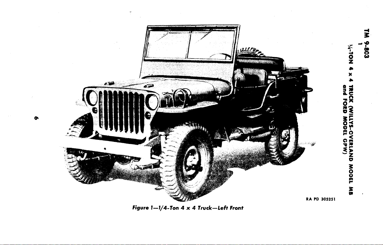
Figure I--I/4-Ton 4 x 4 Truck-Left Front
RA PD 305251
f
Page 7
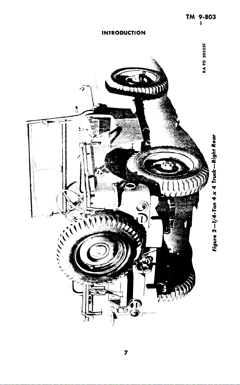
INTRODUCTION
TM 9-803
1
0,
c
0
0
Page 8

TM 9-803
1
l/,-TON 4 x 4 TRUCK (WILLYS-OVERLAND MODEL MB
and FORD MODEL GPW)
8
Page 9

INTRODUCTION
TM 9-803
1
Page 10
TM 9-803
2-3
l/i-TON 4 x 4 TRUCK (WILLYS-OVERLAND MODEL MB
and FORD MODEL GPW)
Section II
DESCRIPTION AND TABULATED DATA
Paragraph
Description .
Data _.._., .._.... .
2. DESCRIPTION.
mm._._ m,~?_ _~.,L_,_ .
a.
1 YPe*
carrier especially adaptable for reconnaisance or command, and
designated as I/d-ton 4 x 4 Truck. It is a four-wheel vehicle with
four-wheel drive. The engine is a 4-cylinder gasoline unit located in
the conventional place, under the hood at the front of the vehicle.
A conventional three-speed transmission equipped with a transfer
case provides additional speeds for traversing difficult terrain. The
body is of the open type with an open driver’s compartment. The
folding top can be removed and stowed: and. the windshield tilted
forward on top of the hood, or opened upward and outward. A spare
wheel equipped with a tire is mounted on thr rear of the body, and a
pintle hook is provided to haul trailed loads. Specifications of the
vehicle are given under “Data” (par. 3). Genrral physical character-
istics are shown in figures 1 through 4.
h. Identification. The manufacturer’s chassis serial number is
stamped on a plate inside the left frame side member at the front end,
and on the name plate (fig. 6). The engine serial number is stamped
on the right side of the cylinder block. front upper corner. The U.S.A.
registration number is painted on both sides of the hood.
~nls vemcle is a generai purpose, personnei, or cargo
2
3
3. DATA.
a. Vehicle Specifirations.
Wheelbase
Length, over-all
Width, over-all
Height, over-all-top up
-top down 52 in.
Wheel size combat 16 x 4.50 E
Tire size
Tire pressure (front and rear)
Tire type
Tire plies
Tread (center-to-center)-front
-rear
Crew, operating
Passenger capacity including crew
10
.., 62 in.
16 x 6.00 in.
mud and snow
80 in.
1321/d in.
69$/4 in.
35 lb
6
49 in.
49 in.
2
5
Page 11

TM 9-803
DESCRIPTION AND TABULATED DATA
Weights:
Road, including gas and water 2,453 lb
Gross (loaded) 3,253 lb
Shipping (less water and fuel) 2,337 lb
Boxed gross 3,062 lb
Maximum pay load 800 lb
Maximum trailed load 1,000 lb
Ground clearance 8¾ in.
Pintle height (loaded) 21 in.
Kind and grade of fuel (octane rating) Gasoline (68 mm)
Approach angle 45 deg
Departure angle 35 deg
Shipping dimensions—cubic feet 331
—square feet 57
b. Performance.
Maximum allowable speeds (mph) with transfer case in “HIGH” range:
High gear (3rd) 65
Intermediate gear (2nd) 41
Low gear (1st) 24
Reverse gear . 18
Maximum allowable speeds (mph) with transfer case in
“LOW” range:
High gear (3rd) 33
Intermediate gear (2nd) 21
Low gear (1st) 12
Reverse gear 9
Maximum grade ability 60 pct
Minimum turning radius—right 17½ ft
—left 171/2 ft
Maximum fording depth. 21 in.
Towing facilities—front none
—rear pintle hook
Maximum draw-bar pull 1,930 lb
Engine idle speed 600 rpm
Miles per gallon—(high gear—high range)
average conditions 20
Cruising range—(miles) average conditions 20
3
c. Capacities.
Engine crankcase capacity—dry 5 qt
—refill 4 qt
Transmission capacity % qt
Transfer case capacity 1 I/I qt
11
Page 12
TM 9-803
3
+TON 4 x 4 TRUCK (WILLYS-OVERLAND MODEL MB
and FORD MODEL GPW)
Front axle capacity (differential) . 1y4 qt
Rear axle capacity (differential) 1r/4 qt
Front axle steering knuckle universal joint. j/4 qt
Steering gear housing y4 qt
Air cleaner (oil bath). . s/s qt
Fuel tank capacity 15 gal
Cooling system capacity 11 qt
Brake system (hydraulic brake fluid) j/4 qt
Shock absorbers--front 5 oz
-rear .., . __.. 53/4 02
d. Communications.
(1) RADIO OUTLET Box. A radio outlet box is provided on the
later vehicles to use the vehicle battery (6-volt current supply). This
outlet is located against the body side panel at the right front seat.
(2) AUXILIARY GENERATOR. A 12-volt, 55ampere auxiliary generator is furnished on some vehicles. The generator is driven by a
V-belt from a power take-off unit on the rear of the transfer case.
Instructions for operation and care accompany those vehicles.
12
Page 13
TM 9-803
4
Section III
DRIVING CONTROLS AND OPERATION
Paragraph
Instruments and controls . . , . .
Use of instruments and controls in vehicular operation. . .
Towing the vehicle....................................... 6
A B C
4
5
WVUTSRQPON
A
STEERING WHEEL
E
HORN BUTTON
WINDSHIELD WIPERS
C
D
WINDSHIELD ADJUSTING ARMS
E
AMMETER
F
HAND BRAKE
G
WINDSHIELD CLAMPS
H
CAUTION PLATE
I
NAME PLATE
J
SHIFT PLATE
K
TRANSMISSION GEAR SHIFT LEVER
1
TRANSFER CASE SHIFT LEVER-FRONT AXLE DRIVE AC
M
TRANSFER CASE SHIFT LEVER-AUXILIARY RANGE
N
STARTING SWITCH
0
TEMPERATURE GAGE
ACCELERATOR FOOT REST
;
SPEEDOMETER
ML
R
ACCELERATOR (FOOT THROTTLE)
S
OIL PRESSURE GAGE
1
FUEL GAGE
U
BRAKE PEDAL
V
INSTRUMENT PANEL LIGHT SWITCH
W
CLUTCH PEDAL
X
FUEL TANK
Y
FIRE EXTINGUISHER
Z
SAFETY STRAP
AA
HEADLIGHT FOOT SWITCH (BEAM CONTROL)
AR
BLACKOUT LIGHT SWITCH
BLACKOUT DRIVING LIGHT SWITCH
REAR VISION MIRROR
AD
AE
CHOKE CONTROL
AF
IGNITION SWITCH
AC
HAND THROTTLE
AH
RIFLE HOLDER
K J I
RA PD 334753
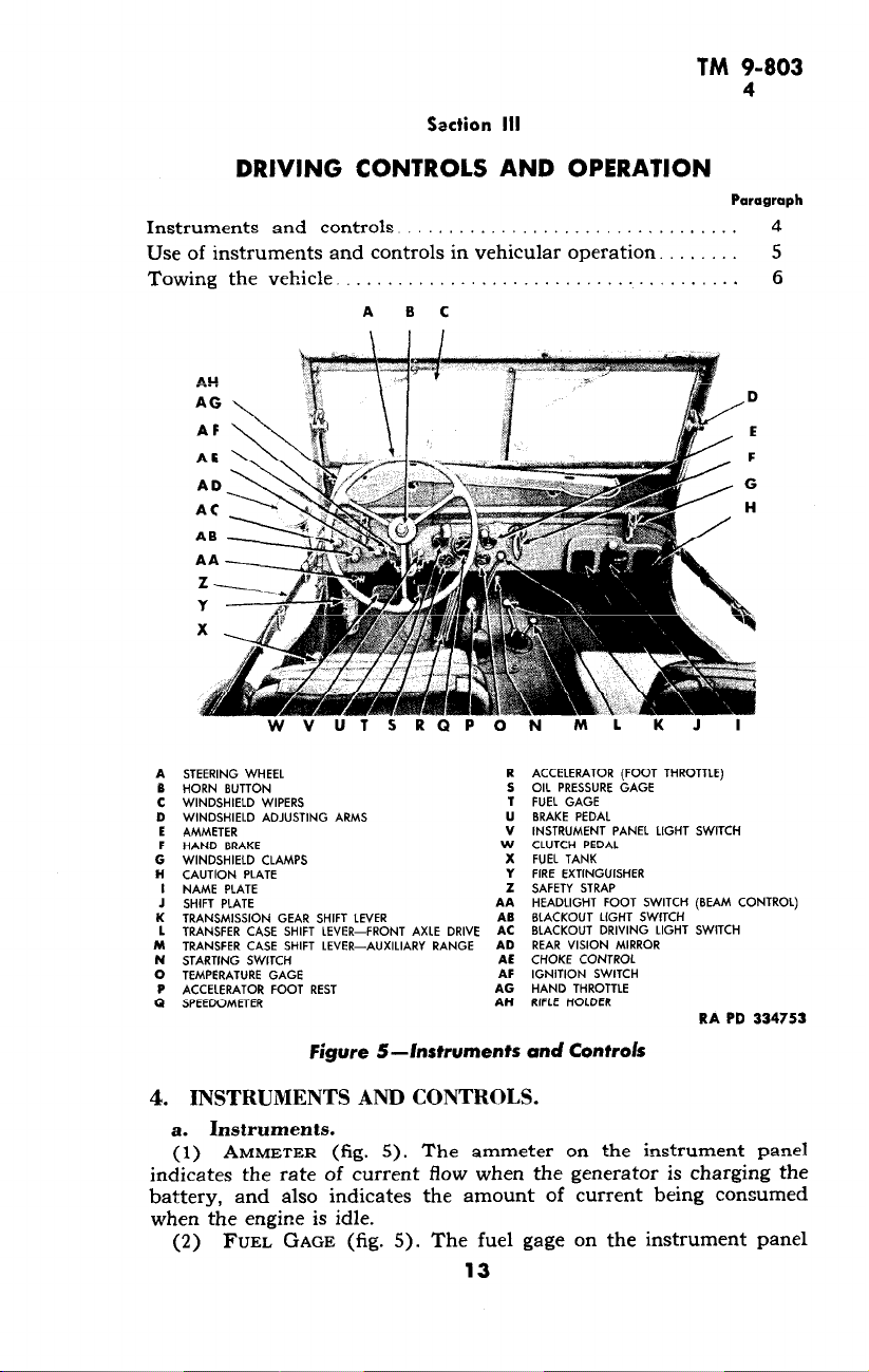
Figure 5-Instruments and Controls
INSTRUMENTS AND CONTROLS.
4.
a. Instruments.
(1) AMMETER (fig. 5). The ammeter on the instrument panel
indicates the rate of current flow when the generator is charging the
battery, and also indicates the amount of current being consumed
when the engine is idle.
(2) FUEL GAGE (fig. 5). The fuel gage on the instrument panel
13
Page 14

TM 9-803
4
‘/,-TON 4 x 4 TRUCK (WILLYS-OVERLAND MODEL MB
and FORD MODEL GPW)
Figure 6-Name Pfafe
RA PD 305162
Figure 7-Caution Plate
RA PD 330838
RA PD 305161
Figure (I-Shift Plate
14
Page 15

TM 9-803
4
DRIVING CONTROLS AND OPERATION
is an electrical unit which indicates the fuel level in the tank, and
only registers while the ignition switch is turned on.
(3) OIL PRESSURE GAGE (fig. 5). The oil pressure gage located
on the instrument panel indicates the oil pressure when the engine
is running.
(4) SPEEDOMETER (fig. 5). The speedometer on the instrument
panel indicates in miles per hour the speed at which the vehicle is
being driven. The odometer (in upper part of speedometer face)
registers the total number of miles the vehicle has been driven. A
trip indicator (in lower part of speedometer face) gives distance
covered on any trip. Set trip indicator by turning the knurled control shaft extending through back of the speedometer.
the temperature of the solution in the cooling system.
driving light switch (B.O. DRIVE) on the instrument panel controls
the blackout driving light located on the left front fender, to furnish
additional light during blackout periods. To operate light, first pull
the blackout light switch button to the first position, then pull blackout driving light switch knob. To switch off the light, push in blackout drivind light switch knob.
TEMPERATURE GAGE (fig. 5). The temperature gage registers
(5)
b. Controls.
(1) BLACKOUT DRIVING LIGHT SWITCH (fig. 5). The blackout
Fieure 9-Blackout Light Switch Operating ?ositions
(2) BLACKOUT LIGHT SWITCH (fig. 5). The knob on the instrument panel (LIGHTS) controls the entire lighting system, including
the instrument panel lights, blackout driving light, and stop lights.
A circuit-breaker type fuse, on the back of the switch, opens when
a short circuit occurs, and closes when the thermostatic element cools.
The light switch is a four-position push-pull type with a safety lock
(fig. 9). When the control knob is pulled out to the first position, the
blackout headlights and blackout stop and taillights are turned on.
15
Page 16
TM 9-803
4
I/,-TON 4 x 4 TRUCK (WILLYS-OVERLAND MODEL MB
The switch control knob travel is automatically locked in this position
by the lock-out button to prevent accidentally turning on of the
service (bright) lights in a blackout area. To obtain service lights,
push in on lock-out control button on the left side of the switch, and
pull out control knob to second position. When switch is in this position service headlights, service stop and taillights are turned on, and
the panel lights can be turned on by pulling out on the knob
(PANEL LIGHTS). CAUTION: When driving during the day, press
in lock-out control button, and pull control knob out to the last or
stop light position to cause only the regular stop light to function.
and FORD MODEL GPW)
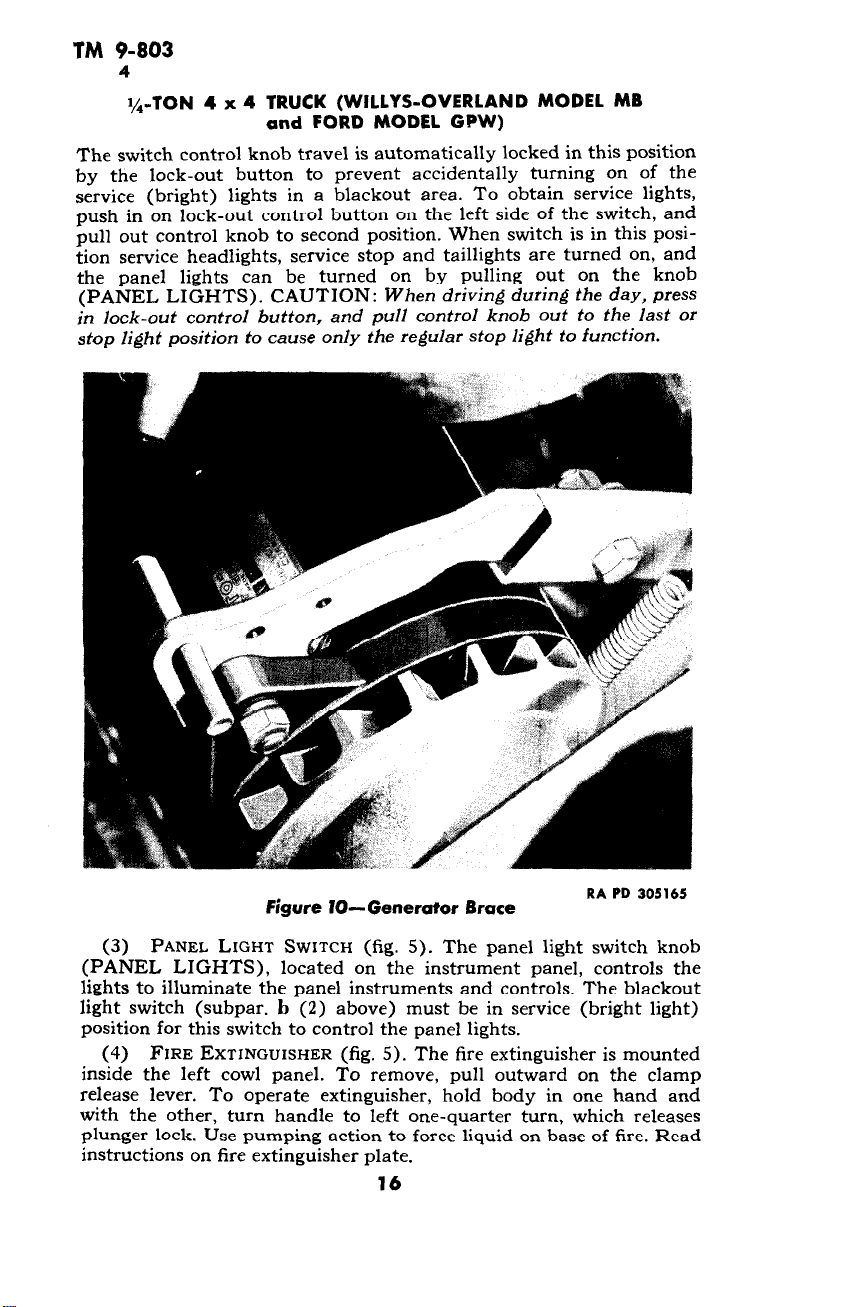
Figure IO- Generator Brace
RA PD 305165
(3) PANEL LIGHT SWITCH (fig. 5). The panel light switch knob
(PANEL LIGHTS), located on the instrument panel, controls the
lights to illuminate the panel instruments and controls. The blackout
light switch (subpar. b (2) above) must be in service (bright light)
position for this switch to control the panel lights.
(4) FIRE EXTINGUISHER (fig. 5). The fire extinguisher is mounted
inside the left cowl panel. To remove, pull outward on the clamp
release lever. To operate extinguisher, hold body in one hand and
with the other, turn handle to left one-quarter turn, which releases
plunger lock. Use pumping action to force liquid on base of fire. Read
instructions on fire extinguisher plate.
16
Page 17
TM 9-803
4-5
DRIVING CONTROLS AND OPERATION
(5)
HAND BRAKE (fig. 5). The hand brake is applied by pulling
out on the handle at the center of the instrument panel. Pull the
handle out in a vertical position when the vehicle is parked. The
brake is released by turning the handle one-quarter turn.
(6) WINDSHIELD ADJUSTING ARMS (fig. 5). The windshield
adjustment arms are mounted on each end of the windshield frame.
To open windshield, loosen knobs and push forward on lower part,
then set by tightening the knobs.
(7) WINDSHIELD CLAMPS (fig. 5). The windshield clamps are
located on the lower part of the windshield. Pull up on both clamps
and unhook them, after which the windshield can be lowered on top
of the hood. Be sure to hook down the windshield, using the hold-
down catches on both sides of the hood.
(8) GENERATOR BRACE (fig. 10). The generator brace can be
pulled up to release tension on the fan belt and stop the fan from
throwing water over the engine when crossing a stream. Pull gen-
erator out to running position as soon as possible thereafter, and it
will lock in place. CAUTION: Be sure fan belt is on pulleys.
(9)
OTHER INSTRUMENTS AND CONTROLS. Other instruments and
controls are of the conventional type, and are shown in figure 5.
5. USE OF INSTRUMENTS AND CONTROLS IN VEHICULAR
OPERATION.
a. Before-operation Service. Perform the services in paragraph
13 before attempting to start the engine.
b.
Starting Engine. To start the engine proceed as follows:
(1)
Put transmission gearshift lever in neutral position (fig. 8).
(2)
Pull out hand throttle button about 3/4 inch to 1 inch.
(3) Pull out choke button all the way. NOTE: Ch’oking is not
necessary when engine is warm.
(4)
Turn ignition to “ON” position.
(5) Depress clutch pedal to disengage clutch, and hold pedal
down while engine is started.
(6) Step on starting switch to crank again. Release switch as
soon as engine starts.
(7) Adjust choke and throttle control buttons to obtain proper
idling speed. As engine warms up, push choke button all the way in.
(8)
Check oil pressure gage reading; at idle speed the indicator
hand should show at least 10 on the gage.
(9) Check ammeter for charge reading. Check fuel gage for
indication of fuel supply.
(10)
After engine has operated a few minutes, check temperature
gage reading. Normal operating temperature is between 160°F and
185OF.
(11)
In extremely cold weather refer to paragraph 7.
c. Placing Vehicle in Motion.
(1)
For daytime driving turn on service stop light (par. 4 b (2)).
(2) Place transfer case right-hand shift lever in rear position to
soX!ri 0---48~~-2
17
Page 18
TM 9-803
5
I/,-TON 4 x 4 TRUCK (WILLYS-OVERLAND MODEL MB
and FORD MODEL GPW)
engage “HIGH” range, then place center shift lever in forward position to disengage front axle (fig. 8).
(3) Depress clutch pedal, and move transmission shift lever
toward driver and backward to engage low (1st) gear (fig. 8).
(4) Release parking (hand) brake.
(5) Slightly depress accelerator to increase engine speed, and at
the same time slowly release clutch pedal, increasing pressure on
accelerator as clutch engages and vehicle starts to move. NOTE:
During the following operations perform procedures outlined in paragraph 14.
(6) Increase speed to approximately 10 miles per hour, depress
clutch pedal, and at the same time release pressure on accelerator.
Move transmission shift lever out of low gear into neutral, and then
into second gear. No double clutching is required. Release clutch
pedal and accelerate engine.
(7) After vehicle has attained a speed of approximately 20 miles
per hour, follow the same procedure as outlined above in order to
shift into high (3rd) gear, moving the gearshift lever straight back.
d. Shifting to Lower Gears in Transmission. Shift to a lower
gear before engine begins to labor, as follows: Depress clutch pedal
quickly, shift to next lower gear, increase engine speed, release clutch
pedal slowly, and accelerate. When shifting to a lower gear at any
rate of vehicle speed, make sure that the engine speed is synchronized
with vehicle speed before clutch is engaged.
e. Shifting Gears in Transfer Case (fig. 8). The transfer case is
the means by which power is applied to the front and rear axles. In
addition, the low gear provided by the transfer case further increases
the number of speeds provided by the transmission. The selection of
gear ratios depends upon the road and load conditions. Shift gears
in the transfer case in accordance with the shift plate (fig. S), and
observe the instructions on the caution plate (fig. 7). The transmis-
sion gearshift does not in any way affect the selection or shifting of
the transfer case gears. Vehicle may be driven by rear axle, or by both
front and rear axles. The front axle cannot be driven independently.
(1) FRONT AXLE ENGAGEMENT. Front axle should be engaged
only in off-the-road operation, slippery roads, steep grades, or during
hard pulling. Disengage front axle when operating on average roads
under normal conditions.
(a) En&aging Front Axle with Transfer Case in “HIGH” Range.
With transfer case in “HIGH” range, move front axle drive shift lever
to “IN” position. Depressing the clutch pedal will facilitate shifting.
(b) Disengaging Front Axle with Transfer Case in “HIGH”
Range. Move front axle drive shift lever to “OUT” position. Depress
the clutch pedal to facilitate shifting.
(c) Disengaging Front Axle when Transfer Case is in “LOW.”
1. Depress clutch pedal, then shift transfer case lever into
“HIGH.”
2. Shift front axle drive lever into “OUT” position.
18
Page 19
TM 9-803
5-6
DRIVING CONTROLS AND OPERATION
3. Release clutch pedal and accelerate engine to desired speed.
(2) ENGAGING TRANSFER CASE LOW RANGE. Transfer case LOW
range cannot be engaged until front axle drive is engaged.
(a) Engage front axle drive (subpar. e (1) above).
(b) Depress clutch pedal and move transfer case shift lever into
“IV (neutral) position.
Ro1s.c.~~ rltrtrh nm-lal anA nrrrlr=cate ena;ne
(c)
*.bAc”“.. L.YCC.. y-‘Cuu _...A Y..LL.L.“... . . ..b...L.
(d) Depress clutch pedal again and move transfer case shift lever
forward into “LOW” position.
(e> Release clutch pedal, and accelerate engine to desired speed.
(3) ENGAGING TRANSFER CASE-“LOW” to “HIGH.” This shift
can be made regardless of vehicle speed.
(a) Depress clutch pedal and move transfer case shift lever into
“HIGH” position.
(b) Release clutch pedal, and accelerate engine to desired speed.
f: Stopping the Vehicle.
apply brakes by depressing brake pedal.
(1) When vehicle speed has been reduced to engine idle speed,
depress clutch pedal and move transmission shift lever to “N”
(neutral) position (fig. 8).
(2) When vehicle has come to a complete stop, apply parking
(hand) brake, and release clutch and brake pedals.
g. Reversing the Vehicle. To shift into reverse speed, first bring
the vehicle to a complete stop.
(1) Depress clutch pedal.
(2) Move transmission shift lever to the left and forward into
“R” (reverse) position.
(3) Release clutch pedal slowly. and accelerate as load is picked
up.
h. Stopping the Engine. To stop the engine turn the ignition
switch to “OFF” position. NOTE: Before a new or reconditioned
vehicle is first put into service: make run-in tests as outlined in section 10.
Remove foot from accelerator, and
6. TOWING THE VEHICLE.
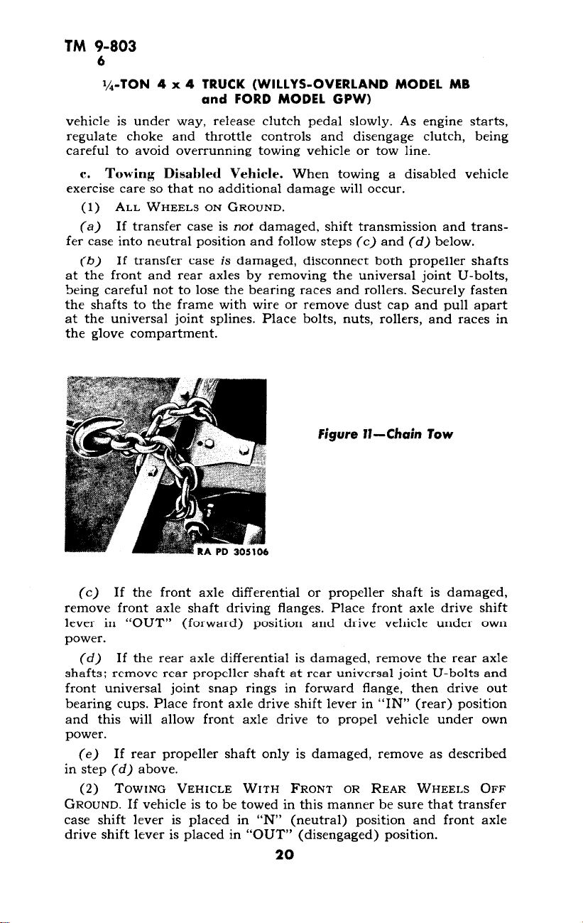
a. Attaching Tow Line. To tow vehicle attach the chain, rope or
cable to the front bumper bar at the frame side rail gusset (fig. 11).
Do not tow from the middle of the bumper. To attach tow line, loop
chain, rope, or cable over top of bumper, bring tow line up across
front of bumper, and back on opposite side of frame, then hook or tie.
h. Towing to Start Vehicle. Place transfer case (aux. RANGE)
.h;ff la.,-v nf tn....4 . ..ah.rl, en l ha ram.. I“UTr,U”\ D1ms.a f-n-+ owla
L.IIIC SL”LA “I CVWL” “LlA,C.x. L” CA.C ‘La, \ AAIU11 ,.
1 AcIbC AI”“C a.%‘&
drive shift lever in “OUT” (forward) position. Depress clutch pedal
and engage transmission in high (3rd) speed. Switch ignition “ON,”
pull out choke control knob (if engine is cold), pull out throttle knob
about 1 inch, release parking (hand) brake, and tow vehicle. After
19
Page 20
TM 9-803
6
l/,-TON 4 x 4 TRUCK (WILLYS-OVERLAND MODEL MB
and FORD MODEL GPW)
vehicle is under way, release clutch pedal slowly. As engine starts,
regulate choke and throttle controls and disengage clutch, being
careful to avoid overrunning towing vehicle or tow line.
c. Towing Disabled Vehicle. When towing a disabled vehicle
exercise care so that no additional damage will occur.
fer case into neutral position and follow steps (c) and (d) below.
at the front and rear axles by removing the universal joint U-bolts,
being careful not to lose the bearing races and rollers. Securely fasten
the shafts to the frame with wire or remove dust cap and pull apart
at the universal joint splines. Place bolts, nuts, rollers, and races in
the glove compartment.
A. I XX,rrX7?7. n _\I P_-r,rrr7r\
(1)
X7L.L. ““~l?rc.L3 “IY UK”“IY”.
(a) If transfer case is not damaged, shift transmission and trans-
(b) If transfer case is damaged, disconnect both propeller shafts
(c) If the front axle differential or propeller shaft is damaged,
remove front axle shaft driving flanges. Place front axle drive shift
lever in “OUT” (forward) position and drive vehicle under own
power.
(d) If the rear axle differential is damaged, remove the rear axle
shafts; remove rear propeller shaft at rear universal joint U-bolts and
front universal joint snap rings in forward flange, then drive out
bearing cups. Place front axle drive shift lever in “IN” (rear) position
and this will allow front axle drive to propel vehicle under own
power.
(e) If rear propeller shaft only is damaged, remove as described
in step (d) above.
(2) TOWING VEHICLE WITH FRONT OR REAR WHEELS OFF
GROUND. If vehicle is to be towed in this manner be sure that transfer
case shift lever is placed in “N” (neutral) position and front axle
drive shift lever is placed in “OUT” (disengaged) position.
20
Page 21
TM 9-803
7
Section IV
OPERATION UNDER UNUSUAL CONDITIONS
Paragraph
Operation in cold weather
Operation in hot weather
Operation in sand ,.
Operation in ianding
Decontamination
7. OPERATION IN COLD WEATHER.
a. Purpose. Operation of automotive equipment at subzero
temperatures presents problems that demand special precautions and
extra careful servicing from both operation and maintenance personnel, if poor performance and total functional failure are to be avoided.
b. Gasoline. Winter grade of gasoline is designed to reduce cold
. .._-&I___. ^L_._L:-- -1:cf-..Ic:,.-.
wcaL,lrl YLill L111g UIIIICUILICS,
should be used in cold weather operation.
c. Storage and Handing of Gasoline. Due to condensation of
moisture from the air, water will accumulate in tanks, drums, and
containers. At low temperatures, this water will form ice crystals that
will clog fuel lines and carburetor jets, unless the following precau-
tions are taken:
(1) Strain the fuel through filter paper, or any other type of
strainer that will prevent the passage of water. CAUTION: Gasoline
flowing over a surface generates static electricity that wiN result in a
spark, unless means are provided to ground the electricity. Always
provide a metallic contact between the container and the tank, to
assure an effective ground.
(2) Keep tank full, if possible. The more fuel there is in the tank,
the smaller will be the volume of air from which moisture can be
condensed.
(3) Add ‘/z pint of denatured alcohol, Grade 3, to the fuel tank
each time it is filled. This will reduce the hazard of ice formation in
the fuel.
(4) Be sure that all containers are thoroughly clean and free from
rust before storing fuel in them.
(5) If possible, after filling or moving a container, allow the fuel
to settle before filling fuel tank from it.
(6) Keep all closures of containers tight to prevent snow, ice, dirt,
and other foreign matter from entering.
(7) Wipe all snow or ice from dispensing equipment and from
around fuel tank filler cap before removing cap to refuel vehicle.
d. Lubrication.
(1) TRANSMISSION AND DIFFERENTIAL.
tbleiefoie 4.l_ . . ..-c_- --_.l- __^L^^ c..,.,
, L‘lC Wl‘lLCl g;lauc lll”L”‘ ,UCl
21
7
8
9
i0
11
Page 22
TM 9-803
7
I/,-TON 4 x 4 TRUCK (WILLYS-OVERLAND MODEL MB
and FORD MODEL GPW)
(a) Universal gear lubricant, SAE 80, where specified on figure 14,
is suitable for use at temperatures as low as -20°F. If consistent
temperature below O’F is anticipated, drain the gear cases while
warm, and refill with Grade 75 universal gear lubricant, which is suitable for operation at all temperatures below +32’F. If Grade 75
universal gear lubricant is not available, SAE 80 universal gear lubricant diluted with the fuel used by the engine, in the proportion of one
part fuel to six parts universal gear lubricant, may be used. Dilute
make-up oil in the same proportion before it is added to gear cases.
(b) After engine has been warmed up, engage clutch, and maintain engine speed at fast idle for 5 minutes, or until gears can be
engaged. Put transmission in low (first) gear, and drive vehicle for
100 yards, being careful not to stall engine. This will heat gear lubri-
cants to the point where normal operation can be expected.
(2) CHASSIS POINTS. Lubricate chassis points with general
purpose grease, No. 0.
(3) STEERING GEAR HOUSING. Drain housing, if possible, or use
suction gun to remove as much lubricant as possible. Refill with universal gear lubricant, Grade 75, or, if not available, SAE 80 universal
gear lubricant diluted with fuel used in the engine, in the proportion
of one part fuel to six parts SAE 80 universal gear lubricant. Dilute
make-up oil in the same proportion before it is added to the housing.
(4) OILCAN POINTS. For oilcan points where engine oil is pre-
scribed for above O°F, use light lubricating, preservative oil.
e. Protection of Cooling Systems.
(1) USE ANTIFREEZE COMPOUND. Protect the system with anti-
freeze compound (ethylene-glycol type) for operation below i 32’F.
The following instructions apply to use of new antifreeze compound.
(2) CLEAN COOLING SYSTEM. Before adding antifreeze compound,
clean the cooling system, and completely free it from rust. If the cool-
ing system has been cleaned recently, it may be necessary only to
drain, refill with clean water, and again drain. Otherwise the system
should be cleaned with cleaning compound.
(3) REPAIR LEAKS. Inspect all hoses, and replace if deteriorated.
Inspect all hose clamps, plugs, and pet cocks and tighten if necessary.
Repair all radiator leaks before adding antifreeze compound. Correct
all leakage of exhaust gas or air into the cooling system.
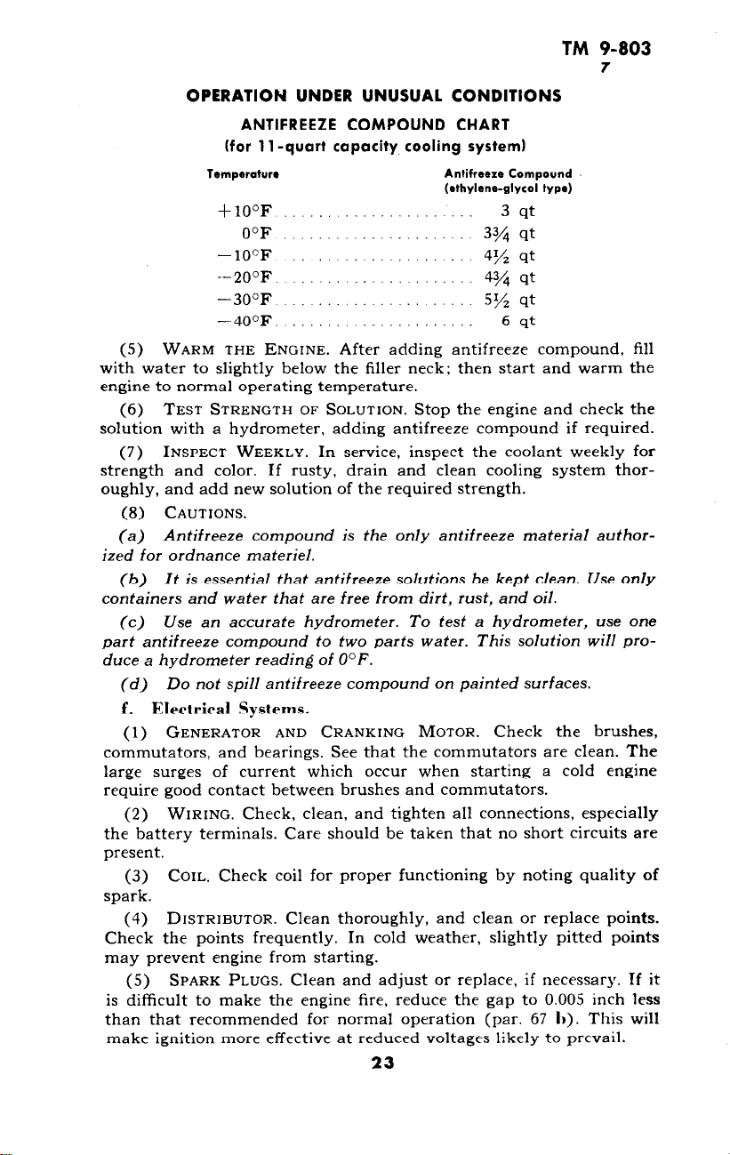
(4) ADD ANTIFREEZE COMPOUND. When the cooling system is
clean and tight, fill the system with water to about one-third capacity.
Then add antifreeze compound, using the proportion of antifreeze
compound to the cooling system capacity indicated below. Protect
the system to at least lOoF below the lowest temperature expected to
be experienced during the winter season.
22
Page 23
TM 9-803
7
OPERATION UNDER UNUSUAL CONDITIONS
ANTIFREEZE COMPOUND CHART
(for 11 -quart capacity cooling system)
Tsmperatur*
+lO°F .,.,.. ._._........_._
O°F 33/4 qt
- 10°F
--20°F 43/4 qt
-30°F ._.... _. _. 5% qt
-40°F. ._.........._
(5) WARM THE ENGINE. After adding antifreeze compound, fill
with water to slightly below the filler neck: then start and warm the
engine to normal operating temperature.
(6) TEST STRENGTH OF SOLUTION. Stop the engine and check the
solution with a hydrometer, adding antifreeze compound if required.
TwcDFrr Wurzu1”
(7)
IL..,1 x,L L . . YYLX” 1 . &&I YCI . AL._,
ln .ZPPII;FP ;nrner+ the mnlant w~~lrl,, mr
strength and color. If rusty, drain and clean cooling system thoroughly, and add new solution of the required strength.
(8) CAUTIONS.
(a) Antifreeze compound is the only antifreeze material author-
ized for ordnance materiel.
(b) It is essential that antifreeze solutions be kept clean. Use only
containers and water that are free from dirt, rust, and oil.
(c) Use an accurate hydrometer. To test a hydrometer, use one
part antifreeze compound to two parts water. This solution will produce a hydrometer reading of O°F.
(d) Do not spill antifreeze compound on painted surfaces.
f. Elettrical Systems.
(1) GENERATOR AND CRANKING MOTOR. Check the brushes,
commutators, and bearings. See that the commutators are clean. The
large surges of current which occur when starting a cold engine
require good contact between brushes and commutators.
(2) WIRING. Check, clean, and tighten all connections, especially
the battery terminals. Care should be taken that no short circuits are
present.
(3) COIL. Check coil for proper functioning by noting quality of
spark.
(4) DISTRIBUTOR. Clean thoroughly, and clean or replace points.
Check the points frequently. In cold weather, slightly pitted points
may prevent engine from starting.
(5) SPARK PLUGS. Clean and adjust or replace, if necessary. Tf it
is difficult to make the engine fire, reduce the gap to 0.005 inch less
than that recommended for normal operation (par. 67 1)). This will
make ignition more effective at reduced voltages likely to prevail.
23
Antifreeze Compound
(ethylene-glycol type)
3 qt
4% nt
‘,ri -I-
6 qt
‘a’YyLC._ L&1.. ~vvIcIssc ..LC...J
Page 24
TM 9-803
7
I/,-TON 4 x 4 TRUCK (WILLYS-OVERLAND MODEL MB
and FORD MODEL GPW)
(6) TIMING. Check carefully. Care should be taken that the spark
is not unduly advanced nor retarded.
(7) BATTERY.
(a) The efficiency of batteries decreases sharply with decreasing
temperatures, and becomes practically nil at -4O’F. Do not try to
start the engine with the battery when it has been chilled to temperatures below -30°F until battery has been heated, unless a warm
slave battery is available. See that the battery is always fully
charged, with the hydrometer reading between 1.275 and 1.300. A
fully charged battery will not freeze at temperatures likely to be
encountered even in arctic climates, but a fully discharged battery
will freeze and rupture at +5’F.
(b) Do not add water to a battery when it has been exposed to
subzero temperatures unless the battery is to be charged immediately.
If water is added and the battery not put on charge, the layer of water
will stay at the top and freeze before it has a chance to mix with
the acid.
(8) LIGHTS. Inspect the lights carefully. Check for short circuits
and presence of moisture around sockets.
(9) ICE. Before every start, see that the spark plugs, wiring, or
other electrical equipment is free from ice.
g. Starting and Operating Engine.
(1) INSPECT CRANKING MOTOR MECHANISM. Be sure that no
heavy grease or dirt has been left on the cranking motor throwout
mechanism. Heavy grease or dirt is liable to keep the gears from being
meshed, or cause them to remain in mesh after the engine starts running. The latter will ruin the cranking motor and necessitate repairs.
(2) USE OF CHOKE. A full choke is necessary to secure the rich
air-fuel mixture required for cold weather starting. Check the butter-
fly valve to see that it closes all the way, and otherwise functions
properly.
(3) CARBURETOR AND FUEL PUMP. The carburetor, which will
give no appreciable trouble at normal temperatures, is liable not to
operate satisfactorily at low temperatures. Be sure the fuel pump has
no leaky valves or diaphragm, as this will prevent the fuel pump from
delivering the amount of fuel required to start the engine at low
temperatures, when turning speeds are reduced to 30 to 60 revolutions per minute.
(4) AIR CLEANERS. At temperatures below O°F do not use oil in
air cleaners. The oil will congeal and prevent the easy flow of air.
Wash screens in dry-cleaning solvent, dry, and replace. Ice and frost
formations on the air cleaner screens can cause an abnormally high
intake vacuum in the carburetor air horn hose, resulting in collapse.
(5) FUEL SYSTEM. Remove and clean sediment bulb, strainers,
etc., daily. Also drain fuel tank sump daily to remove water and dirt.
24
Page 25
OPERATION UNDER UNUSUAL CONDITIONS
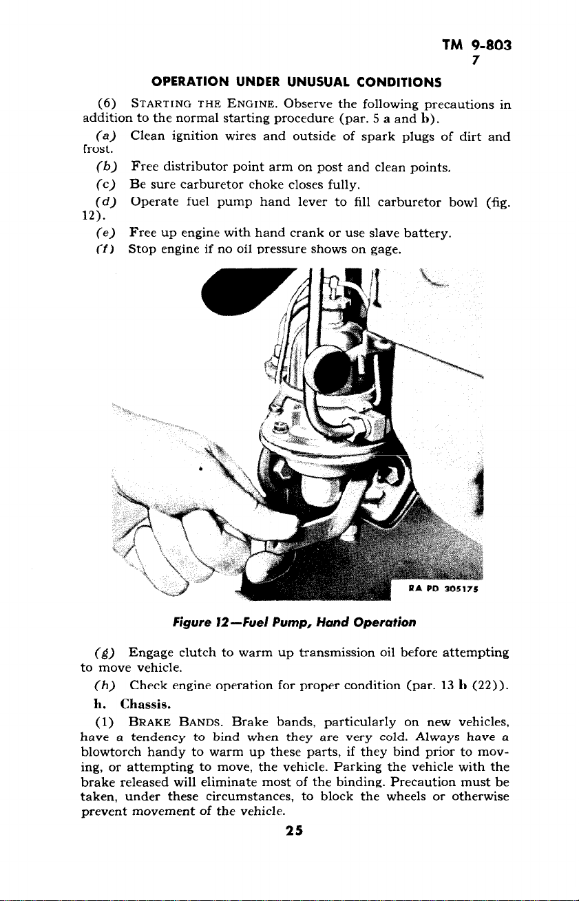
(6)
STARTING THE ENGINE. Observe the following precautions in
addition to the normal starting procedure (par. 5 a and b).
Clean ignition wires and outside of spark plugs of dirt and
(4
frost.
Free distributor point arm on post and clean points.
(h)
Be sure carburetor choke closes fully.
(c)
Operate fuel pump hand lever to fill carburetor bowl (fig.
(d)
12).
Free up engine with hand crank or use slave battery.
(e)
Stop engine if no oil pressure shows on gage.
ffl
TM 9-803
7
Figure I2-Fuel Pump, Hand Operation
(g)
Engage clutch to warm up transmission oil before attempting
to move vehicle.
(h)
Check engine operation for proper condition (par. 13 b (22)).
h. Chassis.
(1) BRAKE BANDS. Brake bands, particularly on new vehicles,
have a tendency to bind when they are very cold. Always have a
blowtorch handy to warm up these parts, if they bind prior to moving, or attempting to move, the vehicle. Parking the vehicle with the
brake released will eliminate most of the binding. Precaution must be
taken, under these circumstances, to block the wheels or otherwise
prevent movement of the vehicle.
25
Page 26

TM 9-803
7-9
l/,-TON 4 x 4 TRUCK (WILLYS-OVERLAND MODEL MB
and FORD MODEL GPW)
(2) EFFECT OF Low TEMPERATURES ON METALS. Inspect the
vehicle frequently. Shock resistance of metals, or resistance against
breaking, is greatly reduced at extremely low temperatures. Operation
of vehicles on hard, frozen ground causes strain and jolting which will
result in screws breaking, or nuts jarring loose.
(3) SPEEDOMETER CABLE. Disconnect the oil-lubricated speed-
ometer cable at the drive end when operating the vehicle at tempera-
tures of -30°F and below. The cable will often fail to work properly
at these temperatures, and sometimes will break, due to the excessive
drag caused by the high viscosity of the oil with which it is lubricated.
8. OPERATION IN HOT WEATHER.
a. Protection of Vehicle. In extremely hot weather avoid the
continuous use of low gear ratios whenever possible. Check and
replenish oil and water frequently. If a flooded condition of the
engine is experienced in starting, pull the throttle control out, push
choke control in, and use the cranking motor. When engine starts,
adjust throttle control.
(1) COOLING SYSTEM. Rust formation occurs more rapidly dur-
ing.high temperatures; therefore, add rust preventive solution to the
cooling system, or clean and flush the system at frequent intervals.
(2) LUBRICATION. Lubricate the vehicle for hot weather operation
(par. 8).
(3) ELECTRICAL SYSTEM. Check the battery solution level frequently during hot weather operation, and add water as required to
keep it above the top of the plates. If hard starting is experienced in
hot, damp weather or quick changes in temperature, dry the spark
plugs, wires, and both inside and outside of distributor cap.
9. OPERATION IN SAND.
a. Operation. Reduce tire pressures in desert terrain if character
of sand demands this precaution. When operating in sand deep
enough to cause the use of a lower gear, do not exceed the speed
specified on the caution plate for the particular gear ratio (fig. 7).
b. Starting the Vehicle. When starting the vehicle in sand,
gravel, or soft terrain, engage the front wheel drive (par. 5 e (1)).
Release clutch pedal slowly so the wheels will not spin and “dig in,”
necessitating a tow or “winch-out.”
c. Clutch. Do not attempt to “jump” or “rock” the vehicle out
with a quick engagement of the clutch, particularly if a tow or winch
is available. Racing the engine usually causes the wheels to “dig in”
farther.
d. Air Cleaner. In sandy territory clean the carburetor air cleaner
more often. The frequency of cleaning depends upon the severity of
the sandy condition.
26
Page 27
TM 9-803
9-11
OPERATION UNDER UNUSUAL CONDITIONS
e.
Radiator. In desert operation check the radiator coolant supply
frequently, and see that the air passages of the core do not become
clogged.
f. For additional information on technique of operating the
vehicle in sand, refer to FM 31-25.
10. OPERATION IN LANDING.
a. Inspection. As soon as possible after completing a landing or
operation in water, inspect the vehicle for water in the various units.
(1) ENGINE. Drain the engine crankcase oil. If water or sludge
is found, flush the engine, using a mixture of half engine oil SAE 10
and half kerosene. Before putting in new oil, clean the valve chamber,
drain and clean the oil filter, and install a new filter element.
(2) FUEL SYSTEM. Inspect the carburetor bowl, fuel strainers,
fuel pump, filter, fuel tank, and lines. Clean the air cleaner and
change the oil.
(3) POWER TRAIN. Inspect the front and rear axle housings,
wheel bearings, transmission, and transfer case lubricant for presence
of sludge. If sludge is found, renew the lubricant after cleaning the
units with a mixture of half engine oil SAE 10 and half kerosene.
Lubricate the propeller shaft universal joints and spring shackles to
force out any water which might damage parts.
11. DECONTAMINATION.
a. Protection. For protective measures against chemical attacks
and decontamination refer to FM 17-59.
27
Page 28
TM 9-803
12
‘/,-TON 4 x 4 TRUCK (WILLYS-OVERLAND MODEL MB
and FORD MODEL GPW)
Section V
FIRST ECHELON PREVENTIVE MAINTENANCE SERVICE
Paragraph
Purpose ................................................ 12
Before-operation service ..................................
During-operation service ............................... 14
At-halt service ........................................ 15
After-operation and weekly service ........................ 16
12. PURPOSE.
a. To ensure mechanical efficiency it is necessary that the vehicle
be systematically inspected at intervals each day it is operated, also
weekly, so that defects may be discovered and corrected before they
result in serious damage or failure. Certain scheduled maintenance
services will be performed at these designated intervals. The services
set forth in this section are those performed by driver or crew before
operation, during operation, at halt, and after operation and weekly.
b. Driver preventive maintenance services are listed on the back
“Driver’s Trip Ticket and Preventive Maintenance Service
of
Record,” W.D. Form No. 48, to cover vehicles of all types and models.
Items peculiar to specific vehicles, but not listed on W.D. Form No.
48, are covered in manual procedures under the items to which they
are related. Certain items listed on the form that do not pertain to
the vehicle involved are eliminated from the procedures as written
into the manual. Every organization must thoroughly school each
driver in performing the maintenance procedures set forth in manuals,
whether they are listed specifically on W.D. Form No. 48 or not.
c. The items listed on W.D. Form No. 48 that apply to this
vehicle are expanded in this manual to provide specific procedures
for accomplishment of the inspections and services. These services
rr +r\
fnAl;tatn ;e.nnort;r\.. c.nA P.T~~P.-..P the t;mo nf the
are arrange-
C” IEIs,LA‘L~CL ,lK?p~L._L”rr alIll ..“1*.TLl SL LllC CllllC “1 L&I..
driver, and are not necessarily in the same numerical order as shown
on W.D. Form No. 48. The item numbers, however, are identical with
those shown on that form.
d. The general inspection of each item applies also to any sup-
porting member or connection, and generally includes a check to see
whether the item is in good condition, correctly assembled, secure,
or excessively worn.
(1) The inspection for “good condition” is usually an external
visual inspection to determine whether the unit is damaged beyond
safe or serviceable limits. The term “good condition” is explained
further by the following: not bent or twisted, not chafed or burned,
not broken or cracked, not bare or frayed, not dented or collapsed,
not torn or cut.
28
i3
Page 29
TM 9-803
12-13
FIRST ECHELON PREVENTIVE MAINTENANCE SERVICE
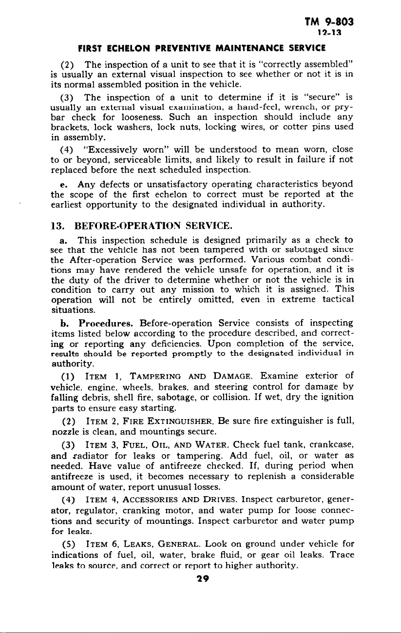
(2) The inspection of a unit to see that it is “correctly assembled”
is usually an external visual inspection to see whether or not it is in
its normal assembled position in the vehicle.
(3) The inspection of a unit to determine if it is “secure” is
usually an external visual examination, a hand-feel, wrench, or prybar check for looseness. Such an inspection should include any
brackets, lock washers, lock nuts, locking wires, or cotter pins used
in assembly.
“Excessively worn” will be understood to mean worn, close
(4)
to or beyond, serviceable limits, and likely to result in failure if not
replaced before the next scheduled inspection.
e. Any defects or unsatisfactory operating characteristics beyond
the scope of the first echelon to correct must be reported at the
earliest opportunity to the designated individual in authority.
13. BEFORE-OPERATION SERVICE.
a. This inspection schedule is designed primarily as a check to
see that the vehicle has not been tampered with or sabotaged since
the After-operation Service was performed. Various combat conditions may have rendered the vehicle unsafe for operation, and it is
the duty of the driver to determine whether or not the vehicle is in
condition to carry out any mission to which it is assigned. This
operation will not be entirely omitted, even in extreme tactical
situations.
b. Procedures. Before-operation Service consists of inspecting
items listed below according to the procedure described, and correcting or reporting any deficiencies. Upon completion of the service,
results should be reported promptly to the designated individual in
authority.
(1) ITEM 1, TAMPERING AND DAMAGE. Examine exterior of
vehicle, engine, wheels, brakes, and steering control for damage by
falling debris, shell fire, sabotage, or collision. If wet, dry the ignition
parts to ensure easy starting.
(2) ITEM 2, FIRE EXTINGUISHER. Be sure fire extinguisher is full,
nozzle is clean, and mountings secure.
(3) ITEM 3, FUEL, OIL, AND WATER. Check fuel tank, crankcase,
and radiator for leaks or tampering. Add fuel, oil, or water as
needed. Have value of antifreeze checked. If, during period when
antifreeze is used, it becomes necessary to replenish a considerable
amount of water, report unusual losses.
(4) ITEM 4, ACCESSORIES AND DRIVES. Inspect carburetor, generator, regulator, cranking motor, and water pump for loose connections and security of mountings. Inspect carburetor and water pump
for leaks.
(5) ITEM 6, LEAKS, GENERAL. Look on ground under vehicle for
indications of fuel, oil, water, brake fluid, or gear oil leaks. Trace
leaks to source, and correct or report to higher authority.
29
Page 30
TM 9-803
13
r/,-TON 4 x 4 TRUCK (WILLYS-OVERLAND MODEL MB
and FORD MODEL GPW)
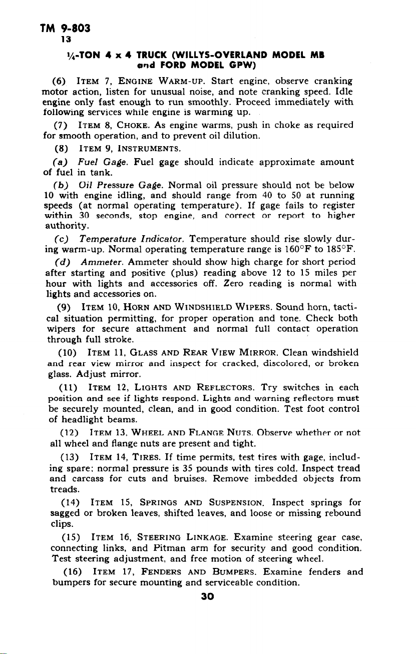
(6) ITEM 7, ENGINE WARM-UP. Start engine, observe cranking
motor action, listen for unusual noise, and note cranking speed. Idle
engine only fast enough to run smoothly. Proceed immediately with
following services while engine is warming up.
(7) ITEM 8, CHOKE. As engine warms, push in choke as required
for smooth operation, and to prevent oil dilution.
(8) ITEM 9, INSTRUMENTS.
(a) Fuel Gage. Fuel gage should indicate approximate amount
of fuel in tank.
(6) Oil Pressure Gage. Normal oil pressure should not be below
10 with engine idling, and should range from 40 to 50 at running
speeds (at normal operating temperature). If gage fails to register
within 30 seconds, stop engine,
authority.
(c) Temperature Indicator. Temperature should rise slowly dur-
ing warm-up. Normal operating temperature range is 160°F to 185’F.
(d) Ammeter. Ammeter should show high charge for short period
after starting and positive (plus) reading above 12 to 15 miles per
hour with lights and accessories off. Zero reading is normal with
lights and accessories on.
(9) ITEM 10, HORN AND WINDSHIELD WIPERS. Sound horn, tactical situation permitting, for proper operation and tone. Check both
wipers for secure attachment and normal full contact operation
through full stroke.
(10) ITEM 11, GLASS AND REAR VIEW MIRROR. Clean windshield
and rear view mirror and inspect for cracked, discolored, or broken
glass. Adjust mirror.
(11) ITEM 12, LIGHTS AND REFLECTORS. Try switches in each
position and see if lights respond. Lights and warning reflectors must
be securely mounted, clean, and in good condition. Test foot control
of headlight beams.
(12) ITEM 13, WHEEL AND FLANGE NUTS. Observe whether or not
all wheel and flange nuts are present and tight.
(13) ITEM 14, TIRES. If time permits, test tires with gage, including spare; normal pressure is 35 pounds with tires cold. Inspect tread
and carcass for cuts and bruises. Remove imbedded objects from
treads.
(14) ITEM 15, SPRINGS AND SUSPENSION. Inspect springs for
sagged or broken leaves, shifted leaves, and loose or missing rebound
clips.
(15) ITEM 16, STEERING LINKAGE. Examine steering gear case,
connecting links, and Pitman arm for security and good condition.
Test steering adjustment, and free motion of steering wheel.
(16) ITEM 17, FENDERS AND BUMPERS, Examine fenders and
bumpers for secure mounting and serviceable condition.
and correct or report to higher
30
Page 31

TM 9-803
13-14
FIRST ECHELON PREVENTIVE MAINTENANCE SERVICE
(17) ITEM 18, TOWING CONNECTIONS. Examine pintle hook for
secure mounting and serviceable condition. Be sure pintle latches
properly and locks securely.
(18) ITEM 19, BODY AND LOAD. Examine body and load (if any)
for damage. Be sure there is a cap on front drain hole under fuel
tank. See that rear drain hole cap is available in glove compartment.
CAUTION: Rear drain hole cap should be installed when about to
pass through deep water.
(19) ITEM 20, DECONTAMINATOR. Examine decontaminator for
full charge and secure mountings.
(20) ITEM 21, TOOLS AND EQUIPMENT. See that tools and equip-
ment are all present, properly stowed, and serviceable.
(21) ITEM 23, DRIVER’S PERMIT AND FORM 26. Driver must have
his operator’s permit on his person. See that vehicle manuals, Lubrication Guide, Form No. 26 (accident report) and W.D. AGO Form
No. 478 (MWO and Major Unit Assembly Replacement Record) are
present, legible, and properly stowed.
(22) ITEM 22, ENGINE OPERATION. Accelerate engine and observe
for unusual noises indicating compression or exhaust leaks; worn,
damaged, loose, and inadequately lubricated parts or misfiring.
(23) ITEM 25, DURING-OPERATION SERVICE. Begin the During-
operation Service immediately after the vehicle is put in motion.
a. While vehicle is in motion, listen for any sounds such as rattles,
knocks, squeals, or hums that may indicate trouble. Look for indications of trouble in cooling system, and smoke from any part of the
vehicle. Be on the alert to detect any odor of overheated components
or units such as generator, brakes, or clutch; check for fuel vapor
from a leak in fuel system, exhaust gas, or other signs of trouble.
Any time the brakes are used, gears shifted, or vehicle turned, consider this a test and notice any unsatisfactory or unusual performance. Watch the instruments frequently. Notice promptly any un-
usual instrument indication that may signify possible trouble in
system to which the instrument applies.
b. Procedures. During-operation Service consists of observing
items listed below according to the procedures following each item,
and investigating any indications of serious trouble. Notice minor
deficiencies to be corrected or reported at earliest opportunity, usually
at next scheduled halt.
(1) ITEM 27, FOOT AND HAND BRAKES. Foot brakes must stop
vehicle smoothly without side pull and within reasonable distance.
There should be at least 5!< reserve brake pedal travel and %-inch
free travel. Hand brake must securely hold vehicle on reasonable
incline with r${ reserve ratchet travel. There must be %-inch clearance (on cable) between relay crank and lower end of hand brake
conduit.
31
Page 32

TM 9-803
14-15
l/,-TON 4 x 4 TRUCK (WILLYS-OVERLAND MODEL MB
and FORD MODEL GPW)
(2) ITEM 28, CLUTCH. Clutch must operate smoothly without
chatter, grabbing, or slipping. Free clutch pedal travel of threequarter inch is normal.
(3) ITEM 29, TRANSMISSION. Gearshift mechanism must operate
smoothly, and not creep out of mesh.
(4) ITEM 29, TRANSFER CASE. Gearshift mechanism must operate
smoothly and not creep out of mesh.
(5) ITEM 31, ENGINE AND CONTROLS. Observe whether or not
engine responds to controls, and has maximum pulling power without
unusual noises, stalling, misfiring, overheating or unusual exhaust
smoke. If radio noise is reported during operation of the vehicle, the
driver will cooperate with the radio operator in locating the inter-
ference. See paragraph 178.
(6) ITEM 32, INSTRUMENTS. During operation observe the readings of all instruments frequently to see if they are indicating
properly.
(a) Fuel Gage. Fuel gage must register approximate amount of
fuel in tank.
(b) Oil Pressure Gage. Oil pressure gage should register 10 with
engine running idle, and 40 to 50 at operating speeds.
(c) Temperature Indicator. Temperature indicator should show
a temperature of 160°F to 18S°F after warm-up under normal conditions.
(d) Speedometer. Speedometer should show speed of vehicle
without noise or fluctuation of indicator needle. Odometer should
register accumulating trip and total mileage.
(e) Ammeter. Ammeter should show zero reading with lights on,
zero or positive (plus) charge with lights off, and slightly higher
positive (plus) charge for short time immediately after starting.
(7) ITEM 33, STEERING GEAR. Observe steering for excessive pull-
ing of vehicle to either side, wandering, or shimmy.
(8) ITEM 34, CHASSIS. Listen for unusual noises from wheel or
axles.
(9) ITEM 35, BODY. Observe body for sagging springs, loose or
torn top or windshield cover, if in use.
15. AT-HALT SERVICE.
a. At-halt Service may be regarded as the minimum mainte-
nance procedure, and should be performed under all tactical conditions, even though more extensive maintenance services must be
slighted or omitted altogether.
b. Procedures. At-halt Service consists of investigating any
deficiencies noted during operation,
according to the procedures following the items, and correcting any
deficiencies found. Deficiencies not corrected should be reported
promptly to the designated individual in authority.
inspecting items listed below
32
Page 33

TM 9-803
15
FIRST ECHELON PREVENTIVE MAINTENANCE SERVICE
(1) ITEM 38, FUEL, OIL AND WATER. Check fuel supply, oil, and
coolant; add, as required, for complete operation of vehicle to the
next refueling point. If, during period when antifreeze is used, an
abnormal amount of water is required to refill radiator, have coolant
tested with hydrometer, and add antifreeze if required.
(2) ITEM 39, TEMPERATURES. Feel each brake drum and wheel
hub, transmission, transfer case, and front and rear axles for over-
heating. Examine gear cases for excessive oil leaks.
(3) ITEM 40, AXLE AND TRANSFER CASE VENTS. Observe whether
axle and transfer case vents are present, and see that they are not
damaged or clogged.
(4) ITEM 41, PROPELLER SHAFT. Inspect propeller shaft for loose-
ness, damage, or oil leaks.
(5) ITEM 42, SPRINGS. Look for broken spring leaves or loose
clips and U-bolts.
(6) ITEM 43, STEERING LINKAGE. Examine steering control
mechanism and iinkage for damage or iooseness. investigate any
irregularities noted during operation.
(7) ITEM 44, WHEEL AND FLANGE NUTS. Observe whether or not
all wheel and axle flange nuts are present and tight.
(8) ITEM 45, TIRES. Inspect tires, including spare, for flats or
damage, and for cuts or foreign material imbedded in tread.
(9) ITEM 46, LEAKS, GENERAL. Check around engine and on
ground beneath the vehicle for excessive leaks. Trace to source, and
correct cause or report to higher authority.
(10) ITEM 47, ACCESSORIES AND BELTS. See that fan, water pump
and generator are securely mounted, that fan belt is adjusted to
l-inch deflection, and is not badly frayed. If radio noise during
operation of the engine was observed, examine all radio noise suppression capacitors, at coil, ignition and starting switches, generator,
regulator, and radio terminal box;
distributor, and all bond straps for damage, and loose mountings or
connections.
(11) ITEM 48, AIR CLEANER. If dusty or sandy conditions have
been encountered, examine oil sump for excessive dirt. Service if
required. CAUTION: Do not apply oil to element after cleaning.
(12) ITEM 49, FENDERS AND BUMPERS. Inspect fenders and
bumpers for looseness or damage.
(13) ITEM 50, TOWING CONNECTIONS. Inspect pintle hook and
trailer light socket for serviceability.
(14) ITEM 51, BODY LOAD AND TARPAULIN. Inspect vehicle and
trailed vehicle loads for shifting; see that tarpaulins are properly
secured and not damaged.
(15) ITEM 52, APPEARANCE AND GLASS. Clean windshield, mirror,
light lenses, and inspect vehicle for damage.
802011 O-48--3
suppressors at spark plugs and
33
Page 34

TM 9-803
16
l/,-TON 4 x 4 TRUCK (WILLYS-OVERLAND MODEL MB
and FORD MODEL GPW)
16. AFTER-OPERATION AND WEEKLY SERVICE.
a. After-operation Service is particularly important because at
this time the driver inspects his vehicle to detect any deficiencies that
may have developed, and corrects those he is permitted to handle.
He should report promptly, to the designated individual in authority,
the results of his inspection. If this schedule is performed thoroughly,
the vehicle should be ready to roll again on short notice. The Beforeoperation Service, with a few exceptions, is then necessary only to
ascertain whether the vehicle is in the same condition in which it was
left upon completion of the After-operation Service. The Afteroperation Service should never be entirely omitted, even in extreme
tactical situations, but may be reduced, if necessary, to the bare
fundamental services outlined for the At-halt Service.
b. Procedures. When performing the After-operation Service the
driver must remember and consider any irregularities noticed during
the day in the Before-operation, During-operation, and At-halt Serv-
ices. The After-operation Service consists of inspecting and servicing
the following items. Those items of the After-operation Service that
are marked by an asterisk (*) require additional Weekly Service, the
procedures for which are indicated in step (b) of each applicable
item,
(1) ITEM 54, FUEL, OIL, AND WATER. Check coolant and oil
levels, and add as needed. Fill fuel tank. Refill spare cans. During
period when antifreeze is used, have hydrometer test made of coolant
if loss from boiling or other cause has been considerable. Add antifreeze with water if required.
(2) ITEM 55, ENGINE OPERATION. Listen for miss, backfire, noise,
or vibration that might indicate worn parts, loose mountings, faulty
fuel mixture, or faulty ignition.
(3) ITEM 56, INSTRUMENTS. Inspect all instruments to see that
they are securely connected, and not damaged.
(4) ITEM 57, HORN AND WINDSHIELD WIPERS. Test horn for
sound, if tactical situation permits. See that horn is securely mounted
and properly connected. Operate both windshield wipers. See that
blades contact the glass effectively throughout full stroke.
(5) ITEM 58, GLASS AND REAR VIEW MIRROR. Clean glass of
windshield and rear view mirror. Examine for secure mounting and
damage.
(6) ITEM 59, LIGHTS AND REFLECTORS. Observe whether or not
lights operate properly with the switch in “ON” positions, and go out
when switch is off. See that stop light operates properly. Clean lenses
and warning reflectors.
(7) ITEM 60, FIRE EXTINGUISHER. Be sure fire extinguisher is
full, nozzle is clean, and that extinguisher is mounted securely.
(8) ITEM 61, DECONTAMINATOR. Examine decontaminator for
good condition and secure mounting.
34
Page 35

TM 9-803
16
FIRST ECHELON PREVENTIVE MAINTENANCE SERVICE
(9) ITEM 62, *BATTERY.
(a) See that battery is clean, securely mounted, and not leaking.
Inspect electrolyte level, which should be ‘/z inch above plates with
caps in place and vents open. Clean cables as required.
(b) Weekly. Clean top of battery. Remove battery caps, and add
water to r/z inch above plates. (Use distilled water if available; if not
use clean, drinkable water.) CAUTION: Do not overfill. Clean posts
and terminals if corroded, and apply light coat of grease. Tighten
terminals as needed. Tighten hold-down assembly. Clean battery
carrier if corroded.
(10) ITEM 63, *ACCESSORIES AND BELTS.
(a) Test fan belt for deflection of 1 inch. Examine belt for good
condition; it must not be frayed. Timing hole cover must be closed
and tightened.
(b) Weekly. Tighten all accessories such as carburetor, gener-
ator, regulator, cranking motor, fan, water pump, and hose connections; examine fan belt for fraying, wear, cracking, or presence of oil.
(11) ITEM 64, *ELECTRICAL WIRING.
(a) See that all ignition wiring and accessible low voltage wiring
is in good condition, clean, correctly and securely assembled and
mounted.
(b) Weekly. Tighten all loose wiring connections or electrical
unit mountings. Pay particular attention to radio noise suppression
units such as: capacitors, bond straps, and spark plug and distributor
suppressors.
(12) ITEM 65, *AIR CLEANER.
(a) Examine oil in air cleaner oil cup to see that it is at proper
level, and not excessively dirty. Clean element and refill oil cup as
required. CAUTION: Do not apply oil to element after cleaning.
(b) Weekly. Remove, clean, and dry air cleaner element and oil
cup. Fill cup to indicated oil level (approximately 5/s qt). Do not
apply oil to element after cleaning.
(13) ITEM 66, *FUEL FILTERS.
(a) Examine fuel filter for leaks.
(b) Weekly. Remove plug from bottom of dash-mounted fuel
filter. Allow water and sediment to drain out. Be sure plug is replaced
tightly, and does not leak.
(14) ITEM 67, ENGINE CONTROLS. Examine engine controls for
wear or disconnected linkage.
(15) ITEM 68, *TIRES.
(a) Inspect tires for cuts or abnormal tread wear; remove foreign
bodies from tread; inflate to 35 pounds when tires are cold.
(b) Weekly. Replace badly worn or otherwise unserviceable tires.
(16) ITEM 69, *SPRINGS.
(a) Examine springs for sag, broken or shifted leaves, loose or
missing rebound clips, or shackles.
(b) Weekly. Aline springs, and tighten U-bolts and shackles as
required.
*
35
Page 36

TM 9-803
16
l/,-TON 4 x 4 TRUCK (WILLYS-OVERLAND MODEL MB
and FORD MODEL GPW)
(17) ITEM 70, STEERING LINKAGE. Examine steering wheel
column, gear case, Pitman arm, drag link, tie rod, and steering arm
to see if they are bent, loose, or inadequately lubricated.
(18) ITEM 71, PROPELLER SHAFT. Inspect propeller shaft and
universal joints for loose connections, lubrication leaks, or damage.
(19)
ITEM 72, *AXLE AND TRANSFER VENTS.
(a) See that axle and transfer case vents are in good condition,
clean, and secure.
(b)
Weekly. Remove, clean, and replace vents.
(20) ITEM 73, LEAKS, GENERAL. Check under hood and beneath
the vehicle for indications of fuel, oil, water, or brake fluid leaks.
(21)
ITEM 74, GEAR OIL LEVELS. After units have cooled, inspect
differential transmission and transfer unit lubricant levels. Lubricant
should be level with bottom of filler hole. Observe gear cases for
leaks.
(22) ITEM 76, FENDERS AND BUMPERS. Fenders and bumpers
must be in good condition and secure.
(23) ITEM 77, *TOWING CONNECTIONS.
(a) Inspect pintle hook and towed-load connections for looseness
or damage.
(b) Weekly. Tighten pintle hook mounting bolts, and lubricate
pintle hook as required.
(24) ITEM 78, BODY AND TARPAULINS. Inspect body, top, and
windshield cover for damage and proper stowage. Make sure rear
drain below fuel tank is open, and that cap is in glove compartment.
(25) ITEM 82, *TIGHTEN.
(a) Tighten any loose wheel, axle drive flange, and spring U-bolt
nuts.
(b) Weekly. Tighten all vehicle assembly or mounting nuts or
screws that inspection indicates require tightening.
(26)
ITEM 83, *LUBRICATE AS NEEDED.
(a) Lubricate spring shackles and steering linkage, if lubrication
is needed.
(b)
cation Guide as requiring weekly attention, also points that experience and operating conditions indicate need lubrication. Observe
latest lubrication directives.
fuel tank cleaned of dirt and water. Remove excessive dirt or grease
from exterior of the engine.
thoroughly; clean engine.
and equipment assigned to vehicle are present and secure.
Weekly. Lubricate points indicated on current vehicle Lubri-
(27)
ITEM 84, *CLEAN ENGINE AND VEHICLE.
(a) Clean dirt and trash from inside of body. Keep sump under
(b) Weekly. Wash vehicle if possible. If not possible, wipe off
(28)
ITEM 85, TOOLS AND EQUIPMENT. Check to see that all tools
36
Page 37

TM 9-803
17-18
Section VI
LUBRICATION
Paragraph
Lubrication Guide 17
Detailed lubrication instructions 18
17. LUBRICATION GUIDE.
a. War Department Lubrication Guide No. 501 (figs. 13 and 14)
prescribes lubrication maintenance for the ye-ton 4 x 4 truck.
b. A Lubrication Guide is placed on or is issued with each vehicle
and is to be carried with it at all times. In the event the vehicle is
received without a Guide, the using arm shall immediately requisition a replacement from the Commanding Officer, Fort Wayne Ordnance Depot, Detroit 32, Mich.
c. Lubrication instructions on the Guide are binding on all
echelons of maintenance and there shall be no deviations from these
instructions.
d. Service intervals specified on the Guide are for normal operation conditions. Reduce these intervals under extreme conditions
such as excessively high or low temperatures, prolonged periods of
high speed, continued operation in sand or dust, immersion in water,
or exposure to moisture, any one of which may quickly destroy the
protective qualities of the lubricant and require servicing in order
to prevent malfunctioning or damage to the materiel.
e. Lubricants are prescribed in the “Key” in accordance with
three temperature ranges; above +32’F, +32OF to O°F, and below
O°F. Determine the time to change grades of lubricants by maintaining a close check on operation of the vehicle during the approach to
change-over periods. Be particularly observant when starting the
engine. Sluggish starting is an indication of thickened lubricants and
the signal to change to grades prescribed for the next lower temperature range. Ordinarily it will be necessary to change grades of lubricants only when air temperatures are consistently in the next higher
or lower range, unless malfunctioning occurs sooner due to lubricants
being too thin or too heavy.
18. DETAILED LUBRICATION INSTRUCTIONS.
a. Lubrication Equipment. Each piece of materiel is supplied
with lubrication equipment adequate to maintain the materiel. Be
sure to clean this equipment both before and after use. Operate
lubricating guns carefully and in such manner as to insure a proper
distribution of the lubricant.
b. Points of Application.
(1) Red circles surrounding lubrication fittings, grease cups,
oilers and oil holes make them readily identifiable on the vehicle.
Wipe clean such lubricators and the surrounding surface before lubricant is applied.
37
Page 38

WAR DEPARTMENT 0 LUBRICATION
ORDNANCE
TRUCK, ‘/ia TON, 4x4 (FORD-WILLYS)
TABLE OF CAPACITIES ANO LUBRICANTS TO II,! USED
DEPARTMENT
LOWEST EXPECTED AIR TEMPERATURE
GUiii’
D, tlg. 18
A, fig. 17
A, fig. 19
Spring Shackle CG I -.___
Front Axle Differential GO 6 -.___
Universal Joint and Steering CC I ’
D&n .nd i.BII
Tie Rods (Inner) CC I
- c, fig. 15
- 4 fig. 15
- 8, fig. 15
- E, fig. 15
,
- F, fig. 15
-D,fig. 15
- F,fIg.17
RA PD 305160
Page 39

A. fig.
B, fig.
E, fig.
F, fig.
A, 8s.
A, fig.
8. fig.
E. fig.
h fig.
A, fig.
A, fig.
D, fig.
18
18
18
18
18
16
16
18
17
19
17
18
Knuckle Bearings IN... I,
nwersal Joint CG
Shock Absorbers SA
(Sm. mod.l,,
,NOh 15 and lb,
r Axle Differential GO
Dr.in .nd r,M,
k..lr..& ,N0f.I,
Sprina Shackle CG
_
B,.,:,.,s_t;,$inder .:k “; “A”,’ ;I
,R.“m*. cow.nto.b...d,
“I’ “. ’ I CC
I CC
6 GO
I CG
lubricants
L
- ;,flg: 16
-
D, fig. 16
- C, tlg. 16
-E,fig.16
- F, flg. 16
I. FITTINGS-Clean before applying lubricant.
Lubricate until new lubricant is forced from
the bearing. unless othenvire specified.
CAUTION: Lubricate cha,ri. points after
wsrhing truck and trailer.
2. INTERVALS indicated are for no,m.,l rervbe.
For extreme conditionr of speed, heat,
water. sand, mud. inox. rough roads, dust,
10 No.501
NOTES Additional Lubrication and Service Instructions on Individual Units and Parts NOTES
COLD WEAIT”Ek
For Lubriration end s.rrir. b&W O’F.. r.1.r to OFI. ‘.I I.
etc.. reduce interval by ‘/3 or ‘/1, or more if
conditions warrant.
3. CLEANING-SOLVENT. dry-cleaning. or
OIL. fuel. diesel. will be used to clean or
wash all partr. Use ,,f gav&e for this
purpose is B rohibited. All parts will be
thoroughly ry before relubrication.
4. AIR CLEANER--Daily. check level and re-
fill oil reservoir to bead level with used
crankcare oil or OE. Every 1,000 n&r.
daily under extreme dust condition,. remove and wash all parts. Fmm 0-F. to
-40°F.. use SA. Below -4O’F., remove
oil and operate dry.
5. CRANKCASE--D,& only when engine is
,Hot.. rontin..d 0, I.“*,,* lid.,
Figure 13-lubrication Guide-Truck, I/4-Ton, 4 x 4 (Ford-WilIys)
RA PD 3051608
Page 40

Page 41

Page 42

TM 9-803
18
I/,-TON 4 x 4 TRUCK (WILLYS-OVERLAND MODEL MB
and FORD MODEL GPW)
42
Page 43

LUBRICATION
TM 9-803
18
RA PD 305167
Figure 16-Pedal Shafts and Power lrain Lubrication Points
43
Page 44

TM 9-803
18
l/,-TON 4 x 4 TRUCK (WILLYS-OVERLAND MODEL MB
and FORD MODEL GPW)
Figure I7-Axle, Wheel, Pi&e, and Steering Gear Housing
Lubrication Points
44
Page 45

LUBRICATION
TM 9-803
18
Figure 18 -Steering Gear and Spring
45
RA PD 305169
Lubrication Points
Page 46

TM 9-803
18
I/&TON 4 x 4 TRUCK (WILLYS-OVERLAND MODEL MB
and FORD MODEL GPW)
Figure 19-Shock Absorber, Master Cylinder, and Battery
Lubrication Points
(2) Where relief valves are provided, apply new lubricant until
the old lubricant is forced from the vent. Exceptions are specified
in notes on the Lubrication Guide.
c. Cleaning. Use SOLVENT, dry-cleaning, or OIL, fuel, Diesel,
to clean or wash all parts. Use of gasoline for this purpose is prohibited. After washing, dry all parts thoroughly before applying
lubricant.
d. Lubrication Notes on Individual Units and Parts. The following instructions supplement those notes on the Lubrication Guide
which pertain to lubrication and service of individual units and parts.
All note references in the Guide itself are to the paragraph below
having the corresponding number.
46
Page 47

TM 9-803
18
LUBRICATION
(1) FITTINGS. Clean before applying lubricant. Lubricate until
new lubricant is forced from the bearing, unless otherwise specified.
CAUTION: Lubricate chassis points after washing truck and trailer.
(2) INTERVALS. Intervals indicated are for normal service. For
extreme conditions of speed, heat, water, sand, mud, snow, rough
roads, dust, etc., reduce interval by one-third or one-half, or more
if conditions warrant.
(3) CLEANING. SOLVENT, dry-cleaning, or OIL, fuel, Diesel,
will be used to clean or wash all parts. Use of gasoline for this purpose is prohibited. All parts will be thoroughly dry before relubrication.
(4) AIR CLEANER. Daily, check level and refill oil reservoir to
bead level with used crankcase oil or OIL, engine, SAE 30 above
+32”F or SAE 10 from +32’F to 0°F. Every 1,000 miles, daily
under extreme dust conditions, remove and wash all parts. From
O°F to -40°F, use FLUID, shock-absorber, light. Below -4O’F,
remove oil and operate dry.
(5) CRANKCASE. Drain only when engine is hot. Refill to “FULL”
mark on gage. Run engine a few minutes and recheck oil level.
CAUTION: Be sure pressure gage indicates oil is circulating.
(6) OIL FILTER. Every 1,000 miles, drain sediment. Every 6,000
miles or more often if filter becomes clogged, drain filter, clean inside
and renew element. Run engine a few minutes, check crankcase level,
add OIL, engine, to “FULL” mark on gage. (SAE 30 above f32OF;
SAE 10 from.+32°F to O°F; below OOF, refer to OFSB 6-11.)
(7) GEAR CASES. Weekly, check level with truck on level ground
and, if necessary, add lubricant to plug level. Check only before
operation while lubricant is cold. Drain and refill at intervals indicated on Guide. Drain only after operation. On early Willys models,
skid plate must be removed to reach drain plug.
(8) UNIVERSAL JOINT AND STEERING KNUCKLE BEARINGS. Every
1,000 miles, remove plug at rear and add GREASE, general pur-
nose. No; 1 above +32OF or No; 0 below +32OF. to level of filler
cmm-.
plug hole. Every 6,000 miles, remove, clean, dry, inspect and refill to
plug level.
(a) Remove brake tube and brake backing plate screws. This
permits the removal of the axle spindle, the complete axle shaft, and
the universa1 joint assembly. Care should be taken not to injure the
outer oil seal assembly in the housing.
(b) Wash the axle shaft and universal joint thoroughly in SOL-
VENT, dry-cleaning, and dry.
(c) Clean and repack upper and lower steering spindle bearings
within the universal housing and reassemble entire unit.
(9) UNIVERSAL JOINTS AND SLIP JOINTS. Apply GREASE, general purpose, No. 1, above +32’F, or No. 0 below $32OF, to joints
until it shows at joint cross, and to slip joint until it shows at the
end of spline. Use hand gun only,
47
-7 --
Page 48

TM 9-803
18
l/,-TON 4 x 4 TRUCK (WILLYS-OVERLAND MODEL MB
and FORD MODEL GPW)
(10) DISTRIBUTOR. Every 6,000 miles, wipe distributor breaker
cam lightly with GREASE, general purpose, No. 1, above +32’F or
No. 0, below +32“F, and lubricate breaker arm pivot and wick under
rotor with 1 to 2 drops of OIL, engine, SAE 30 above +32’F; SAE
10 from +32OF to O°F; OIL, lubricating, preservative, special, below
O°F.
(11)
TRAILER BRAKE CABLES. Every 6,000 miles, slide cable conduit forward, clean and coat with GREASE, general purpose, No. 1
above i-32OF and No. 0 below f32OF.
(12) SPEEDOMETER CABLE. Every 6,000 miles, remove core and
coat lightly with GREASE, general purpose, No. 0.
(13)
RUBBER BUSHINGS. Every 1,000 miles, apply FLUID, brake,
hydraulic, to shock absorber linkage. CAUTION: Do not use oil.
(14) OILCAN POINTS. Every 1,000 miles, lubricate all carburetor,
clutch, brake and throttle linkages, pintle hook and hand brake
cable with OIL, engine, SAE 30, above +32OF; SAE 10, +32’F to
O°F; OIL, lubricating, preservative, special, below O’F.
(15)
clutch release bearing, water pump, fan, shock absorbers and linkage
on all Ford and early Willys models, generator (late models),
speedometer cable.
MAINTENANCE PERSONNEL ONLY. These are the shock absorbers
(late Willys). Every 6,000 miles, remove and disassemble the shock
absorbers. Unscrew linkage eye and refill with FLUID, shockabsorber, light.
hub and wash spindle and inside of hub. Inspect bearing races and
replace if necessary. Wet the spindle and inside of hub and hub cap
with GREASE, general purpose, No. 2, to a maximum thickness of
l/is inch only to retard rust. Wash bearing cones and grease seals.
Inspect and replace if necessary. Lubricate bearings with GREASE,
general purpose, No. 2, with a packer or by hand, kneading lubricant
into all spaces in the bearing. Use extreme care to protect bearings
from dirt and immediately reassemble and replace wheel. The lubri-
cant in the bearings is sufficient to provide lubrication until the next
service period. Do not fill hub or hub cap. Any excess might result
in leakage into the brake drum.
foibwed, proper lubricants used, and satisfactory results are not
obtained, make a report to the ordnance officer responsible for the
maintenance of the materiel. A complete record of lubrication servic-
ing may be kept in the Duty Roster (W.D., A.G.0 Form No. 6).
(figs. 15, 16, 17, 18, and 19) supplement the instructions on the Guide
and in the notes.
POINTS REQUIRING No LUBRICATION SERVICE. These are the
(i6)
POINTS TO BE SERVICED AND/OR LUBRICATED BY ORDNANCE
(17) WHEEL BEARINGS. Remove bearing cone assemblies from
Reports and Records. If lubrication instrucdons are closely
f. Localized Views. The localized views of lubrication points
48
Page 49

Page 50

TM 9-803
20-2 1
I/I-TON 4 x 4 TRUCK (WILLYS-OVERLAND MODEL MB
and FORD MODEL GPW)
20. VEHICLE EQUIPMENT.
a. Unless vehicle is equipped with special equipment, the follow-
ing are supplied (one of each unless otherwise specified) :
Federal
Tool
Stock No.
ADAPTER, lubr. gun .....................
APPARATUS, decontaminating,
1ya qt ...............................
Ax, chopping, single-bit. .... 41-A-1277
BAG, tool ................ 41-B-15
CATALOG, ord. std. nom. list. SNL-G-503
CHAINS, tire, 6.00 x 16. ...... 8-C-2358
CONTAINER, S-gallon ....................
COVER, headlight .......................
COVER, windshield ......................
CRANK, starting ........................
EXTINGUISHER, fire ......... 58-E-202
GAGE, tire pressure. ......... 8-G-615
GUN, lubr., hand-type. ...... 41-G-1330-60
MANUAL, technical ......... TM 9-803
NOZZLE, flexible tube ....................
OILER, straight spout, ‘/2-pt. 13-o-1530
PUMP, tire, w/chuck. ........ 8-P-5000
RIFLE ................................
SHOVEL, D-handle, rd. pt ..... 41-S-3170
TAPE, friction, roll .......... 17-T-805
WIRE, iron, roll. ............ 22-W-650
Where
Carried
Tool bag
Driver’s compart-
ment
Body left side
Tool compartment
Glove compart-
ment
Tool compartment
(4)
Bracket on rear
Under right seat
(2)
Under right seat
Under rear seat
Inside cowl, left
Tool compartment
Tool compartment
Glove compart-
ment
.,..__........
Front of dash
Behind rear seat
On dash
Body, left side
Parts bag
Parts bag
21. VEHICLE SPARE PARTS.
a. Unless the vehicle is equipped with a special assortment of
parts, the following are supplied (one of each unless otherwise
specified) :
Federal
Name of Spore Port
Stock No. Carried
BAG, spare parts. ~ . 8-B-l 1
Where
Glove compart-
ment
BELT, fan . 33-B-76
CAPS, tire valve (boxed). 8-C-650
CORES, tire valve (boxed). 8-C-6750
Parts bag
Parts bag (5)
Parts bag (5)
50
Page 51

TOOLS AND EQUIPMENT STOWAGE ON THE VEHICLE
Federal
Nome of Spare Pert
Stock No.
LAMP, elec. incand. 6-W sing-
tung-fil., 3 cp (MZ63).
17-L-5215
LAMP-UNIT, blackout, stop,
sealed, one opng., 6-W, 3 cp
LAMP-UNIT,
blackout, tail,
8-L-421
sealed, 4 opngs., 6-W, 3 cp 8-L-415
LAMP-UNIT, service tail and
stop, sealed, 6-W, 21-3 cp 8-L-419
PIN, cotter, split, s. type B
boxed ass?.
PLUG, spark, with gasket.
42-P-5347
17-P-5365
Where
Carried
Parts bag
Parts bag
Parts bag
Parts bag
Parts bag
Parts bag
TM 9-803
21
51
Page 52

TM 9-803
22
l/,-TON 4 x 4 TRUCK (WILLYS-OVERLAND MODEL MB
and FORD MODEL GPW)
PART TWO
VEHICLE MAINTENANCE INSTRUCTIONS
Section VIII
RECORD OF MODIFICATIONS
Paragraph
MWO and major unit assembly replacement record
22. MWO AND MAJOR UNIT ASSEMBLY REPLACEMENT
RECORD.
Description. Every vehicle is supplied with a copy of A.G.O.
a.
Form No. 478 which provides a means of keeping a record of each
MWO completed or major unit assembly replaced. This form includes spaces for the vehicle name and U.S.A. registration number,
instructions for use, and information pertinent to the work accomplished. It is very important that the form be used as directed, and
that it remain with the vehicle until the vehicle is removed from
service.
b. Instructions for Use. Personnel performing modifications or
major unit assembly replacements must record clearly on the form
a description of the work completed, and must initial the formYin
the columns provided. When each modification is completed, record
the date, hours and/or mileage, and MWO number. When major
unit assemblies, such as engines, transmissions, transfer cases, are
replaced, record the date, hours and/or mileage, and nomenclature
of the unit assembly. Minor repairs and minor parts and accessory
replacements need not be recorded.
c. Early Modiifications. Upon receipt by a third or fourth
echelon repair facility of a vehicle for modification or repair, maintenance personnel will record the MWO numbers of modifications
applied prior to the date of A.G.O. Form No. 478.
22
52
Page 53

Section IX
TM 9-803
23
SECOND ECHELON PREVENTIVE MAINTENANCE
Paragraph
Second echelon preventive maintenance services. 23
23. SECOND ECHELON PREVENTIVE MAINTENANCE
SERVICES.
a. Regular scheduled maintenance inspections and services are
a preventive maintenance function of the using arms and are the
responsibility of commanders of operating organizations.
(1) FREQUENCY. The frequency of the preventive maintenance
services outlined herein is considered a minimum requirement for
normal operation of vehicles. Under unusual operating conditions
such as extreme temperatures, and dusty or sandy terrain, it may be
necessary to perform certain maintenance services more frequently.
(2) .FIRST ECHELON PARTICIPATION. The drivers should ac-
company their vehicles and assist the mechanics while periodic second echelon preventive maintenance services are performed. Ordinarily the driver should present the vehicle for a scheduled preventive maintenance service in a reasonably clean condition: that is,
it should be dry and not caked with mud or grease to such an
extent that inspection and servicing will be seriously hampered;
however, the vehicle should not be washed or wiped thoroughly
clean, since certain types of defects, such as cracks, leaks, and loose
or shifted parts or assemblies are more evident if the surfaces are
slightly soiled or dusty.
(3) INSTRUCTIONS. If instructions other than those which are
contained in the general procedures in step (4), or in the specific
procedures in step (5) which follow, are required for the correct
performance of a preventive maintenance service or for correction
of a deficiency, other sections of the vehicle operators’ manual pertain-
ing to the item involved, or a designated individual in authority
should be consulted.
(4) GENERAL PROCEDURES. These general procedures are basic
instructions which are to be followed when performing the services
on the items listed in the specific procedures. NOTE: The second
echelon personnel must be thoroughly trained in these procedures
SO that they will apply them automatically.
(a) When new or overhauled subassemblies are installed to cor-
rect deficiencies, care should be taken to see that they are clean,
correctly installed, and properly lubricated and adjusted.
(b) When installing new lubricant retainer seals, a coating of
the lubricant should be wiped over the sealing surface of the lip of
the seal. When the new seal is a leather seal, it should be soaked
in engine oil SAE 10 (warm if practicable) for at least 30 minutes,
then, the leather lip should be worked carefully by hand before
installing the seal. The lip must not be scratched or marred.
(c) The general inspection of each item applies also to any sup-
porting member or connection, and usually includes a check to see
53
Page 54

TM 9-803
23
I/,-TON 4 x 4 TRUCK (WILLYS-OVERLAND MODEL MB
and FORD MODEL GPW)
whether or not the item is in good condition, correctly assembled,
secure, or excessively worn. The mechanics must be thoroughly
trained in the following explanations of these terms.
1. The inspection for “good condition” is usually an external
visual inspection to determine if the unit is damaged beyond safe
or serviceable limits. The term “good condition” is explained further
by the following: not bent or twisted, not chafed or burned, not
broken or cracked, not bare or frayed, not dented or collapsed, not
torn or cut.
2. The inspection of a unit to see that it is “correctly assembled”
is usually an external visual inspection to see if it is in its normal
assembled position in the vehicle.
3. The inspection of a unit to determine if it is “secure” is usually
an external visual examination, a hand-feel, wrench, or a pry-bar
check for looseness. Such an inspection should include any brackets,
lock washers, lock nuts, locking wires, or cotter pins used in assembly.
4. “Excessively worn” will be understood to mean worn, close
to or beyond serviceable limits, and likely to result in a failure if
not replaced before the next scheduled inspection.
(d> Special Services. These are indicated by repeating the item
numbers in the columns which show the interval at which the services are to be performed, and show that the parts or assemblies are
to receive certain mandatory services. For example, an item number
in one or both columns opposite a Tighten procedure means that the
actual tightening of the object must be performed. The special serv-
ices include :
1. Adjust. Make all necessary adjustments in accordance with
the pertinent section of the vehicle operator’s manual, special bulletins, or other current directives.
2. Clean. Clean units of the vehicle with dry-cleaning solvent
to remove excess lubricant, dirt, and other foreign material. After
the parts are cleaned, rinse them in clean fluid and dry them thoroughly. Take care to keep the parts clean until reassembled, and
be certain to keep cleaning fluid away from rubber or other material which it will damage. Clean the protective grease coating from
new parts, since this material is not a good lubricant.
3. Special lubrication. This applies both to lubrication operations that do not appear on the vehicle Lubrication Guide and to
items that do appear on such charts, but which should be performed
in connection with the maintenance operations if parts have to be
disassembled for inspection or service.
4. Serve. This usually consists of performing special operations,
such as replenishing battery water, draining and refilling units with
oil, and changing the oil filter cartridge.
5. Tighten. All tightening operations should be performed with
sufficient wrench-torque (force on the wrench handle) to tighten
the unit according to good mechanical practice. Use torque-indicating
wrench where specified. Do not overtighten, as this may strip
54
Page 55

TM 9-803
23
SECOND ECHELON PREVENTIVE MAINTENANCE
threads or cause distortion. Tightening will always be understood
to include the correct installation of lock washers, lock nuts, and
cotter pins provided to secure the tightening.
(e) Conditions. When conditions make it difficult to perform
the complete preventive maintenance procedures at one time, they
can sometimes be handled in sections, planning to complete all operations within the week, if possible. All available time at halts and
in bivouac areas must be utilized, if necessary, to assure that main-
tenance operations are completed. When limited by the tactical
situation, items with special services in the columns should be given
first consideration.
(f) The numbers of the preventive maintenance procedures that
follow are identical with those outlined on W.D., A.G.O. Form No.
461, which is the .Preventive Maintenance Service Work Sheet for
Wheeled and Half-track Vehicles. Certain items on the work sheet
that do not apply to this vehicle are not included in the procedures
in this manual. In general, the numerical sequence of items on the
work sheet is followed in the manual procedures, but in some instances there is deviation for conservation of the mechanic’s time
and effort.
(5) SPECIFIC PROCEDURES. The procedures for performing each
item in the l,OOO-mile (monthly) and 6,000-mile (6-month) maintenance procedures are described in the following chart. Each page
of the chart has two columns at the left edge corresponding to the
6,000-mile and the l,OOO-mile maintenance respectively. Very often
it will be found that a particular procedure does not apply to both
scheduled maintenances. In order to determine which procedure to
follow, look down the column corresponding to the maintenance
due, and wherever an item appears, perform the operations indi-
cated opposite the number.
ROAD TEST
MAINTENANCE
6000
Mila
1
3
NOTE: When the tactical situation does not permit a
full road test, perform those items which require little
1000
Mile
or no movement of the vehicle, namely, items 3, 4, 5,
6, 9, 10, and 14. Make a full road test of 5, but not
more than 10 miles, over varied terrain if possible.
Before-operation Service. Perform Before-operation
1
Service as outlined in paragraph 13.
Dash Instruments and Gages. Observe instruments
3
frequently during road test.
AMMETER. Ammeter should show high charge for short
time after starting, then zero or slight positive (plus)
reading above speeds of 12 to 15 miles per hour with
lights and accessories off. Zero reading is normal with
lights and accessories on.
SPEEDOMETER. See that speedometer indicates vehicle
speed, operates without excessive fluctuation or noise,
and that odometer registers accumulating trip and total
mileage correctly.
55
Page 56

TM 9-803
23
l/,-TON 4 x 4 TRUCK (WILLYS-OVERLAND MODEL MB
and FORD MODEL GPW)
MN1
6000
Mile
-
4
5
6
7
8
9
10
13
-
lENP iNCE
TEMPERATURE INDICATOR. Temperature indicator
should gradually increase to normal operating range
k
-
of 160°F to 180°F.
FUEL GAGE. Fuel gage must indicate the approximate
amount of fuel in tank.
4 Horn, Mirror, and Windshield Wiper. Test horn for
proper operation and tone, tactical situation permitting.
Adjust mirror, and inspect for broken or discolored
glass. Wiper should have sufficient arm tension to stay
in “UP” position. Examine blade for good condition
and full contact with glass throughout entire stroke.
5 Brakes. Test brakes for smooth, even stop, excessive
pedal travel before application, “spongy” pedal, or loss
of pedal pressure when brakes are held on. Brakes must
not squeak or require excessive pedal pressure. Test
pedal free travel, which should be :A inch. Hand brake
must hold vehicle on a reasonable grade, must have
positive ratchet action and 1,’ reserve handle travel.
There should be r/2-inch reserve clearance between
hand brake relay crank and lower end of hand brake
cable conduit.
6 Clutch. Clutch must have free pedal travel of three-
quarter inch. Test clutch for slip, grab, gear clash, or
rattle. Listen for noises that would indicate dry or
defective release bearing or pilot bushing.
Transmission and Transfer Case. Shift through en-
7
tire range of transmission and transfer, noting whether
the levers move easily and snap into each position.
With shifting levers in each position, accelerate and
decelerate engine, noting any unusual noises or
tendency of levers to slip into neutral. Inspect for loose
mountings.
Steering. Steering gear must not bind. There should
8
be no excessive free play with wheels in straightahead
position. Test for existence of front-end shimmy, wan-
der, or side pull.
Engine. Engine must idle smoothly without stalling.
9
Test acceleration and pulling power in each transmis-
sion speed. Listen for detonation and “ping,” misses,
popping, spitting, or other noises that might indicate
need for engine repair.
Unusual Noises. Listen for noises that might indicate
10
loose, damaged, or faulty parts.
Temperatures. Feel brake drums and wheel hubs for
13
abnormally high temperatures. Overheated brake drum
or wheel hub may indicate dragging brake or defective,
-
dry, or improperly adjusted wheel bearing. Examine
56
Page 57

SECOND ECHELON PREVENTIVE MAINTENANCE
differentials, transmission, and transfer case for too-
high running temperature. NOTE: Transfer case oper-
ates at a higher temperature than other cases.
Leaks. Look on ground under vehicle for indications
of coolant, fuel, oil, or hydraulic fluid leaks.
Gear Oil Level and Leaks. Examine lubricant levels
16
of transmission, transfer case, and differentials. Inspect
cases for leaks. Safe level when cold is even with filler
plug. If an oil change is due, drain and refill, according
to Lubrication Guide (par. 18). Capacities: transmission, s/4 quart; transfer case, 1r/z quarts; front differential, 11/d quarts; rear differential, lr/4 quarts.
MAINTENANCE OPERATIONS
17
Unusual Noises. With engine running, proceed as
follows: Accelerate and decelerate engine slightly, and
listen for unusual engine noises. With transmission in
third gear, front wheel drive engaged, and engine at
fast idle, listen for unusual noises in operating units.
Observe propeller shaft and universal joints, wheels,
and axles for excessive vibration and run-out.
Battery. Inspect battery case for cracks and leaks.
22
Inspect cables, terminals, bolts, posts, straps, and holddowns for good condition and secure mounting. Clean
top of battery. Test specific gravity and voltage, and
record on W.D., A.G.O. Form No. 461. Specific gravity
readings below 1.225 indicate battery should be recharged or replaced. Electrolyte level should be above
top of plates, and may extend r/z inch above plates.
SERVE. Perform high-rate discharge test according to
22
instructions for “condition” test which accompany test
instrument, and record voltage on W.D., A.G.O. Form
No. 461. Cell variation should not be more than 30
percent. NOTE: Specific gravity must be above 1.225
to make this test.
CLEAN. Clean entire battery and carrier, and repaint
carrier if corroded. Clean battery cable terminals,
terminal bolts and nuts,
lightly; inspect bolts for serviceability. Tighten termi-
nals and hold-downs carefully to avoid damage to
battery. Add clean water to r/z inch above plates.
18
Cylinder Head and Gasket. Look for cracks, and in-
dications of water or compression leaks. Tighten cylinder head (only if leaks are indicated and after performing item 21) with torque wrench; tighten head-
-
screws to from 65 to 75 foot-pounds; head stud nuts
57
and battery posts; grease
TM 9-803
23
Page 58

TM 9-803
23
l/,-TON 4 x 4 TRUCK (WILLYS-OVERLAND MODEL MB
and FOkD MODEL GPW)
MAIN1
6000
Mile
-
19
20
21
23
23
24
24
25
to from 60 to 65 foot-pounds. Tighten in correct order
\NCI
loo0
Mile
-
(fig. 25). Be sure cylinder head to dash bond strap is
in good condition and securely connected.
19
Valve Mechanism. Adjust valves only if noisy.
ADJUST. Check clearance and adjust valves. Proper
clearances are: intake valve, 0.014 inch when hot or
cold; exhaust valve, 0.014 inch when hot or cold.
20
Spark Plugs. Wipe off plugs without removing; inspect
for insulator cracks and leakage through insulators and
gaskets. Service if required.
SERVE. Clean and adjust plugs to gap of 0.030 inch,
using round gage. Plugs with broken insulators, excessive carbon deposits, electrodes burned thin or other-
wise unserviceable, must be replaced. Correct plug
(AN-7). NOTE: If sand blast cleaner is not available
install new or reconditioned plugs.
21
Compression. Test compression with all plugs re-
moved, and with throttle and choke wide open. Standard pressure is approximately 110 pounds at cranking
speed ;
minimum pressure is 70 pounds. Maximum
variation between cylinders must not be more than 10
pounds. If variation is greater than 10 pounds, recheck
weak cylinders, using oil test, and report to higher
authority. Record all readings.
23
Crankcase. Observe vehicle for crankcase, valve cover,
timing case, or flywheel housing oil leaks. Check oil
level. Drain and refill crankcase if change is due. See
Lubrication Guide (par. 18).
CAUTION: Do not start engine until completion of
item 24.
24
Oil Filters and Lines. Inspect filters, lines, and con-
nections for good condition or leaks.
SERVE: Remove filter cartridge, clean filter case and
install new cartridge and gaskets. Refill crankcase (5
quarts with new filter cartridge). Again inspect for
leaks with engine running and check oil level after
engine is stopped.
25
Radiator. Observe radiator core, hose, cap and gaskets
for good condition and inspect for leaks. CAUTION:
System operates under 3f/4 to 41/~ pounds pressure (be
careful in removing cap). Examine air passages and
guards for obstructions and clean out any dirt, insects,
or trash. Test and record antifreeze value (as climate
demands). Examine coolant for oil, rust, or foreign
-
58
Page 59

IAINT
~000
Ailc
25
26
27
27
29
31
31
32
SECOND ECHELON PREVENTIVE MAINTENANCE
ENAI
material. Clean and flush radiator as needed. CAU-
NCE
11
ooo
TION: Save and filter coolant if antifreeze is present.
N
lila
-
Add inhibitor and antifreeze if needed.
TIGHTEN. Tighten hose clamps. Inspect radiator cap
and gasket for tight seal.
26
Water Pump and Fan. Loosen fan belt; test water
pump shaft and bearing for play. Inspect pump for
secure attachment, good condition, and for leaks. In-
spect fan for alinement and secure mounting.
Generator, Cranking Motor, and Switch. Inspect
27
these units to see if they are in good condition, clean
and securely connected or mounted; particularly radio
noise suppression capacitor on generator and starting
switch terminal, and bond straps from generator and
cranking motor.
SERVE. Inspect commutators and brushes for good con-
dition and wear. Brushes should be free in holders, and
have full contact with commutator. Clean commutators with 2/O flint paper if needed. Blow out with compressed air. Replace generator or cranking motor when
commutator is scored, rough, worn, or brushes are less
than half their original length.
29
Drive Belt and Pulleys. Inspect fan belt for fraying,
wear, and deterioration. Inspect pulleys for cracks and
misalinement. Replace or adjust belt as needed. Adjust
to deflection of 1 inch between pulleys.
31
Distributor. Clean and remove distributor cap. Exam-
ine cap and rotor arm for cracks, corrosion and burned
conductors. Clean breaker plate assembly, if dirty. In-
spect breaker points for burning, pitting, alinement, and
adjustment. Replace and aline burned or badly pitted
points. Feel to determine excessive distributor shaft
play. Turn distributor shaft (with rotor), and release to
test centrifugal advance for binding.
SPECIAL LUBRICATION. Sparingly lubricate cam surfaces, movable breaker arm pin, wick and camshaft
according to Lubrication Guide (par. 18). Adjust breaker
point gap to 0.020 inch.
Coil and Wiring. Examine coil, high tension, and ex-
32
posed low voltage wiring for cleanliness, and secure
connections and attachment. Clean and tighten as re-
quired. Pay particular attention to see that spark plug
59
TM 9-803
23
Page 60

TM 9-803
23
l/,-TON 4 x 4 TRUCK (WILLYS-OVERLAND MODEL MB
-
MAIN1
LNCE
-
6000
1000
Mile
Mile
-
33
33
34 34
36
36
37
37
38
38
39 39
40 40
41 41
42
42
43
43
47
47
-
and coil to distributor wire, radio noise suppressors, and
coil ‘terminal capacitor are in good condition, and
securely mounted or connected.
Manifolds and Heat Control. Tighten manifold stud
nuts as required to from 31 to 35 foot-pounds. Inspect
for gasket leaks. Heat control valve must be free and
bimetal spring must be in good condition.
Air Cleaner. Examine air cleaner for good condition
and secure mounting. Examine oil cup. If dirty, remove
and clean filter element; do not apply oil to element
after cleaning. Clean oil cup and refill (5/s qt).
Carburetor. Make certain that the choke and throttle
open and close fully. Lubricate linkage, and inspect for
worn parts.
Fuel Filter, Screens, and Lines. Clean fuel pump
screen, renew gaskets, inspect unit for leaks. Remove
disk filter element from fuel filter mounted on dash;
clean element and bowl. Reinstall with new gasket.
Inspect for leaks after unit has been refilled.
Fuel Pump. Observe fuel pump for leaks, secure
mounting, and pressure reading. Pressure should be lI/$,
to 2r/$. pounds with engine running at approximately 30
miles per hour vehicle road speed.
Cranking Motor. Start engine and observe cranking
motor for positive action, normal speed, and unusual
noise. Make sure oil pressure gage and ammeter readings are satisfactory.
Leaks. Look around engine and on ground under engine
for oil, fuel, coolant, or hydraulic fluid leaks.
Ignition Timing. With neon light, check ignition timing. Observe if spark advances automatically. Adjust
timing as required (par. 65). CAUTION: CJose timing
hole cover and tighten screw.
Engine Idle and Vacuum Test. Adjust engine to
smooth idle, using vacuum gage; obtain highest possible
steady vacuum reading.
Regulator Unit. See that regulator and radio noise
capacitors are in good condition, and that all connections and mounting are secure.
TEST. Connect low voltage circuit tester and test voltage
regulator, current regulator, and cut-out for output
control.
Tires and Rims. Inspect valve stems for correct position and missing caps. Inspect tires for cuts, bruises,
blisters, irregular and excessive tread wear. Remove im-
bedded glass, nails, or stones. Directional and non-
and FORD MODEL GPW)
60
Page 61

6000
Mile
48
49
49
52
53
53
54
SECOND ECHELON PREVENTIVE MAINTENANCE
directional tires should not be installed on same vehicle.
i-G
-
If equipped with directional tires, open end of chevron
IO00
Nile
-
should meet ground first on front tires, and last on rear
tires. Tires should match on all wheels within s/4-inch
over-all circumference, and as to type of tread. Take
measurements with all tires equally inflated. Inspect
tire carrier for looseness and damage. Tighten all lug
nuts securely. Inflate tires to 35 pounds (cold).
48
Rear Brakes. Remove grease and dirt from brake
drums and backing plates, and inspect for excessive
wear or scoring and loose mounting bolts. Inspect brake
hose for proper fit and for deterioration. Inspect wheel
cylinders (exterior) for good condition, secure mount-
ing, and for leaks. Tighten brake support and drum
mounting bolts securely.
49
Rear Brake Shoes. Remove right rear wheel and in-
spect linings for wear, oil, and dirt, and possibility of
rivets scoring drum before next l,OOO-mile inspection.
If lining on right rear wheel requires replacement, remove all wheels for lining inspection.
SERVE. Remove all wheels and drums. Observe linings
for wear, oil, and dirt, and determine if shoes are secure
and guided by anchor pins. Inspect return springs for
good action. Lightly lubricate anchor pins. Adjust brake
shoes to 0.005 inch at heel, and 0.008 inch at toe.
52
Rear Wheels. Inspect wheel for good condition and,
without removal, test for evidence of looseness of wheel
bearing adjustment, and dry or damaged bearings. In-
spect around drive flanges, brake supports, and drums
for lubricant or brake fluid leaks. Tighten drive flange
and wheel nuts. CAUTION: If it is known that vehicle
has operated in deep water which may have entered
wheel bearings, inspect right wheel bearing fgx con-
tamination. Remove, clean, repack, and adjust as for
6,000-mile service. If contamination of lubricant has
occurred, service other wheel bearings likewise.
CLEAN. Disassemble wheel bearings and seals, clean,
and inspect for damage.
SPECIAL LUBRICATION. Pack wheel bearings, install new
seals, and adjust bearings.
Front Brakes. Examine brake hose for chafing, leakage,
53
and deterioration. Inspect wheel cylinders (exterior) for
good condition, secure mounting, and leaks.
DRUMS AND SUPPORTS. Clean drums and backing plates
thoroughly, and tighten backing plate bolts. Inspect
drums for damage, looseness, excessive wear, and scoring. Lightly lubricate anchor pins.
Front Brake Shoes. Inspect brake shoes, linings, and
anchors for damage or looseness. Replace worn parts
61
TM 9-803
23
Page 62

TM 9-803
23
I/,-TON 4 x 4 TRUCK IWILLYS-OVERLAND MODEL MB
-
and worn linings. Clean dust from linings. Adjust brake
iNCE
-
shoes to 0.005-inch clearance at heel, and 0.008-inch
Ino::
-
clearance at toe.
Steering Knuckles. Inspect steering knuckle housings
55
and oil seals for serviceable condition. Check lubricant
for contamination. Refill to bottom of filler hole.
56
56
Front Springs. Inspect front springs for good condi-
tion, correct alinement, and excessive deflection. Inspect
springs for excessive wear of spring bushing and clips.
Tighten U-bolts securely and uniformly. Examine U-
shackles and pivot bolts for wear.
57
Steering. Observe steering gear, Pitman arm, drag link,
57
tie rod, and steering connecting rods for good condition,
correct assembly, and secure mounting.
57
TIGHTEN. Tighten and adjust assembly mounting nuts
and screws, arms, tie rods, drag link, Pitman arm, and
gear, and steering wheel nuts. Replace broken seals or
worn parts.
58
58
Front Shock Absorbers. Inspect shock absorbers to
see if they are in good condition and secure, if bodies
are leaking fluid, and if rubber bushings have deteriorated. If rubber bushings are hard or cracked, apply a
film of brake fluid. NOTE: If fluid is leaking or bodies
are defective, shock absorber must be replaced.
60
60
Front Wheels. Inspect for good condition, security, end
play, and lubricant leaks. Rotate wheels and observe
for loose, broken, or dry bearings.
60
CLEAN AND LUBRICATE. Remove, clean, inspect, lubricate, and replace bearings. Adjust bearings and test for
wheel shake before removing jack.
and FOkD MODEL GPW)
61
62
62
63
Front Axle. Examine front axle housing for good con-
61
dition and lubricant leaks. Inspect pinion shaft for end
play and grease leaks. Inspect axle for apparent alinement, and see that vent is open.
Front Propeller Shaft. Inspect propeller shaft for
62
damage and incorrect assembly, excessive wear, and
lubricant leaks. Inspect universal and slip joints for
alinement, wear, and leakage.
TIGHTEN..Tighten flange yoke bolts.
63
Engine Mountings and Braces. See that engine mountings and bond straps are in good condition and secure,
and that rubber mountings are not separated from metal
backing. Tighten front mountings if loose. Adjust rear
-
62
Page 63

SECOND ECHELON PREVENTIVE MAINTENANCE
mounting bolts to from 38 to 42 foot-pounds with torque
wrench. Tighten radio noise suppression bond strap
mountings securely.
Parking (Hand) Brake. See that drum is not scored
or oily; that lining is not oil-soaked nor worn thin. In-
spect ratchet for positive holding action. Lubricate
upper end of conduit tube at cable with engine oil.
ADJUST. Adjust clearance between drum and lining to
from 0.005 inch to 0.010 inch. Reserve lever travel should
be one-third the ratchet range. There must be ‘/2-inch
reserve clearance (on cable) between relay crank and
lower end of hand brake conduit.
55
Clutch Pedal. Clutch pedal linkage must be secure and
not worn ; return spring must be operative; clutch
should have free pedal travel of s/4 inch.
ADJUST. Adjust clutch pedal free travel to 3/4 inch.
56
Brake Pedal. Test brake pedal operation; brake linkage
must be secure and not worn excessively; return spring
must be operative; brake should have l/s reserve travel.
ADJUST. Adjust brake pedal free travel to ‘/a inch.
Brake Master Cylinder. Inspect master cylinder for
good condition and secure mounting; check master
cylinder boot for good condition and correct installation: inspect stop light switch for terminal attachment
and correct operation. Look for brake fluid leaks; clean
out filler plug vent. Fill master cylinder reservoir to yd
inch below plug.
Transmission. Inspect oil seals and gaskets for leak-
age. Test control for looseness, excessive wear, and
improper operation. Inspect mounting and assembly
bolts and cap screws for looseness.
TIGHTEN. Tighten mounting and assembly bolts and
cap screws.
TM 9-803
23
Transfer Case. Inspect oil seals and gaskets for leak-
age. Test controls for looseness, excessive wear, and
improper operation. Inspect mounting and assembly
bolts and cap screws for looseness. Clean vent.
TIGHTEN. Tighten mounting and assembly bolts, nuts,
and cap screws.
Rear Propeller Shaft. Remove any trash that may be
wrapped around shaft or universal joints. Inspect
63
Page 64

TM 9-803
23
l/,-TON 4 x 4
TRUCK (WILLYS-OVERLAND
and FORD MODEL GPW)
MODEL MB
MAIN1
6000
Mile
73
75
77
78
80 50
81 81
82
82
83
a4
85
mounting of universal and slip joints for misalinement,
wear, and grease leaks.
TIGHTEN. Tighten flange yoke cap screws.
Rear Axle. Inspect rear axle housing for leaks; feel for
excessive play in pinion shaft; clean vent. Make sure
differential carrier mounting cap screws are tight.
'7
Rear Springs. Check springs for shifted leaves due to
broken center bolt, loose spring clips, or U-bolts. If
found loose, tighten U-bolts to from 50 to 55 footpounds. Tighten spring pivot bolt nut to from 29 to 30
foot-pounds.
78
Rear Shock Absorbers. Inspect in the same manner as
for item 58.
Frame. Examine frame for loose side rails and cross
members. Tighten loose bolts. If frame appears to be
bent, or out of alinement, report condition to higher
authority.
Wiring, Conduits and Grommets. Inspect all wiring
for looseness and broken insulation; check conduits and
grommets for proper position and good condition.
82
Fuel Tank and Lines. Inspect tank and lines for good
condition, secure mounting, and leaks; check cap for
defective gasket or clogged vent.
SERVE. Remove fuel tank drain plug briefly, and drain
off accumulated water and sediment.
Brake Lines and Connections. Inspect brake lines for
83
proper mounting, cracks, worn spots in lines, leaks,
deteriorated or damaged hose and connections.
Exhaust Pipe and Muffler. Inspect exhaust pipe and
84
muffler for secure mounting, rusted condition, damage
or leaks. Inspect tail pipe for stoppage.
Vehicle Lubrication. Lubricate according to Lubri-
85
cation Guide (par. 18) in this manual. Observe latest
issued lubrication directives.
86 86
-_
LOWER VEHICLE TO GROUND
Toe-in and Turning Stops. With front wheels on
ground, straight-ahead position, use wheel alining gage,
and check toe-in. Normal toe-in range is s<j,-inch to
:&-inch. Turn front wheels fully in both right and left
64
Page 65

SECOND ECHELON PREVENTIVE MAINTENANCE
iii
K
-
91
92
93
94
95
96
98
101
-
8020110-48-5
TM 9-803
23
directions, and determine if turning stops hold tires
clear of all parts of vehicle in these positions. Examine
axle for loose turn stops.
Lights. Determine that switches for head, tail, instru-
ment, and blackout lights operate properly. Operate
stop light by depressing brake pedal. Test foot switch,
noting whether beam is controlled for high and low
positions. Inspect all lights; these must be clean,
securely mounted, and in good condition; lenses must
not be broken, cracked, or discolored; reflectors must
not be discolored; blackout lights must be in good con-
dition with shield in proper position.
ADJUST. Adjust and aim headlight beams.
Safety Reflectors. Safety reflectors must be present,
clean, and secure. Replace if cracked or broken.
Front Bumper and Grille. Front bumper and grille
must be present,
mounted.
Hood, Hinges and Fasteners. Examine hood for aline-
ment and secure mounting when fastened: see that
fasteners are present, secure, undamaged, and not ex-
cessively worn or bent. Lubricate hinges and fasteners
lightly. See that radio noise bond straps from hood to
dash and grille are secure.
Front Fenders. Inspect front fenders for good condi-
tion and secure mounting.
Body Hardware. Inspect body of vehicle according to
following standards: Hardware should operate properly
and be adequately lubricated; top should be clean, hav-
ing no holes or tears, and all grommets must be present
and in good condition. Windshield should be free from
cracks or discoloration: windshield frame and hold-
down hooks at hood should be in good condition. Seats
and upholstery should be clean and undamaged; safety
straps should be present and in place: body handles
should be present, secure, and undamaged; floor drain
plugs (2) should be present, and in good condition.
Circuit Breaker, Terminal Blocks. or Boxes. Inspect
points of thermal circuit breaker (30 amperes, located
on main light switch) for pitting or corrosion. Be sure
all radio noise suppression bond straps and capacitor on
radio terminal box (if so equipped) are in good condi-
tion and secure.
Rear Bumpers and Pintle Hook. Latch and Lock Pin.
Inspect rear bumpers and pintle hook to see if they are
in good condition, and securely
65
Page 66

TM 9-803
23
l/,-TON 4 x 4 TRUCK (WILLYS-OVERLAND MODEL MB
-
MAINTI
,NCE
6000
Mile
103
present, in good condition, and secure. Pintle hook
GF
Mils
-
safety latch should be free, and lock securely.
103
Paint and Markings. Inspect paint of entire vehicle for
good condition and bright spots that might cause glare
or reflection. Vehicle markings and identification must
be legible. Inspect identification plates and their mountings (if furnished) for good condition, secure mounting,
and legibility.
104 104
Radio Bonding (Suppressors, Filters, Condensers,
and Shielding). See that all units not covered in the
foregoing specific procedures are in good condition, and
securely mounted and connected. Be sure all additional
noise suppression bond straps and toothed lock washers
listed in paragraph 177, are inspected for looseness or
damage, and see that contact surfaces are clean. NOTE:
If objectionable radio n’oise from vehicle has been reported, make tests in accordance with paragraph 178. If
cleaning and tightening of mountings and connections,
and replacement of defective radio noise suppression
units does not eliminate the trouble, the radio operator
will report the condition to the designated individual in
authority.
105 105
Armament. Examine gun mounts and covers (if pres-
ent) for good condition, cleanliness, and secure attachment. NOTE: Guns, parts, and covers are to be referred
to armorer or gun commanders for all inspections or
service.
131
Tools and Equipment. Standard vehicle tools, Pioneer
131
tools, and equipment must be present, clean, serviceable,
and securely mounted. Sharpen cutting tools and darken
bright parts of exposed tools in combat areas. Check
against stowage list (par. 19).
132
Fire Extinguisher. Inspect fire extinguisher for full
132
charge and secure mounting. See that nozzle is clean.
133
133
Decontaminator. Inspect decontaminator for damage,
secure mounting, and full charge. Make latter check by
removing filler plug. Drain and refill with fresh solution
every 90 days. See date of last filling on attached tag.
143
143
First Aid Kit. Examine contents of first aid kit for good
condition, completeness, and satisfactory packing. Report any deficiency.
135
135
Publications and Form No. 26. See that the vehicle
manuals and Lubrication Guide, Form No. 26 (Acci-
and FORD MODEL GPW)
TOOLS AND EQUIPMENT
66
Page 67

#&IN1
-
6000
Mile
-
136
139
140
141
142
-
SECOND ECHELON PREVENTIVE MAINTENANCE
ANCE
1000
Mile
-
dent Report) and W.D., A.G.O. Form No. 478 (MWO
and Major Unit Assembly Replacement Record), are
present, legible, and properly stowed.
136
Traction Devices. Inspect tire chains for broken or
worn links, missing cross chains, or damaged fasteners.
139
Fuel Can and Bracket. Inspect fuel can and bracket
for damage, leaks, loose mounting, and presence of cap
on chain.
140
Fuel Can Nozzle and Bucket. See that fuel can nozzle
and bucket are not damaged, are clean, and properly
stowed.
141
Modifications (Completed). Inspect entire vehicle to
be sure all Modification Work Orders have been completed, and enter any modifications or major unit re-
placements made at time of this service, on Form No.
478.
142
Final Road Test. Road test, rechecking items 2 to 16.
Recheck transmission, transfer case, and differentials
for lubricant level and for leaks. Confine this test to
minimum distance necessary to satisfactory observations. NOTE: Correct or report all defects found during
-
final road test to higher authority.
TM 9-803
23
67
Page 68

TM 9-803
24-26
l/,-TON 4 x 4 TRUCK (WILLYS-OVERLAND
and FORD MODEL GPW)
Section X
MODEL MB
NEW VEHICLE RUN-IN TEST
Paragraph
Purpose
Correction of deficiencies.
Run-in test procedures . .
24. PURPOSE.
a. When a new or reconditioned vehicle is first received at the
using organization, it is necessary for second echelon personnel to
determine whether or not the vehicle will operate satisfactorily when
placed in service. For this purpose, inspect all accessories, subassemblies, assemblies, tools, and equipment to see that they are in place
and correctly adjusted. In addition, they will perform a run-in test of
at least 50 miles as directed in AR 850-15, paragraph 25, table III,
according to procedures in paragraph 26 below.
25. CORRECTION OF DEFICIENCIES.
a. Deficiencies disclosed during the course of the run-in test will
be treated as follows:
(1) Correct any deficiencies within the scope of the maintenance
echelon of the using organization before the vehicle is placed in
service.
(2) Refer deficiencies beyond the scope of the maintenance
echelon of the using organization to a higher echelon for correction.
(3) Bring deficiencies of serious nature to the attention of the
supplying organization.
. . . . . . . . . . . . . .._.._..___....__.................
24
2.5
26
26. RUN-IN TEST PROCEDURES.
a. Preliminary Service.
(1) FIRE EXTINGUISHER. See that portable extinguisher is present
and in good condition. Test it momentarily for proper operation, and
mount it securely.
(2) FUEL, OIL, AND WATER. Fill fuel tank. Check crankcase oil
and coolant supply; add oil and coolant as necessary to bring to
correct levels. Allow room for expansion in fuel tank and radiator.
During freezing weather, test value of antifreeze, and add as neces-
sary to protect cooling system against freezing. CAUTION: If there
is a tag attached to filler cap or steering wheel concerning engine oil
in crankcase, follow instructions on tag before driving the vehicle.
(3) FUEL FILTER. Inspect main fuel filter for leaks, damage, and
secure mountings and connections. Drain sediment bowl. Clean fuel
pump filter screen and bowl. If any appreciable amount of dirt or
water is present, remove main filter bowl and clean bowl and element
68
Page 69

TM 9-803
26
NEW VEHICLE RUN-IN TEST
in dry-cleaning solvent. Also, drain accumulated dirt and water from
bottom of fuel tank. Drain only until fuel runs clean.
(4) BATTERY. Make hydrometer and voltage test of battery, and
add clean water to bring electrolyte s/s inch above plate.
(5) AIR CLEANER. Examine carburetor air cleaner to see if it is in
good condition and secure. Remove element and wash thoroughly in
dry-cleaning solvent. Fill oil cup to indicated level with fresh oil,
and reinstall securely. Be sure oil cup and body gaskets are in good
condition, and that air horn connection is tight.
(6) ACCESSORIES AND BELT. See that accessories such as carburetor, generator, regulator, cranking motor, distributor, water pump,
fan, and oil filter, are securely mounted. Make sure that fan and
generator drive belt is in good condition, and adjusted to have l-inch
finger-pressure deflection.
(7) ELECTRICAL WIRING. Examine all accessible wiring and conduits to see if they are in good condition, securely connected, and
properly supported.
(8) TIRES. See that all tires, including spare, are properly inflated
to 35 pounds, cool; that stems are in correct position: all valve caps
present and finger-tight, Inspect for damage, and remove objects
lodged in treads and carcasses.
(9) WHEEL AND FLANGE NUTS. See that all wheel mounting and
axle flange nuts are present and secure.
(10) FENDERS AND BUMPER. Examine fenders and front bumper
for looseness and damage.
(11) TOWING CONNECTIONS. Examine towing shackles and pintle
hook for looseness and damage, and see that pintle latch operates
properly and locks securely.
(12) BODY. See that all body mountings are secure. Inspect
attachments, hardware, glass, seats, grab rails and safety straps, top
and frame, curtains and hood, to see if they are in good condition,
correctly assembled, and securely mounted or fastened. Examine
body paint or camouflage pattern for rust, or shiny surfaces that
might cause glare. See that vehicle markings are legible.
(13) LUBRICATE. Perform a complete lubrication service of the
vehicle, covering all intervals, according to instructions on Lubrication Guide (par. 18), except gear cases, wheel bearings, and other
units already lubricated or serviced in items (1) to (12). Check all
gear case oil levels, and add as necessary to bring to proper levels.
Change only if condition of oil indicates the necessity, or if gear oil
is not of proper grade for existing atmospheric temperatures. NOTE:
Perform following items (14) through (17) during lubrication.
(14) SPRINGS AND SUSPENSIONS. Inspect front and rear springs
and shocks to see that they are in good condition, correctly assembled,
secure, and that bushings and shackle pins are not excessively loose,
or damaged.
*
69
Page 70

TM 9-803
26
I/,-TON 4 x 4 TRUCK (WILLYS-OVERLAND MODEL MB
and FORD MODEL GPW)
(15) STEERING LINKAGE. See that all steering arms, rods, and
connections are in good condition and secure; and that gear case is
securely mounted and not leaking excessively.
(16) PROPELLER SHAFTS. Inspect all shafts and universal joints
to see if they are in good condition, correctly assembled, alined,
secure, and not leaking excessively.
(17) AXLE AND TRANSFER VENTS. See that axle housing and
transfer case vents are present, in good condition, and not clogged.
(18) CHOKE. Examine choke to be sure it opens and closes fully
in response to operation of choke button.
(19) ENGINE WARM-UP. Start engine and note if cranking motor
action is satisfactory, and if engine has any tendency toward hard
starting. Set hand throttle to run engine at fast idle during warm-up.
During warm-up, reset choke button so that engine will run smoothly,
and to prevent overchoking and oil dilution.
(20) INSTRUMENTS.
(a) Oil Pressure Gage. Immediately after engine starts, observe
if oil pressure is satisfactory. (Normal operating pressure, hot, at
running speeds is 40 to 50 pounds; at idle, 10 pounds). Stop engine if
pressure is not indicated in 30 seconds.
(b) Ammeter. Ammeter should show slight positive (+) charge.
High charge may be indicated until generator restores to battery.
current used in starting.
(c) Temperature Gage. Engine temperature should rise gradually
during warm-up period to normal operating range, 160’F to 185OF
(d) Fuel Gage. Fuel gage should register “FULL” if tank has
been filled.
(21) ENGINE CONTROLS. Observe if engine responds properly to
controls, and if controls operate without excessive looseness or
binding.
(22) HORN AND WINDSHIELD WIPERS. See that these items are in
good condition and secure. If tactical situation permits, test horn
for proper operation and tone. See if wiper arms will operate through
their full range, and that blade contacts glass evenly and firmly.
(23) GLASS AND REAR VIEW MIRROR. Clean all body glass,
curtain windows, and mirror, and inspect for looseness and damage.
Adjust mirror for correct vision.
(24) LAMPS (LIGHTS) AND REFLECTORS. Clean lenses and inspect
all units for looseness and damage. If tactical situation permits, open
and close all light switches to see if lamps respond properly.
(25) LEAKS, GENERAL. Look under vehicle, and within engine
compartment, for indications of fuel, oil, coolant, and brake fluid
leaks. Trace to source any leaks found, and correct or report them
to designated authority.
(26) TOOLS AND EQUIPMENT. Check tools and On Vehicle Stowage Lists, paragraphs 19 and 20, to be sure all items are present,
and see that they are serviceable, and properly mounted or stowed.
70
Page 71

TM 9-805
26
NEW VEHICLE RUN-IN TEST
b. Run-in Test. Perform the following procedures, steps (1) to
(11) inclusive, during the road test of the vehicle. On vehicles which
have been driven 50 miles or more in the course of delivery from the
supplying to the using organization, reduce the length of the road test
to the least mileage necessary to make observations listed below.
CAUTION: Continuous operation of the vehicle at speeds approach-
ing the maximum indicated on the caution plate should be avoided
during the test.
(1) DASH INSTRUMENTS AND GAGES. Do not move vehicle until
engine temperature reaches 135’F. Maximum safe operating temperature is 200’F. Observe readings of ammeter, oil temperature, and
fuel gages to be sure they are indicating the proper function of the
units to which they apply. Also see that speedometer registers the
vehicle speed, and that odometer registers accumulating mileage.
(2) BRAKES: FOOT AND HAND. Test service brakes to see if they
stop vehicle effectively, without side pull, chatter, or squealing; and
observe if pedal has at least r/&inch free travel before meeting push
rod-to-piston resistance. Parking brake should hold vehicle on
reasonable incline, leaving one-third lever ratchet travel in reverse.
CAUTION: Avoid long application of brakes until shoes become
evenly seated to drums.
(3) CLUTCH. Observe if clutch operates smoothly without grab,
chatter, or squeal on engagement, or slippage (under load) when
fully engaged. See that pedal has s/4-inch free travel before meeting
resistance. CAUTION: Do not ride clutch pedal at any time, and do
not engage and disengage new clutch severely or unnecessarily.
(4) TRANSMIWON AND TRANSFER. Gearshift mechanism should
operate easily and smoothly, and gears should operate without excessive noise, and not slip out of mesh. Test front axle declutching for
proper operation.
(5) STEERING. Observe steering action for binding or looseness,
and note any excessive pull to one side, wander, shimmy, or wheel
tramp. See that column, bracket, and wheel are secure.
(6) ENGINE. Be on the alert for any abnormal engine operating
characteristics or unusual noise, such as lack of pulling power or
acceleration, backfiring, misfiring, stalling, overheating, or excessive exhaust smoke. Observe if engine responds properly to all controls.
(7) UNUSUAL NOISE. Be on the alert throughout road test for
any unusual noise from body and attachments, running gear, suspen-
sion, or wheels, that might indicate looseness, damage, wear, inadequate lubrication, or underinflated tires.
(8) HALT VEHICLE AT lo-MILE INTERVALS FOR SERVICES (steps
(9) and (10) below).
(9) TEMPERATURES. Cautiously hand-feel each brake drum and
wheel hub for abnormal temperatures. Examine the transmission,
transfer case, and differential housing for indications of overheating
71
Page 72

TM 9-803
26
I/,-TON 4 x 4 TRUCK (WILLYS-OVERLAND MODEL MB
and FORD MODEL GPW)
and excessive lubricant leaks at seals, gaskets, or vents. NOTE:
Transfer case temperatures are normally higher than other gear cases.
(10) LEAKS. With engine running, and fuel, engine oil, and cooling
systems under pressure, look within engine compartment and under
vehicle for indications of leaks.
e. Upon completion of run-in test, correct or report any deficiencies noted. Report general condition of vehicle to designated individual in authority.
72
Page 73

TM 9-803
27-28
Section XI
ORGANIZATION TOOLS AND EQUIPMENT
Paragraph
Standard tools and equipment
Special tools
...........................................
............................
27. STANDARD TOOLS AND EQUIPMENT.
a. All standard tools and equipment available to second echelon
are listed in SNL N-19, and their availability is determined by the
table of equipment for any particular organization.
28. SPECIAL TOOLS.
The special tools available to second echelon for repair of
a.
this vehicle are listed in the Organizational Spare Parts and Equip-
ment List of SNL G-503. The special tools required for the operations
described in this manual are listed below:
Federal
Tool
COMPRESSOR, shock absorber grommet
Stock No.
41-C-2554-400
WRENCH, tappet, double-end,
11/&- x 1r/s2-m.
41-w-3575
27
28
73
Page 74

TM 9-803
29-30
i/,-TON 4 x 4 TRUCK (WILLYS-OVERLAND MODEL MB
and FORD MODEL GPW)
Section XII
TROUBLE SHOOTING
General .............................
Engine ..............................
Clutch
..............................
Fuel system ..........................
Intake and exhaust systems ............
Cooling system ......................
Ignition system ......................
Starting and generating systems
........
Transmission ....... ................
Transfer case .........................
Propeller shafts .......................
Front axle
....
......................
Rear axle ............................
Brake system .........................
Wheels, wheel bearings, and related parts
Springs and shock absorbers
...........
Steering system ......................
Body and frame ......................
Battery and lighting system.
...........
Radio suppression ....................
Instruments
..........................
.
.
.
.
.
. . .
. . .
.
. .
1
. 1
Paragraph
29
30
. 31
32
33
34
35
36
37
38
. 39
40
41
42
43
44
45
46
47
48
.
. 49
29. GENERAL.
a. The following listed possible vehicle troubles and remedies
will assist in determining the cause of unsatisfactory operation. A
separate list is provided for each unit. If the remedy is not given,
reference is made to a paragraph where more complete information
will be found.
b. The information in this section applies to operation of the
vehicle under normal conditions.
If extreme conditions are encountered, it is assumed the vehicle has received the attention outlined in section IV.
30. ENGINE.
a. Diagnosing Troubles. Determine troubles in a general way
first as follows:
(1) CHECK MECHANICAL CONDITION. Check for mechanical
trouble such as broken or deficient parts in engine or cylinder compression.
74
Page 75

TM 9-803
30
TROUBLE SHOOTING
(2) CHECK IGNITION SYSTEM. Remove spark plug wire at a
plug. Hold terminal end of wire about yd inch from a metal part of
engine, and check for a good spark by having someone turn ignition
switch on and operate cranking motor. If no spark is obtained; check
ammeter operation to determine condition of ignition primary circuit.
Ammeter must show slight deflection from zero to discharge side
(with lights off) when cranking motor is operated and ignition switch
is on. If ammeter drops to zero when starting switch is pressed, starting system is defective, or battery is discharged.
(3) CHECK FUEL SYSTEM. Operate priming lever on rear side of
fuel pump; to determine if fuel is reaching carburetor. Resistance to
operation indicates carburetor is empty or no fuel; no resistance indicates carburetor is full. A flooded carburetor and engine may prevail
so the spark plugs are shorted.
b. Cranking Motor Will Not Crank Engine.
(1) AMMETER DROPS TOWARD ZERO WHEN STARTING SWITCH
IS PRESSED.
Possible Cause
Battery discharged. Replace or charge battery (par.
97).
Battery terminals or ground cables Remove and clean.
loose or corroded.
Cranking motor drive gear jam- Rock vehicle backwards or loosen
med in flywheel teeth. cranking motor (par. 89).
Excessive engine friction due to Change oil to proper grade (par.
seizure or improper oil. 18); if seizure has occurred,
report to higher authority.
(2) AMMETER REMAINS UNCHANGED WHEN STARTING SWITCH
IS PRESSED.
Battery cable terminal corroded Clean or replace.
or broken.
Poor starting switch contacts. Replace switch (par. 90).
(3) CRANKING MOTOR RUNS BUT FAILS TO CRANK ENGINE
WHEN SWITCH IS PRESSED.
Cranking motor gear does not Remove cranking motor and
engage flywheel. clean gear (par. 89).
Cranking motor or drive gear Replace cranking motor (par.
faulty. 89).
c. Engine Will Not Start.
(1) No SPARK.
(a) Ammeter Shows No Discharge (Zero Reading) with Ignition
Switch “ON.”
Ignition switch partly on.
Ignition switch faulty.
Turn on fully.
Replace switch (par. 68).
75
Possible Remedy
Page 76

TM 9-803
30
I/,-TON 4 x 4 TRUCK (WILLYS-OVERLAND MODEL MB
and FORD MODEL GPW)
Possible Cause
Ignition primary wires, or crank-
Repair or replace and tighten
ing motor cables broken, or
connections loose.
Ignition coil primary winding
Replace coil (par. 66).
open.
Distributor points burned, pitted,
or dirty.
Distributor points not closing.
Clean or replace and adjust (par.
64).
Clean and adjust; put one drop
of oil on arm post (par. 63).
Loose or corroded ground or bat-
Clean or replace and tighten.
tery cable connections.
Open circuit in suppression filter. Test for trouble by removing
ignition switch and coil wires,
and connect together; if filter
is faulty, report to higher
authority.
(6) Ammeter Reading Normal.
High tension wire from coil to
Repair or replace (par. 69).
distributor broken, grounded,
or out of terminals.
Short-circuited secondary circuit Replace coil (par. 66).
in coil.
Short-circuited condenser. Replace condenser (par. 64).
Short-circuited or burned dis- Replace part (par. 64).
tributor cap or rotor.
Spark plugs, distributor cap, or Dry and clean thoroughly.
wires wet (shorted).
Spark plug gaps wrong.
Ignition timing incorrect.
Ignition wires installed wrong in
Reset gaps (par. 67).
Set timing (par. 65).
Put in proper places (par. 69).
distributor cap.
(c) Ammeter Indicates Abnormal Discharge.
Short-circuited wire between am-
Repair or replace wire.
meter and ignition switch or
coil.
Short-circuited primary winding
in ignition coil.
.
Radio filter short-circuited.
Install new coil (par. 66).
Disconnect temporarily, and re-
port to higher authority.
Short-circuited
broken lead.
condenser
or Repair lead or replace condenser
(par. 64).
76
Possible Remedy
Page 77

TROUBLE SHOOTING
Possible Cause
Distributor points not
opening.
Distributor does not operate cam
to open points.
(2) WEAK SPARK.
Distributor points pitted or
burned.
Distributor condenser weak.
Ignition coil weak.
Primary wire connections loose.
High tension or spark plug wires
or distributor cap wet.
High tension or spark plug wires
or distributor cap damaged.
Distributor rotor burned or
broken.
(3) GOOD SPARK.
Fuel tank empty.
Dirt or water in carburetor or
float stuck.
Carburetor and engine flooded by
excessive use of choke.
Choke control not operating
properly.
Fuel does not reach carburetor.
Dirt in fuel lines or tank.
Fuel line pinched.
Fuel strainer clogged.
Fuel pump does not pump.
Lack of compression.
(4) BACKFIRING.
Ignition out of time.
Spark plug wires in wrong places
in distributor cap or at spark
plugs.
TM 9-803
30
Possible Remedy
Clean or replace and adjust (par.
63).
Report to higher authority.
Clean or replace and adjust (par.
64).
Replace (par. 64).
Replace (par. 66).
Tighten.
Dry thoroughly.
Replace (par. 69).
Replace (par. 64).
Refill tank (par. 75).
Report to higher authority.
Pull out throttle; crank engine
with motor; when engine starts,
regulate throttle; leave choke
control “IN.”
Adjust (par. 72).
Check for damaged or leaky lines:
air leak into line between tank
and fuel pump.
Disconnect drain tank and blow
out lines.
Repair or replace.
Dismantle and clean (par. 76).
Clean screen; replace pump if in-
operative (par. 74).
Report to higher authority.
Retime (par. 65).
Install in proper places (par. 69).
Page 78

TM 9-803
30
l/,-TON 4 x 4 TRUCK (WILLYS-OVERLAND MODEL MB
and FORD MODEL GPW)
Possible Cause
Distributor cap cracked or shorted.
Valve holding open-due to lack
Replace (par. 64).
Report to higher authority.
Possible Remedy
of compression.
d. Engine Runs but Backfires and Spits.
Overheated engine.
Improper ignition timing.
Spark plug wires in wrong place
Check (subpar. 1 below).
Reset (par. 65).
Install in proper places (par. 69).
in distributor cap.
Dirt or water in carburetor.
Carburetor improperly adjusted.
Carburetor float level low.
Valve sticking or not seating
Clean and adjust (par. 72).
Check idle adjustment (par. 72).
Report to higher authority.
Report to higher authority.
properly, burned, or pitted.
Excessive carbon in cylinders.
Valve springs weak.
Heat control valve not operating.
Remove carbon (par. 54).
Report to higher authority.
Free-up and check thermostat
spring position (par. 53).
Fuel pump pressure low.
Clean screen: replace pump, if
faulty (par. 74).
Fuel strainer clogged.
Partly clogged or pinched fuel
Dismantle and clean (par. 76).
Clean or repair.
line.
Intake manifold leak.
Distributor capcracked or shorted.
e. Engine Stalls on Idle.
Check gaskets (par. 52).
Replace (par. 64).
Carburetor throttle valve closes Adjust (par. 72).
too far, or idle mixture incor-
rect.
Carburetor choke valve sticks Free-up and lubricate.
closed.
Dirt or water in idle passages of
Replace carburetor (par. 72).
carburetor.
Air leak at intake manifold. Tighten manifold stud nuts of
replace gaskets (par. 52).
Heat control valve faulty.
Free-up and adjust (par 53).
Spark plugs faulty, gaps incor- Clean or replace, set gaps (par.
rect. 67).
Ignition timing too early.
Low compression.
Reset (par. 6.5).
Report to higher authority.
78
Page 79

TM 9-803
TROUBLE SHOOTING
Possible Cause Possible Remedy
Water leak in cylinder head or
gasket.
Crankcase ventilator valve stuck
open.
f. Engine Misfires on One or More Cylinders.
Dirty spark plugs.
Wrong type spark plugs.
Spark plug gap incorrect.
Cracked spark plug porcelain.
Spark plug or distributor sup-
pressors faulty.
Spark plug wires grounded.
Spark plug wires in wrong places
in cap or at spark plugs.
Distributor cap or rotor burned
or broken.
Valve tappet holding valve open.
Compression poor-valve trouble.
Leaky cylinder head gasket.
Cracked cylinder block or broken
valve tappet or tappet screw.
g. Engine Does Not Idle Properly-(Erratic) .
Ignition timed too early.
Dirty spark plugs or gaps too Clean and adjust (par. 67).
close.
Ignition coil or condenser weak. Replace (par. 66).
Distributor points sticking, dirty
or improperly adjusted.
Distributor rotor or cap cracked
or burned.
Weak or broken valve spring.
Leaky cylinder head gasket.
Uneven cylinder compression.
High tension or spark plug wires
leaky-cracked insulation.
Dirt or water in carburetor, or Report to higher authority.
float level incorrect.
Carburetor adjustment or choke Adjust (par. 72).
not set right.
Replace gasket, or report cylin-
der head leak to higher authority.
Clean (par. 59).
Clean and adjust or replace (par.
67).
Replace with correct type (par.
67).
Reset gap (par. 67).
Replace spark plug (par. 67).
Replace (par. 67).
Replace.
Install correctly (par. 69).
Replace (par. 64).
Service (par. 56).
Report to higher authority.
Replace gasket (par. 54).
Report to higher authority.
Reset (par. 65).
Adjust or replace (par. 64).
Replace (par. 64).
Report to higher authority.
Replace (par. 54).
Report to higher authority.
Replace.
79
30
Page 80

TM 9-803
30
+TON 4 x 4 TRUCK (WILLYS-OVERLAND MODEL MB
Posribl. Coure
Fuel pump pressure low.
Crankcase ventilator valve leaks.
Leaky intake manifold.
h. Engine Misses On Acceleration.
Dirty spark plugs or gaps too
wide.
Wrong type spark plug.
Ignition coil or condenser weak.
Distributor breaker points stick-
ing, dirty or improperly adjusted.
Distributor cap or rotor cracked
or burned.
Distributor cap, spark plugs or
wire wet or dirty.
High tension or spark plug wires
leaky-cracked insulation.
Carburetor choke not adjusted.
Carburetor
accelerating pump
system faulty, dirt in meter-
ing jets or float level incorrect.
Fuel pump faulty-lack of fuel.
Air cleaner dirty.
Heat control valve faulty.
Valves sticking-weak or broken
valve springs.
Overheated engine.
Fuel strainer clogged.
i. Engine Misses at High Speeds.
Distributor points sticking, ad-
justed too wide or burned.
Weak distributor arm spring.
Incorrect type of spark plugs.
Excessive play in distributor
shaft bearing.
Spark plugs faulty, dirty or in-
correct gap.
Weak ignition coil or condenser.
and FORD MODEL GPW)
Clean screen; replace pump (par.
74).
Clean (par. 59).
Tighten manifold stud nuts or
replace gaskets (par. 52).
Clean and adjust (par. 67).
Replace (par. 67).
Replace (par. 66).
Adjust or replace (par. 64).
Replace (par. 64).
Clean and dry thoroughly.
Replace (par. 69).
Adjust (par. 72).
Report to higher authority.
Clean
screen ;
pump (par. 74).
Clean and reoil (par. 73).
Check and adjust (par. 53).
Report to higher authority.
Check (subpar. 1 below).
Dismantle and clean (par. 76).
Clean and adjust (par. 64).
Replace (par. 64).
Replace (par. 67).
Replace distributor (par. 64).
Clean, adjust or replace (par.
67).
Replace (par. 66).
80
Possible Remedy
replace faulty
Page 81

TM 9-803
TROUBLE SHOOTING
Possible Cause
Valves sticking-weak or broken
Report to higher authority.
springs.
Fuel supply lacking at car-
Check fuel system (par. 71 a).
buretor.
Heat control valve faulty.
Air cleaner dirty.
Free-up and adjust (par. 53).
Clean and reoil (par. 73).
Carburetor metering rod incor- Report to higher authority.
rectly set.
j. Engine Pings (Spark Knock).
Ignition timing early.
Distributor automatic spark ad-
Reset (par. 65).
Replace distributor (par. 64).
vance stuck in advance position or spring broken.
Overheated engine.
Excessive carbon deposit in
cylinders.
Heat control valve faulty.
Wrong type spark plug.
Old or incorrect fuel.
Check (subpar. 1 below).
Remove cylinder head and clean
(par. 54).
Free-up and adjust (par. 53).
Replace (par. 67).
Drain and use correct fuel (par.
3).
k. Engine Lacks Power.
Ignition timing late.
Ignition system faulty.
Old or incorrect fuel.
Leaky gaskets.
Engine overheated.
Excessive carbon formation.
Reset (par. 65).
Check (subpar. c above).
Use correct gasoline.
Replace.
Check (subpar. 1 below).
Remove cylinder head and cJean
(par. 54).
Engine too cold.
Test thermostat (par. 85); in
cold weather, cover radiator.
Insufficient oil or improper
Use correct grade (par. 18).
grade.
Oil system failure.
Air cleaner dirty.
Report to higher authority.
Clean:
(par. 73).
Spark plug gaps too wide.
Choke valve partially closed or
Reset (par. 67).
Adjust (par. 72).
throttle does not open fully.
Manifold heat control inoper-
ative.
Check valve operation; see that
spring is in proper position
(par. 53).
x02011 o--1K---6
81
Possible Remedy
change oil in reservoir
30
Page 82

TM 9-803
30
l/,-TON 4 x 4 TRUCK (WILLYS-OVERLAND MODEL MB
and FORD MODEL GPW)
Possible Cause
Exhaust pipe, muffler or tail pipe
damaged or clogged.
Low compression-broken valve
springs or sticking valves or
improper tappet adjustment.
Lack of fuel.
1. Engine Overheats.
Cooling system deficient.
Radiator or water pump leaky.
Leaky cylinder head gasket.
Damaged or deteriorated hose or
fan belt.
Loose fan belt.
Cylinder block, head or core hole
plugs leaky.
Ignition timing incorrect.
Damaged
muffler ; bent or
clogged exhaust pipe.
Excessive carbon in cylinders.
Insufficient oil or improper grade.
Air cleaner restricted.
Inoperative thermostat or radi-
ator cap.
Ignition system faulty.
Water pump impeller broken.
Poor compression or valve timing
wrong.
Oil system failure (clogged
screen).
Low Fuel Mileage.
m.
High engine speeds (unneces-
sary and excessive driving in
lower gear range).
Service or replace (par. 78).
Report to higher authority.
Clean filter (par. 76) check
fuel pump (par. 74) check car-
buretor for water or dirt (par.
72).
Water low;
radiator core restricted, clean
from engine side; clogged core,
clean or replace radiator (par.
81).
Replace (par. 82).
Tighten or replace gasket (par.
54).
Replace (par. 83).
Adjust, or generator brace not
hooked (par. 83).
Report to higher authority.
Reset (par. 65).
Service or replace (par. 78).
Remove cvlinder head and clean
(par. 54).
Use correct grade (par. 18).
Clean and renew oil (par. 73).
Replace (par. 85).
Check (subpar. c above).
Replace pump (par. 82).
Report to higher authority.
Check (subpar. p below).
Correct driving practice.
82
Possible Remedy
air flow through
Page 83

TROUBLE SHOOTING
Possible Ceus.
Air cleaner clogged.
Carburetor float level too high.
Metering
rod,
accelerating
pump not properly adjusted.
Fuel line leaks.
Overheated engine.
Carburetor parts worn or broken.
Fuel pump pressure too high or
leaky diaphragm.
Engine running cold.
Heat control valve inoperative.
Choke partially closed.
Ignition timed wrong.
Spark advance stuck.
Leaky fuel pump bowl gasket.
Low compression.
Carburetor controls sticking.
Engine idles too fast.
Spark plugs dirty.
Weak coil or condenser.
Clogged muffler or bent exhaust
pipe.
Loose engine mountings permit-
ting engine to shake and raise
fuel level in carburetor.
TM 9-803
30
Possible Remedy
Clean and renew oil (par. 73).
Report to higher authority.
Tighten or replace.
Check (subpar. 1 above).
Replace carburetor (par. 72).
Replace fuel pump (par. 74).
Check thermostat (par. 85) ; cover
radiator.
Free-up and put spring on
bracket (par. 53).
Adjust (par. 72).
Reset (par. 65).
Replace distributor (par. 64).
Replace gasket (par. 74).
Report to higher authority.
Free-up and lubricate.
Adjust carburetor throttle stop
screw (par. 72).
Clean or replace (par. 67).
Replace (par. 64).
Service or replace (par. 78).
Tighten; if damaged replace.
n. Low Oil Mileage.
High engine speeds or unneces-
sary and excessive driving in
low gear ranges.
Oil leaks.
Improper grade or diluted oil.
Overheating of engine causing
excessive temperature and thinning of oil.
Oil filter clogged.
Correct driving practice.
Replace leaky gaskets.
Use new oil of proper grade (par.
18).
Check (subpar. 1 above).
Clean; replace element (par. 58).
83
Page 84

TM 9-803
30
l/,-TON 4 x 4 TRUCK (WILLYS-OVERLAND MODEL
and FORD MODEL GPW)
Possible Cause Possible Remedy
Faulty pistons, or rings or rear Report to higher authority.
bearing oil return clogged ; excessive clearance
of .intake
valves in guides; cylinder bores
worn (scored,
tapered) ;
clearance;
out-of-round,
excessive bearing
misalined connect-
ing rods.
0. Poor Compression.
Incorrect tappet adjustment.
Adjust (par. 56).
Leaky, sticking or burned valves; Report to higher authority.
sticking tappets; valve springs
weak or broken; valve stems
and guides worn; piston ring
grooves worn or rings worn,
broken or stuck; cylinders
scored or worn excessively.
p. Low Oil Pressure.
Insufficient oil supply.
Check oil level.
Improper grade of oil or diluted Change oil; check crankcase
oil foaming at high speeds.
ventilator (par. 59); check for
water in oil by inspecting dip
stick.
High oil temperature causing oil Check (subpar. 1 above).
to be thin.
Oil too heavy (funneling in cold Dilute engine oil (par. 18).
weather).
Floating oil intake loose or Renew gasket, tighten (par. 57).
gasket leaky.
Oil screen clogged.
Remove oil pan and clean screen
(par. 57).
Oil leak causing lack of oil.
Inspect and service.
Faulty oil pump or pressure Report to higher authority.-
regulator valve stuck or spring
broken.
Oil filter restriction hole too large. Replace oil filter (par. 58).
Oil pressure too high.
Faulty oil pump regulator valve
stuck closed or improperly adjusted, report to higher authority.
q. Faulty Valves.
Incorrect tappet adjustment.
Other valve troubles.
Adjust trppets (par. 56).
Report to higher authority.
84
MB
Page 85

TM 9-803
30-3 1
TROUBLE SHOOTING
r. Abnormal Engine Noises.
Porribla Cause Possible Remedy
Loose fan, fan pulley or belt, Tighten or service.
heat control valve, or noisy
generator brush.
Leaky intake or exhaust manifold
or gaskets, cylinder head gasket
or spark plug.
Overheated engine; clogged ex-
haust system.
Other abnormal engine noises. Report to higher authority.
31. CLUTCH.
a. Clutch Slips.
Improper pedal adjustment.
Release linkage binding.
Clutch facings burned or worn, Replace clutch driven plate
torn loose from plate, or oilsoaked.
Weak pressure spring.
Sticking pressure plate.
b. Clutch Grabs or Chatters.
Control linkage binding.
Loose engine mountings.
Engine stay cable not adjusted.
Facings burned, worn, or loose on Replace clutch driven plate
driven plate:
driven plate
crimped or cushion flattened
out, worn,
or binding on
splined shaft.
Pressure plate or flywheel face Report to higher authority.
scored or rough; pressure plate
broken; improper clutch lever
(finger) adjustment; excessive
looseness in power train.
c. Clutch Drags.
Too much pedal play.
Driven plate warped; facings Replace clutch driven plate
torn or loose. (pars. 110 and 111).
Pressure plate warped or binds Report to higher authority.
in bracket; improper finger adjustment ; excessive friction in
flywheel bushing.
Replace or tighten (pars. 52 and
54).
Remove obstruction from muffler
tail pipe. Check (subpar. 1
above).
Adjust pedal free travel (par.
109).
Free-up and lubricate.
(pars. 110 and 111).
Report to higher authority.
Report to higher authority.
Free-up and lubricate.
Tighten.
Adjust; just taut.
(pars. 110 and 111).
Adjust pedal free play (par. 109).
85
Page 86

TM 9-803
31-32
l/,-TON 4 x 4 TRUCK (WILLYS-OVERLAND MODEL MB
d. Clutch Rattles.
Possible Cause
Clutch pedal return spring is Replace or connect.
broken or disconnected.
Release fork loose on ball stud.
Driven plate springs broken.
Worn release bearing.
Worn pressure plate or broken Report to higher authority.
return springs at driving lugs;
worn driven plate hub on
splined shaft; worn release
bearing; fingers improperly adjusted; pilot bushing worn in
flywheel.
32. FUEL SYSTEM.
a. Fuel Does Not Reach Carburetor.
No fuel in tank.
Fuel filter clogged.
Fuel pump inoperative.
Fuel line air leak between tank
and fuel pump.
Fuel line clogged.
Fuel tank cap not functioning. Replace cap.
b. Fuel Reaches Carburetor but Does Not Enter Cylinders.
Choke does not close.
Fuel passages in carburetor
clogged.
Carburetor float valve stuck
closed.
c. Low Fuel Mileage.
Engine at fault.
Lubricant in power train too
heavy.
Tires improperly inflated.
Vehicle overloaded.
d. Low Fuel Pressure.
Air leak in fuel lines.
and FORD MODEL GPW)
Possible Remedy
Adjust clutch pedal free travel
to 3/d inch (par. 109).
Replace (pars. 110 and 111).
Fill tank.
Service fuel filter (par. 76).
Replace.
Locate and correct.
Disconnect and blow out lines.
Free-up and lubricate; inspect
for proper operation.
Replace carburetor (par. 72).
Report to higher authority.
Check (par. 30 m above).
Use correct lubricant (par. 18).
Inflate (par. 3).
Reduce to 500 pounds if possible.
Tighten connections; repair if
damaged ; hand-tighten fuel
pump dome nut.
Page 87

TM 9-803
32-34
TROUBLE SHOOTING
Possible Cause
Fuel pump faulty; diaphragm Replace fuel pump (par. 74).
broken ; valves leaky ; linkage
worn.
Fuel lines clogged.
Clean or replace lines.
e. Engine Idles Too Fast.
Improper carburetor throttle ad-
justment.
Carburetor control sticking.
Control return spring weak.
Adjust throttle stop screw (par.
72).
Free-up and lubricate.
Replace.
f. Fuel Gage Does Not Register.
Loose wire connection at instru-
Tighten connection.
ment panel or tank units.
Instrument panel unit or tank Replace (pars. 75 and 77).
unit inoperative.
33. INTAKE AND EXHAUST SYSTEMS.
a. Intake System.
Leaky gaskets, sand hole or crack
Replace (par. 52).
in manifold.
Leaky crankcase ventilator valve.
Replace (par. 59).
Possible Remedy
b. Exhaust System.
Leaky gaskets, sand hole or
crack in manifold.
Exhaust pipe and connections
loose or leaking.
Muffler leaks or rattles.
Exhaust system or muffler re-
stricted; exhaust pipe kinked
or tail pipe plugged.
Heat control valve inoperative,
causing miss on acceleration
or slow warm-up.
34. COOLING SYSTEM.
a. Overheating.
Abnormal conditions.
b. Loss of Cooling Solution.
Loose hose connection.
Damaged or deteriorated hose.
Replace (par. 52).
Service and/or replace (par. 78).
Replace (par. 78).
Service or replace parts.
Free-up; install spring in place
on bracket (par. 53).
Check (par. 30 I).
Tighten.
Replace.
a7
Page 88

TM 9-803
34-35
+TON 4 x 4 TRUCK (WILLYS-OVERLAND MODEL MB
and FORD MODEL GPW)
Possible Cause
Leaky radiator.
Radiator cap inoperative.
Replace (par. 81).
Replace.
c. Engine Running Too Cool.
Thermostat stuck open.
Low air temperatures.
Replace (par. 85).
Cover radiator; refer to oper-
ation under unusual conditions (par. 7).
d. Noises.
Frayed or loose fan belt.
Water pump faulty.
Fan blades striking.
35. IGNITION SYSTEM.
a. Ignition System Troubles.
No spark.
Weak spark.
Timing incorrect.
Replace or adjust (par. 83).
Replace (par. 82).
Aline blades.
Refer to paragraph 30 c (1).
Refer to paragraph 30 c (2).
Retime ignition (par. 65); refer
to paragraph 30 j for other
causes.
Moisture on distributor wires,
coil, or spark plugs.
Dry and clean thoroughly with
cloth dampened with carbon
tetrachloride.
Ignition switch “OFF.”
Turn “ON” fully.
Ignition switch does not make Replace switch (par. 68).
contact.
Primary or
secondary wiring Service.
loose, broken, or grounded.
Primary or secondary wiring
wrong.
Check against wiring diagram
(par. 62 and fig. 30); install
secondary wires correctly in
distributor cap and on spark
plugs.
Ground strap connections (en- Clean and tighten.
gine to frame) loose or dirty.
Coil faulty.
Distributor faulty.
Refer to subparagraph b below.
Refer to subparagraph c below.
Spark plug or distributor sup- Replace (par. 67).
pressors faulty.
Filter unit open or grounded.
Replace filter (par. 69).
88
Possible Remedy
Page 89

TROUBLE SHOOTING
b. Ignition Coil Troubles.
Possible Cause
Connections loose; dirty or
broken external wire; wet.
Coil internal fault.
c. Distributor Troubles.
Distributor breaker points dirty
or pitted; gap incorrect.
Distributor breaker point arm
spring weak.
Distributor breaker points stuck
open.
Distributor automatic advance
faulty.
Distributor cap or rotor shorted,
cracked, or broken.
Distributor rotor does not turn.
Distributor cap cracked or
shorted.
Condenser or lead wire faulty.
TM 9-803
35-36
Possible Remedy
Clean and tighten or repair; dry
thoroughly.
Replace coil (par. 66).
Clean or replace and adjust
(par. 64).
Replace breaker point arm (par.
64).
Free-up and lubricate arm on
post.
Lubricate and free up; if “frozen”
replace distributor (par. 64).
Replace.
Report to higher authority.
Replace cap (par. 64).
Replace condenser (par. 64).
d. Spark Plug Troubles.
Cracked, broken, leaky, or im-
Replace spark plug (par. 67).
proper type.
Spark plug wires installed on
Install in correct place (par. 69).
wrong plugs, or in distributor
cap.
Spark plugs dirty; gaps incor-
rect.
Spark plug porcelain cracked or
Clean or replace; set gaps (par.
67).
Replace plug.
broken.
Spark plugs wrong type.
Replace with correct type (par.
67).
36. STARTING AND GENERATING SYSTEMS.
a. Cranking Motor Troubles.
(1) CRANKING MOTOR CRANKS ENGINE SLOWLY.
Engine oil too heavy.
Change to proper seasonal grade
(par. 18).
Battery low.
Battery cell shorted.
Replace or recharge (par. 97).
Replace battery (par. 97).
89
Page 90

TM 9-803
36
l/,-TON 4 x 4 TRUCK (WILLYS-OVERLAND MODEL MB
and FORD MODEL GPW)
Possible Cause
Battery
connections
corroded,
broken, or loose; or engine
Clean and tighten or replace
(par. 97).
ground strap to frame connections dirty or loose.
Dirty commutator.
Poor brush contact.
Clean (par. 89).
Free-up brush or replace crank-
ing motor (par. 89).
Cranking motor internal fault.
Starting switch faulty.
Replace cranking motor.
Replace switch (par. 90).
(2) CRANKING MOTOR DOES NOT CRANK ENGINE.
Engine oil too heavy.
Change to proper seasonal grade
(par. 18).
Cranking motor, starting switch
or cables faulty; loose connec-
Replace; tighten loose connec-
tions.
tions.
b. Generator Troubles.
(1) No OUTPUT.
Generator faulty.
Replace generator (par. 93).
Filter unit or suppressors faulty. Replace (par. 93).
Regulator faulty.
Replace (par. 94).
(2) Low OR FLUCTUATING OUTPUT.
Loose fan belt.
Adjust (par. 83); generator brace
not hooked (par. 4 b (8)).
Poor brush contact, weak brush
springs;
worn commutator;
Replace generator (par. 93).
broken or loose connections.
Dirty commutator.
Regulator faulty.
Loose or dirty connections in
Clean (par. 93).
Replace (par. 94)
Clean and tighten.
charging circuit.
Ground strap (engine to frame)
Replace.
broken.
Filter unit faulty.
Replace (par. 93).
(3) EXCESSIVE OUTPUT.
Short circuit between field coil Replace generator (par. 93).
and armature leads.
Regulator faulty.
Replace regulator (par. 94).
(4) NOISY.
Loose pulley or generator mount- Tighten.
ing.
90
Possible Remedy
Page 91

TM 9-803
36-37
TROUBLE SHOOTING
Possible Cause
Faulty bearings, improperly Replace generator (par. 93).
seated brushes, or armature
rubbing on field poles.
Generator Regulator Troubles.
c.
Loose connections or mounting.
Regulator internal defect.
Clean and tighten.
Replace regulator (par. 94).
37. TRANSMISSION.
a. Excessive Noise.
Incorrect driving practice.
Insufficient lubricant.
Incorrect lubricant.
Gears
or bearings broken or Replace transmission (pars. 115
worn ;
shift fork bent; gears
Correct practice (par. 5).
Add lubricant (par. 18).
Use correct lubricant (par. 18).
and 116).
worn on splines.
Overheated transmission.
Check lubricant grade and sup-
ply (par. 18).
b. Hard Shifting.
Clutch fails to release.
Adjust clutch pedal free travel
(par. 109).
Clutch driven plate binds on Report to higher authority.
splines, or pressure plate faulty.
Gearshift binding in housing.
Shift rods binding in case.
Lubricate and free-up.
Report to higher authority.
Transmission loose on bell hous- Tighten.
ing.
Clutch shaft pilot binding in Report to higher authority.
bushing case or shift housing
damaged.
c. Slips Out of Gear.
Weak or broken poppet spring.
Interlock plunger not in place.
Transmission gears or bearings
worn.
Report to higher authority.
Install plunger (par. 116).
Replace transmission (pars. 115
and 116).
Shift fork bent, causing partial Report to higher authority.
gear engagement.
Transmission loose on bell hous- Tighten.
ing.
Damaged bell housing.
Report to higher authority.
d. Loss of Lubricant.
Worn or damaged seals or gas- Report to higher authority.
kets.
91
Possible Remedy
Page 92

TM 9-803
37-38
l/,-TON 4 x 4 TRUCK (WILLYS-OVERLAND MODEL MB
Possible Cause
Overfilled with lubricant.
Loose bolts and screws.
38. TRANSFER CASE.
a. Slips Out of Gear.
Shift rod poppet spring weak or
broken; gears not fully engaged;
shift fork bent; end
play in sliding gear shaft.
Parts damaged or worn.
b. Hard Shifting.
Improper driving practice.
Lack of lubrication.
Shift lever seizing on shaft.
Shift rod tight in case; poppet
scored or stuck; shift fork bent,
or parts worn or damaged.
Low or uneven tire pressures;
odd tires on (front and rear)
wheels.
and FORD MODEL GPW)
Possible Remedy
Drain to proper level.
Tighten.
Report to higher authority.
Replace transfer case (pars. 119
and 120).
Use correct procedure (par. 5).
Replenish supply.
Lubricate and free-up.
Report to higher authority.
Service.
c. Oil Leaks.
Leaks at gaskets or seals.
Lubricant level too high.
Vent on top of unit clogged.
d. Excessive Noise.
Insufficient lubricant.
Incorrect lubricant.
Gears or bearings wcrn, improp-
erly adjusted, or damaged.
e. Overheats.
Insufficient lubricant.
Vent on top of unit clogged.
Bearings adjusted too tight.
f. Backlash.
Universal joint yoke loose on
output shaft.
Report to higher authority.
Reduce to correct level.
Clean.
Replenish supply.
Drain and refill with correct lu-
bricant (par. 18).
Replace transfer case (pars. 119
and 120).
Replenish supply.
Clean.
Report to higher authority.
Report to higher authority.
92
Page 93

TROUBLE SHOOTING
Porribla Caura Possible Remedy
Transfer case loose on transmis- Tighten.
sion or snubbing rubber.
Parts worn or damaged.
Report to higher authority
39. PROPELLER SHAFTS.
a. Excessive Vibration or Noise.
Foreign material around shaft.
Universal joints not in same
plane.
Lack of lubricant.
Universal joint parts worn, or
Clean out.
Match arrows on joint and pro-
peller shaft (par. 125).
Lubricate (par. 18).
Replace shaft.
propeller shaft sprung.
b. Universal Joint Leaks.
Overfilled.
Oil seals leak.
Lubricant fitting leaks.
40. FRONT AXLE.
a. Steering trouble.
b. Noisy gears or backlash.
c. Damaged axle.
d. Abnormal tire wear.
Lubricate correctly (par. 18).
Report to higher authority.
Replace fitting.
Refer to paragraph 45.
Report to higher authority.
Replace axle (pars. 136 and 137).
Inflate tires (par. 13 b (13)) (do
not use front wheel drive except where needed); correct
toe-in; report to higher authority incorrect caster or camber.
e. Lubrication leaks.
Replace steering knuckle oil
seals; for other remedies refer
to paragraph 41 c.
TM 9-803
38-41
41. REAR AXLE.
a. Noisy gears or backlash.
b. Damaged axle.
e. Lubrication leaks.
Report to higher authority.
Replace axle (par. 145).
Drain excessive lubricant; clean
housing vent: replace wheel
bearing grease seals: remove
excessive grease in wheel hubs;
tighten or replace housing
cover gasket.
93
Page 94

TM 9-803
42
I/,-TON 4 x 4 TRUCK (WILLYS-OVERLAND MODEL MB
and FORD MODEL GPW)
42. BRAKE SYSTEM.
a. All Brakes Drag.
Possible Cause Possible Remedy
Improper pedal adjustment.
Clogged master cylinder port.
Brake pedal return spring broken Replace.
or weak.
Brakes improperly adjusted.
Rubber parts swollen from use of Report to higher authority.
mineral oil in brake fluid.
b. One Brake Drags.
Brake shoe adjustment faulty.
Brake shoe anchor pin tight in
shoes.
Brake shoe return spring broken
or weak.
Brake hose clogged or pinched.
Loose or damaged wheel bear-
ings.
Wheel cylinder pistons or cups
faulty.
Adjust brake pedal free travel
(par. 148).
Replace (par. 150).
Adjust (par. 148).
Adjust (par. 148).
Free-up and lubricate lightly.
Replace.
Replace.
Adjust or replace (pars. 128 and
141).
Replace
wheel cylinder (par.
150).
c. One Brake Grabs (Vehicle Pulls to One Side).
Tires underinflated.
Tires worn unequally.
Insufficient brake shoe clearance
Inflate tires (par. 13).
Replace.
Adjust (par. 148).
or brake anchor pin adjustment faulty.
Axle spring clips or brake back-
Tighten.
ing plate loose.
Brake shoes binding on anchor
Free-up and lubricate lightly.
pin.
Weak or broken shoe return
Replace spring.
spring.
Grease or brake fluid on linings.
Correct leakage; clean up and in-
stall new shoes and lining as-
semblies.
Dirt imbedded in linings or rivet
Clean with wire brush.
holes.
Drums scored or rough.
Replace drums and brake shoe
and lining assemblies.
94
Page 95

TM 9-803
42
TROUBLE SHOOTING
Possible Cause
Primary and secondary brake Change shoes to proper place and
shoes reversed in one wheel.
Odd kinds of brake lining on op-
posite wheels.
Loose or broken wheel bearings.
adjust brakes (par. 148).
Replace shoe and lining assem-
blies in both wheels.
Adjust or replace (pars. 128 and
141).
Obstruction in brake line.
Clean or replace tube (par. 152).
d. Severe Brake Action on Light Pedal Pressure.
Brake shoes improperly adjusted.
Grease or brake fluid on linings.
Adjust (par. 148).
Correct leakage, clean up and re-
place shoe and lining assemblies.
Loose brake shoe anchor.
Improper linings.
Adjust and tighten (par. 148).
Replace shoe and lining assem-
blies (par. 148).
e. Brakes Locked.
Brake pedal lacks free travel.
Adjust pedal free travel (par.
148).
Bleed hole in master cylinder
clogged.
Dirt in brake fluid.
Wheel cylinder stuck.
Brakes frozen to drums (cold
Replace master cylinder (par.
150).
Flush system (par. 151).
Replace cylinder (par. 150).
Break loose by driving vehicle.
weather).
Possible Remedy
f. Brakes Noisy or Chatter.
Brake lining worn out.
Replace shoe and lining assem-
blies (par. 148).
Grease or brake fluid on linings.
Correct leakage, clean up and re-
place shoe and lining assemblies (par. 148).
Improper adjustment of anchor Adjust (par. 148).
bolts.
Dirt imbedded in linings and Clean with wire brush.
rivet holes.
Improper or loose linings.
Replace shoe and lining assem-
blies (par. 148).
Brake shoes, drums, or backing
Straighten or replace.
plate distorted.
Loose spring clips or shackles. Tighten,
95
Page 96

TM 9-803
42
I/,-TON 4 x 4 TRUCK (WILLYS-OVERLAND MODEL MB
g. Excessive Pedal Travel.
Possible Cause
Normal lining wear.
Lining worn out.
Brake not properly adjusted.
Improper pedal adjustment.
Brake line leaky or broken.
Low fluid level in master cylinder
or air in brake system.
Scored brake drums.
Incorrect brake lining.
Pedal goes to floorboard (discon-
netted from master cylinder).
Leaky piston cup in master or Replace cylinder.
wheel cylinders.
h. Excessive Pedal Pressure.
Grease or brake fluid on linings;
worn or glazed lining.
Warped shoes or improper brake
linings.
Shoes improperly adjusted.
Brake drums scored or distorted.
Improper brake fluid.
Obstructed main brake line.
and FORD MODEL GPW)
Possible Remedy
Adjust brake eccentrics only
(par. 148).
Replace shoe and lining assem-
blies (par. 148).
Adjust (par. 148).
Adjust (par. 148).
Locate and tighten or repair.
Fill master cylinder and bleed
lines (par. 151).
Replace (pars. 131 and 144).
Replace with correct shoe and
lining assemblies.
Connect or replace faulty part
(par. 149).
Correct cause, clean up and re-
place shoe and lining assemblies (par. 148).
Replace shoe and lining assem-
blies (par. 148).
Adjust (par. 148).
Replace damaged parts.
Clean system and fill with cor-
rect fluid.
Locate and correct.
i. Spongy Brake Pedal Action.
Air or insufficient fluid in brake
system.
Fill master cylinder and bleed
lines (par. 149).
Brake anchor adjustment faulty. Adjust (par. 148).
No Brakes-Pedal Will Pump Up.
j.
Brake shoe clearance excessive.
Adjust brake eccentrics (par.
148).
Leaky master or wheel cylinder Replace cylinder.
piston cup.
Leaky brake line or hose.
Locate and tighten or replace.
96
Page 97

TM g-803
42-44
TROUBLE SHOOTING
k. Pedal Goes to Floor Slowly When Brakes Are Applied.
Possible Cause
Leaky master cylinder piston
cup.
Leaky brake line or hose.
Replace master cylinder (par.
149).
Tighten or replace part.
43. WHEELS, WHEEL BEARINGS, AND RELATED PARTS.
a. Wheel Troubles.
Wheel wobbles; bent.
Check mounting on hub; replace
bent wheel.
Wheel loose on hub.
Wheel out of balance.
Wheel bearings run hot (pull ve-
Tighten.
Remount tire correctly.
Adjust (pars. 128 and 141).
hicle to one side).
Wheels misalined.
Excessive or uneven tire wear.
Diameter of front tires not the
Refer to paragraph 135.
Refer to paragraph 45.
Replace or match w
same in size or wear.
44. SPRINGS AND SHOCK ABSORBERS.
a. Broken Springs.
Improper handling of vehicle on
rough terrain.
Overloaded vehicle.
Overlubricated springs.
Rebound clips off or out of place.
Shackles or pivot bolts too tight.
Main leaf broken at end.
Axle clips loose (spring broken
Use correct practice when pos-
sible (par. 5).
Reduce load (par. 3).
Do not lubricate unless rusty.
Service.
Free-up and lubricate.
Replace spring (par. 156).
Keep clips tight.
at center).
Shock absorbers not adjusted
correctly, lack fluid, or dam-
Adjust or replace shock absorbers
(par. 157).
aged.
Clutch or brakes grab.
Service.
h. Noisy Springs.
Worn shackles, pivot pins, or
Replace worn parts (par. 155).
bushings.
Spring clips loose on axle or
Tighten.
leaves.
Spring hangers loose on frame.
Spring shackle bushing loose; in-
Report to higher authority.
Replace spring (par. 156).
ner spring eye opened up.
802011 O--48--7
97
Possible Remedy
Page 98

TM 9-803
44-45
l/,-TON 4 x 4 TRUCK (WILLYS-OVERLAND MODEL MB
and FORD MODEL GPW)
Possible Cause
No fluid in shock absorbers, or Replace (par. 157).
bushings worn out.
c. Bottomed Springs.
Overloaded vehicle. Reduce load (par. 3).
Overlubricated springs.
Broken spring leaves.
Do not lubricate unless rusty.
Replace spring (par. 156).
Shock absorbers broken, lack Replace shock absorbers (par.
fluid or proper adjustment. 159).
d. Overflexible Springs.
Overlubrication causes springs to Do not lubricate springs.
bottom.
Shock absorbers not adjusted Service, adjust, or replace shock
right, lack fluid, or are broken.
absorbers (par. 157).
Rebound clips damaged or lost. Replace.
Broken spring.
Replace spring (par. 156).
e. Stiff Springs.
Rusted spring leaves. Lubricate.
Shackle or pivot bolts too tight. Free-up and lubricate.
Shock absorber adjustment not Adjust (par. 157).
right.
f. Noisy Shock Absorbers.
Rubber bushings worn out.
Replace bushing (par. 157).
Mounting bracket loose. Report to higher authority.
Shock absorber faulty.
Replace (par. 157).
g. Shock Absorber Control Too Stiff or Too Soft.
Shock absorber adjustment Adjust (par. 157).
wrong.
Shock absorber damaged or lacks
Replace shock absorber (par.
fluid. 157).
Possible Remedy
45. STEERING SYSTEM.
a. Steering Difficult.
Lack of lubrication. Lubricate (par. 18).
Tire pressures low.
Inflate (par. 13).
Tight steering system connec- Lubricate and adjust (par. 159).
tions.
Tight steering gear; misalined Report to higher authority.
front wheels (caster or cam-
her); or bent frame.
98
Page 99

Possible Cause
TROUBLE SHOOTING
Improper front wheel toe-in. Bent
steering connecting parts.
Misalined steering gear mounting.
b. Wander or Weaving.
Improper toe-in
Improper camber or caster (axle
twisted).
Front springs settled or broken.
Axle shifted (spring center bolt
broken).
Loose or lost spring clips.
TM 9-803
45
Straighten or replace.
Adjust mounting.
Adjust (par. 135).
Report to higher authority.
Replace spring (par. 156). Replace
part.
Tighten or replace.
Replace or tighten.
Loose or worn spring shackles or
bolts.
Tire pressures uneven.
Steering system connections or king
pin bearings not properly adjusted.
Loose wheel bearings. Faulty shock
absorbers. Steering gear worn or
out of adjustment.
Steering gear mounting loose.
Steering Pitman arm loose.
Possible Remedy
Adjust (par. 135).
Loose steering connections.
Spring clips or shackles loose.
Front axle loose on spring (broken
spring center bolt).
Insufficient toe-in.
Improper caster or twisted axle.
Steering gear worn, or adjust-
ments too loose.
This is a product of Military Media..
Loose wheel or king pin bearings.
Inflate (par. 13).
Lubricate and adjust (par. 159).
Adjust (pars. 128 and 141).
Replace (par. 157).
Report to higher authority.
Tighten.
Tighten.
e. Low Speed Shimmy or
Wobble.
Wheels and tires out of balance.
Adjust.
Adjust or replace.
Replace bolt.
Adjust (par. 135).
Report to higher authority.
Report to higher authority.
Adjust (par. 128).
Copyright 1999
Tight Wheel (Refer to remedies
d. High Speed Shimmy or
listed in subparagraph c above).
Tire pressures low or uneven.
Inflate (par. 13).
Check tire mounting; report other
trouble to higher authority.
99
Page 100

TM 9-803
45
I/,-TON 4 x 4 TRUCK (WILLYS-OVERLAND MODEL MB
and FORD MODEL GPW)
Possible Cause
Wheel run-out; tire radial run-
Report to higher authority.
out or wheel camber incorrect.
Front springs settled or broken.
Bent steering knuckle arm.
Shock absorbers not effective.
Steering gear loose in frame.
Front springs too flexible.
Worn spring bolts, shackles, or
Replace spring (par. 156).
Report to higher authority.
Adjust or replace.
Tighten.
Do not lubricate.
Replace (par. 155).
bushings.
Axle housing or frame damaged.
e. Wheel Tramp (High Speed).
Wheels and tires out of balance.
Report to higher authority.
Check tire mounting; report other
trouble to higher authority.
Uneven tire wear.
Shock absorbers ineffective.
f. Vehicle Pulls to One Side.
Tires not inflated evenly.
Shift tires.
Replace or adjust (par. 157).
Inflate (par. 13).
Unequal caster or camber (bent Report to higher authority.
axle).
Odd size, or new and old tires on Switch tires.
opposite front wheels.
Tight wheel bearing.
Adjust (pars. 128 and 141).
Bent steering arm or connection. Straighten or replace.
Brake drag.
Adjust brakes (par. 148).
Possible Remedy
g. Road Shock.
Tightness in steering connecting Adjust (par. 159).
parts.
Excessive spring flexibility.
Loose wheel bearings.
Do not lubricate.
Adjust.
Loose Pitman arm or mounting. Tighten.
Looseness in steering gear.
Report to higher authority.
Shock absorbers out of adjust- Adjust or replace (par. 157).
ment or faulty.
h. Steering Dive.
Steering gear loose on frame. Tighten.
Broken front spring leaves. Replace.
Worn spring shackles, bushings Replace.
or bolts.
100
 Loading...