


OWNER HANDBOOK

This Owner Handbook is intended to show the vehicle's operating conditions.
For the enthusiast user who wants to have insights, curiosities and detailed information about the characteristics and functions
of the vehicle, Jeep gives the opportunity to consult a dedicated section which is available in electronic format.
ONLINE VEHICLE OWNER HANDBOOK
The following symbol is reported within the text of the Owner Handbook, next to the subjects for which details are provided.
Go to the www.mopar.eu/owner
The “Maintenance and care” page includes all the information about your vehicle and the link to access eLUM, where you will find
all the details of the Owner Handbook.
The eLUM website is free and will allow you, among many other things, to easily consult the on-board documents
of all the other vehicles of the Group.
Have a nice reading and happy motoring!
website and access your personal area.

Dear Customer,
We would like to congratulate and thank you for choosing a Jeep.
We have written this handbook to help you get to know all the features of your vehicle and use it in the best possible way. This vehicle
is intended for daily use as well as for specific uses, so even routes and uses not suitable for traditional vehicles on the market can
be tackled. Ride and handling capabilities are different from most other vehicles, both on and off road; we thus recommend you to
spend all the time necessary to know the vehicle dynamics.
Here you will find information, advice and important warnings regarding use of your vehicle and how to achieve the best performance
from the technical features of your Jeep.
You are advised to read it right through before taking to the road for the first time, to become familiar with the controls and above all
with those concerning brakes, steering and gearbox; at the same time, you can understand the vehicle behaviour on different road
surfaces.
This document also provides a description of special features and tips, as well as essential information for the safe driving, care and
maintenance of your Jeep over time.
After reading it, you are advised to keep the handbook inside the vehicle, for an easy reference and for making sure it remains onboard
the vehicle should it be sold.
In the attached Warranty Booklet you will also find a description of the Services that Jeep offers to its customers, the Warranty
Certificate and the detail of the terms and conditions for maintaining its validity.
We are sure that these will help you to get in touch with and appreciate your new vehicle and the service provided by the people at
Jeep.
Enjoy reading. Happy motoring!
WARNING
This Owner Handbook describes all Jeep Renegade versions. Options, equipment dedicated to specific Markets or
versions are not explicitly indicated in the text: as a consequence, you should only consider the information which is
related to the trim level, engine and version that you have purchased. Any content introduced throughout the production
of the model, outside the specific request of options at the time of purchase, will be identified with the wording (where
provided).
All data contained in this publication are intended to help you use your vehicle in the best possible way. Chrysler Group
LLC effort aims at a constant improvement of the vehicles produced. For this reason it reserves the right to make
changes at the model described for technical and/or commercial reasons.
For further information, contact a Jeep Dealership.
READ THIS CAREFULLY
REFUELLING
Petrol engines: only refuel with unleaded petrol with octane rating (RON) not less than 95 in compliance with the European specification
EN228. Do not use petrol containing methanol or ethanol E85. Using these mixtures may cause misfiring and driving issues, as well as
damage fundamental components of the supply system.
Diesel engines: refuel only with diesel fuel conforming to the European specification EN590. The use of other products or mixtures may
damage the engine beyond repair and consequently invalidate the warranty, due to the damage caused.
For further details on the use of the correct fuel see paragraph "Refuelling the vehicle" in the "Starting and driving" chapter.
STARTING THE ENGINE
Versions with manual gearbox (petrol engines): make sure that the parking brake is engaged; set the gear lever to neutral, fully depress
the clutch pedal without pressing the accelerator, then bring the ignition device to AVV or press the ignition device button and release the
key or the button as soon as the engine has started.
Versions with manual gearbox (diesel engines): make sure that the parking brake is engaged; set the gear lever to neutral, fully depress
the clutch pedal without pressing the accelerator, then bring the ignition device to MAR and wait for warning lights
off. Bring the ignition device to AVV or press the ignition device button and finally release the key or the button as soon as the engine has
started.
Versions with automatic transmission: make sure that the parking brake is engaged and that the gear lever is in P (Park) or N (Neutral),
fully depress the brake pedal, then bring the ignition device to AVV or press the ignition device button.
PARKING ON FLAMMABLE MATERIAL
The catalytic converter develops high temperatures during operation. Do not park the vehicle on grass, dry leaves, pine needles or other
flammable material: fire hazard.
RESPECTING THE ENVIRONMENT
The vehicle is fitted with a system that carries out a continuous diagnosis of the emission-related components in order to help protect the
environment.
ELECTRICAL ACCESSORIES
If, after buying the vehicle, you decide to add electrical accessories (with the risk of gradually draining the battery), contact a Jeep Dealership.
They can calculate the overall electrical requirement and check that the vehicle's electric system can support the required load.
and to switch
SCHEDULED SERVICING
Correct maintenance of the vehicle is essential for ensuring that it maintains its performance and its safety features, its environmental
friendliness and low running costs unchanged in time.

SYMBOLS
Some vehicle components have coloured labels whose symbols indicate precautions to be observed when using this
component.
A plate summarising these symbols can also be found under the bonnet.
ROLL OVER WARNING
The risk of rolling over for off-road vehicles is remarkably higher than for any other type of vehicle. This vehicle has a higher
ground clearance and has a higher centre of gravity compared to many other vehicles for transporting passengers, so that it
allows a better performance to be reached in a wide range of off-road applications.
Anyway, a dangerous driving style can increase the risk of losing control of the vehicle.
The vehicle is more subject to the risk of rolling over because of the higher centre of gravity should the driver lose its control.
Therefore, avoid tight curves or other unsafe driving conditions that may lead to losing the vehicle control. Failure to comply
with these precautions may cause accidents, vehicle rolling over and severe or fatal injuries. Drive carefully.
The main cause for severe or fatal injuries is failing to wear driver and passenger seat belts. In the event of rolling over, a
passenger not wearing the seat belt is much more likely to be fatally injured than a passenger wearing it correctly. Always fasten
the seat belts.
VEHICLE CHANGES/ALTERATIONS
IMPORTANT Any change or alteration of the vehicle might seriously affect its safety and road holding, thus causing accidents,
in which the occupants could even be fatally injured.

USE OF THE OWNER HANDBOOK
OPERATING INSTRUCTIONS
Each time direction instructions (left/right or forwards/backwards) about the vehicle are given, these must be intended as
regarding an occupant in the driver's seat. Special cases not complying with this rule will be properly specified in the text.
The figures in the Owner Handbook are provided by way of example only: this might imply that some details of the image do
not correspond to the actual arrangement of your vehicle. In addition, the Handbook has been conceived considering vehicles
with steering wheel on the left side; it is therefore possible that on vehicles with steering wheel on the right side, some controls
position or construction is not exactly mirror-like with respect to the figure.
To identify the chapter with the information needed you can consult the index at the end of this Owner Handbook.
Chapters can be rapidly identified with dedicated graphic tabs, at the side of each odd page. A few pages further there is a key
for getting to know the chapter order and the relevant symbols in the tabs. There is anyway a textual indication of the current
chapter at the side of each even page.
WARNINGS AND PRECAUTIONS
While reading this Owner Handbook you will find a series of WARNINGS to prevent procedures that could damage your
vehicle.
There are also PRECAUTIONS that must be carefully followed to prevent incorrect use of the components of the vehicle,
which could cause accidents or injuries.
Therefore all WARNINGS and PRECAUTIONS must always be carefully followed.
WARNINGS and PRECAUTIONS are recalled in the text with the following symbols:
personal safety;
vehicle safety;
environmental protection.
NOTE These symbols, when necessary, are indicated besides the title or at the end of the line and are followed by a number.
That number recalls the corresponding warning at the end of the relevant section.


GETTING TO KNOW YOUR CAR
In-depth knowledge of your new vehicle
starts here.
The booklet that you are reading simply
and directly explains how it is made
and how it works.
That’s why we advise you to read it
seated comfortably on board, so that
you can see immediately what is
described here for yourself.
GETTING TO KNOW YOUR CAR
THE KEYS....................................... 7
IGNITION DEVICE ........................... 8
SENTRY KEY® ............................... 10
ALARM ........................................... 11
DOORS........................................... 11
SEATS ............................................ 14
HEAD RESTRAINTS ........................ 16
STEERING WHEEL ......................... 17
REAR VIEW MIRRORS.................... 18
EXTERIOR LIGHTS ......................... 19
INTERIOR LIGHTS .......................... 21
WINDSCREEN/REAR WINDOW
WIPER ............................................ 22
CLIMATE CONTROL ...................... 24
ELECTRIC WINDOWS .................... 28
ELECTRIC SUN ROOF .................... 29
MYSKY SUN ROOF ........................ 31
BONNET......................................... 33
LUGGAGE COMPARTMENT........... 34
6
THE KEYS
KEY WITH REMOTE
CONTROL
1) 1) 1)
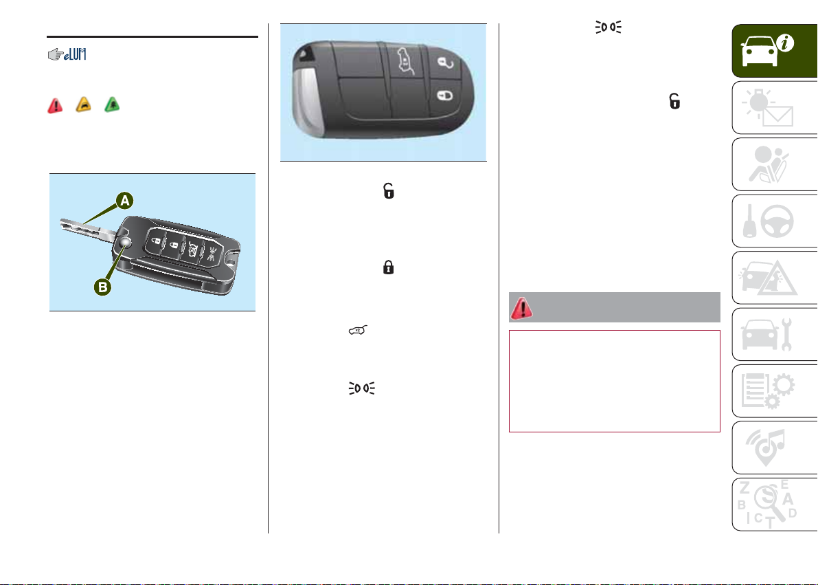
Metal insert A fig. 1 of the key operates:
❒ the ignition device;
❒ the door lock.
1
Press button B to open/close the metal
insert.
ELECTRONIC KEY
(versions with "Keyless Enter-N-Go"
system)
On versions equipped with "Keyless
Enter-N-Go" system, the vehicle
features an electronic keyfig. 2, of
which two copies are provided.
J0A0181C
2
Briefly press button
: unlocking of
J0A0315C
doors and luggage compartment, timed
switching-on of internal lights and
double flashing of direction indicators
(where provided).
Briefly press button
: lock of doors
and luggage compartment with roof
lights off and single flash of direction
indicators (where provided).
Press button
: remote opening of
the luggage compartment (to open the
luggage compartment press the button
twice in quick succession).
Press button
: remote switching
on of the main beam headlights, for
a maximum of 90 seconds.
Pressing button
again or at the
end of the 90 seconds, the lights
switched on previously will go off (if the
parking light function was already
active it will remain so). If, when 90
seconds have passed, button
is
pressed, the main beam headlights and
the side lights will stay on for further
30 seconds.
REQUEST FOR
ADDITIONAL KEYS
Should a new key with remote control
or a new electronic key be necessary,
go to a Jeep Dealership, taking an
ID document and the vehicle ownership
documents.
WARNING
1) Press button B only with the key away
from your body, especially your eyes and
from objects which could get damaged
(e.g. your clothes). Do not leave the key
unattended, to prevent people, especially
children, from inadvertently pressing the
button.
7
8
WARNING
1) The electronic components inside the
key may be damaged if the key is
subjected to strong shocks. In order to
ensure complete efficiency of the
electronic devices inside the key, it should
never be exposed to direct sunlight.
WARNING
1) Remote control used batteries may be
harmful to the environment if not disposed
of correctly. They must be disposed of
as specified by law in the special
containers or taken to a Jeep Dealership,
which will take care of their disposal.
GETTING TO KNOW YOUR CAR
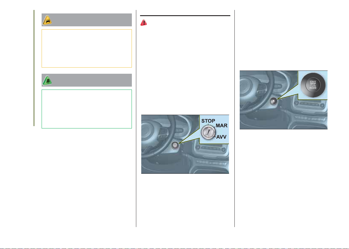
IGNITION DEVICE
2) 3) 6) 7)
VERSIONS WITH
MECHANICAL KEY
The key can be turned to three different
positions fig. 3:
❒ STOP: engine off, key can be
removed, steering column locked (with
key removed). Some electrical devices
(e.g. central door locking system,
alarm, etc.) are still available;
❒ MAR: driving position. All electrical
devices are available;
❒ AVV: engine start-up.
3
NOTE On versions with automatic
transmission the ignition key can only
be removed when the gear lever is at P
(Park).
J0A0021C
VERSIONS WITH
ELECTRONIC KEY
(Keyless Enter-N-Go system)
To activate the ignition device the
electronic key must be inside the
passenger compartment. The ignition
device fig. 4 activates also if the
electronic key is inside the luggage
compartment or on the parcel shelf.
4
J0A0022C
The ignition device can enter the
following states:
❒ STOP: engine off, steering column
locked. Some electrical devices (e.g.
central door locking system, alarm,
etc.) are still available;
❒ MAR: driving position. All electrical
devices are available. This state can be
entered by pressing the ignition device
button once, without pressing the brake
pedal (versions with automatic
transmission) or the clutch pedal
(versions with manual gearbox);
❒ AVV: engine start-up.

Starting the engine (with electronic
key battery run down): rest the
rounded edge of the electronic key (the
side opposite the metal insert) on the
button of the ignition device and press
this button through the electronic key.
Switching off the engine (with
electronic key battery run down):
hold down the button of the ignition
device or press it three times in a row
within a few seconds.
NOTE The ignition device does NOT
activate if the electronic key is inside
the luggage compartment and this
is open.
NOTE With the ignition device at MAR,
if 30 minutes pass with the vehicle
stationary (versions with manual
gearbox) or with the gear lever at P
(Park) (versions with automatic
transmission) and the engine off, the
ignition device will automatically move
to the STOP position.
For more information on the engine
start-up, see the description in the
"Starting the engine" paragraph, in the
"Starting and driving" chapter.
STEERING LOCK
Engagement
Versions with mechanical key: with the
device at STOP, remove the key and
turn the steering wheel until it locks.
IMPORTANT If the ignition key has
been moved from the MAR to the
STOP position, the steering lock cannot
engage until the key is removed from
the ignition device.
Versions with electronic key: the
steering lock engages when the driver
door is opened, with the ignition device
button at STOP and speed below 3
km/h.
Disengagement
Versions with mechanical key: slightly
moving the steering wheel, turn the key
to the MAR position.
Versions with electronic key: the
steering lock disengages when the
ignition device is pressed and the
electronic key is recognised.
4) 5)
WARNING
2) If the ignition device has been tampered
with (e.g. an attempted theft), have it
checked over by a Jeep Dealership before
driving again.
3) Always take the key with you when you
leave your vehicle to prevent someone
from accidentally operating the controls.
Remember to engage the electric parking
brake. Never leave children unattended
in the vehicle.
4) It is absolutely forbidden to carry out any
after-market operation involving steering
system or steering column modifications
(e.g. installation of anti-theft device) that
could adversely affect performance and
safety, invalidate the warranty and also
result in the vehicle not meeting typeapproval requirements.
5) Never extract the mechanical key while
the vehicle is moving. The steering wheel
will automatically lock as soon as it is
turned. This also applies to cases in which
the vehicle is towed.
6) ALWAYS engage the parking brake
before leaving the vehicle. On versions
equipped with automatic transmission,
move the gear lever to STOP (Park) and
press the ignition device to set it to STOP.
When leaving the vehicle, always lock all
the doors by pressing the dedicated button
on the handle.
9

7) On versions equipped with Keyless
Enter-N-Go system, do not leave the
electronic key inside or near the vehicle or
in a place accessible to children. Do not
leave the vehicle with the ignition device in
the MAR position. A child could operate
the electric windows, other controls or
even start the vehicle.
GETTING TO KNOW YOUR CAR
SENTRY KEY®
The Sentry Key® system, prevents
unauthorised use of the vehicle, disabling engine starting.
The system does not need to be
enabled/activated: operation is
automatic, regardless of the fact that
the vehicle's doors are locked or
unlocked.
When the ignition device is taken to
MAR, the Sentry Key® system identifies the code transmitted by the key. If
the code is recognised as valid, the
Sentry Key® system enables engine
starting.
When the ignition device is brought
back to STOP, the Sentry Key® system deactivates the control unit controlling the engine, thus preventing its
starting.
For the correct engine starting
procedures, see the instructions in the
"Starting the engine" paragraph,
"Starting and driving" chapter.
IRREGULAR OPERATION
If, during starting, the key code is not
correctly recognised, the
displayed on the instrument panel (see
the instructions in the "Warning lights
and messages" paragraph, "Knowing
the instrument panel" chapter). This
condition leads to the engine switching
off after 2 seconds. In this case, bring
the ignition device to STOP and then to
MAR; if it is still blocked, try with the
other keys provided. If it is still not
possible to start the engine, contact a
Jeep Dealership.
If the
this means that the system is running
a self-diagnosis (e.g. due to a voltage
drop). If the displaying is still on,
contact a Jeep Dealership.
icon is displayed while driving,
icon is
10
ALARM
Activation of the alarm triggers the
acoustic warning and the direction
indicators.
IMPORTANT The alarm is adapted to
meet requirements in various countries.
SWITCHING ON THE
ALARM
With the doors, bonnet and tailgate
closed and the ignition device turned to
STOP, point the key with remote control
(or electronic key) towards the vehicle
and press and release button
Except for specific markets, the system
emits a visual and acoustic signal and
enables door locking.
With the alarm on, warning light A fig. 5
flashes on the instrument panel.
.
TURNING THE ALARM
OFF
Press the
button.
IMPORTANT The alarm does not switch
off when the central opening is
activated using the metal insert in the
key.
DISABLING THE ALARM
To completely deactivate the alarm (e.g.
during a long period of vehicle
inactivity), close the doors by turning
the metal insert of the key with remote
control in the door lock.
IMPORTANT If the batteries of the key
with the remote control run out or
the system fails, the alarm can
be switched off by placing the ignition
device to MAR. On versions equipped
with Keyless Enter-N-Go system,
manually open the doors by placing the
metal insert that is in the key in the
driver side door pawl and then place
the same electronic key on the ignition
device.
DOORS
LOCKING/UNLOCKING
DOORS FROM THE
INSIDE
8)
If all doors are closed properly, they will
automatically be locked once the
vehicle has exceeded 20 km/h
("Autoclose" function).
Central locking/unlocking: press the
button
trim fig. 6 or on the passenger side
door to lock the doors. With doors
locked, press button
6
on the driver side door panel
to unlock them.
J0A0079C
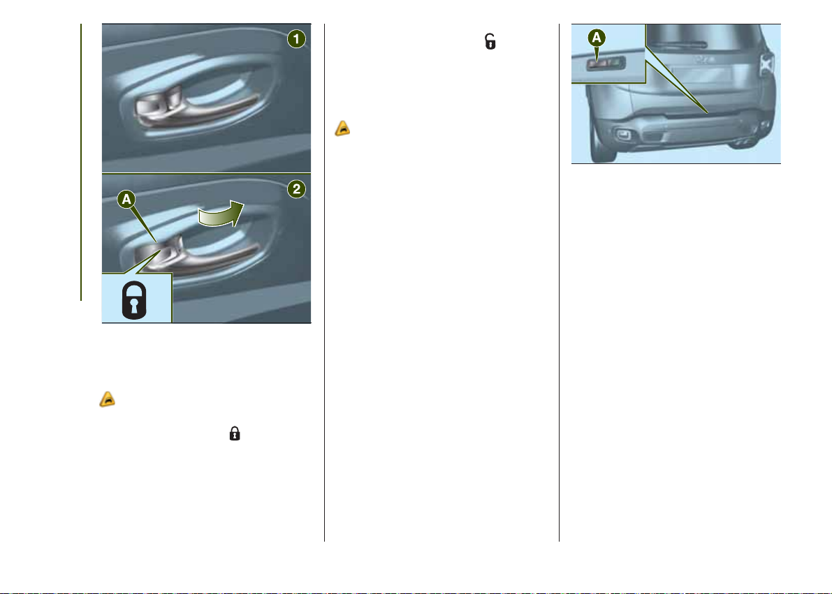
Manual locking/unlocking: use
lever A fig. 7 on the front door handle.
Position 1: door unlocked
5
J0A0191C
Position 2
: door locked
11
GETTING TO KNOW YOUR CAR
7
LOCKING/UNLOCKING
DOORS FROM THE
OUTSIDE
2)
Door locking from outside: with the
doors closed, press the
the key or fit and then turn the metal
insert (located inside the key) in the
driver side door lock.
J0A0027C
button on
Door unlocking from outside: with
the doors closed, press the
button
on the key or fit and then turn the metal
insert (located inside the key) in the
driver side door lock.
PASSIVE ENTRY
3)
The Passive Entry system can identify
the presence of an electronic key near
the doors and the tailgate. Thanks to it,
you can unlock/lock the doors (or the
tailgate) without having to press any
button on the electronic key.
If the system identifies that the
electronic key found is valid, the owner
of the key can simply grasp one of
the front handles to release the alarm
and unlock the door and tailgate
opening mechanism.
After the unlocking, pulling the opening
handle all doors can be opened
depending on the mode set through the
display menu or the Uconnect system.
You can also access the luggage
compartment by pressing the
dedicated opening button A fig. 8.
NOTE Ensure that you always have the
electronic key with you (e.g. in your
pocket) so that the system recognises it
and lets you enter the passenger
compartment and start the engine.
8
J0A0042C
Driver side door emergency
opening
If the electronic key does not work (e.g.
because its battery does not work
anymore, or the vehicle battery is flat),
the emergency metal inside the key can
be used to operate the lock unlocking
on the driver side door.
Removing the metal insert: operate
on A device fig. 9 and extract, pulling
towards outside, the metal insert B.
Then fit the metal insert in the driver
side door lock and rotate it to release
the door lock.
Door locking: make sure that you
have the electronic key and are within
the 1.5-metre operating range of the
driver or passenger side door handle.
Press button A fig. 10 on the handle:
this will lock all doors and the tailgate.
Door locking will activate the alarm
as well (where provided).
12

❒ position
: device not engaged
(door may be opened from the inside).
9
10
J0A0038C
J0A0040C
IMPORTANT After pressing the "door
locking" button, wait two seconds
before the doors can be unlocked again
using the door handle. It is therefore
possible to check whether the vehicle is
locked correctly by pulling the door
handle within 2 seconds. The doors will
not be unlocked.
Tailgate door lock locking: with
tailgate closed press button A fig. 11.
11
J0A0023C
DEAD LOCK
(where provided)
9)
This inhibits the operation of the interior
door handles and the door locking/
unlocking button.
Activating the device: the device is
enabled on all the doors by quickly
double-pressing the
button on the
key.
Deactivating the device: press button
on the key with remote control or
place the ignition device to MAR.
CHILD SAFETY DEVICE
10)
This system prevents the rear doors
from being opened from the inside.
The device A fig. 12 can only be
engaged with the doors open:
❒ position
: device engaged (door
locked);
12
J0A0041C
The device remains engaged even if the
doors are electrically unlocked.
IMPORTANT The rear doors cannot be
opened from the inside when the child
lock device is engaged.
13
WARNING
8) NEVER leave children unattended inside
the vehicle, let alone leave the vehicle
with the doors unlocked in a place that
children can access easily. Children may
seriously, or even fatally, injure themselves.
Also ensure that children do not
inadvertently operate the electric parking
brake, the brake pedal or the automatic
transmission lever.
9) Always use this device when carrying
children. After engaging the device on both
rear doors, check for proper engagement
by trying to open a rear door with the
internal handle.
10) Once the Dead Lock device has been
actuated, doors cannot be opened from
inside; for this reason, make sure there are
GETTING TO KNOW YOUR CAR
no persons left inside the vehicle.
3) The operation of the recognition system
depends on various factors, such as, for
example, any electromagnetic wave
interference from external sources (e.g.
mobile phones), the charge of the battery
in the electronic key and the presence
of metal objects near the key or the vehicle.
In these cases it is still possible to unlock
the doors by using the metal insert in
the electronic key (see description on the
following pages).
SEATS
FRONT SEATS WITH
MANUAL ADJUSTMENT
11) 4)
Longitudinal adjustment: lift the lever
A fig. 13 and push the seat fully forward
or backward.
13
12)
J0A0043C
14
WARNING
2) Make sure to take the key with you once
a door or the tailgate is locked, to prevent
locking the same key inside the vehicle.
Once it has been left inside, the key can be
collected only using the second key
supplied with the vehicle.
IMPORTANT Carry out the adjustment
while sitting on the seat involved (driver
side or passenger side).
Height adjustment: move lever B fig.
13 upwards or downwards to achieve
the required height.
Backrest angle adjustment: move
lever C fig. 13 to adjust the backrest
angle, accompanying it with the
movement of the torso (operate the
lever until the desired position is
reached, then release it).

Electric lumbar adjustment: when
the ignition device is at MAR, press
button A fig. 14 to adjust the lumbar
area support, until getting the maximum
comfort while driving.
14
J0A0399C
ELECTRICALLY
ADJUSTED FRONT SEATS
5)
The control buttons (on the outside of
the seat) can be used to adjust the
height, the lengthwise position in
relation to the vehicle and the angle of
the backrest.
Height adjustment: use the front or
rear part of the switch A fig. 15 to
modify the height and/or the angle of
the seat cushion.
Longitudinal adjustment: press
switch A forwards or backwards to
move the seat in the corresponding
direction.
15
J0A0044C
Backrest angle adjustment: press
switch B forwards or backwards to
adjust the backrest angle.
Electric lumbar adjustment: use the
joystick C to actuate the lumbar area
device until getting top comfort while
driving.
FRONT SEAT ELECTRIC
HEATING
With ignition device at MAR, press the
fig. 16 buttons.
16
J0A0047C
Two heating levels can be selected:
"minimum heating" (one orange LED lit
on the buttons) / "maximum heating"
(two orange LEDs lit on the buttons).
After selecting one heating level, you
need to wait for a few minutes until
warm air flows into the compartment.
IMPORTANT To preserve the battery
charge, this function cannot be
activated when the engine is off.
REAR SEATS
Partial extension of the
luggage compartment (1/3
or 2/3)
6)
Proceed as follows:
❒ remove the parcel shelf, if present;
❒ completely lower the rear seat head
restraints;
❒ move the seat belt to the side,
making sure that it is fully extended and
not twisted;
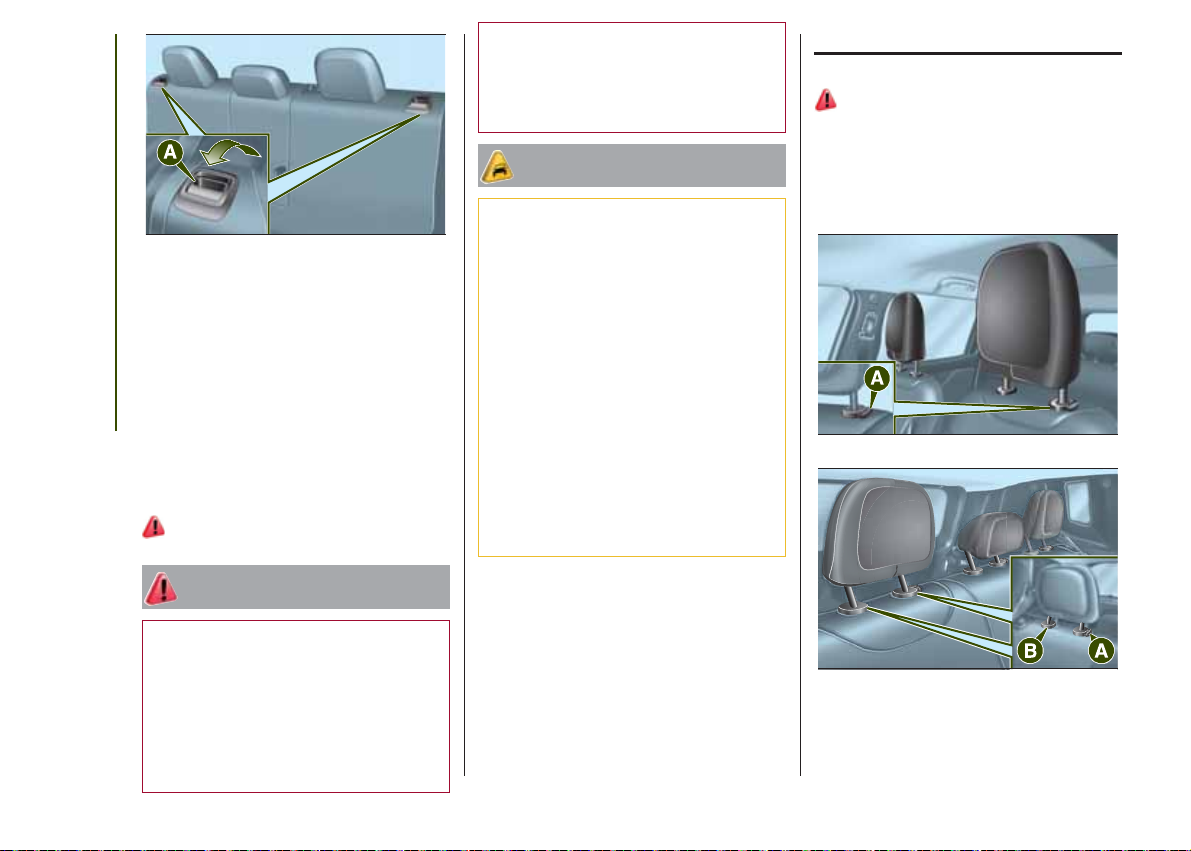
❒ actuate lever A fig. 17 to tilt the left or
right part of the backrest: it will
automatically tilt forward. If necessary,
accompany the backrest during the
initial stage of tilting. When you lift the
lever, you will see a red mark.
15
17
Repositioning the backrests
Move the seat belts to the side,
making sure that they are correctly
extended and not twisted.
Lift up the backrests and push them
back until a click is heard for both
hooking mechanisms, at the side. Make
GETTING TO KNOW YOUR CAR
sure that "red marks" on levers A fig.
17 are not visible any more. The "red
mark" means that the backrest was not
hooked properly.
13)
WARNING
J0A0045C
13) Make sure that the backrests are
correctly secured on both sides ("red
marks" not visible) to prevent it from
moving forward in the event of sharp
braking, causing injuries to occupants.
WARNING
4) The fabric upholstery for the seats has
been designed to withstand long-term
wear deriving from normal use of the
vehicle. Nevertheless, some precautions
are required. Avoid prolonged and/or
excessive rubbing involving clothing
accessories such as metal buckles,
bosses, Velcro strips and the like, which,
by applying a high pressure on the fabric in
a limited area, could cause it to break,
thereby damaging the upholstery.
5) Do not arrange objects beneath the
electrically adjustable seat and do not
impede its movement, since the controls
may be damaged. They may also restrict
the seat travel.
6) Before tilting the backrest, remove any
objects laying on the seat.
HEAD RESTRAINTS
ADJUSTMENTS
14)
Upwards adjustment: raise the head
restraint until it clicks into place.
Downwards adjustment: press
button A fig. 18 and fig. 19 and lower
the head restraint.
18
J0A0057C
16
11) Any adjustment must be performed
with the vehicle at a standstill.
12) After releasing the adjustment lever,
always check that the seat is locked on the
guides by trying to move it back and forth.
If the seat is not locked into place, it may
unexpectedly slide and cause the driver to
lose control of the vehicle.
19
J0A0058C
REAR HEAD RESTRAINTS
(removal)
Proceed as follows to remove the head
restraints:
❒ raise the head restraints to their
maximum height;
❒ press buttons A and B fig. 19 at the
side of the two supports, then remove
the head restraints by pulling them
upwards.
STEERING WHEEL
15) 16)
ADJUSTMENTS
The steering wheel can be adjusted
both in height and in depth.
To adjust, move lever A fig. 20
downwards to position 1, then adjust
the steering wheel to the most suitable
position and lock it in position by
moving lever A to position 2.
21
J0A0048C
WARNING
14) The head restraints must be adjusted
so that the head, rather than the neck,
rests on them. Only in this case can they
protect your head correctly.
20
J0A0056C
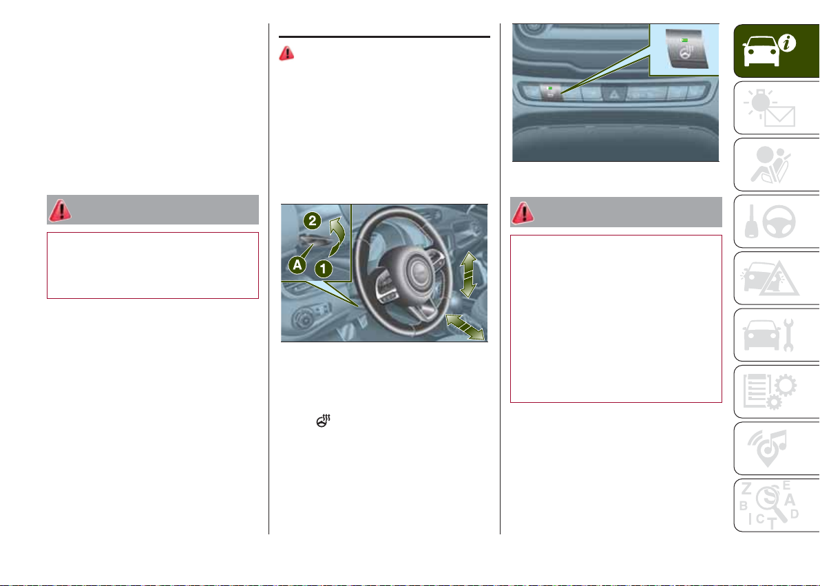
ELECTRIC STEERING
WHEEL HEATING
With ignition device at MAR, press
button
on the dashboard fig. 21.
When the function is enabled, the LED
on the button switches on.
IMPORTANT If this function is activated
with engine off the battery may run
down.
WARNING
15) Any adjustment of the steering wheel
position must be carried out only with
the vehicle stationary and the engine
turned off.
16) It is absolutely forbidden to carry out
any after-market operations involving
steering system or steering column
modifications (e.g. installation of anti-theft
device) that could adversely affect
performance and safety, invalidate the
warranty and also result in the vehicle not
meeting type-approval requirements.
17
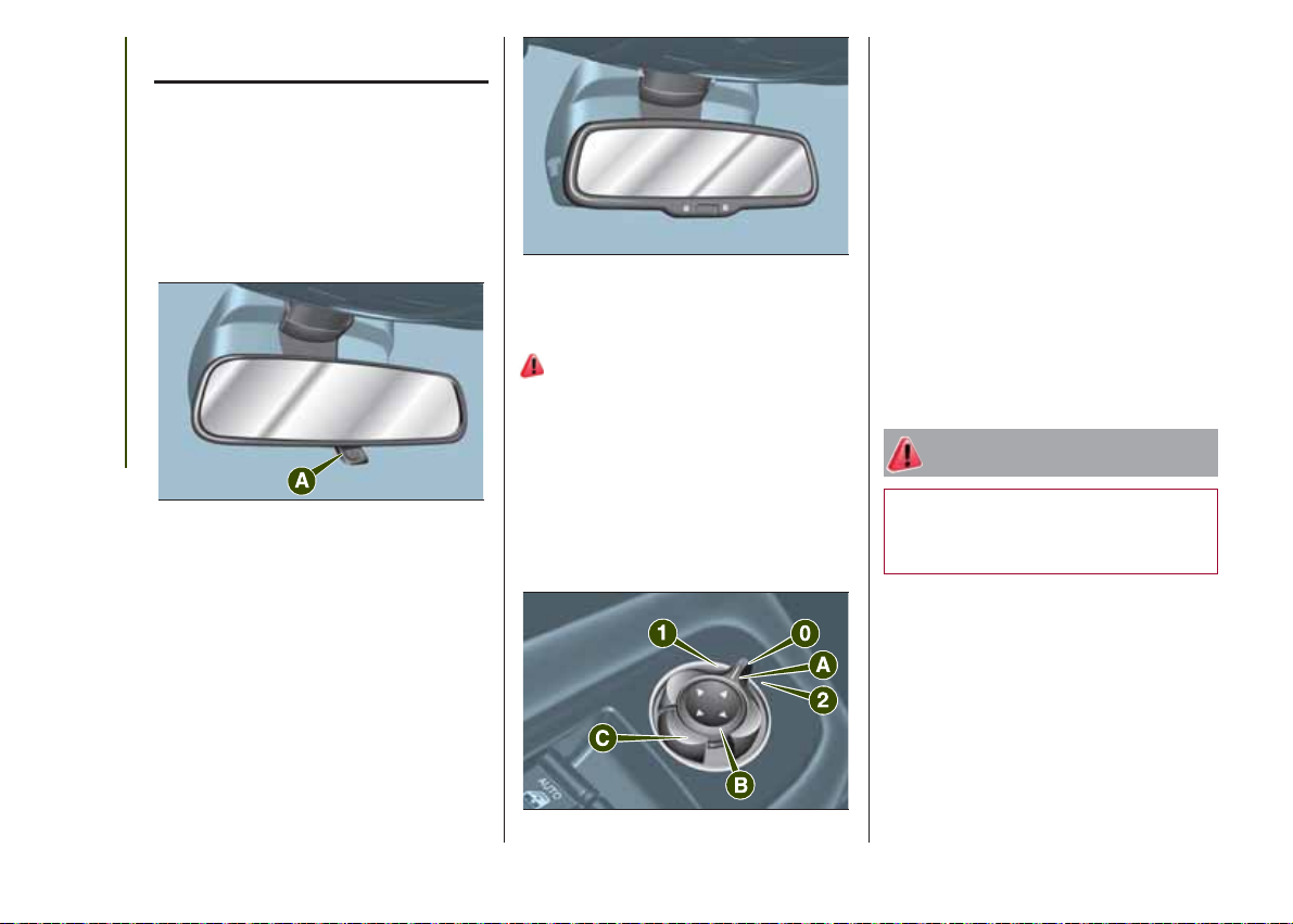
REAR VIEW
MIRRORS
INTERIOR MIRROR
The mirror is fitted with a safety device
that causes its release in the event of
a violent impact with the passenger.
Operate lever A fig. 22 to adjust the
mirror into two different positions:
normal or anti-glare.
GETTING TO KNOW YOUR CAR
22
ELECTROCHROMIC
INTERIOR MIRROR
On some versions, an electrochromic
mirror is available, that can
automatically modify its reflecting action
to prevent dazzling the driver fig. 23
The electrochromic mirror has an
ON/OFF button to activate/deactivate
the electrochromic anti-glaring function.
J0A0060C
23
J0A0059C
DOOR MIRRORS
Electric adjustment
17)
The mirrors can only be adjusted with
the ignition device at MAR.
Select the desired mirror using device A
fig. 24:
❒ device in position 1: left mirror
selected;
❒ device in position 2: right mirror
selected.
To adjust the selected mirror, press
button B fig. 24 in the four directions
shown by the arrows.
IMPORTANT Once adjustment is
complete, rotate device A fig. 24 to
position 0 to prevent accidental
movements.
Electrical mirror folding
To fold the mirrors, press button C fig.
24. Press the button again to restore
the mirrors to the driving position.
WARNING The mirrors must always be
open while driving and should never
be folded.
WARNING
17) As the driver's door mirror is curved, it
may slightly alter the perception of
distance.
18
24
J0A0061C
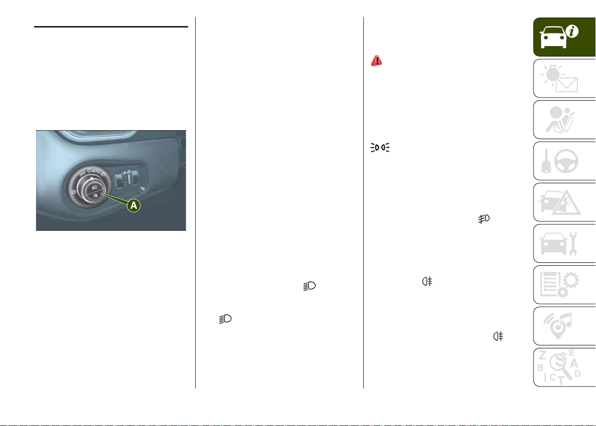
EXTERIOR LIGHTS
LIGHT SWITCH
Light switch A fig. 25, located on the
left side of the dashboard, controls
operation of headlights, side lights,
daytime running lights, dipped beam
headlights, fog lights, rear fog lights and
instrument panel indicator and control
button graphic lighting regulation.
25
The exterior lights can only be switched
on when the ignition device is at MAR.
The instrument panel and the various
controls on the dashboard will be lit up
when the exterior lights are switched
on.
J0A0062C
AUTO FUNCTION
(Dusk sensor)
(where provided)
This is an infrared LED sensor that
works in conjunction with the rain
sensor and is located on the
windscreen. It is able to detect
variations in outside lighting based on
the light sensitivity and adjusts the
display Menu or the Uconnect™
system.
The higher the sensitivity, the lower the
amount of external light needed to
switch the lights on.
Function activation: turn the light
switch to AUTO.
Function deactivation: turn the light
switch to a position other than AUTO.
IMPORTANT This function can only
be activated with the ignition device at
MAR.
DIPPED BEAM
HEADLIGHTS
Turn the ignition switch to
to switch
on the side lights, the instrument panel
lights and the dipped beam headlights.
The
warning light switches on in
the instrument panel.
DAYTIME RUNNING
LIGHTS (DRL)
"Daytime Running Lights"
(where provided)
18) 19)
With the ignition device turned to MAR
and the light switch turned to position
O the daytime running lights are
automatically activated; the other lights
and interior lighting remain off.
With the ignition device turned to STOP,
bring the light switch to position
to switch on the side lights, the
instrument panel lights and to switch off
the daytime running lights.
FOG LIGHTS
(for versions/markets where provided)
With side lights and dipped beam
headlights on, press switch
to
switch on the fog lights.
To switch off the fog lights press the
switch again or turn it to position O.
REAR FOG LIGHT
Press button
to switch the light
on/off.
The rear fog light switches on only
when the dipped beam headlights or
fog lights are switched on. The light
switches off by pressing button
or
by switching off the main beam
headlights or the fog lights.
19

PARKING LIGHTS
These lights can be switched on with
ignition device at STOP or with key
removed, by moving the light switch to
position O and then to position
The
in the instrument panel.
HEADLIGHTS OFF TIMER
Function activation: with lights on,
bring the ignition device to STOP. Then
switch off the headlights within 45
seconds: timing will start when the light
switch is turned to O.
IMPORTANT To activate this functions
the headlights must be deactivated
within 45 seconds after the ignition
GETTING TO KNOW YOUR CAR
device has been taken to STOP.
Function deactivation: this function is
deactivated by switching on the
headlights, the side lights or bringing
the ignition device to MAR. If the
headlights are switched off before
ignition, they will go out normally.
MAIN BEAM HEADLIGHTS
To activate the fixed main beam
headlights push left lever A fig. 26
(vehicle travel direction). The light
switch must be turned to AUTO or
The unstable position is activated by
pulling the lever towards you.
warning light switches on
.
With main beam headlights on, the
warning light on the instrument
panel will come on at the same time.
.
26
The main beam headlights are
deactivated bringing the lever back to
the central stable position. Warning light
switches off in the instrument
panel.
Automatic main beam
headlights
This function is enabled with the display
Menu or the Uconnect™ system,
and with the light switch turned to
AUTO.
The first time the main beam headlights
are activated (pushing the left lever),
the function is activated (green warning
light
panel).
If the main beam headlights are actually
on, the blue warning light
come on in the instrument panel.
come on in the instrument
J0A0063C
will also
To deactivate the automatic function
rotate the light switch ring nut to
position
DIRECTION INDICATORS
Bring left lever A fig. 26 to the (stable)
position:
❒ upwards: activates the right direction
indicator;
❒ downwards: activates the left
direction indicator.
"Lane Change" function
If you wish to signal a lane change,
place the left lever in the unstable
position for less than half a second. The
direction indicator on the side selected
will flash five times and then switch
off automatically.
HEADLIGHT ALIGNMENT
ADJUSTMENT
Headlight alignment
corrector
This device only works with the ignition
device at MAR and the dipped beam
headlights on.
To adjust rotate ring nut A fig. 27.
❒ Position 0: one or two people on the
front seats;
❒ Position 1: 4 passengers
❒ Position 2: 4 passengers + load in
the luggage compartment
.
20

WARNING
INTERIOR LIGHTS
27
J0A0064C
❒ Position 3: driver + maximum
permitted load stowed only in the
luggage compartment
IMPORTANT Check the headlight
alignment each time the weight of the
load transported changes.
INSTRUMENT PANEL AND
CONTROL BUTTON
GRAPHICS BRIGHTNESS
ADJUSTMENT
With side lights or headlights on, turn
ring nut B fig. 27 upwards to increase
light brightness of the instrument panel
and of the control button graphics, or
turn the ring nut downwards to
decrease it.
18) The daytime running lights are an
alternative to the dipped beam headlights
for driving in countries where it is
compulsory to have lights on during the
day; where it is not compulsory, the use of
daytime running lights is permitted.
19) Daytime running lights cannot replace
dipped beam headlights when driving at
night or through tunnels. The use of
daytime running lights is governed by the
highway code of the country in which
you are driving. Comply with legal
requirements.
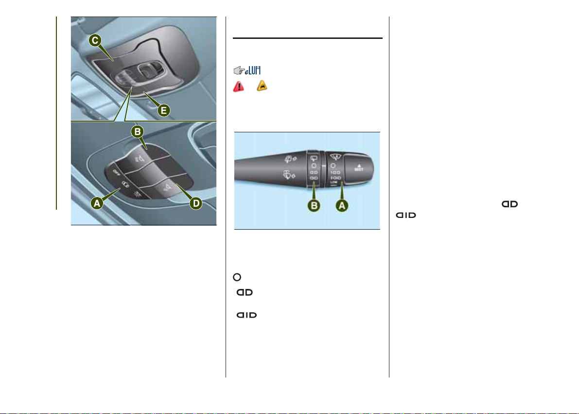
FRONT COURTESY
LIGHTS
Switch A fig. 28 is used to switch on/off
the courtesy lights bulbs.
Switch positions:
❒ central position: lights C and E switch
on/off when the doors are opened/
closed;
❒ pressed to the left (position OFF):
lights C and E are always switched off;
❒ pressed to the right (position
):
lights C and D are always switched on.
The lights switch on/off gradually.
Switch B fig. 28 switches light C on/off.
Switch D fig. 28 switches light E on/off.
21
22
GETTING TO KNOW YOUR CAR
28
Courtesy light timing
On certain versions, to facilitate getting
in/out of the vehicle at night or in
poorly-lit areas, two timed modes have
been provided.
❒ when getting into the vehicle;
❒ when getting out of the vehicle.
J0A0024C
WINDSCREEN/REAR
WINDOW WIPER
WINDSCREEN
WIPER/WASHER
20) 7) 8)
This operates only with the ignition
device at MAR.
29
Ring nut A fig. 29 can be set to the
following positions:
windscreen wiper off.
1
intermittent operation (low
speed)
2
intermittent operation (high
speed);
LOW
continuous slow operation.
HIGH
continuous fast operation.
J0A0071C
Move the stalk upwards (unstable
position) to activate the MIST function:
operation is limited to the time for which
the stalk is held in this position. When
released, the stalk will return to its
default position and the windscreen
wiper will be automatically stopped.
This function is useful to remove small
deposits of dust from the windscreen,
or morning dew.
IMPORTANT This function does not
activate the windscreen washer;
windscreen washer fluid will not
therefore be sprayed onto the
windscreen. To spray windscreen
washer fluid onto the windscreen, the
washing function must be used.
With ring nut A in position 1
or 2
, the windscreen wiper will
automatically adapt its operating speed
to the speed of the vehicle.
"Smart washing" function
Pull the lever towards the steering
wheel (unstable position) to operate the
windscreen washer.
Keep the stalk pulled to activate both
the windscreen washer jet and the
windscreen wiper with a single
movement; the latter turns on
automatically.
The wiper stops working three strokes
after the stalk is released. A further
stroke after approximately 6 seconds
completes the cycle.
RAIN SENSOR
(where provided)
This is located behind the interior rear
view mirror, in contact with the
windscreen and can detect the
presence of rain and, consequently,
manage the cleaning of the windscreen
in accordance with the amount of
water on the screen.
Activation/deactivation
9) 10)
By acting on the display menu or on the
Uconnect™ system you can
activate/deactivate the rain sensor. The
sensor can also be deactivated by
bringing the ignition device to STOP.
The activation of the sensor is signalled
by a "stroke" to show that the
command has been acquired.
If the ignition device is moved to STOP
position, leaving the ring nut A fig. 29
in 1
or 2
, when the vehicle is
next started (ignition device at MAR),
no wiping cycle occurs even if it rains.
REAR WINDOW
WIPER/WASHER
Activation
Turn ring nut B fig. 29 from position O
to position
to operate the rear
window wiper as follows:
❒ in intermittent mode when the
windscreen wiper is not operating;
❒ in synchronous mode (at half the
speed of the windscreen wiper) when
the windscreen wiper is operating;
❒ in continuous mode with reverse gear
engaged and the control active.
Position 1
: intermittent operation
(low speed).
Position 2
: continuous slow
operation.
With reverse gear engaged and
windscreen wiper on, the rear window
wiper is activated in continuous mode.
Pushing the stalk towards the
dashboard (unstable position) will
activate the rear window washer jet.
Keep the stalk pushed for more than
half a second to activate the rear
window wiper as well. Releasing the
stalk will activate the smart washing
function, as described for the
windscreen wiper.
Deactivation
Release the lever.
WARNING
20) Make sure the device is switched off
whenever the windscreen must be
cleaned.
WARNING
7) Do not use the screen wiper to remove
layers of snow or ice from the windscreen.
In such conditions, the windscreen wiper
may be subjected to excessive stress
and the motor cut-out switch, which
prevents operation for a few seconds, may
intervene. If operation is not subsequently
restored, even after the vehicle is restarted,
contact a Jeep Dealership.
8) Do not operate the windscreen wiper
with blades lifted from the windscreen.
9) Do not activate the rain sensor while
washing the vehicle in an automatic
washing system.
10) If ice is found on the windscreen, make
sure that the device was disconnected
properly.
23
CLIMATE CONTROL
2)
.
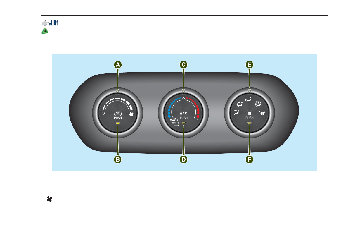
MANUAL CLIMATE CONTROL SYSTEM
Controls
GETTING TO KNOW YOUR CAR
30
A - fan activation/adjustment knob:
❒ 0 = fan off
❒
= fan speed (7 different speeds can be chosen)
B - air recirculation activation/deactivation button (LED on: internal air recirculation on / LED off: internal air recirculation off);
C - air temperature adjustment and MAX A/C function activation knob (to obtain maximum cooling of the passenger
compartment move the knob to the position marked by wording MAX A/C): blue section = cold air / red section = hot air
D - climate control system compressor on/off button;
J0A0053C
24

E - air distribution knob:
air from central outlets and side vents
air from central outlets, side vents and front and rear footwell vents
air outlet from the front and rear footwell vents and a light air flow also from the side vents on the dashboard
air outlet from the front and rear footwell vents, to the windscreen, the side windows and a light air flow also at the side
vents on the dashboard
air outlet to the windscreen, the side windows and a light air flow also at the side vents on the dashboard
4 further intermediate positions are also possible in the 5 main distributions described above.
F - heated rear window on/off button and, where provided, door mirror electric heating;
IMPORTANT Do not affix stickers to the inside of the heated rear window over the heating filaments, to avoid damage that
might cause them to stop working properly.
IMPORTANT Internal air recirculation makes it possible to reach the required heating or cooling conditions more quickly
depending on the mode selected. Do not use the internal air recirculation function on rainy/cold days as it would considerably
increase the possibility of the windows misting.
Additional heater
(where provided)
The additional heater ensures more
rapid passenger compartment heating.
It activates in cold weather conditions,
if the following conditions are verified:
❒ outside temperature low;
❒ engine coolant temperature low;
❒ engine on;
❒ fan speed set at least to 1st speed;
❒ knob C turned completely clockwise
to red section.
The heater is switched off when at least
one of the conditions above is no
longer verified.
Note The power of the electric heater is
modulated according to the battery
voltage.
WARNING
2) The system uses R1234YF coolant,
which does not pollute the environment in
the event of accidental leakage. Under
no circumstances use R134a and R12
fluids, which are incompatible with the
components of the system.
25
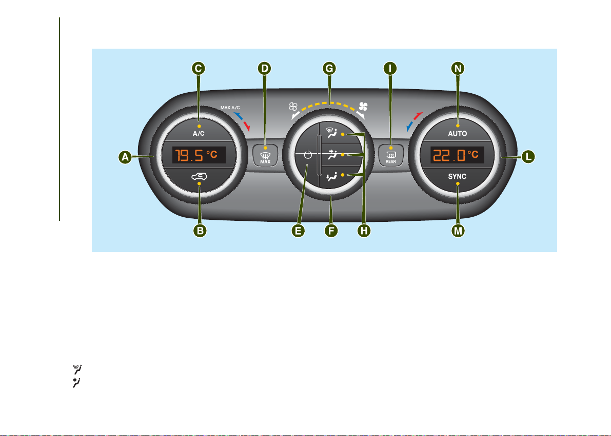
AUTOMATIC DUAL ZONE CLIMATE CONTROL SYSTEM
Controls
GETTING TO KNOW YOUR CAR
26
31
A - driver side temperature adjustment knob;
B - internal air recirculation on/off button;
C - climate control system compressor on/off button;
D - MAX-DEF function activation button (rapid defrosting/demisting of front windows);
E - climate control on/off button;
F - fan speed adjustment knob;
G - Fan speed indicator LED; (maximum fan speed = all LEDs lit; minimum fan speed = one LED lit);
H - air distribution selection buttons;
Air flow to the windscreen and front side window diffusers to demist/defrost them.
Air flow at central and side dashboard vents to ventilate the chest and the face during the hot season.
J0A0054C
Air flow to the front and rear footwell diffusers. This air distribution setting heats the passenger compartment most quickly,
giving a prompt sensation of warmth.
+
Air flow distributed between footwell diffusers (hotter air) and central and side dashboard vents (cooler air). This
distribution setting is useful in spring and autumn on sunny days.
+
Air flow distributed between footwell diffusers and windscreen and front side window defrosting/demisting diffusers.
This distribution setting allows the passenger compartment to be warmed up efficiently and prevents the windows
from misting up.
+
Air flow distribution between windscreen demisting/defrosting diffusers and side and central dashboard vents. This
allows air to be sent to the windscreen in conditions of strong sunlight.
+ +
I - heated rear window on/off button; (where this function is provided, pressing the button also activates demisting/defrosting of
the door mirrors);
L - passenger side temperature adjustment knob;
M - SYNC function activation button (alignment of set temperatures) driver/passenger side;
N - AUTO function activation button (automatic operation).
Air flow distribution to all diffusers on the vehicle.
In AUTO mode, the climate control
system automatically manages air
distribution (the LEDs on buttons H are
off). When set manually, the air
distribution is shown by the LEDs on
the selected buttons.
In combined function mode the relevant
function is enabled simultaneously
with those already set by pressing the
corresponding button. If a button
whose function is already active is
pressed, its operation is cancelled and
the corresponding LED switches off.
To restore automatic control of the
air distribution after a manual selection,
press the AUTO button.
NOTES
The automatic climate control manages
the Stop/Start system (engine off and
vehicle at a standstill) in order to
guarantee sufficient comfort inside the
vehicle. In particularly severe climate
conditions it is recommended to limit
the use of the Stop/Start system to
prevent the compressor from
continuously switching on and off, with
consequent rapid misting of the
windows and accumulation of humidity
with unpleasant smells in the passenger
compartment.
When the Stop/Start system is on
(engine off and vehicle at a standstill),
the automatic recirculation
management is turned off always taking
air in from outside, to reduce the
probability of the windows misting up
(as the compressor is off).
27
ELECTRIC WINDOWS
ELECTRIC WINDOWS
21)
They operate with the ignition device at
MAR and for nearly 3 minutes after
the ignition device switches to STOP (or
also after the mechanical key has
been extracted, for vehicles equipped
with mechanical key with remote
control). When one of the front doors is
opened this operation is disabled.
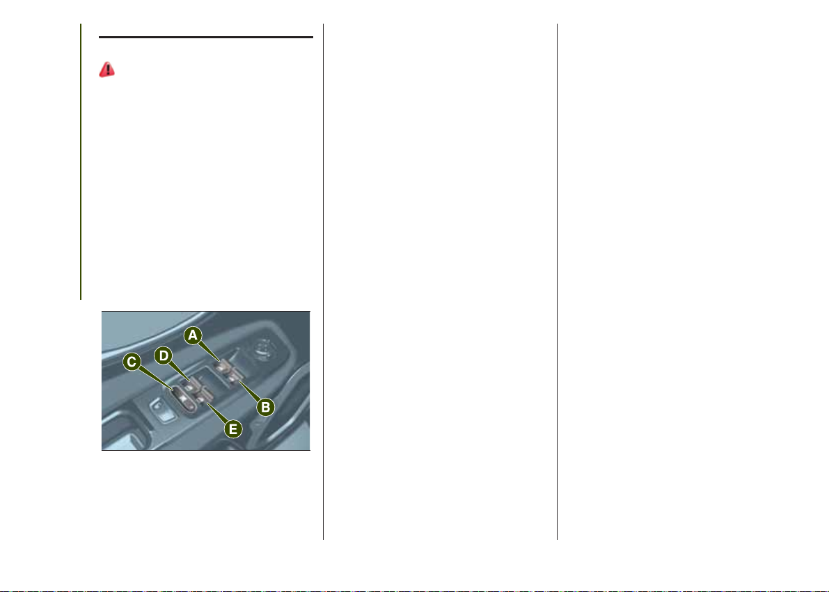
Driver side front door
controls
The buttons are located on the door
panel trim. All windows can be
controlled from the driver side door
panel fig. 32.
GETTING TO KNOW YOUR CAR
32
❒ A: front left window opening/closing.
"Continuous automatic" operation
during window opening/closing stage
and anti-pinch system activated.
J0A0078C
❒ B: right front window opening/
closing. "Continuous automatic"
operation during window opening/
closing stage and anti-pinch system
activated.
❒ C: enabling/disabling of rear door
electric window controls;
❒ D: left rear window opening/closing (if
present). "Automatic continuous"
operation during window opening/
closing, manual electric operation
during window closing;
❒ E: right rear window opening/closing
(if present). "Automatic continuous"
operation during window opening/
closing, manual electric operation
during window closing.
Window opening
Push the buttons to open the desired
window.
When any of the opening buttons on
front or rear doors is pressed briefly, the
window moves in stages; if the button
is held down, "continuous automatic"
operation is activated.
If the button is pressed again, the
window will stop in the desired position.
Window closing
Lift the buttons to close the desired
window.
The window closing stage occurs
following the same logic described for
the opening stage, for the front door
windows only.
The rear door windows can only be
closed "in stages".
Front window anti-pinch
safety device
(where provided)
This safety system can recognise the
presence of any obstacle during the
window closing movement. If this
occurs, the system stops the window's
movement and reverts it by a few
centimetres, depending on its position.
The anti-crush safety function is
activated both during the manual and
the automatic operation of the window.
Electric window system
initialisation
If power supply is interrupted, the
electric window automatic operation
must be reinitialised.
The initialisation procedure described
below must be carried out with the
doors closed and for each door:
❒ fully close the window to be
initialised, with manual operation;
28

❒ after the window has reached the
upper end of travel, hold the up button
down for at least 3 seconds.
ELECTRIC SUN
ROOF
WARNING
21) Incorrect use of the electric windows
may be dangerous. Before and during their
operation, ensure that any passengers
are not at risk from the moving glass either
by personal objects getting caught in the
mechanism or by being hit by it directly.
When leaving the vehicle (equipped with
mechanical key with remote control),
always remove the key from the ignition
device to prevent accidental operation of
the electric windows from being a hazard
for those still on board.
22) 11)
The electric sun roof comprises two
glass panels (the front one is mobile
and the rear one fixed) and is fitted with
an electrically operated sun blind.
The sun roof and the blind can
be operated only with the ignition
device turned to MAR.
CONTROL BUTTONS
Button A fig. 33: pressing the button
on the front glass panel, it will
completely open. From the position of
complete opening, pull the button:
the front panel will completely close.
During the automatic opening and
closing stages, press button A again to
interrupt the blind movement.
Button B fig. 33: pressing this button,
the blind will mode towards the rear
part of the vehicle, until it is fully open.
With blind fully open press button B:
the blind will move towards the front
part of the vehicle, until it is fully closed.
During the automatic opening and
closing stages, press button B again to
interrupt the blind movement.
33
J0A0224C
Button C fig. 33: press and release the
button to move the roof to "spoiler"
position (swivel opening). This type of
swivel opening can be activated
irrespective of the position of the sun
roof. During the spoiler opening, any
pressure on button C stops the roof
closing.
29

ANTI-PINCH DEVICE
The sun roof and the electric blind are
equipped with an anti-pinch safety
system capable of detecting the
presence of an obstacle whilst the roof
is closing: if this happens, the system
intervenes and the movement of the
glass is immediately reversed.
EMERGENCY OPERATION
If the control buttons fail to operate, the
sun blind and the sun roof can be
moved manually, proceeding as
described below:
❒ Sun blind movement: remove
protective cap A fig. 34 on the internal
trim;
❒ Sun roof movement: remove
GETTING TO KNOW YOUR CAR
protective cap B fig. 34 on the internal
trim;
34
❒ take the supplied spanner C fig. 34
from the luggage compartment;
J0A00390C
❒ insert key C in housing A (for blind
movement) or B (for sun roof
movement) and turn it clockwise to
open the roof (or the blind) or
anticlockwise to close the roof (or the
blind).
INITIALISATION
PROCEDURE
Following an automatic movement
malfunction while opening/closing or
after an emergency manoeuvre (see
description in the previous paragraph),
the automatic operation of the sun
roof must be initialised again.
Proceed as follows:
❒ move the roof to fully closed position;
❒ move the ignition device to STOP
and keep it there for 10 seconds;
❒ move the ignition device to MAR;
❒ press button A in closing position;
❒ press the button for at least 10
seconds, then you should hear the
mechanical stop of the roof motor;
❒ press the button A in the "closing"
position again within 5 seconds;
❒ hold down button A: in this position,
the roof will perform an automatic
opening and closing cycle. Otherwise,
repeat the operations starting from
the beginning;
❒ hold down button A until the roof is
completely closed: the initialisation
procedure has ended.
WARNING
22) When leaving the vehicle (equipped
with mechanical key with a remote control),
always remove the key from the ignition
device to avoid the risk of injury to those
still inside the vehicle due to accidental
operation of the sun roof. Improper use of
the roof can be dangerous. Before and
during operation, always check that
nobody is at risk of being injured by the
moving sun roof or by objects getting
caught or hit by it.
WARNING
11) Do not open the sun roof if a
transverse roof rack is fitted. Do not open
the sun roof if there is snow or ice on it:
you may damage it.
30

MySky SUN ROOF
12)
The roof has two panels, a front and a
rear one, that can be individually or
simultaneously removed, as wished.
Front and rear panels are distinguished
by a dedicated symbol on the bottom
of the panels themselves.
IMPORTANT The panels can withstand
any snow that may deposit on them.
In any case, it is advisable to remove
excessive snow.
FRONT PANEL ELECTRIC
MOVEMENT
On some versions, the front panel
might be electrically operated. This
operates only with the ignition device at
MAR. The panel can be adjusted
forward/backward and opened in swivel
position.
The buttons to operate the front panel
are located on the trim close to the
front roof light fig. 35:
❒ Button A: opening/closing button
until the end of stroke of the front panel.
Pressing the button on the front glass
panel will completely open it. From
the position of complete opening pull
the button: the front panel will
completely close.
❒ Button B: opening button for swivel
position of the front panel. To bring
the roof into swivel position, press and
release the button. This opening mode
can be activated with fully closed roof
only. With open panel, or with partially
open panel, the button B will be
deactivated. During the swivel opening,
any pressure on the button stops the
roof closing.
35
J0A0225C
Anti-pinch device
The front panel has an anti-pinch safety
system capable of detecting the
presence of an obstacle whilst the
panel is being opened and closed.
When this happens, the system stops
and the movement of the panel is
immediately reversed.
PANEL REMOVAL
IMPORTANT Remove the panels only
when the vehicle is at a standstill.
The rear panel can be removed only
when the front panel is fully closed
or removed.
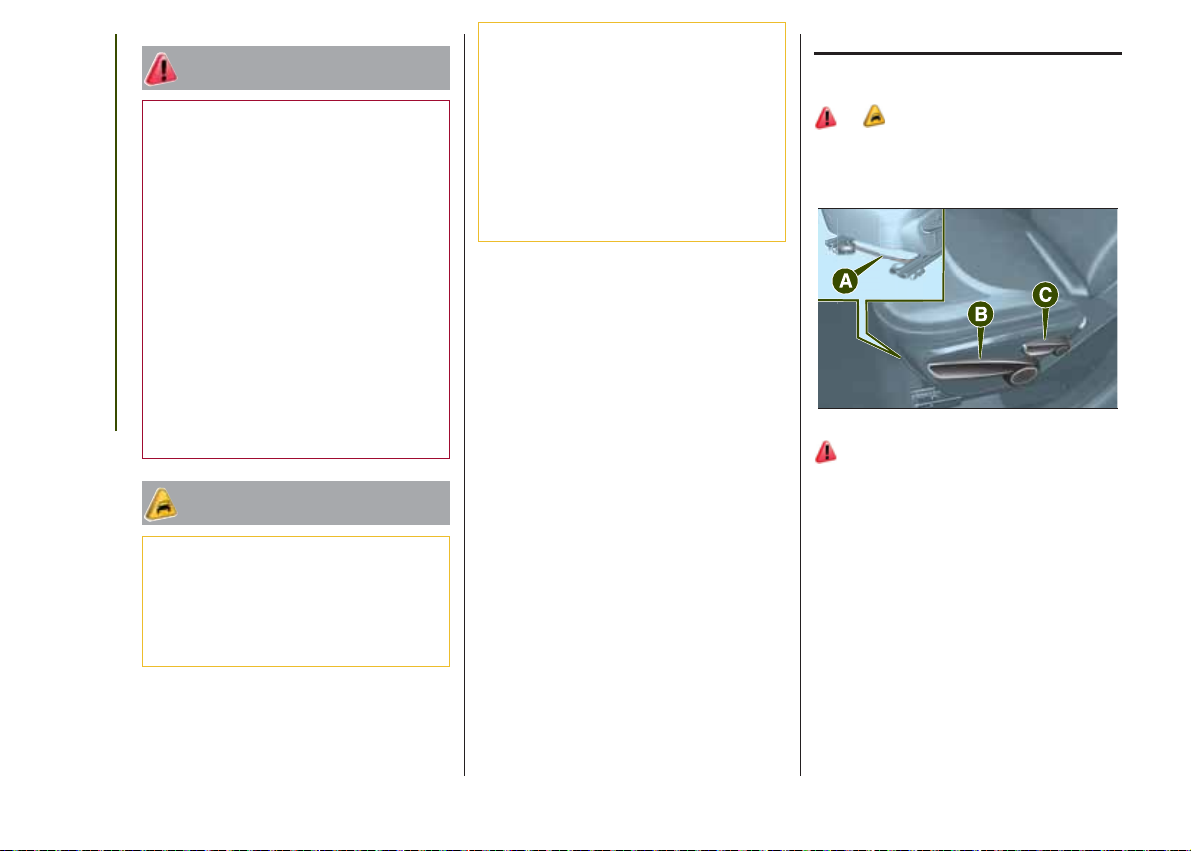
Proceed as follows to remove the
panels:
❒ working inside the passenger
compartment, fit the spanner A fig. 36
inside the housing B fig. 37, rotate it
and continue rotating it next to the
symbol, so that the door lock is
released; at the same time, fully pull the
handle C (on the same panel) to the
end of travel;
❒ remove the panel (front or rear), or
both;
❒ place the panel (or both panels)
inside the dedicated suitcase (see the
following pages) and arrange it in the
luggage compartment.
31

❒ close the suitcase and position it
properly inside the luggage
compartment;
❒ secure the suitcase firmly to the
retaining hooks on the luggage
compartment crossmember.
EMERGENCY OPERATION
If the control buttons fail to operate, the
sun roof can be moved manually,
proceeding as described below:
32
36
GETTING TO KNOW YOUR CAR
37
PANEL STORAGE
SUITCASE
After removing the roof panels, they
must be positioned inside the
dedicated suitcase inside the luggage
compartment. It is recommended to
perform this procedure from outside the
vehicle.
Proceed as follows:
❒ open the suitcase, position the first
panel B as shown in fig. 38 and then
position the second panel C;
J0A0272C
J0A0271C
38
J0A0416C
IMPORTANT Never put excess loads
on the suitcase; for further information,
see the description in the documents
supplied with the suitcase.
39
J0A0080C
❒ remove protective cap A fig. 39 on
the internal trim;
❒ introduce the supplied key B into
housing A and turn it clockwise to open
the roof or anticlockwise to close it.
WARNING
12) Do not open the sun roof if a
transverse roof rack is fitted. Do not open
the sun roof if there is snow or ice on it:
you may damage it.

BONNET
OPENING
Proceed as follows:
❒ pull lever A fig. 40 in the direction
indicated by the arrow;
40
❒ operate lever B fig. 41, in the
direction indicated by the arrow, and
raise the bonnet;
41
J0A0068C
J0A0069C
❒ release bonnet stay C fig. 42 from its
locking device D, then insert its end
in housing E on the bonnet.
42
23) 24)
J0A0070C
CLOSING
Proceed as follows:
❒ hold the bonnet up with one hand
and with the other remove the stay from
the housing E and fit it back in locking
device D;
❒ lower the bonnet to approximately 40
centimetres from the engine
compartment and let it drop. Make sure
that the bonnet is completely closed
and not only fastened by the locking
device by trying to open it. If it is not
perfectly closed, do not try to press the
bonnet lid down but open it and repeat
the procedure.
25) 26)
IMPORTANT Always check that the
bonnet is closed correctly to prevent it
from opening while the vehicle is
travelling. Since the bonnet is equipped
with a double locking system, one for
each side, you must check that is
closed on both its side ends.
WARNING
23) Wrong positioning of the bonnet stay
may cause the bonnet to fall abruptly.
24) Raise the bonnet using both hands.
Before raising the bonnet make sure that
the windscreen wipers are not lifted from
the windscreen and are operating, that the
vehicle is at a standstill and that the electric
parking brake is engaged.
33

25) For safety reasons the bonnet must
always be correctly closed while driving.
Therefore, make sure that the bonnet
is properly closed and that the lock
is engaged. If you discover that the bonnet
is not perfectly closed during travel, stop
immediately and close the bonnet in the
correct manner.
26) Perform these operations only when
the vehicle is stationary.
GETTING TO KNOW YOUR CAR
LUGGAGE
COMPARTMENT
The luggage compartment unlocking is
electrically operated and is deactivated
when the vehicle is in motion.
OPENING FROM THE
OUTSIDE
27)
When unlocked, the luggage
compartment can be opened from
outside the vehicle using the electric
opening handle A fig. 43 located under
the handle until the unlocking click is
heard or by quickly pressing button
on the remote control twice.
Emergency opening from
the inside
Proceed as follows:
❒ remove the parcel shelf (where
provided), remove the rear head
restraints and completely fold the seats;
44
J0A0085C
❒ take the screwdriver provided and
remove yellow tab A fig. 44;
❒ insert the screwdriver in housing B
fig. 45, in order to activate the luggage
compartment release tab.
34
43
J0A0253C
45
J0A0214C

CLOSING
To close the luggage compartment
grab the handle located inside the
tailgate.
IMPORTANT Before closing the
luggage compartment make sure that
you have the keys since the luggage
compartment is automatically locked.
LUGGAGE
COMPARTMENT
INITIALISATION
IMPORTANT If the battery is
disconnected or the protection fuse
blows, the luggage compartment
opening/closing mechanism must be
reinitialised as follows:
❒ close all the doors and the luggage
compartment;
❒ press the
button on the remote
control;
❒ press the
button on the remote
control.
LOAD COMPARTMENT
CHARACTERISTICS
Reconfigurable load
platform
The platform can take two different
positions: "threshold level" position or
"completely raised" position. The load
platform can be located in oblique
position (tilted towards the rear seat
backrests), in order to facilitate access
to the area underneath the luggage
compartment.
The load platform can be tilted, and is
equipped with a washable plastic
surface, useful for instance for
transporting wet or muddy items.
13)
Reconfigurable load
platform access/movement
To access the double load
compartment grab device A fig. 46 and
raise platform B upwards keeping it
with one hand.
To move the load platform from lower to
upper position, proceed as follows:
❒ grip handle A and raise platform B,
holding it with one hand;
❒ position platform B correctly in the
guides D fig. 47 on the side panels and
rear crossmember E.
46
47
J0A0086C
J0A0088C
35

Power socket
This is located on the left side of the
luggage compartment. It only operates
with the ignition device at MAR.
IMPORTANT Do not connect devices
with power higher than 180 W to the
socket. Do not damage the socket by
using unsuitable adaptors.
GETTING TO KNOW YOUR CAR
WARNING
27) Be careful not to hit objects on the
storage shelf when you open the tailgate.
WARNING
13) The dimensions of the platform permit
a maximum capacity of distributed weight
of 70 kg (in position 0) or 40 kg (in position
1): do not load objects with a higher
weight.
36

KNOWING THE INSTRUMENT PANEL
This section of the booklet gives you all
the information you need to
understand, interpret and use the
instrument panel correctly.
CONTROL PANEL AND
ON-BOARD INSTRUMENTS ........... 38
DISPLAY ......................................... 40
WARNING LIGHTS AND
MESSAGES .................................... 43
- Red warning lights ............................ 43
- Amber warning lights ........................ 47
- Green warning lights ........................ 51
- Blue warning lights ........................... 52
- Red symbols on the display .............. 52
- Amber symbols on the display .......... 54
- White symbols .................................. 60
- Messages on the display .................. 61
37

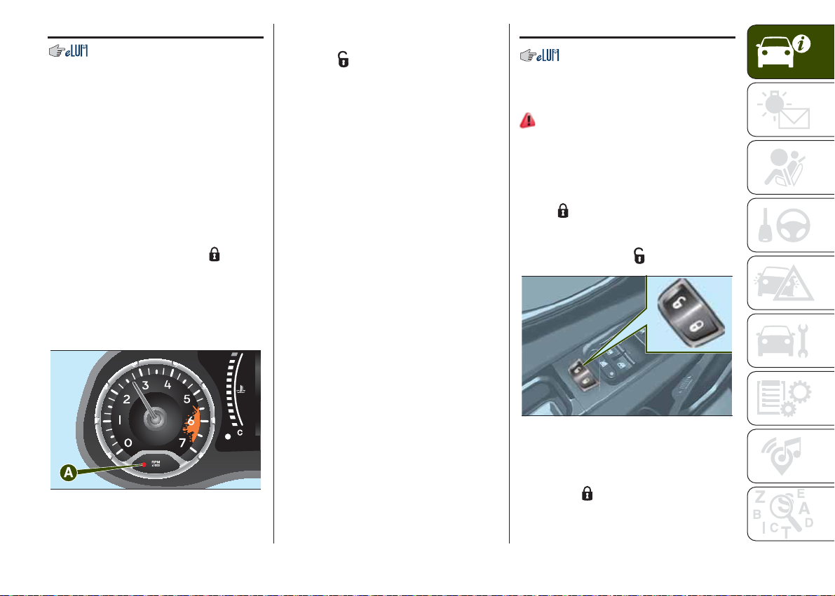
CONTROL PANEL AND ON-BOARD INSTRUMENTS
.
VERSIONS WITH MULTIFUNCTION DISPLAY
38
KNOWING THE INSTRUMENT PANEL
48
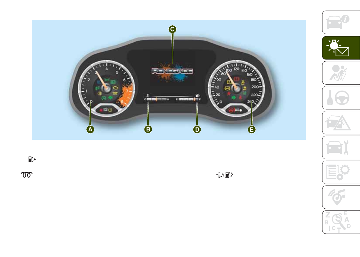
A. Rev counter – B. Digital engine coolant temperature gauge with overheating warning light – C. Multifunction display – D. Digital fuel level gauge
with reserve warning light (the triangle on the right side of the
(speed indicator) (the speedometer contains a brightness sensor)
Warning light supplied on diesel versions only. Diesel versions also contain the icons on the display and the
speedometer full scale is 6000 rpm.
IMPORTANT The illumination of the instrument panel graphics may vary according to version.
symbol indicates the side of the vehicle with the fuel filler) – E. Speedometer
J0A0005C
VERSIONS WITH RECONFIGURABLE MULTIFUNCTION DISPLAY
49
J0A0006C
A. Rev counter – B. Digital engine coolant temperature gauge – C. Multifunction display – D. Digital fuel level gauge (the triangle on the right side of
the
symbol indicates the side of the vehicle with the fuel filler) – E. Speedometer (speed indicator) (the speedometer contains a brightness
sensor)
Warning light supplied on diesel versions only. Diesel versions also contain the icons on the display and the
speedometer full scale is 6000 rpm.
IMPORTANT The illumination of the instrument panel graphics may vary according to version.
39

DISPLAY
MULTIFUNCTION
DISPLAY
The display fig. 50 will show the
following information:
KNOWING THE INSTRUMENT PANEL
❒ Upper part of the display (A): time,
Gear Shift Indicator (where provided),
gear engagement (versions with
automatic transmission), outside
temperature, compass indications,
date.
❒ Central area of the display (B):
vehicle speed, warning messages/any
failure indications.
❒ Lower area of the display (C): total
kilometres (or miles) run and icons of
any failure indications.
RECONFIGURABLE
MULTIFUNCTION
DISPLAY
The display fig. 51 will show the
following information:
12 0
❒ Central area of the display (B):
vehicle speed, warning messages/any
failure indications.
❒ Lower area of the display (C): total
kilometres (or miles) run, digital gauges
for engine coolant temperature and
fuel level
GEAR SHIFT INDICATOR
(where provided)
The Gear Shift Indicator (GSI) system
advises the driver to change gear
through a special indication on the
display. Through the GSI, the driver is
informed that the gear change will allow
a reduction in fuel consumption.
SHIFT UP (
display: suggests switching to a higher
gear.
SHIFT DOWN (
display: suggests switching to a lower
gear.
The indication in the display remains
until a gear is shifted or the driving
conditions go back to a situation where
gearshifting is not required to improve
consumption.
SHIFT) icon on the
SHIFT) icon on the
40
50
J0A2004C
51
❒ Upper area of the display (A):
time, outside temperature, compass
indications, date.
J0A2005C

CONTROL BUTTONS
These are located on the left side of the
steering wheel fig. 52.
52
J0A0189C
They allow the driver to select the items
in the Main menu of the display (see
paragraph "Main menu").
❒
/ : press and release the
buttons to scroll the main menu and the
submenus upwards or downwards.
❒
/ : press and release the
buttons to access the info screens or
the submenus of an item of the main
menu. Button
allows you to exit the
Main menu.
❒ OK: press this button to access/
select the info screens or the submenus
of an item of the main menu. Hold the
button pressed for one second to reset
the displayed/selected functions.
MAIN MENU
Menu items
The Menu includes the following items:
❒ SPEEDOMETER
❒ VEHICLE INFO
❒ DRIVER ASSIST
❒ FUEL ECO
❒ TRIP
❒ STOP/START
❒ AUDIO
❒ ALERTS
❒ DISPLAY SET-UP
❒ VEHICLE SETUP
The Menu item display mode (capital or
lower-case letters) changes according
to the type of display.
Some options have a submenu.
NOTE With the Uconnect™ system,
some Menu items are shown and
managed on the display of the latter
and not on the instrument panel display
(see the paragraphs on the
Uconnect™).
Vehicle setup (Change
vehicle settings)
This function allows you to change the
settings for:
❒ "Display";
❒ "Units";
❒ "Clock & Date";
❒ "Security"
❒ "Safety & Assistance";
❒ "Lights";
❒ "Doors & Locks".
Display
By selecting item "Display" you can
access the settings/information
regarding: "Language", "See phone",
"See navigation".
"Units"
Select item "Units" to choose the unit of
measurement between: "US" (setting
available only for some markets),
"Metric", "Custom".
"Clock & Date"
Select item "Clock & Date" to make the
following adjustments: "Set time",
"Time format", Set date".
"Security"
Select item "Security" to make the
following adjustments: "Passenger
AIRBAG", "Speed beep", "Seat belt
buzzer", "Hill Start Assist".
41

The "Passenger AIRBAG" function is
used to activate/deactivate the front
passenger side airbag. Passenger's
protection active: the LED
comes on constantly on the dashboard
located in the instrument panel.
Passenger's protection not active:
the LED
comes on constantly in the control
panel.
"Safety & Assistance"
For possible adjustments see
paragraph Uconnect™ in chapter
"Multimedia".
"Lights"
Select item "Lights" to make the
following adjustments: "Ambient
lighting", "Follow me", "Headlights while
opening", "Headlight sensor", "High
KNOWING THE INSTRUMENT PANEL
Beams Auto Dim", "Daytime Lights",
"Cornering lights".
"Doors & Locks"
Select item "Doors & Locks" to make
the following adjustments: "Autoclose",
"Auto unlock on exit", "Flash Lights
w/Lock", "Horn with Lock", "Horn
w/Remote Start", "Remote Unlock"
(versions without Passive Entry), "Door
Unlock" (versions with Passive Entry),
"Passive Entry".
OFF on the dashboard
ON
Versions with
reconfigurable multifunction
display
On versions equipped with
reconfigurable multifunction display only
the following items are available:
"Display" (only items "See phone" and
"See navigation" can be selected),
"Security" and "Safety & Assistance"
(only item "Buzzer volume" can be
selected). All other items will be shown
and managed on the Uconnect™
system display.
TRIP COMPUTER
The “Trip computer” is used to display
information on vehicle operation when
the ignition device is at MAR.
This function is characterised by two
separate memories, called "Trip A" and
"Trip B", where the vehicle's "complete
missions" (journeys) are recorded in a
reciprocally independent manner.
“Trip A” allows the following values to
be displayed: "Distance travelled A",
"Average consumption A", "Journey
time (driving time) A".
“Trip B” allows the following values to
be displayed: "Distance travelled B",
"Average consumption B", "Journey
time (driving time) B". The “Trip B”
function may be excluded.
Both memories can be reset: (reset start of a new journey).
To reset the values of "Trip A" and "Trip
B" press and hold the OK button on
the steering wheel controls.
NOTE “Range” and “Instantaneous fuel
consumption" parameters cannot be
reset.
42

WARNING LIGHTS AND MESSAGES
IMPORTANT The warning light switches on in the instrument panel together with a dedicated message and/or acoustic signal
when applicable. These indications are indicative and precautionary and as such must not be considered as exhaustive and/or
alternative to the information contained in the Owner Handbook, which you are advised to read carefully in all cases. Always
refer to the information in this chapter in the event of a failure indication.
IMPORTANT Failure indications displayed are divided into two categories: serious and less serious failures. Serious faults are
indicated by a repeated and prolonged warning "cycle". Less serious faults are indicated by a warning "cycle" with a shorter
duration. The display cycle of both categories can be interrupted. The instrument panel warning light will stay on until the cause
of the failure is eliminated.
WARNING LIGHTS ON INSTRUMENT PANEL
Red warning lights
Warning light What it means
INSUFFICIENT BRAKE FLUID / ELECTRIC PARKING BRAKE ON
Low brake fluid level
The warning light switches on when the brake fluid in the reservoir falls below the minimum level, possibly
due to a leak in the circuit. Restore the brake fluid level, then check that the warning light has switched off.
If the warning light stays on, contact a Jeep Dealership.
Electric parking brake on
The warning light switches on when the electric parking brake is engaged. Release the electric parking
brake, then check that the warning light has switched off. If the warning light stays on, contact a Jeep
Dealership.
43

KNOWING THE INSTRUMENT PANEL
Warning light What it means
EBD FAILURE
The simultaneous switching on of the
indicates either a fault of the EBD system or that the system is not available. In this case, the rear wheels
may suddenly lock and the vehicle may swerve when braking sharply. The display shows the dedicated
message.
Drive very carefully to the nearest Jeep Dealership to have the system inspected immediately.
POWER STEERING FAILURE
If the warning light remains on, you could not have steering assistance and the effort required to operate
the steering wheel could be increased; steering is, however, possible.
On some versions, the display shows the dedicated message.
Contact a Jeep Dealership as soon as possible.
(red) and (amber) warning lights with the engine on
44

Warning light What it means
AIRBAG FAILURE
If the warning light switches on constantly, this indicates a fault in the airbag system. The display shows the
dedicated message.
SEAT BELTS NOT FASTENED
The warning light switches on constantly if the vehicle is stationary and the driver side or passenger side
seat belt, with the passenger seated, is not fastened. The warning light flashes and a buzzer will sound if
the vehicle is in motion and the driver side or passenger side seat belt, with the passenger seated, is not
correctly fastened.
In this case, fasten the seat belt.
28) 29)
WARNING
28) If the warning light does not switch on when the ignition device is moved to MAR or if it stays on when driving (together with the
message on the display), there might be a fault in the restraint systems; in this case, the airbags or pretensioners may not deploy in the event
of an accident or, in a lower number of cases, they could deploy erroneously. Before proceeding, contact a Jeep Dealership to have the
system checked as soon as possible.
29) The fault of the
may not indicate any faults with the restraint systems. Before continuing, contact a Jeep Dealership immediately to have the system checked.
warning light is signalled by the switching on of the icon on the instrument panel. In this case, the warning light
45

KNOWING THE INSTRUMENT PANEL
Warning light What it means
ENGINE COOLANT TEMPERATURE TOO HIGH
The warning light (or the icon on the display) on some versions switches on when the engine is overheated.
The display shows the dedicated message.
When driving normally: stop the vehicle, switch off the engine and check that the water level in the
reservoir is not below the MIN mark. If it is, wait for the engine to cool down, then slowly and carefully open
the cap, top up with coolant and check that the level is between the MIN and MAX marks on the reservoir.
Also check visually for any fluid leaks. If, when restarting, the warning light switches on (or the icon is
displayed) again, contact a Jeep Dealership.
If the vehicle is used under demanding conditions (e.g. in high-performance driving): slow down and,
if the warning light stays on, stop the vehicle. Wait for 2 or 3 minutes with the engine running and slightly
accelerated to further favour the coolant circulation. Then stop the engine. Check the correct coolant level
as described above.
IMPORTANT Over demanding routes, it is advisable to keep the engine on and slightly accelerated for a
few minutes before switching it off.
46

Amber warning lights
Warning light What it means
TPMS SYSTEM
TPMS failure
The warning light switches on when a failure is detected in the TPMS. In this case, contact a Jeep
Dealership as soon as possible. Should one or more wheels be fitted without sensors, the display will show
a warning message until initial conditions are restored.
IMPORTANT Do not continue driving with one or more flat tyres as handling may be compromised. Stop
the vehicle, avoiding sharp braking and steering. Repair immediately using the dedicated tyre repair kit and
contact the dedicated Jeep Dealership as soon as possible.
Tyre pressure low
The warning light switches on and a message is displayed to indicate that the tyre pressure is lower than
the recommended value and/or that slow pressure loss is occurring. In these cases, optimal tyre duration
and fuel consumption may not be guaranteed.
Should two or more tyres be in the condition mentioned above, the display will show the indications
corresponding to each tyre in sequence.
In any situation in which the message on the display is "See manual", it is ESSENTIAL to refer to the
contents of the "Wheels" paragraph in the "Technical data" chapter, strictly complying with the indications
that you find there.
ABS FAILURE
The warning light switches on to indicate an ABS fault. In this case the braking system will work as normal,
but without the extra performance offered by the ABS. The display shows the dedicated message. Drive
carefully and contact a Jeep Dealership as soon as possible.
47

KNOWING THE INSTRUMENT PANEL
Warning light What it means
ESC SYSTEM
ESC system activation
Intervention by the system is indicated by the flashing of the warning light: it indicates that the vehicle is in
critical stability and grip conditions.
ESC system failure
If the warning light does not switch off, or if it stays on with the engine running, a failure was found on the
ESC system. Contact a Jeep Dealership as soon as possible.
Hill Start Assist failure
The warning light switches on and the displays shows the dedicated message, informing about Hill Start
Assist system failure. Contact a Jeep Dealership as soon as possible.
PARTIAL / TOTAL DEACTIVATION OF ACTIVE SAFETY SYSTEMS
The warning light switches on to inform that some active safety systems have been partially or totally
deactivated. When the systems are reactivated, the warning light switches off.
REAR FOG LIGHT
The warning light switches on when the rear fog light is turned on.
FAULT OF THE ELECTRIC PARKING BRAKE
The warning light switches on when a fault about the electric parking brake is detected. The display shows
the dedicated message. Contact a Jeep Dealership as soon as possible.
30)
48
WARNING
30) If a fault is present with sharp braking, the rear wheels may lock and the vehicle may swerve.

Warning light What it means
INJECTION/EOBD SYSTEM FAILURE
If the warning light remains on, or it switches on whilst driving, the injection system is not working properly.
The warning light on constantly signals a malfunction in the supply/ignition system which could cause
high exhaust emissions, a possible loss of performance, poor driveability and high consumption.
On some versions, the display shows the dedicated message.
The warning light switches off if the malfunction disappears, but it is still stored by the system.
Under these conditions, the vehicle can continue travelling at moderate speed but without demanding
excessive effort from the engine or high speed. Prolonged use of the vehicle with the warning light on
constantly may cause damage.
Contact a Jeep Dealership as soon as possible.
If the warning light flashes, it means that the catalytic converter may be damaged. Release the
accelerator pedal to lower the speed of the engine until the warning light stops flashing.
Continue the journey at moderate speed, trying to avoid driving conditions that may cause further flashing
and contact a Jeep Dealership as soon as possible.
14)
WARNING
14) If, turning the ignition device to MAR, the warning light does not turn on or if it turns on steadily or flashing when travelling (on some
versions together with the message on the display), contact a Jeep Dealership as soon as possible.
49

KNOWING THE INSTRUMENT PANEL
Warning light What it means
FUEL RESERVE/LIMITED RANGE
This warning light (or the icon on the display) comes on when about 5 to 7 litres of fuel are left in the tank.
When the remaining range is lower than approx. 50 km (or equivalent value in miles), on some versions, the
display will show a war ning message.
GLOW PLUG PREHEATING FAILURE (Diesel versions)
The warning light will flash (a message will appear on the display, on some versions) to indicate a fault in
the glow plugs preheating system.
In this case, contact a Jeep Dealership as soon as possible.
LANESENSE SYSTEM
Versions with multifunction display
The warning light switches on as follows:
Warning light continuously on (white): the system is activated, but the lane limits were not detected (the
lane lines are grey).
Warning light on and flashing (amber): the vehicle has approached the lane line and is about to pass it.
Warning light switched on continuously (green): the system has detected the limits of both lanes. The
system will act on the steering wheel if the lane was passed unintentionally.
Versions with reconfigurable multifunction display
On versions equipped with reconfigurable multifunction display, the warning light shown at the side is
replaced with dedicated graphic icons, displayed in the upper left area of the display. These icons are
displayed according to the same logic described for versions equipped with multifunction display (see
previous description).
15)
WARNING
50
15) If the warning light (or the icon on the display) flashes whilst driving, contact a Jeep Dealership.

Green warning lights
Warning light What it means
SIDE LIGHTS AND DIPPED BEAM HEADLIGHTS
The warning light switches on when side lights or dipped beam headlights are turned on.
This function allows the headlights to remain on for 30, 60 or 90 seconds after the ignition device was
placed in STOP position ("Follow me" function).
AUTOMATIC MAIN BEAM HEADLIGHTS
This warning light comes on when the automatic main beam headlights turned on.
FOG LIGHTS
The warning light switches on when the fog lights are turned on.
LEFT-HAND DIRECTION INDICATOR
The warning light switches on when the direction indicator control stalk is moved downwards or, together
with the right indicator, when the hazard warning light button is pressed.
RIGHT-HAND DIRECTION INDICATOR
The warning light switches on when the direction indicator control stalk is moved upwards or, together with
the left indicator, when the hazard warning light button is pressed.
STOP/START SYSTEM INTERVENTION
The warning light comes on in the event of Stop/Start system intervention (engine switching off). Restarting
the engine, the warning light switches off.
51

Blue warning lights
Warning light What it means
SYMBOLS ON THE DISPLAY
Red symbols on the display
Symbol What it means
KNOWING THE INSTRUMENT PANEL
MAIN BEAM HEADLIGHTS
The warning light switches on when the main beam headlights are turned on.
LOW ENGINE OIL PRESSURE
The symbol switches on, together with a message on the display, if there is insufficient engine oil pressure.
16)
IMPORTANT Do not use the vehicle until the failure has been solved. The switching on of the symbol does
not show the quantity of oil in the engine: the oil level must be checked manually.
AIRBAG FAILURE
If the symbol switches on constantly, this indicates a failure in the airbag system. The display shows the
dedicated message. Contact a Jeep Dealership as soon as possible.
ALTERNATOR FAILURE
The switching on of the symbol with engine on corresponds to an alternator failure. Contact a Jeep
Dealership as soon as possible.
52
WARNING
16) If the symbol switches on when driving, stop the engine immediately and contact a Jeep Dealership.

Symbol What it means
INCOMPLETE DOOR LOCKING
The symbol switches on when one or more doors are not completely shut. An acoustic signal is activated
with the doors open and the vehicle moving. Close the doors properly.
BONNET NOT PROPERLY SHUT
The symbol switches on when the bonnet is not properly shut. A buzzer is heard when the bonnet is open
and the vehicle is moving. Close the bonnet properly.
TAILGATE NOT PROPERLY SHUT
The symbol switches on when the tailgate is not properly shut. A buzzer is heard with open tailgate and
vehicle moving. Close the tailgate correctly.
AUTOMATIC TRANSMISSION FAILURE
The symbol switches on (together with a message in the display and a buzzer) to indicate that the
automatic transmission is faulty. Contact a Jeep Dealership as soon as possible.
EXCESSIVE ENGINE OIL TEMPERATURE
The symbol switches on in the case of engine oil overheating.
18)
17)
WARNING
17) Driving the vehicle with this symbol on may severely damage the gearbox, with resulting breakage. The oil may also overheat: contact
with hot engine or with exhaust components at high temperature could cause fires.
WARNING
18) If the symbol switches on when driving, stop the vehicle and the engine immediately.
53

Amber symbols on the display
Symbol What it means
KNOWING THE INSTRUMENT PANEL
SENTRY KEY FAILURE / BREAK-IN ATTEMPT
Sentry Key system failure
The symbol switches on to report a failure of the Sentry Key system. Contact a Jeep Dealership as soon as
possible.
Break-in attempt
The symbol switches on when the ignition device is moved to MAR position, along with the displaying of a
dedicated message, to report about a possible break-in attempt detected by the alarm system.
FUEL CUT-OFF SYSTEM OPERATION
The symbol switches on (along with a message on the display) in the event of fuel cut-off system
intervention.
For reactivating the fuel cut-off system, refer to the description in section "Fuel cut-off system" in chapter
"In an emergency". If it is still not possible to restore the fuel supply, contact a Jeep Dealership.
POSSIBLE ICE ON ROAD
The symbol switches on (along with a dedicated message on the display) when the outdoor temperature is
lower or equal to 3°C.
IMPORTANT In the event of outside temperature sensor failure, the digits that indicate the value are
replaced by dashes.
ENGINE OIL PRESSURE SENSOR FAILURE
The symbol switches on constantly together with the message in the display in case of engine oil pressure
sensor failure.
54

Symbol What it means
FORWARD COLLISION WARNING PLUS SYSTEM FAILURE
The symbols switch on (with the displayed message) in the case of failure of the Forward Collision Warning
Plus system. Contact a Jeep Dealership as soon as possible.
FORWARD COLLISION WARNING PLUS SYSTEM DEACTIVATION
The symbol (or the war ning light on the dashboard) switches on if the Forward Collision Warning Plus
system has been deactivated.
RAIN SENSOR FAILURE
The symbol switches on (along with a message on the display) in the event of rain sensor failure. Contact a
Jeep Dealership as soon as possible.
STOP/START SYSTEM FAILURE
The symbol switches on to report a failure of the Stop/Start system. The display will show a dedicated
message. Contact a Jeep Dealership as soon as possible.
KEYLESS ENTER-N-GO SYSTEM FAILURE
The symbol switches on, along with a displayed message, in case of Keyless Enter-N-Go system failure.
Contact a Jeep Dealership as soon as possible.
FUEL CUT-OFF SYSTEM FAILURE
The symbol switches on along with a message on the display in the event of fuel cut-off system failure.
Contact a Jeep Dealership as soon as possible.
SPEED LIMITER FAILURE
The symbol switches on in case of failure of the Speed Limiter device. Contact a Jeep Dealership to have
the failure solved.
55

KNOWING THE INSTRUMENT PANEL
Symbol What it means
LANESENSE SYSTEM FAILURE
Camera obstructed: the symbol lights up in the case of dirt on the windscreen, which may adversely
affect correct operation of the camera. On versions equipped with reconfigurable multifunction display the
vehicle icon is shown in the upper right area of the display. In this case clean the windscreen using a soft
clean cloth, taking care not to scratch it. Should the failure persist, contact a Jeep Dealership as soon as
possible.
LaneSense system failure: the symbol also lights up in the case of failure to the LaneSense system. In
this case contact a Jeep Dealership as soon as possible.
AUTOMATIC MAIN BEAM HEADLIGHTS FAILURE
The symbol switches on to report a failure of the automatic main beam headlights. Contact a Jeep
Dealership as soon as possible.
Symbol What it means
AUTOMATIC TRANSMISSION FLUID OVERHEATING
The symbol switches on in the case of transmission overheating, after a particularly demanding use. In this
case an engine performance limitation is carried out. With engine off or at idle speed, wait until the symbol
switches off.
TOW HOOK FAILURE
The symbol switches on to report a failure of the tow hook. Contact a Jeep Dealership as soon as
possible.
AUDIO SYSTEM FAILURE
The symbol switches on to report a failure of the audio system. Contact a Jeep Dealership as soon as
possible.
56

Symbol What it means
DUSK SENSOR FAILURE
The symbol switches on along with a message on the display in the event of dusk sensor failure. Contact a
Jeep Dealership as soon as possible.
WATER IN DIESEL FILTER (diesel versions)
The symbol switches on constantly when driving (along with a message in the display), to indicate the
presence of water in the diesel filter.
19)
WARNING
19) The presence of water in the fuel supply system circuit may cause severe damage to the injection system and irregular engine operation.
If the
the above indications come on immediately after refuelling, water has probably been poured into the tank: switch the engine off immediately
and contact a Jeep Dealership.
symbol is displayed (along with a message in the display) contact a Jeep Dealership as soon as possible to bleed the system. If
57

Symbol What it means
ENGINE OIL DETERIORATED
(where provided)
Diesel versions: the symbol is displayed on some versions, along with a dedicated message displaying.
The symbol is displayed for 3 minute cycles and intervals of 5 seconds until oil is changed.
The symbol is displayed until the problem is solved.
Petrol versions: the symbol switches on and then is not displayed when the display cycle is completed.
IMPORTANT After the first indication, each time the engine is started the symbol will continue to switch on
as described above until the oil is changed. On certain versions a dedicated message is displayed.
If the symbol flashes, this does not mean that there is a fault on the vehicle, rather it simply reports that it is
now necessary to change the oil as a result of regular use of the vehicle.
The deterioration of engine oil is accelerated by using the vehicle for short drives, preventing the engine
from reaching operating temperature.
Contact a Jeep Dealership as soon as possible.
20) 21)
WARNING
KNOWING THE INSTRUMENT PANEL
20) Deteriorated engine oil should be replaced as soon as possible after the symbol is switched on, and never more than 500 km after it first
switches on. Failure to observe the above indications may result in severe damage to the engine and invalidate the warranty. The switching
on of this symbol is not correlated to the quantity of oil in the engine, therefore if it flashes you do not need to top up the engine oil.
21) If the symbol flashes whilst driving, contact a Jeep Dealership.
58

Symbol What it means
EXTERIOR LIGHTS FAILURE
the symbol switches on to indicate a failure on the following lights: daytime running lights (DRLs); parking
lights; trailer direction indicators (if present); trailer lights (if present); side lights; direction indicators; fog
light; reversing light; brake lights; number plate lights.
The failure may be caused by a blown bulb, a blown protection fuse or an interruption of the electrical
connection.
DPF CLEANING (particulate trap) in progress (diesel versions with DPF only)
The symbol switches on constantly to indicate that the DPF system needs to eliminate the trapped
pollutants (particulate) through the regeneration process.
The symbol does not switch on during every DPF regeneration, but only when driving conditions require
that the driver is notified. To turn off the symbol, keep the vehicle in motion until the regeneration process is
over. On average, the process lasts 15 minutes. Optimal conditions for completing the process are
achieved by travelling at 60 km/h with engine speed above 2000 rpm.
When this symbol switches on, it does not indicate a vehicle failure and thus it should not be taken to a
workshop. On some versions, together with the symbol switching on, the display shows a dedicated
message.
22)
WARNING
22) Vehicle travel speed should always be adapted to the traffic and weather conditions, and must always comply with traffic regulations. The
engine can be stopped even if the DPF warning light is on: however, repeated interruptions of the regeneration process could cause
premature deterioration of the engine oil. For this reason it is always advisable to wait for the symbol to go off before turning off the engine,
following the instructions above. It is not advisable to complete DPF regeneration with the vehicle stationary.
59

White symbols
KNOWING THE INSTRUMENT PANEL
Symbol What it means What to do
SPEED LIMIT EXCEEDED
The symbol switches on when the set speed limit (e.g.
120 km/h / 75 mph) is exceeded; this can be done
through the menu of the display.
On some versions a message is displayed and an
acoustic signal is emitted.
Note For specific versions/markets another red symbol comes on as well.
HILL DESCENT CONTROL
(where provided)
Symbol on constantly: Hill Descent Control system
activation.
Symbol flashing: Hill Descent Control system
deactivation.
ELECTRONIC CRUISE CONTROL
The symbol switches on if the electronic Cruise Control
is activated.
SPEED LIMITER
The symbol switches on if the Speed Limiter device is
activated.
60

Messages on the display
Message on the display
SERV 4WD
BLIND-SPOT MONITORING
PARKSENSE
FOUR WHEEL DRIVE FAILURE
This indicator switches on to report a four wheel drive system failure. Contact a Jeep
Dealership as soon as possible.
BLIND-SPOT MONITORING SYSTEM
Sensor locking: a dedicated message is displayed in the case of failure of the Blind-spot
Monitoring system sensor. In this case, the LEDs on the door mirrors are switched on
constantly. An acoustic signal is also issued.
Free the bumper of any obstacles, cleaning it.
System not available: a dedicated message is displayed if the Blind-spot Monitoring
system is not available. In this case, the LEDs on the door mirrors are switched on
constantly.
The failed operation of the system might be due to the insufficient voltage from the battery
or other failures on the electrical system. Contact a Jeep Dealership as soon as possible
to have the electrical system checked.
PARKSENSE SYSTEM
(where provided)
Sensor locking: the message is displayed in the case of a failure of the ParkSense
system sensors. An acoustic signal is also issued.
Free the bumper of any obstacles, cleaning it.
System not available: a dedicated message is displayed if the Parksense system is not
available.
The failed operation of the system might be due to the insufficient voltage from the battery
or other failures on the electrical system. Contact a Jeep Dealership as soon as possible
to have the electrical system checked.
61

KNOWING THE INSTRUMENT PANEL
Message on the display
"SERVICE" MESSAGE (SCHEDULED
SERVICING)
SCHEDULED SERVICING (SERVICE)
When the following scheduled servicing is approaching ("coupon"), the word "Service" will
be displayed, followed by the number of kilometres/miles or days (where provided) left,
when the ignition device is turned to MAR.
Contact a Jeep Dealership. The operations of the "Scheduled Servicing Plan" will be
performed and the message will be reset.
62

SAFETY
The chapter that you are about to read
is very important: it describes the
safety systems with which the vehicle is
equipped and provides instructions on
how to use them correctly.
ACTIVE SAFETY SYSTEMS ............ 64
AUXILIARY DRIVING SYSTEMS ...... 69
-BSM (Blind Spot Monitoring)
SYSTEM.............................................. 69
-FORWARD COLLISION WARNING
PLUS SYSTEM.................................... 71
-TPMS (Tyre Pressure Monitoring
System) ............................................... 73
OCCUPANT PROTECTION
SYSTEMS ....................................... 76
SEAT BELTS ................................... 76
SBR (SEAT BELT REMINDER)
SYSTEM ......................................... 77
PRETENSIONERS........................... 79
CHILD PROTECTION SYSTEMS ..... 81
SUPPLEMENTARY RESTRAINT
SYSTEM (SRS) - AIRBAG................ 91
63

ACTIVE SAFETY
SYSTEMS
ABS (Anti-lock Braking
System)
SAFETY
This system, which is an integral part of
the braking system, prevents one or
more wheels from locking and slipping
in all road surface conditions,
irrespective of the intensity of the
braking action, ensuring that the vehicle
can be controlled even during
emergency braking and optimising
stopping distances.
System intervention
The driver can feel that the ABS system
has come into action because the
brake pedal pulsates slightly and the
system gets noisier: this is entirely
normal with the system operating.
31) 32) 33) 34) 35) 36) 37)
DTC (Drag Torque
Control) SYSTEM
The system intervenes in the event of
sudden downshifting, or during ABS
braking, restoring torque to the engine
and thus preventing excessive drag
at the drive wheels, which may lead the
wheels to lock and a loss of vehicle
stability, above all in low-grip
conditions.
ESC (Electronic Stability
Control) SYSTEM
The ESC system improves the
directional control and stability of the
vehicle in various driving conditions,
correcting understeer and oversteer,
distributing the brake force on the
appropriate wheels.
System intervention
The intervention of the system is
indicated by the flashing of the
warning light on the instrument
panel, to inform the driver that
the vehicle is in critical stability and grip
conditions.
38) 39) 40) 41) 42)
TC (Traction Control)
SYSTEM
The system automatically operates in
the event of slipping, loss of grip on wet
roads (aquaplaning) and acceleration
on slippery, snowy or icy roads, etc. on
one or both drive wheels.
System intervention
The intervention of the system is
indicated by the flashing of the
warning light on the instrument
panel, to inform the driver that
the vehicle is in critical stability and grip
conditions.
43) 44) 45) 46) 47)
PBA (Panic Brake
Assist) SYSTEM
The PBA system is designed to
improve the vehicle’s braking capacity
during emergency braking.
The brake pedal should be pressed
continuously during braking, avoiding
intermittent presses, to get the most
out of the system. Do not reduce
pressure on the brake pedal until
braking is not necessary anymore.
The PBA system is deactivated when
the brake pedal is released.
48) 49) 50)
HSA (Hill Start Assist)
SYSTEM
This system is an integral part of the
ESC system and facilitates starting on
slopes.
System deactivation
The Hill Start Assist system can be
deactivated using the display Menu
(see the instructions in the "Display"
paragraph, "Knowing the instrument
panel" chapter).
51) 52)
64

DST SYSTEM (Dynamic
Steering Torque)
The DST function uses the integration
of the ESC system with the electric
power steering to increase the safety
level of the whole vehicle.
53)
ERM (Electronic Rollover
Mitigation) SYSTEM
The system monitors the tendency of
the wheels to rise from the ground if the
driver performs extreme manoeuvres
like quick steering to avoid an obstacle,
especially in poor road conditions.
If these conditions occur, the system
intervenes on the brakes and engine
power to reduce the possibility that the
wheels are raised from the ground. It
is not possible to avoid tendency to roll
over if the phenomenon is due to
reasons such as driving on high side
gradients, collision with objects or other
vehicles.
54)
TSC (Trailer Sway
Control) SYSTEM
The system employs a series of
sensors located on the vehicle to
identify excessive swerving of the trailer
and take the necessary precautions
to eliminate it.
System intervention
When the system is active, the
warning light flashes on the
instrument panel, the engine power is
reduced and braking can be felt on the
individual wheels, following the attempt
to eliminate the swerving of the trailer.
The system is active only with ESC
engaged.
When the ESC system is deactivated
(by pressing the button on the central
tunnel), the TSC system is deactivated
as well.
55) 56)
HDC (Hill Descent
Control) SYSTEM
(where provided)
It is an integral part of the ESC system
and is aimed at keeping the vehicle at a
constant speed during a descent,
operating autonomously on the brakes
in various ways at the same time.
In this way the vehicle stability and
completely safe driving are guaranteed,
above all in poor grip conditions and
steep descents.
Enabling the system
To enable the system, press the button
fig. 53:
The system is enabled if the following
conditions are met:
53
J0A0154C
❒ the Selec-Terrain™ device is in
4WD LOW mode;
❒ the vehicle speed is below 25 km/h;
❒ the electric parking brake (EPB) is
deactivated;
❒ the driver side door is closed.
Activation of the system
Once enabled, the HDC system will
activate automatically if the vehicle
is driven downhill on a steep slope,
higher than 8%.
The speed set for the HDC system can
be adjusted using the brake pedal
and the accelerator pedal (in the
1–25 km/h range). Once the desired
speed is reached, when both pedals
are released the HDC system will
maintain the set speed.
In this way, the driver can adjust the
speed and, if necessary, reassume
control of the vehicle.
65

With gear lever in neutral, speed
adjustment using the accelerator pedal
is not available.
The driver can cancel the intervention of
SAFETY
the HDC system at any time by
completely depressing the accelerator
pedal or the brake pedal.
System deactivation
The HDC system is deactivated, but
remains available, if one of the following
conditions is met:
❒ the speed of the vehicle exceeds
25 km/h but remains below 40 km/h;
❒ the vehicle is on a descent with
insufficient gradient, below 8%, or a
level surface, or is going uphill;
❒ the gear lever is in P (Park) position.
Disabling the system
The system is deactivated and disabled
if one of the following conditions is
met:
❒ button press fig. 53;
❒ activation of mode other than 4WD
LOW;
❒ electric parking brake (EPB)
engagement;
❒ driver side door open;
❒ speed of 40 km/h exceeded
(immediate exit from HDC function).
57) 58)
DISABLING ACTIVE
SAFETY SYSTEMS
Depending on the versions, there are 3
configurations for the active safety
systems on the vehicle:
❒ systems enabled;
❒ systems partially disabled;
❒ systems disabled.
Systems enabled
All active safety systems are enabled.
This is the normal operating mode
when driving a four-wheel-drive vehicle.
This mode should be used in most
driving conditions. The system will be in
"Systems enabled" mode every time
the engine is started.
IMPORTANT You are advised to select
"Systems partially disabled" or
"Systems disabled" modes only for
specific driving requirements.
Systems partially disabled
By pressing the
button on the central
tunnel fig. 54 for fewer than 5 seconds
when driving, the TSC system can
be disabled and the intervention of the
TC system can be limited to braking
action on the individual drive wheels.
The other systems remain enabled.
Activation of this mode is indicated by
the
warning light on the instrument
panel switching on (on some versions,
together with a message on the
display).
54
J0A0282C
To restore "All systems enabled"
operating mode, press the button on
the central tunnel again.
"Systems completely enabled" mode
will automatically reactivate every time
the engine is started.
IMPORTANT When travelling on snowy
roads with snow chains, it may be
helpful to activate "Systems partially
disabled" mode: in these conditions,
slipping of the drive wheels when
moving off makes it possible to obtain
better traction.
66

Systems disabled
Pressing the
button on the central
tunnel for more than 5 seconds
completely deactivates the ESC
system, as well as the TSC and ERM
systems; the TC system will be limited
to braking action on the individual
drive wheels. The other systems remain
enabled.
Activation of this mode is highlighted by
the
warning light on the instrument
panel switching on (on some versions,
together with a message on the
display).
IMPORTANT If a speed of
approximately 65 km/h (40 mph) is
exceeded, the systems will behave as
described for "Systems partially
disabled" mode.
To restore "Systems enabled" operating
mode, press the button on the central
tunnel again.
"Systems enabled" mode will
automatically reactivate every time the
engine is started.
Versions with Selec-Terrain™
device
On versions with Selec-Terrain™
device, the activation of certain driving
modes partially or totally deactivates
certain active safety systems in order to
optimise performance in the specific
mode.
When active safety systems are partially
or totally deactivated, the
warning
light will turn on in the instrument panel.
In "SAND" and "MUD" modes, the
active safety systems are partially
disabled and fine-tuned to ensure
maximum performance in the specific
operating modes. It is in any case
possible to reactivate them completely
at any time by pressing the
button on
the central tunnel should you wish to
favour safety over "off-road"
performance.
IMPORTANT In 4WD LOW modes, the
active safety systems are completely
disabled in order to ensure maximum
off-road driving performance and it will
not be possible to reactivate them.
59) 60) 61) 62)
WARNING
31) When the ABS intervenes and you feel
the brake pedal pulsating, do not reduce
the pressure, but hold it down firmly and
confidently; in doing so you will brake
in the shortest distance possible,
depending on the current road conditions.
32) For maximum efficiency of the braking
system, a bedding-in period of about
500 km is required: during this period it is
advisable to avoid sharp, repeated and
prolonged braking.
33) If the ABS intervenes, this indicates
that the grip of the tyres on the road is
nearing its limit: you must slow down to a
speed compatible with the available grip.
34) The ABS can’t overrule the natural laws
of physics, and can’t increase the grip
available according to the condition of the
road.
35) The ABS cannot prevent accidents,
including those due to excessive speed on
corners, driving on low-grip surfaces or
aquaplaning.
36) The capability of the ABS must never
be tested irresponsibly and dangerously, in
such a way as to compromise personal
safety and the safety of others.
37) For the correct operation of the ABS,
the tyres must of necessity be the same
make and type on all wheels, in perfect
condition and, above all, of the prescribed
type and size.
38) The ESC system cannot alter the
natural laws of physics, and cannot
increase grip, which depends on the
condition of the road.
39) The ESC system cannot prevent
accidents, including those due to excessive
speed on corners, driving on low-grip
surfaces or aquaplaning.
40) The capability of the ESC system must
never be tested irresponsibly and
dangerously, in such a way as to
compromise personal safety and the safety
of others.
41) For the correct operation of the ESC
system, the tyres must of necessity be the
same make and type on all wheels, in
perfect condition and, above all, of the
prescribed type and size.
67

42) ESC performance features must not
induce the driver to take unnecessary
or unfounded risks. Your driving style must
always be suited to the road conditions,
visibility and traffic. The driver is, in any
SAFETY
case, responsible for safe driving.
43) For the correct operation of the TC
system, the tyres must of necessity be the
same make and type on all wheels, in
perfect condition and, above all, of the
prescribed type and size.
44) TC performance features must not
induce the driver to take unnecessary or
unfounded risks. Your driving style must
always be suited to the road conditions,
visibility and traffic. The driver is, in any
case, responsible for safe driving.
45) The TC system can’t overrule the
natural laws of physics, and can’t increase
the grip available according to the
condition of the road.
46) The TC system cannot prevent
accidents, including those due to excessive
speed on corners, driving on low-grip
surfaces or aquaplaning.
47) The capability of the TC must never be
tested irresponsibly and dangerously, in
such a way as to compromise personal
safety and the safety of others.
48) The PBA system can’t overrule the
natural laws of physics, and can’t increase
the grip available according to the
condition of the road.
49) The PBA system cannot prevent
accidents, including those due to excessive
speed on corners, driving on low-grip
surfaces or aquaplaning.
50) The capability of the PBA system must
never be tested irresponsibly and
dangerously, in such a way as to
compromise the safety of the driver, the
other occupants of the vehicle or any other
road user.
51) The Hill Start Assist system is not a
parking brake; therefore, never leave the
vehicle without having engaged the electric
parking brake, turned the engine off and
engaged first gear, so that it is parked
in safe conditions (for further information
read the "Parking" paragraph in the
"Starting and driving" chapter).
52) There may be situations on small
gradients (less than 8%), with vehicle
laden, in which the Hill Start Assist system
may not activate, causing a slight reversing
motion and increasing the risk of collision
with another vehicle or object. The driver is,
in any case, responsible for safe driving.
53) DST is an aid for driving and does not
relieve the driver of responsibility for driving
the vehicle.
54) The performance of a vehicle with ERM
must never be tested in imprudent or
dangerous ways, with the possibility of
putting the safety of the driver or other
people at risk.
55) When towing trailers, the utmost
caution at the wheel is advised. Never
exceed the maximum permitted loads (see
the description in the "Weights" paragraph
in the "Technical Specifications" chapter).
56) The TSC system cannot prevent
swerving for all trailers. If the system
activates during driving, reduce the speed,
stop the vehicle in a safe place and arrange
the load correctly to prevent the trailer
from swerving.
57) Prolonged use of the system may
overheat the braking system. If the brakes
overheat, the HDC system, when active,
will be gradually deactivated after suitably
informing the driver (LED on button off):
it can be reactivated only when the brakes
have cooled sufficiently. The distance
that can be covered depends on the
temperature of the brakes and therefore on
the gradient, load and speed of the
vehicle.
58) The performance of a vehicle with HDC
must never be tested in imprudent or
dangerous ways, with the possibility of
putting the safety of the driver or other
people at risk.
59) When "Systems partially disabled"
mode is selected, the intervention of the
TC function is limited to braking action on
the individual drive wheels and the
warning lights switches on in the
instrument panel. In "systems partially
disabled" mode, the engine torque value
that the ESC system may require will
not be guaranteed and the stability of the
vehicle will therefore be reduced.
60) With "Systems partially disabled" mode
selected, the TSC (Trailer Sway Control)
system is disabled.
61) Your driving style must always be
suited to the road conditions, visibility and
traffic. The driver is, in any case,
responsible for safe driving.
68

62) When "Systems disabled" mode is
selected, the ESC system will not be
available in the event of emergency
manoeuvres. "Systems disabled" mode is
only for off-road use.
AUXILIARY DRIVING
SYSTEMS
BSM (Blind Spot
Monitoring) SYSTEM
(where provided)
The system uses two radar sensors,
located in the rear bumper (one for
each side - see fig. 55), to detect the
presence of vehicles (vehicles, trucks,
motorbikes, etc.) in the rear side blind
spots of your vehicle.
55
J0A0220C
The system warns the driver about the
presence of vehicles in the detection
area by lighting up, on the relevant side,
the warning light located on the door
mirror fig. 56, along with an acoustic
warning. When the vehicle is started the
warning light turns on to signal the
driver that the system is active.
56
J0A0217C
Sensors
The sensors are activated engaging any
forward gear at a speed higher than
about 10 km/h, or engaging the reverse
gear.
The sensors are temporarily
deactivated with vehicle at a standstill
and the gear lever in position P (Park)
(versions with automatic transmission),
or with vehicle at a standstill and
electric parking brake engaged
(versions with manual gearbox).
69

The detection area of the system
covers about a lane on both sides of
the vehicle (around 3 metres). This area
begins from the door mirror and
SAFETY
extends for about 6 metres towards the
rear part of the vehicle.
When the sensors are active the system
monitors the detection areas on both
sides of the vehicle and warns the
driver about the possible presence of
vehicles in these areas.
While driving the system monitors the
detection area from three different input
points (side, rear and front) to check
whether a signal needs to be sent
to the driver. The system can detect the
presence of a vehicle in one of these
three areas.
Important
63)
The system does not signal the
presence of fixed object (e.g. safety
barriers, poles, walls, etc.). However, in
some circumstances, the system may
activate in the presence of these
objects. This is normal and does not
indicate a system malfunction.
The system does not warn the driver
about the presence of vehicles coming
from the opposite direction, in the
adjacent lanes.
If a trailer is hitched to the vehicle, the
system automatically deactivates.
The rear bumper area where the radar
sensors are located must stay free from
snow, ice and dirt gathered from the
road surface for the system to operate
correctly.
Do not cover the rear bumper area
where the radar sensors are located
with any object (e.g. adhesives, bike
rack, etc.).
Rear view: the system detects vehicles
approaching to the rear part of your
vehicle on both sides and entering the
rear detection area with a speed delta
lower than 50 km/h with respect to your
vehicle.
Overtaking vehicles: if another vehicle
is overtaken slowly (with a speed delta
lower than about 25 km/h) and this
stays in the blind spot for about 1.5
seconds, the warning light on the door
mirror of the corresponding side lights
up. If the speed delta between the
two vehicles is higher than about 25
km/h, the warning light does not light
up.
RCP (Rear Cross Path
detection) system
This system helps the driver during
reverse manoeuvres in the case of
reduced visibility. During "RCP"
operating mode, the system emits
acoustic and visual warnings if
the presence of an object is detected.
When an acoustic warning is sent,
the Uconnect™ volume is lowered.
The system can be activated/
deactivated through the display Menu
or the Uconnect™ system.
The system monitors the rear detection
areas on both sides of the vehicle, to
detect objects moving towards the
sides of the vehicle at a minimum
speed comprised between about 1
km/h and 3 km/h and objects moving
at a maximum speed of 35 km/h, as
generally happens in the parking areas.
The system activation is signalled to
the driver by means of a visual and
acoustic warning.
IMPORTANT If the sensors are covered
by objects or vehicles, the system will
not warn the driver.
70

"Blind spot alert", "Visual" mode:
when this mode is active, the BSM
system sends a visual warning to the
relevant door mirror, according to
the detected object. When operating in
RCP mode, the system sends visual
and acoustic warnings when the
presence of an approaching object is
detected. When an acoustic warning is
sent, the Uconnect™ volume is
lowered.
"Blind spot alert", "Visual &
acoustic" mode: when this mode is
active, the BSM system sends a visual
warning to the relevant door mirror,
according to the detected object. If the
direction indicator on the side where
an obstacle has been detected is
activated, an acoustic warning is
emitted as well. When the acoustic
warning is emitted, the Uconnect™
volume is lowered.
"Blind spot alert" function
deactivation: when the system is
deactivated ("Blind spot alert" mode at
"OFF"), the BSM or RCP systems will
not emit neither acoustic nor visual
warnings. The BSM system will store
the operating mode running when
the engine was switched off: each time
the engine is started, the operating
mode stored previously will be recalled
and used.
FORWARD COLLISION
WARNING PLUS SYSTEM
64) 65) 66) 67)
23) 24) 25) 26) 27) 28) 29) 30) 31)
It comprises a radar located behind the
front bumper fig. 57 and a camera
located in the central part of the
windscreen fig. 58.
57
J0A0334C
In the event of an imminent collision the
system intervenes by automatically
braking the vehicle to prevent the crash
or reduce its effects.
58
J0A0241C
The system may lightly brake to warn
the driver if a possible frontal accident
is detected. Signals and limited braking
are intended to allow the driver to
react promptly, in order to prevent or
reduce the effects of a potential
accident.
Versions equipped with Stop/Start
system: at the end of the automatic
braking, the Stop/Start system will
activate as described in paragraph
"Stop/Start system" of this chapter.
Versions equipped with manual
gearbox: at the end of the automatic
braking the engine may stall and turn
off, unless the clutch pedal is pressed.
Versions equipped with automatic
transmission: at the end of the
braking, the latest stored gear
is engaged: the vehicle may restart after
a few seconds from the automatic
stop.
IMPORTANT After the vehicle is
stopped, the brake calipers may be
locked for about 2 seconds for safety
reasons. Make sure you press the
brake pedal if the vehicle moves slightly
forwards.
71

SAFETY
72
Activation/deactivation
The Forward Collision Warning Plus
system can be deactivated (and then
reactivated) via the Uconnect™
system. The system can also
be deactivated bringing the ignition
device to MAR.
IMPORTANT The system status can be
changed with vehicle at a standstill
only.
Activation/deactivation
If the Forward Collision Warning Plus
system has been correctly activated
with the Uconnect™ system, this will
be active each time the engine is
started.
To deactivate the system, hold the
button on the central tunnel pressed.
Following a deactivation, the system
will not warn the driver about the
possible collision with the preceding
vehicle, regardless of the setting
selected with the Uconnect™ system.
To reactivate the system press the
button again.
The system only works if:
❒ it is activated via the Uconnect™
system;
❒ it has not been deactivated with a
long press of the
button;
❒ the ignition device is at MAR;
❒ the vehicle speed is between 7 and
200 km/h;
❒ the front seat belts are fastened.
System limited operation
signal
If the dedicated message is displayed,
a condition limiting the system
operation may have occurred. The
possible reasons of this limitation are
something blocking the camera view or
a fault. If an obstruction is signalled,
clean the area of the windscreen
indicated in fig. 58 and check that the
message has disappeared.
In this case the system might be not
completely available.
When the conditions limiting the system
functions end, this will go back to a
normal and complete operation. Should
the fault persist, contact a Jeep
Dealership.
Driving in special conditions
In certain driving conditions, such as,
for example:
❒ driving close to a bend (see fig. 59);
❒ vehicles with small dimensions
and/or not aligned in the driving lane
(see fig. 60);
❒ lane change by other vehicles (see
fig. 61);
❒ vehicle driving in a transverse way
(see fig. 62);
system intervention might be
unexpected or delayed. The driver must
be very careful, keeping control of the
vehicle to drive in complete safety.
59
60
J0A0081C
J0A0082C

61
62
J0A0083C
J0A0336C
Important
❒ The system has not been designed
to prevent impacts and cannot detect
possible conditions leading to an
accident in advance. Failure to take into
account this warning may lead to
serious or fatal injuries.
❒ The system may activate, assessing
the trajectory of the vehicle, for the
presence of reflecting metal objects
different from other vehicles, such as
safety barriers, road signs, barriers
before parking areas, tollgates, level
crossings, gates, railways, objects near
road constructions sites or higher
than the vehicle (e.g. a flyover). In the
same way, the system may intervene
inside multi-storey car parks or
galleries, or due to a glare on the road
surface. These possible activations
follow the normal operating logic of the
system and must not be regarded as
faults.
❒ The system has been designed for
road use only. If the vehicle is driven
off-road, the system must be
deactivated, to avoid unnecessary
warnings. By selecting the 4WD LOW
mode, the system is automatically
deactivated. Automatic deactivation is
signalled by the dedicated warning
light/icon switching on in the instrument
panel.
TPMS (Tyre Pressure
Monitoring System)
(where provided)
68) 69) 70) 71) 72) 73) 74) 32)
The TPMS (Tyre Pressure Monitoring
System) signals possible insufficient tyre
pressure according to the cold
pressure indicated in chapter "Technical
specifications".
The system comprises a radiofrequency transmitter sensor fitted to
each wheel (on the rim inside the tyre),
which is able to send information on the
inflation pressure of each tyre to the
control unit.
The system automatically updates and
warning light
switches off each
time the system receives the updated
inflation pressures. The vehicle might
need to be driven at a speed higher
than about 25 km/h (15 mph) up to 20
minutes for the TPMS to receive this
information.
73

IMPORTANT The TPMS is designed for
original tyres and wheels. Pressure
and alarms signalled by the TPMS are
defined according to the size of the
SAFETY
tyres fitted on the vehicle. Using spare
wheels of a size, type and/or design
different from the original ones may
cause an irregular operation of the
system and damage the sensors.
Aftermarket fitted wheels may damage
the sensors. Using aftermarket tyre
sealants may damage the Tyre Pressure
Monitoring System sensor. If
aftermarket tyre sealant is used it is
recommended to go to a Jeep
Dealership to have the sensors
checked. After tyre pressure check and
adjustment, always refit the valve plug
to prevent humidity and dirt from
entering, these may damage the Tyre
Pressure Monitoring System sensor.
TPMS check message
If a system failure is present, the
warning light flashes for about 75
seconds and then stays on constantly.
An acoustic signal is also issued.
TPMS deactivation
The TPMS can be deactivated by
replacing the wheels equipped with
TPMS with others that are not (e.g.
upon replacement of the wheel
assemblies in winter). Then drive the
vehicle for at least 20 minutes at a
speed higher than about 25 km/h (15
mph). The TPMS will emit an acoustic
warning, the
warning light will flash
for about 75 seconds, then will stay
on constantly and the instrument panel
will display the "TPMS check" message
with some dashes (– –) instead of the
pressure values.
At the next engine start, the system will
not emit any acoustic signal and the
display will not show the message
"TPMS check", but the dashes (– –) will
be still displayed instead of the pressure
value.
WARNING
63) The system is an aid for vehicle driving,
it DOES NOT warn the driver about
incoming vehicles outside of the detection
areas. The driver must always maintain a
sufficient level of attention to the traffic and
road conditions and for controlling the
trajectory of the vehicle.
64) The system is an aid for the driver, who
must always pay full attention while driving.
The responsibility always rests with the
driver, who must take into account the
traffic conditions in order to drive in
complete safety. The driver must always
maintain a safe distance from the vehicle in
front.
65) If the driver depresses the brake pedal
fully or carries out a fast steering during
system operation, the automatic braking
function may stop (e.g. to allow a possible
manoeuvre to avoid the obstacle).
66) The system intervenes on vehicles
travelling in the same lane. People, animals
and things (e.g. pushchairs) are not taken
into consideration.
67) If the vehicle must be placed on a roller
bench for maintenance interventions or if
it is washed in an automatic roller washing
tunnel with an obstacle in the front part
(e.g. another vehicle, a wall or another
obstacle), the system may detect its
presence and activate. In this case the
system must be deactivated through the
settings of the Uconnect™ system.
68) The presence of the TPMS does not
permit the driver to neglect regular checks
of the tyre pressure, including for the
spare wheel, and correct maintenance: the
system is not used to signal a possible
fault to a tyre.
69) Tyre pressure must be checked with
tyres rested and cold. Should it become
necessary for whatever reason to check
pressure with warm tyres, do not reduce
pressure even though it is higher than
the prescribed value. Repeat the check
when the tyres are cold.
74
70) Should one or more wheels be fitted
without sensors (e.g. if the spare wheel
is fitted), the system will no longer be
available for the replaced wheel and a
warning message will be shown on the
display, until the wheels with sensors are
fitted again.
71) The TPMS cannot indicate sudden tyre
pressure drops (e.g. if a tyre bursts). In
this case, stop the vehicle, braking with
care and avoiding sharp steering actions.
72) Replacing the normal tyres with winter
tyres and vice versa requires an inspection
of the TPMS, which should be carried
out only by a Jeep Dealership.
73) Changes in outside temperature may
cause tyre pressures to vary. The system
may temporarily indicate insufficient
pressure. In this case check the tyre
inflation pressure with the tyres cold and, if
necessary top up the inflation pressure.
74) When a tyre is removed, it is advisable
to replace the rubber gasket for the valve:
go to a Jeep Dealership. The fitting/
removal of the tyres and/or rims require
special care. To avoid damaging or fitting
the sensors incorrectly, tyre and/or rim
fitting/removal operations should only be
carried out by specialised staff. Go to a
Jeep Dealership.
WARNING
23) The system may have limited or absent
operation due to weather conditions such
as: heavy rain, hail, thick fog, heavy snow.
24) The section of the bumper before
the sensor must not be covered with
adhesives, auxiliary headlights or any other
object.
25) System intervention might be
unexpected or delayed when other vehicles
transport loads projecting from the side,
above or from the rear, with respect to the
normal size of the vehicle.
26) Operation can be adversely affected by
any structural change made to the vehicle,
such as a modification to the front
geometry, tyre change, or a heavier load
than the standard load of the vehicle.
27) Incorrect repairs made on the front part
of the vehicle (e.g. bumper, chassis) may
alter the position of the radar sensor,
and adversely affect its operation. Go to a
Jeep Dealership for any operation of this
type.
28) Do not tamper nor carry out any
intervention on the radar sensor or on the
camera on the windscreen. In the event
of a sensor failure, contact a Jeep
Dealership.
29) When towing a trailer (with modules
installed after purchasing the vehicle),
a vehicle or during loading manoeuvres on
a vehicle transporter (or in vehicle for
transport), the system must be deactivated
via the Uconnect™ system.
30) Do not wash with high-pressure jets in
the bumper lower area: in particular do
not operate on the system's electrical
connector.
31) Be careful in the case of repairs and
new paintings in the area around the
sensor (panel covering the sensor on the
left side of the bumper). In the event of
a frontal impact the sensor may
automatically deactivate and display a
warning to indicate that the sensor needs
to be repaired. Even without a malfunction
warning, deactivate the system operation
if you think that the position of the radar
sensor has changed (e.g. due to
low-speed frontal impact as during parking
manoeuvres). In these cases, go to a
Jeep Dealership to have the radar sensor
realigned or replaced.
32) The tyre quick repair kit (TireKit),
provided with the vehicle, is compatible
with the TPMS sensors. Using sealants
different from that in the original kit may
compromise its operation. If sealants not
equivalent with the original one are used, it
is recommended to have the TPMS sensor
operation checked by a qualified repair
centre.
75

OCCUPANT
PROTECTION
SYSTEMS
The most important safety equipment
SAFETY
of the vehicle comprise the following
protection systems:
❒ seat belts;
❒ SBR (Seat Belt Reminder) system;
❒ head restraints;
❒ child restraint systems;
❒ front airbags and side bags.
Read the information given the
following pages with the utmost care. It
is of fundamental importance that the
protection systems are used in the
correct way to guarantee the maximum
possible safety level for the driver and
the passengers.
For the description of the head restraint
adjustment see paragraph "Head
restraints" in chapter "Knowing your
vehicle".
SEAT BELTS
USING THE SEAT BELTS
The driver is responsible for respecting,
and ensuring that all the other
occupants of the vehicle also respect,
the local laws in force in relation to
the use of the seat belts.
Always fasten the seat belts before
setting off.
The seat belt should be worn keeping
the torso straight and rested against
the backrest.
To fasten the seat belts, hold the
tongue A fig. 63 and insert it into the
buckle B, until it clicks into place.
63
On removal, if the belt jams, let it rewind
for a short stretch, then pull it out
again without jerking.
To unfasten the seat belts, press button
C and guide the seat belt with your
hand while it is rewinding, to prevent it
from twisting.
J0A0168C
75) 76)
The retractor may lock when the vehicle
is parked on a steep slope: this is
perfectly normal. Furthermore, the
retractor mechanism locks the belt if it
is pulled sharply or in the event of
sudden braking, collisions or
high-speed bends.
Wear the rear seat belts as shown in
fig. 64.
64
IMPORTANT When returning the rear
seat from the tilted position to the
normal operating position, take care to
refit the seat belt correctly, in order to
guarantee prompt availability every
time.
J0A0169C
76

ADJUSTING THE SEAT
BELT HEIGHT
77) 78)
Five different adjustments in height are
possible.
To carry out height adjustment, from
the top to the bottom, press button A
(located on both sides of handle B), and
slide the handle downwards.
The height adjuster moves upwards
even without pressing the two buttons
A.
65
J0A0151C
Always adjust the height of the seat
belts to fit the person wearing it: this
precaution could greatly reduce the risk
of injury in the event of collision.
Correct adjustment is obtained when
the belt passes approximately half way
between the shoulder and the neck.
WARNING
75) Do not press button C fig. 63 while
travelling.
76) Remember that, in the event of a
violent collision, back-seat passengers not
wearing seat belts represent a serious
danger to the front-seat passengers as well
as to themselves.
77) The height of the seat belts must be
adjusted with the vehicle stationary.
78) After the adjustment, always check that
the cursor to which the ring is fastened is
locked in one of the preset positions. To do
this, with button A fig. 65 released, exert
a further pressure to allow the locking
device to click if the grip has not
been released in one of the possible
positions.
SBR (Seat Belt
Reminder) SYSTEM
The SBR system warns the passengers
of the front and rear (where provided)
seats if their seat belt is not fastened.
The system signals unfastened seat
belts with visual warnings (warning
lights on in the instrument panel and
icons on the display) and an acoustic
signal (see the following paragraphs).
NOTE To deactivate the acoustic
warning permanently go to a Jeep
Dealership. The acoustic warning can
be reactivated at any time through
the display Menu (see the "Display"
paragraph in the “Knowing the
instrument panel” chapter).
Operation of front seat belt
warning light
When the ignition device is turned to
MAR, warning light
up for a few seconds, regardless of
the status of the front belts.
With vehicle at a standstill, if the driver
side seat belt or the passenger side
seat belt (with occupant seated) is
unfastened, the warning light stays on
constantly.
(see fig. 66) lights
77

60
80
SAFETY
66
40
20
0
100
120
140
km/h
MPH
As soon as a speed threshold of 8
km/h is maintained for more than 10
continuous seconds (or 50
discontinuous seconds), with driver
side seat belt or the passenger side
seat belt (with occupant seated)
unfastened, an acoustic signal is
activated simultaneously with warning
light
flashing for about 105 seconds.
When this cycle of warnings is activated
it will stay on for its entire length
(regardless of the vehicle speed) or until
the seat belts are fastened again.
When the reverse is engaged, during
the cycle of warnings, the acoustic
signal is deactivated and the
light turns on constantly. The cycle of
warnings will be reactivated as soon as
speed exceeds 8 km/h again.
J0A0330C
warning
Operation of rear seat belt
icons
The icons are shown on the display (fig.
67 versions with multifunction display
or fig. 68 versions with reconfigurable
multifunction display) after a few
seconds have elapsed since when the
ignition device is turned to MAR.
The icons turn off at least 30 seconds
after the doors have been closed or
after a change in the seat belt fastening
status.
The icons shown on the display
indicate:
❒ A: rear left seat belt;
❒ B: rear central seat belt;
❒ C: rear right seat belt.
04/07/2014
12 0
KM/H
1230
KM
CHEF
68
NOTE On versions equipped with
multifunction display, if a seat belt is
unfastened, icon
lights up.
J0A0245C
67
J0A0240C
The icons are displayed according to
the corresponding seat belts in the rear
seats, and stay on for about 30
seconds from the last seat belt status
change:
❒ if the seat belt is fastened the
corresponding icon will be green;
❒ if the seat belt is unfastened the
corresponding icon will be red.
78

If the rear seat belt is unfastened, an
acoustic warning (3 "beeps") will be
activated along with the relevant icon
lighting up in the display.
Furthermore the icons will light up again
for 90 seconds each time one of the
rear doors is closed.
The icon will turn green after the
corresponding seat has been fastened.
The rear seat icons will go out,
regardless of the state of the belt (red
icon or green icon), approximately
30 seconds after the last signal.
IMPORTANT
As far as the rear seats are concerned,
the SBR system will only indicate
whether the seat belts are unfastened
(red icon) or fastened (green icon),
not the presence of any passengers.
The warning lights/icons are all off if all
seat belts (front and rear) are fastened
when the ignition device is at MAR.
For the rear seats, the icons will
activate after a few seconds after the
ignition device has been turned to
MAR, regardless of the status of the
seat belts (even if the seat belts are all
fastened).
All the warning lights/icons will come on
when at least one belt changes from
fastened to unfastened status or vice
versa.
PRETENSIONERS
79) 80) 81) 82) 33)
The vehicle is equipped with front seat
belt pretensioners, which draw back
the seat belts by several centimetres in
the event of a strong frontal impact.
This guarantees the perfect adherence
of the seat belts to the occupant's
bodies before the retention action
begins.
It is evident that the pretensioners have
been activated when the belt withdraws
toward the retractor.
This vehicle is also equipped with a
second pretensioner (fitted in the kick
plate area). Its activation is signalled by
the shortening of the metal cable.
A slight discharge of smoke may be
produced during the activation of the
pretensioner which is not harmful and
does not indicate any fire hazard.
The pretensioner does not require any
maintenance or lubrication: any
changes to its original conditions will
invalidate its efficiency.
If, due to unusual natural events (floods,
sea storms, etc.), the device has been
affected by water and/or mud, contact
a Jeep Dealership to have it replaced.
IMPORTANT To obtain the highest
degree of protection from the action of
the pretensioner, wear the seat belt
tight to the torso and pelvis.
LOAD LIMITERS
To increase safety in the event of an
accident, the front seat belt retractors
contain a load limiter which controls the
force acting on the chest and
shoulders during the belt restraining
action in the event of a head-on
collision.
GENERAL
INSTRUCTIONS FOR
USING THE SEAT BELTS
Respect and ensure that all the other
occupants of the vehicle comply with
the local laws in force regarding the use
of seat belts. Always fasten the seat
belts before setting off.
Seat belts must also be worn by
pregnant women: the risk of injury in
the event of an accident is reduced for
them and the unborn child if they are
wearing a seat belt.
79
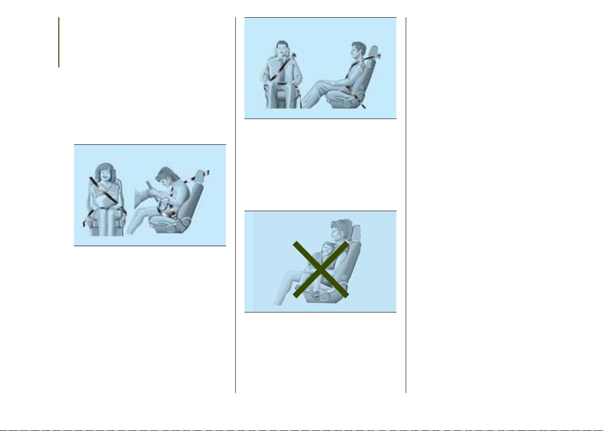
Pregnant women must position the
lower part of the belt very low down so
that it passes over the pelvis and under
the abdomen fig. 69. While pregnancy
SAFETY
increases, the driver must adjust both
seat and steering wheel to have full
control over the vehicle (pedals and
steering wheel should be easily
accessed). The maximum clearance
should be kept between the abdomen
and the steering wheel.
69
The seat belt must not be twisted. The
upper part must pass over the shoulder
and cross the chest diagonally fig. 70.
The lower part must adhere to the
pelvis, not to the abdomen of the
occupant. Never use devices (clips,
clamps, etc.) that hold the seat belt
away from your body.
J0A0148C
70
J0A0149C
Each seat belt must be used by only
one person. Never travel with a child
sitting on the passenger's lap and
a single belt to protect them both fig.
71. In general, do not place any objects
between the person and the belt.
71
J0A0150C
SEAT BELTS
MAINTENANCE
For keeping the seat belts in efficient
conditions, observe the following:
❒ always use the seat belt well
stretched and never twisted; make sure
that it is free to run without
obstructions;
❒ check seat belt operation as follows:
attach the seat belt and pull it hard;
❒ replace the belt after an accident of a
certain severity even if it does not
appear to be damaged. Always replace
the seat belt if the pretensioners were
deployed;
❒ to clean the seat belts, wash by hand
with water and neutral soap, rinse and
leave to dry in the shade. Never use
strong detergents, bleach, paints or any
other chemical substance which could
damage the belt fibres;
❒ prevent the retractors from getting
wet: their correct operation is only
guaranteed if water does not get inside;
❒ replace the seat belt when it shows
wear or cuts.
80

WARNING
79) The pretensioner may be used only
once. Contact a Jeep Dealership to have it
replaced after it has been deployed.
80) Removing or otherwise tampering with
seat belt and pretensioner components
is strictly prohibited. Any operations on
these components must be performed by
qualified and authorised technicians.
Always contact a Jeep Dealership.
81) For maximum safety, keep the back of
your seat upright, lean back into it and
make sure the seat belt fits closely across
your torso and pelvis. Always fasten the
seat belts for both the front and rear seats!
Travelling without wearing seat belts will
increase the risk of serious injury and even
death in the event of an accident.
82) If the belt has been subjected to high
levels of stress, for example after an
accident, it should be changed completely
together with the attachments, attachment
fixing screws and the pretensioner. In
fact, even if the belt has no visible defects,
it may have lost its resilience.
WARNING
33) Operations which lead to impacts,
vibrations or localised heating (over 100°C
for a maximum of six hours) in the area
around the pretensioner may damage or
deploy it. Contact a Jeep Dealership
should intervention be necessary on these
components.
CHILD PROTECTION
SYSTEMS
CARRYING CHILDREN
SAFELY
83) 84) 85) 86)
For optimal protection in the event of an
impact, all occupants must be seated
and wearing adequate restraint
systems, including newborn and other
children! This prescription is
compulsory in all EC countries
according to EC Directive 2003/20/EC.
Children below the height of 1.50
metres and until 12 years, must be
protected with suitable restraint
systems and be seated on the rear
seats.
Statistics on accidents indicate that the
rear seats give a better performance
when protecting children safety.
Compared with an adult, a child's head
is larger and heavier in proportion to
their body and the child's muscular and
bone structures are not fully developed.
Therefore, correct restraint systems
other than adult seat belts are
necessary to reduce as much as
possible the risk of injuries in the event
of an accident, braking or sudden
manoeuvre.
Children must be seated safely and
comfortably. Depending on the
characteristics of the child restraint
systems used, you are advised to keep
children in rearward facing child
restraint systems for as long as
possible (at least until 3–4 years old),
since this is the most protected position
in the event of an impact.
The choice of the most suitable child
restraint device depends on the weight
and size of the child. There are various
types of child restraint systems, which
can be secured to the vehicle by means
of the seat belts or with the ISOFIX/iSize anchorages.
It is recommended to always choose
the restraint system most suitable
for the child; for this reason always refer
to the Owner Handbook provided with
the child restraint system, to be sure
that it is of the right type for the children
it is intended for.
In Europe the characteristics of child
restraint systems are ruled by the
regulation ECE-R44, dividing them into
five weight groups:
Group Weight range
Group0 upto10kg
Group 0+ up to 13 kg
Group 1 9–18 kg
Group 2 15–25 kg
Group 3 22-36 kg
81

The ECE-R44 standard was recently
paired with the ECE R-129 regulation,
which defines the characteristics of
the new i-Size child restraint systems
SAFETY
(see the "Suitability of passenger seats
for i-Size child restraint system use"
paragraph).
All restraint devices must bear the
certification data, together with the
control mark, on a label solidly fixed to
the child restraint system which must
never be removed.
Lineaccessori Jeep offers child restraint
systems for each weight group. These
devices are recommended, having
been specifically designed for Jeep
vehicles.
FITTING A CHILD
RESTRAINT SYSTEM
WITH SEAT BELTS
The Universal child restraint systems
installed with the seat belts only are
type-approved on the basis of the ECE
R44 standard and are divided into
various weight groups.
IMPORTANT The figures are indicative
and provided for assembly purposes
only. Fit the child restraint system
according to the instructions, which
must be included.
Group 0 and 0+
Infants up to 13 kg must be carried with
a rearward facing child restraint system
of a type as shown in fig. 72 which,
supporting the head, does not induce
stress on the neck in the event of
sudden decelerations.
72
J0A0170C
The child restraint system is secured by
the car seat belts, as shown in fig. 72
and it must restrain the child in turn
with its own belts.
Group 1
Children of weight from 9 to 18 kg may
be carried in forward facing child
restraint systems fig. 73.
73
J0A0171C
Group 2
Children from 15 to 25 kg may use the
vehicle seat belts directly fig. 74.
74
J0A0172C
In this case, the child restraint system is
used to position the child correctly
with respect to the seat belts so that
the diagonal belt section crosses the
child’s chest and not the neck, and the
lower part is snug on the pelvis not
the abdomen.
82

Group 3
For children between 22 and 36 kg,
there are dedicated restraint systems
that allow the seat belt to be worn
correctly.
The fig. 75 shows the correct child
positioning on the rear seat.
75
J0A0173C
Children over 1.50 m in height can wear
seat belts like adults.
87) 88) 89)
83

PASSENGER SEAT COMPLIANCE WITH REGULATIONS ON UNIVERSAL CHILD
RESTRAINT SYSTEM USE
According to the European Directive 2000/3/EC the suitability of each passenger seat position for the fixing of universal child
restraint systems is shown in the following table:
SAFETY
Positioning the “Universal” child restraint system
Group Weight range Front passenger Rear central passenger Rear side passengers
Group 0, 0+ up to 13 kg U X U
Group 1 9–18 kg U X U
Group 2 15–25 kg U X U
Group 3 22–36 kg U X U
X = Seat not suitable for children in this weight category.
U = Suitable for child restraint systems in the “Universal” category, according to European Standard ECE-R44 for the specified
“Groups”.
84

FITTING A ISOFIX CHILD
RESTRAINT SYSTEM
90) 91) 92) 93)
The rear side seats of the vehicle are
equipped with ISOFIX attachments, for
fitting child restraint systems quickly,
simply and safely.
The ISOFIX system allows the ISOFIX
child restraint systems to be fitted,
without using the vehicle's seat belt,
but directly securing the child restraint
system to three anchorages present on
the vehicle. Traditional child restraint
systems can be fitted alongside ISOFIX
child restraint systems on different
seats in the same vehicle.
To install an ISOFIX child restraint
system, attach the it to the two metal
anchorages A fig. 76 located where the
rear seat cushion meets the backrest,
then fix the upper strap (available
together with the restraint system) to
the dedicated anchorage B located at
the bottom behind the backrest.
fig. 77 shows an example of a Universal
ISOFIX child restraint system for weight
group 1.
IMPORTANT The fig. 77 is indicative
and for assembly purposes only. Fit the
child restraint system according to
the instructions, which must be
included.
76
J0A0325C
NOTE When a Universal ISOFIX child
restraint system is used, only ECE R44
"ISOFIX Universal” (R44/03 or further
upgrades) type-approved child restraint
systems can be used (see fig. 78).
The other weight groups are covered
by specific ISOFIX child restraint
systems, which can be used only if
specifically tested for this vehicle (see
list of vehicles provided with the child
restraint system).
77
78
J0A0174C
J0A0326C
85

SUITABILITY OF PASSENGER SEATS FOR ISOFIX CHILD RESTRAINT SYSTEM USE
The table below shows the various installation possibilities for ISOFIX child restraint systems on seats fitted with the specific
anchorages in accordance with European standard ECE 16.
SAFETY
Weight categories Size category Device Front passenger
Group 0 (up to 10 kg) E ISO/R1
E ISO/R1
Group 0+ (up to 13 kg)
Group 1 (from 9 up to
18 kg)
D ISO/R2
C ISO/R3
D ISO/R2
C ISO/R3
B ISO/F2
B1 ISO/F2X
A ISO/F3
ISOFIX POSITIONS ON THE VEHICLE
XILX
XILX
XILX
X IL (*) X
XILX
X IL (*) X
X IUF X
X IUF X
X IUF X
Rear side
passengers
X ISOFIX position not suitable for ISOFIX child protection systems for this weight and/or size category.
IL Suitable for ISOFIX child restraint systems of the "Specific for the vehicle", "Restricted", or "Semiuniversal" categories, approved for this type of vehicle.
IL (*) The ISOFIX child restraint system can be installed by adjusting the front seat.
IUF Suitable for forward facing ISOFIX child restraint systems in the Universal category and type-approved for the use in the weight group.
Rear central
passenger
86

SUITABILITY OF
PASSENGER SEATS FOR
i-Size CHILD RESTRAINT
SYSTEM USE
The rear side seats of the vehicle are
type-approved to house the stateof-the-art i-Size child restraint systems.
These child restraint systems, built
and type-approved according to the
i-Size (ECE R129) standard, ensure
better safety conditions to carry
children on board a vehicle:
❒ the child must be transported
rearward facing until 15 months;
❒ child restraint system protection is
increased in the event of a side
collision;
❒ the use of the ISOFIX system is
promoted to avoid faulty installation of
the child restraint system;
❒ efficiency in the choice of the child
restraint system, which isn't made
according to weight anymore but
according to the child's height,
is increased;
❒ compatibility between the vehicle
seats and the child restraint systems is
better: the i-Size child restraint systems
can be considered as "Super ISOFIX",
this means that they can be perfectly
fitted in the type-approved i-Size seats,
but can also be fitted in the ISOFIX
(ECE R44) type-approved seats.
NOTE The vehicle seats, i-Size
type-approved, are marked by the
symbol shown in fig. 79.
79
J0A0450C
87

The following table, according to European legislation ECE 129, indicates the possibility to install i-Size child restraint systems.
i-Size POSITIONS ON THE VEHICLE
SAFETY
i-Size child restraint systems
Device Front passenger
ISO/R2 X i-U X
ISO/F2 X i-U X
Rear side
passengers
Rear central
passenger
i-U: suitable for Universal i-Size child restraint systems, both rearward facing and forward facing.
X: seat not suitable for Universal i-Size child restraint systems.
CHILD RESTRAINT SYSTEMS RECOMMENDED BY JEEP FOR YOUR JEEP
RENEGADE
Lineaccessori Jeep includes a complete range of child restraint systems to be fixed using the seat belt with three anchorage
points or the ISOFIX anchorages.
Weight group Child restraint system Type of child restraint system Child restraint system installation
Peg Perego Primo Viaggio SL
Type-approval number: E24
Group 0+: from 0 to
13 kg
040089
Universal/ISOFIX child restraint system.
It must be installed rearward facing,
using the vehicle seat belts only, or the
dedicated ISOFIX K base (which can
be purchased separately) and the
vehicle ISOFIX anchorages.
It must be fitted on the rear outer
seats.
88
ISOFIX K base

Weight group Child restraint system Type of child restraint system Child restraint system installation
Fair G0/1S
Type-approval number: E4
04443718
Group 1: from 9 up
to 18 kg
++
Fair ISOFIX RWF platform,
Jeep Renegade type specific
for G0/1S
or
Fair ISOFIX FWF platform,
Jeep Renegade type specific
for G0/1S
++
FAIR head restraint
Universal/ISOFIX child restraint system.
It can be fitted forward facing/rearward
facing using only the vehicle seat belts
or the Isofix anchorages.
Jeep recommends fitting it using the
rearward facing ISOFIX platform (RWF
specific for Jeep Renegade - to be
purchased separately) or the forward
facing ISOFIX platform (FWF specific
for Jeep Renegade - to be purchased
separately), the rigid head restraint (to
be purchased separately) and the
ISOFIX anchorages for the vehicle.
It must be fitted on the rear outer
seats.
89

Weight group Child restraint system Type of child restraint system Child restraint system installation
SAFETY
Group 2: from 15 kg
to 36 kg
Fair Junior Fix
Type-approval number: E4
04443721
It can only be fitted facing forwards,
using the three-point seat belt and the
ISOFIX anchorages of the vehicle, if
present.
IMPORTANT Jeep recommends fitting the child restraint system according to the instructions, which must be included.
Main recommendations to carry
children safely
❒ Install the child restraint systems on
the rear seat, which is the most
protected position in the event of an
impact.
❒ Keep children in rearward facing child
restraint systems for as long as
possible, until 3–4 years old if possible.
❒ If the passenger's front airbag is
deactivated always check the
dedicated warning light on the panel
located on the dashboard to make sure
that it has actually been deactivated.
❒ Carefully follow the child restraint
manufacturer's instruction supplied with
the child restraint system. Keep the
instructions in the vehicle along with the
other documents and this handbook.
Do not use second-hand child restraint
systems without instructions.
❒ Only one child is to be strapped into
each restraint system; never carry
two children using one child restraint
system.
❒ Always check that the seat belts do
not rest on the child’s neck.
❒ Always check that the seat belt is
well fastened by pulling on it.
❒ While travelling, do not let the child sit
incorrectly or unfasten the belts.
❒ Never allow a child to put the belt's
diagonal section under an arm or
❒ Never carry children on your lap,
even newborns. No-one could restrain
them in the event of an accident.
❒ In the event of an accident, replace
the child restraint system with a new
one.
WARNING
83) SEVERE DANGER When a front
passenger airbag is fitted, do not install
rearward facing child restraint systems on
the front passenger seat. Deployment of
the airbag in an accident could cause fatal
injuries to the baby regardless of the
severity of the collision. It is advisable to
always carry children in a child restraint
system on the rear seat, which is the most
protected position in the event of an
impact.
behind their back.
90
84) On the sun visor there is a label with
suitable symbols reminding the user that it
is compulsory to deactivate the airbag if
a rearward facing child restraint system is
fitted. Always comply with the instructions
on the passenger's side sun visor (see
the "Supplementary Restraint System
(SRS) - Airbag" paragraph).
85) Should it be necessary to carry a child
on the passenger side front seat in a rear
facing child restraint system, the passenger
side front airbag and side bag must be
deactivated through the display main menu
(see the instructions in the "Display"
paragraph, "Knowing the instrument panel"
chapter), verifying activation by checking
whether the
in the panel located on the dashboard.
Move the passenger's seat as far back as
possible to avoid contact between the child
restraint system and the dashboard.
86) Do not adjust the front or rear seat if a
child is seated on it or on the dedicated
child restraint system.
87) Incorrect fitting of the child restraint
system may result in an inefficient
protection system. In the event of an
accident the child restraint system may
become loose and the child may be
injured, even fatally. When fitting a restraint
system for newborns or children, strictly
comply with the instructions provided
by the Manufacturer.
OFF LED has switched on
88) When the child restraint system is not
used, secure it with the seat belt or with
the ISOFIX anchorages, or remove it from
the vehicle. Do not leave it unsecured
inside the passenger compartment. In this
way, in the case of sudden braking or an
accident, it will not cause injuries to the
occupants.
89) After installing a child restraint system,
do not move the seat: always remove
the child restraint system before making
any adjustment.
90) Always make sure that the chest
section of the seat belt does not pass
under the arms or behind the back of the
child. In the event of an accident the seat
belt will not be able to secure the child,
with the risk of injury, including fatal injury.
Therefore the child must always wear
the seat belt correctly.
91) Do not use the same lower anchorage
to install more than one child protection
system.
92) If a Universal ISOFIX child restraint
system is not fixed to all three anchorages,
it will not be able to protect the child
correctly. In a crash, the child could be
seriously or fatally injured.
93) Fit the child restraint system only when
the vehicle is stationary. The child restraint
system is correctly fixed to the brackets
when you hear the click. Follow the
instructions for assembly, disassembly and
positioning that the Manufacturer must
supply with the child restraint system.
SUPPLEMENTARY
RESTRAINT SYSTEM
(SRS) - AIRBAG
The vehicle is equipped with:
❒ front driver airbag;
❒ front passenger airbag;
❒ driver and passenger front side bags
for pelvis, chest and shoulder
protection (Side bags);
❒ front and rear side passenger side
bags for head protection (window bag).
FRONT AIRBAGS
The front driver/passenger airbags and
the driver's knee bag (where provided)
protect the front seat occupants in
the event of frontal impacts of
medium/high severity, by placing the
bag between the occupant and the
steering wheel or dashboard.
Therefore non-activation in other types
of collisions (side impacts, rear shunts,
roll-overs, etc.) does not indicate a
system malfunction.
Driver and passenger front airbags are
not a replacement of but
complementary to the seat belts, which
should always be worn, as specified
by law in Europe and most nonEuropean countries.
91

In the event of impact, those not
wearing a seat belt are projected
forwards and may come into contact
with the bag which is still inflating. The
SAFETY
protection offered by the bag is
compromised in these circumstances.
The front airbags may not activate in
the case of a frontal impact against
highly deformable objects not involving
the front surface of the vehicle (e.g.
wing collision against guard rail) or in
the case of the vehicle wedging under
other vehicles or protective barriers
(e.g. under trucks or guard rails).
Failure to activate in the conditions
described above is due to the fact that
they may not provide any additional
protection compared with seat belts, so
their activation would be inappropriate.
In these cases, non-deployment does
not indicate a system malfunction.
Driver's side front airbag
94) 95)
This consists of an instantly inflating
cushion contained in a special
compartment in the centre of the
steering wheel fig. 80.
80
J0A0176C
Passenger side front airbag
96)
This consists of an instantly inflating
bag contained in a special recess in the
dashboardfig. 81, this bag has a larger
volume than that of the driver's.
81
J0A0177C
Passenger side front airbag
and child restraint systems
Rearward facing child restraint systems
must NEVER be fitted on the front
seat with an active passenger side
airbag since in the event of an impact
the airbag activation may cause fatal
injuries to the transported child.
ALWAYS comply with the instructions
on the label stuck on the passenger
side sun visor fig. 82.
82
J0A0190C
92

Deactivating the passenger
side airbags: front airbag
and side bag
If a child must be carried on the front
seat in a rearward facing child restraint
system, deactivate the passenger
side front airbag and front side bag.
Use the display Menu to deactivate.
The LEDs OFF and ON are on
the dashboard trim. Moving the ignition
device to MAR, the two LEDs switch
on for a few seconds. Otherwise,
contact a Jeep Dealership.
During the first seconds, the activation
of the LEDs does not actually show
the passenger protection status, but
only checks its correct operation. After
a test of a few seconds, the LEDs
will indicate the status of the passenger
airbag protection.
83
J0A0051C
Passenger protection activated: the
LED
ON fig. 83 switches on.
Passenger protection deactivated:
the LED
OFF fig. 83 switches on.
The LEDs may light up with various
intensity levels depending on the
vehicle conditions. The intensity may
vary during the same key cycle.
93

Passenger front airbag and child restraint system: WARNING
SAFETY
94
84
J0A0215

SIDE BAGS
To help increase occupants protection
in the event of side impact collisions,
the vehicle is equipped with front side
bags and window bags.
Side bags
These comprise two bags located in
the front seat backrests fig. 85 which
protect the pelvis, chest and shoulder
area of the occupants in the event
of a side impact of medium/high
severity. They are marked by the
"AIRBAG" label sewn on the outer side
of the front seats.
Window bag
This comprises a "curtain" bag housed
behind the roof side linings and covered
by special trims fig. 86. They are
designed to protect the head of front
and rear occupants in the event of
a side collision, thanks to the
wide cushion inflation surface.
The deployment of side bags in the
event of side impacts of low severity is
not required.
In the event of a side impact, the
system provides best protection if the
passenger sits on the seat in a correct
position, thus allowing correct window
bag deployment.
97) 98) 99) 100) 101) 102) 103) 104) 105) 106) 107)
108)
Important
Do not wash the seats with water or
pressurised steam (wash by hand or at
automatic seat washing stations).
The front and/or side airbags
may activate in the event of sharp
impacts to the underbody of the vehicle
(e.g. impact with steps, pavements,
potholes or road bumps etc.).
When the airbag deploys it emits a
small amount of dust: the dust is
harmless and does not indicate the
beginning of a fire. The dust may irritate
the skin and eyes however: in this
case, wash with neutral soap
and water.
Airbag checking, repair and
replacement must be carried out at a
Jeep Dealership.
85
J0A0178C
If the vehicle is scrapped, have the
airbag system deactivated at a Jeep
Dealership.
Pretensioners and airbags are deployed
according to different logics on the
basis of the type of collision. Failure to
deploy of one of the devices does
not necessarily indicate a system
malfunction.
86
J0A0180C
95

WARNING
94) Do not apply stickers or other objects
SAFETY
on the steering wheel, on the dashboard in
the passenger side airbag area, on side
upholstery on the roof or on the seats.
Never put objects (e.g. mobile phones) on
the passenger's side dashboard since
they could interfere with correct inflation of
the airbag and also cause serious injury
to the passengers.
95) Always drive keeping your hands on
the steering wheel rim so that the airbag
can inflate freely if necessary. Do not drive
with your body bent forward. Keep your
back straight against the backrest.
96) When an active passenger airbag is
fitted, DO NOT install rearward facing child
restraint systems on the front passenger
seat. Deployment of the airbag in an
accident could cause fatal injuries to the
child regardless of the severity of the
impact. Therefore, always deactivate the
passenger side airbag when a rearward
facing child restraint system is installed on
the front passenger seat. The front
passenger seat must also be positioned
back as far as possible in order to prevent
the child restraint system from coming
into contact with the dashboard.
Immediately reactivate the passenger
airbag as soon as the child restraint system
has been removed.
97) Do not hook rigid objects to the coat
hooks and to the support handles.
98) Do not rest your head, arms or elbows
on the door, windows or the area in which
the window bag is located to avoid
possible injury during inflation.
Never lean head, arms and
99)
elbows out of the window
100) If the
switch on when the ignition device is
moved to MAR or if it stays on when
driving, there might be a fault in the
restraint systems; in this case, the airbags
or pretensioners may not deploy in the
event of an accident or, in a lower number
of cases, they could deploy erroneously.
Before proceeding, contact a Jeep
Dealership immediately to have the system
checked.
101) On some versions, if the
(located on the dashboard panel) is faulty,
warning light
panel.
102) If a side bag is present, do not cover
the front seat backrests with extra covers.
103) Do not travel carrying objects in
your lap, in front of your chest or between
your lips (pipe, pencils, etc.). They could
cause severe injury if the airbag is
deployed.
104) If the has been subject to theft,
attempted theft, vandalism, or flooding,
have the airbag system inspected at a
Jeep Dealership.
warning light does not
OFF LED
lights up in the instrument
105) If the ignition device is at MAR, even if
the engine is switched off, airbags may
be deployed when the vehicle is stationary
and hit by another vehicle. Therefore,
even if the vehicle is stationary, when an
active front passenger airbag is fitted, DO
NOT install rearward facing child restraint
systems on the front passenger seat.
Deployment of the airbag following an
impact could cause fatal injuries to the
child. Therefore, always deactivate the
passenger side airbag when a rearward
facing child restraint system is installed on
the front passenger seat. The front
passenger seat must also be positioned
back as far as possible in order to prevent
the child restraint system from coming
into contact with the dashboard.
Immediately reactivate the passenger
airbag as soon as the child restraint system
has been removed. Finally, remember that
if the ignition device is at STOP, no safety
device (airbags or pretensioners) will
activate following an impact; therefore if
these devices do not activate this cannot
be considered as signal of the system
malfunction.
106) If the airbag failure warning light is
faulty this will be signalled by an airbag
failure icon lighting up in the instrument
panel display with a dedicated message.
The pyrotechnic charges are not disabled.
Before proceeding, contact a Jeep
Dealership immediately to have the system
checked.
107) The front airbag deployment threshold
is higher than that of the pretensioners.
When the impact is between the two
deployment thresholds, it is normal that
pretensioners only are engaged.
96

108) The airbag does not replace seat
belts, but increases their efficiency.
Because front airbags are not deployed for
low-speed crashes, side collisions,
rear-end shunts or rollovers, occupants are
protected, in addition to any side bags,
only by their seat belts, which must
therefore always be fastened.
97

STARTING AND DRIVING
Let’s get to the "heart" of the vehicle:
seeing how you can exploit all of its
potential to the full.
We’ll look at how to drive it safely in any
situation, so that it can be a welcome
companion, with our comfort and
our wallets in mind.
STARTING AND DRIVING
STARTING THE ENGINE ................. 99
ELECTRIC PARKING BRAKE (EPB).100
MANUAL GEARBOX .......................103
AUTOMATIC TRANSMISSION.........103
STOP/START SYSTEM ...................106
SPEED LIMITER ..............................107
ELECTRONIC CRUISE CONTROL ..108
FOUR WHEEL DRIVE - JEEP
ACTIVE DRIVE (4WD) AND JEEP
ACTIVE DRIVE LOW (4WD LOW) ....109
SELEC-TERRAIN ............................111
PARKSENSE SYSTEM ....................112
LANESENSE SYSTEM (LANE
CROSSING WARNING) ...................114
REAR CAMERA (PARKVIEW®
REAR BACKUP CAMERA) ..............115
TOWING TRAILERS ........................117
REFUELLING THE VEHICLE ...........120
98
 Loading...