

Page 1
Meaning
Automatic Gain Control
Base Transmitting Station (Cell Tower)
Code Division Multiple Access
Decibel – (A unit of measure for signal strength)
Downlink (Communication channel from cell tower to mobile device)
Outdoor Antenna (Antenna that donates an input signal)
Global System for Mobile Communications
Integrated Digital Enhanced Network
Liquid Crystal Display
Light Emitting Diode
Long Term Evolution
Mobile Station
Personal Communication System
Radio Frequency
Uplink (Communication channel from mobile device to cell tower)
AGC
BTS
CDMA
dB
DL
Donor
GSM
iDEN
LCD
LED
LTE
MS
PCS
RF
UL
Abbreviations…………………………………………..………………………………..2
Safety……………………………………………………………………….……………….2
1. Introduction …………………………………………………...……………………..3
2. Features & Functions ………………………………….……………………….4
3. Installation Procedure……………………………………….....………………6
4. LED Operation Status………………..…………………………………………7
5. Trouble Shooting………………………………………………..…….…..………8
Specifications……………………………………………………………………..…….9
FCC Statement………………………………………………………...……….……10
Terminology
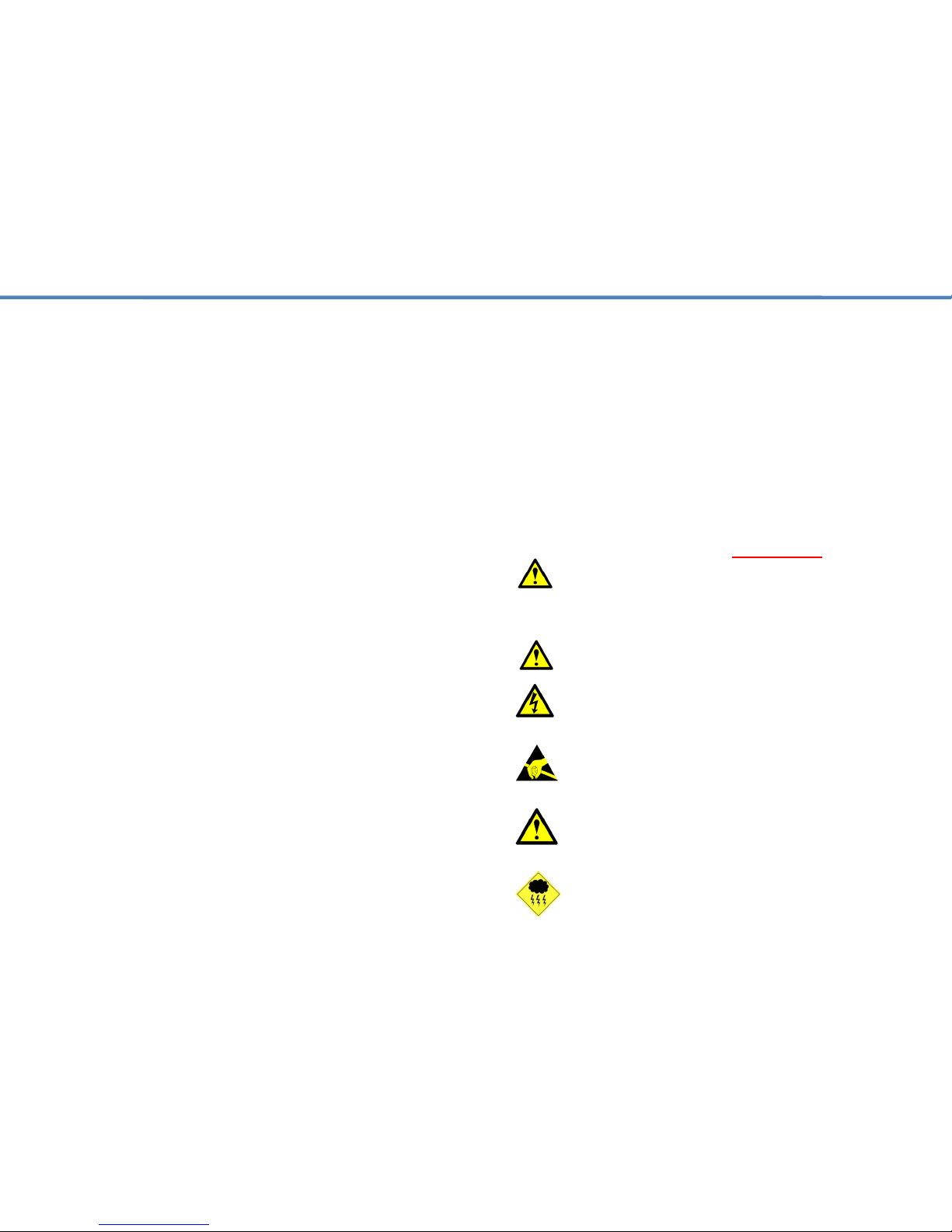
User Warnings – MUST READ!
1. This amplifier must ONLY be used for the purpose it was
intended for. Making any alternations to the design layout
without first consulting with a trained technician can result in
interference to the operator’s network and liability by the end
user.
2. Please read this entire manual carefully before using this product!
3. Only the power supply that came with the amplifier should be
used at all times. It is highly recommended that the repeater
is grounded and lightning protection used.
4. Do not attempt to open any part of the amplifier. This will void
the warranty and can cause an electric shock. Electrostatic
can also cause damage to the internal components.
5. Please keep away from any heating-equipment, because the
amplifier will dissipate heat when working. Do not cover the
amplifier with anything that influences heat-dissipation.
6. Do not place or mount the amplifier in a location that is exposed
to the elements. This will void the warranty and can cause an
electric shock.
Page 2
1. Introduction
The WCB Series Pre-amplifier from JDTECK was designed to work in
tandem with a cellular repeater for applications where the donor signal
reaching the cellular repeater is very weak. This results in poor system
performance and a reduced coverage area.
Poor input signal can be the result of distance from the cell tower,
obstructions affecting a good line of sight to the cell tower or an excessively
long coaxial cable coming from the donor antenna. Using a pre-amplifier will
help eliminate the effects of this problem by first filtering and then amplifying
the signal before it gets into the cellular repeater.
The WCB Series Pre-Amplifier is designed to be installed between the donor
antenna and the cellular repeater.
Another benefit of the WCB Series pre-amplifier is that it can help to
increase the uplink power level of the repeater going back to the BTS or cell
tower. This helps improve the stability of the signal and also reduces call
drops when deployed very far from a cell tower.
The WCB Series Pre-amplifier is also equipped with an alarm monitoring
feature. This circuit monitors the uplink gain of the repeater when coupled
with the pre-amp to ensure it operates within safe limits. There is also an
automatic gain control feature on the pre-amplifier which allows it to adjust to
the environment automatically.
The pre-amplifier is supplied with N type female input / output RF connectors
and is available in a 35dB gain or 15dB gain model. An optional model with
SMA type female connectors is also available.
2. Features & Functions
Sleek attractive housing
LED indicators to monitor environmental status
Supports all technologies including, GPRS, HSDPA, UMTS & LTE
Low power consumption
ALC function. (Auto Limit Control)
AGC function. (Automatic Gain Control)
Heat Sink cooling fins to dissipate heat quickly and efficiently
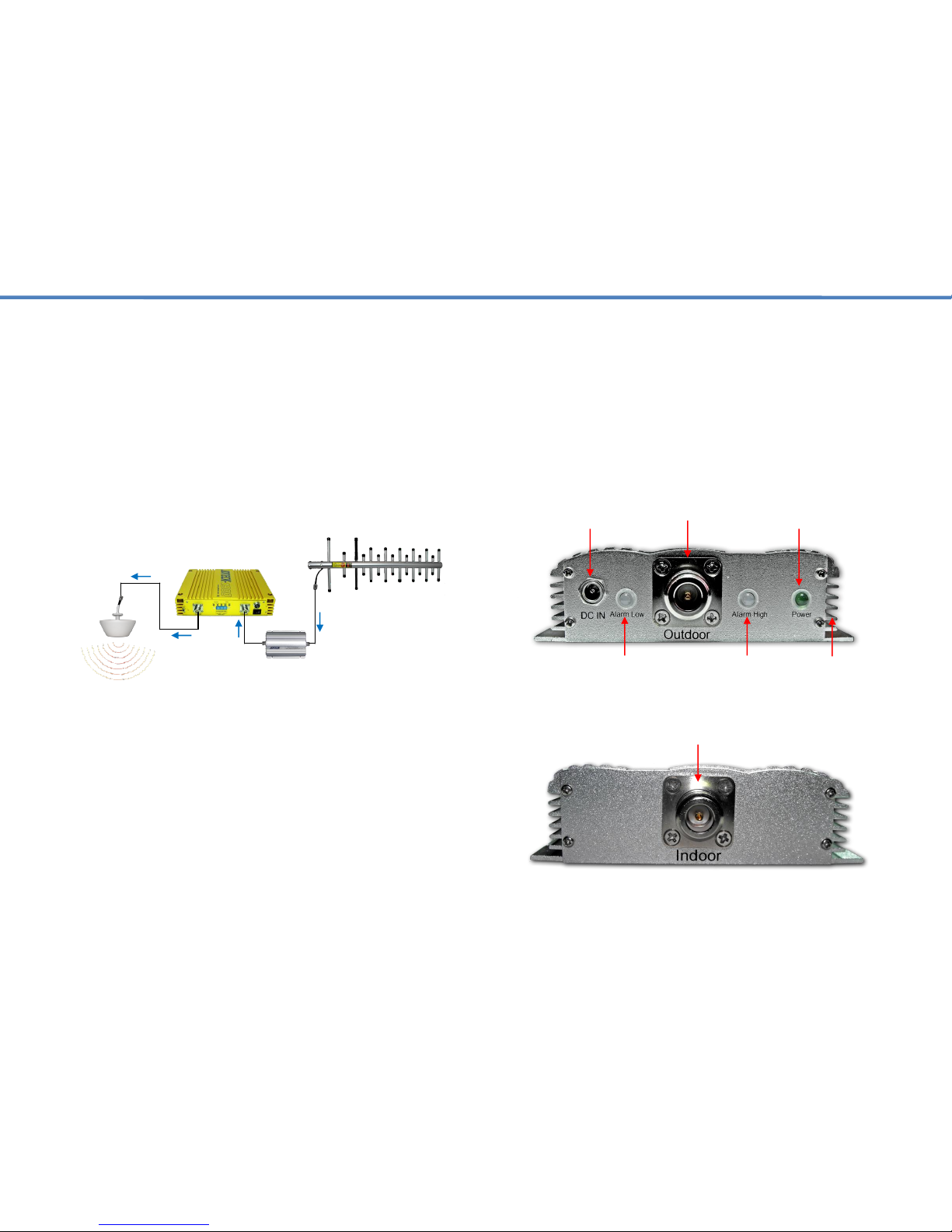
DC Power Plug
Outdoor Port
Power LED
Low Alarm
High Alarm
Heat Sink Fins
Indoor Port
Dome Ant.
Repeater
Pre-amp
Donor Ant.
Page 3
2. Features & Functions – Cont.
3. Installation Procedure
The WCB Series pre-amplifier must be installed between the donor antenna
and the cellular repeater. Do not install on the indoor side of the repeater.
Installing this amplifier in a temperature controlled environment or any
location where there is good ventilation free of moisture or any other heat
source is recommended. An AC power source will be required to power the
unit. The location you choose for the amplifier should allow you to easily
monitor the active LED’s on the side panel.
1. Align pre-amplifier to the position you have selected for it. Double check
your distance between the pre-amplifier and the repeater to ensure your
jumper cable mating these two devices is long enough.
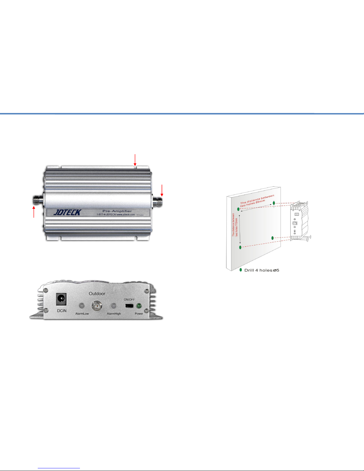
2. Mark the position, drill holes for the mounting screws and affix in position.
3. Connect RF cables and power cables to the pre-amplifier respectively.
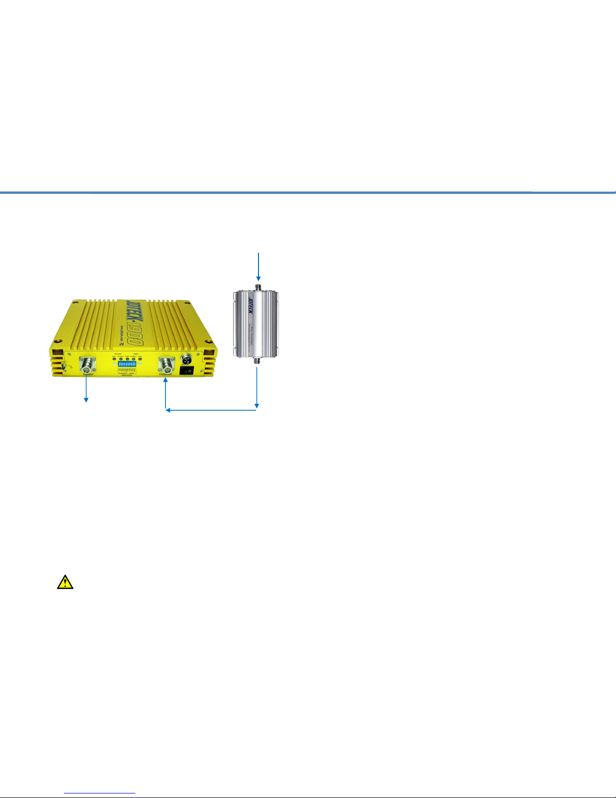
The donor antenna coax must connect with the “Outdoor” port of the
pre-amplifier, whereas the “Indoor” port of the pre-amplifier must
connect with the “Outdoor” port of the repeater.
4. After installing the pre-amplifier as described as above, power on the pre-
amplifier and cellular repeater to check the LED operation status.
RF Port
RF Port
Mounting Slot
(Optional SMA Model Type)
Page 4
3. Installation ~ Cont.
4. LED Operation Status
There are 3 LED’s located on the side panel of the pre-amplifier. One is for
the Power LED and two are for the Alarm LED’s. (Dual Band Model) For
triple band line amplifiers, there are 4 LED’s.
If the alarm status is RED that means the uplink power of the system is too
high. To adjust this, you need to attenuate the uplink gain of the cellular
repeater in 2dB increments till the LED turns green.
If the alarm status on the repeater is RED or Amber, you will need to
attenuate the downlink gain of the repeater to get the alarm to go green.
After you have made any adjustments, please monitor the alarm LED for a
minute or so to ensure the alarm status is a steady green and not flickering
to RED. If it is flickering, then you need to add more attenuation.
Note: If the pre-amplifier is switched off while connected to the
repeater, it will not pass the RF signal coming from the donor antenna.
5. Troubleshooting
Q1. Why is there still no signal after installing the equipment?
Answer:
1. Check the power source of the amplifier and repeater.
2. Check the connector of outdoor antenna is tight or not.
3. Check the connectors of RF cable are tight or not.
4. Check the outdoor signal is strong enough or not.
5. Check to make sure the antenna is installed correctly.
6. Check the connector of indoor antenna is tight or not.
7. Check the cable type is suitable or not.
Q2. Why the signal strength is too weak on the edge of area?
Answer:
1. Check the outdoor signal and antenna direction.
2. Check repeater is full gain or not.
3. Check all of the connectors are tight.
4. Change the location of outdoor/indoor antenna.
5. Check the cable type is suitable or not.
6. Deploy more indoor antennas.
Q3. Why can’t I make a call after installation, even though I can
detect a signal?
Answer:
1. Check LED status of repeater to make sure alarms are green.
2. Change the location of outdoor / indoor antenna.
3. Reduce the UL gain of the repeater.
Q4. The signal is not stable after turning on the system.
Answer:
1. Check to see if the outdoor signal is stable or not.
2. Check the location of the donor antenna. Too close to other antennas.
3. Check the RF cable is broken or not and has no coils.
4. Confirm direction of donor antenna in relation to cell tower.
Q5. Why is the LED on the front of the repeater not lit?
Answer:
1. Check the power source is normal or not.
2. MUTE feature is active. Attenuate gain of repeater and cycle power.
Donor Signal
Outdoor Port
Indoor Port
Outdoor Port
To Indoor Ant.
Indoor Port
(Signal Flow Path)
Page 5
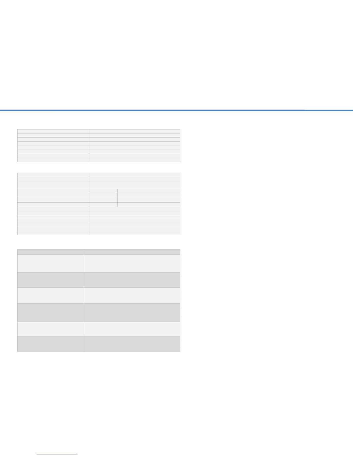
Mechanical Specifications
Input / Output Port
N-Female
Impedance
50 Ω
Dimensions (W x D x H)
135 x 125 x 36mm
Weight
≤0.7Kg (1.5 Lbs)
Operating Temperature
-10°C ~ 50°C
Environment Conditions
IP40
Switching Adapter
Input AC 90~265V, Output DC 9V / 3A
Power Consumption
12 Watts
NOTES
_________________________________________________________________________________
_________________________________________________________________________________
_________________________________________________________________________________
_________________________________________________________________________________
_________________________________________________________________________________
_________________________________________________________________________________
_________________________________________________________________________________
_________________________________________________________________________________
_________________________________________________________________________________
_________________________________________________________________________________
_________________________________________________________________________________
_________________________________________________________________________________
_________________________________________________________________________________
_________________________________________________________________________________
FCC Statement
PLEASE NOTE: It is normal for your repeater to be quite warm while in use.
This device complies with part 15 of the FCC Rules. Operations subject to
the following two conditions: (1) This device may not cause harmful
interference, and (2) this device must accept any interference received,
including interference that may cause undesired operation. Changes or
modifications not expressly approved by the party responsible for
compliance could void the user's authority to operate the equipment.
FCC Radiation Exposure Statement:
This equipment complies with FCC radiation exposure limits set forth for an
uncontrolled environment . This equipment should be installed and operated
with minimum distance 20cm between the radiator& your body. This
transmitter must not be co-located or operating in conjunction with any other
antenna or transmitter.
Frequency Specifications
Model
WCB-819
FCC ID
SQXWCB-819
Filter Bandwidth
GSM & CDMA 25MHz | PCS 60MHz
DCS 75MHz | WCDMA 60MHz | LTE 11Mhz
Output power
Downlink
Uplink
≥0dBm
≥20dBm
Max. Gain
≥35dB
≥35dB
Noise
-
≥7dB
AGC Range
≥10dB
V.S.W.R
≤2.8
Group Delay
≥ 1.5μs
Frequency Stability
≤0.01ppm
LED Alarm Status
Standard
Power LED
Power Indicator
ALC LED
Orange @ ALC 1~5dB, Red @ ALC 15dB~20dB
Model Specifications
Classification
Bandwidth Range (MHz)
A. Frequency Range
CDMA / TDMA / AMPS / GSM 850
PCS / CDMA / GSM / GPRS
800 / 1900Mhz
DL - 869-894 / 1930-1990
UL - 824-849 / 1850-1910
B. Frequency Range
(GSM / DCS)
900 / 1800Mhz
DL - 935-960 / 1805-1880
UL - 890-915 / 1710-1785
C. Frequency Range
(GSM / WCDMA / UMTS)
900 / 2100Mhz
DL - 935-960 / 2110-2170
UL - 890-915 / 1920-1980
D. Frequency Range
CDMA / TDMA / PCS / CDMA / GSM /
GPRS / AWS
1900 / 1721Mhz
DL - 1930-1990 / 2110-2155
UL - 1850-1910 / 1710-1755
E. Frequency Range
AWS
1700 / 2100Mhz
DL - 2110-2155
UL - 1710-1755
F. Frequency Range
(WCDMA / UMTS)
2100Mhz
DL - 2110-2170
UL - 1920-1980
 Loading...