

Page 1

User’s Manual
for Wireless Repeater
Model No : JD65-XT ( PCS 1.9G Pico Repeater )
JDTECK LTD
JDTECK LTD 1page Rev. 1.0
Page 2

n Introduction
The JD65-XT model, a mobile communications repeater, is affected by neither
configuration of the ground nor base station’s signals. To improve call quality at smallsized area with radio wave interference ( 50 ㎡ ) or mobile communications service
interference area, the repeater amplifies and transmits signals of base station and
mobile station.
Being suitable to frequency bandwidth of customer, the repeater is to be produced
enough to handle, install and maintain it with ultra small-sized model .
To maintain specific level of output signal, the repeater has built-in AGC and ALC
circuits, which can automatically control gain of the repeater depending upon strength
of input signals. In addition, to prevent the repeater from producing errors due to
excessive from outside or oscillation phenomenon and having adverse effects on base
station, the repeater runs auto shutdown functions, which switches the repeater’s
power automatically.
Feature & Functions
1. AGC : Automatic Gain Control
2. ALC : Automatic Limit Control
3. Automatic output interception function (MUTE)
4. RSSI : Received Signal Strength Emission
5. Small size, light - weight
6. Simple installation & Maintenance
JDTECK LTD 2page Rev. 1.0
Page 3
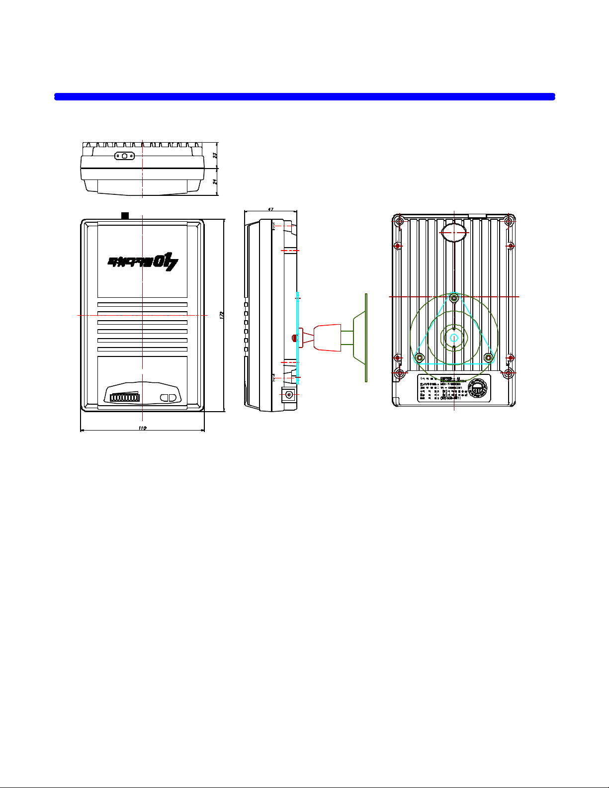
Name & Function by each parts
- Front - - Side - - Back Side -
JDTECK LTD 3page Rev. 1.0
Page 4

Ø Repeater
The repeater amplifies and transmits signals of base station and mobile station. The
Patch antenna, as remote antenna, is built in front of repeater.
① Donor ANT
Donor Ant., which has a SMA(F) connector to be connected with the feeding cables
② RSSI ( Received Signal Strength Emission ) Indicator
The lamp at bottom in front of the repeater shows operation status. Green-colored
lamp turns ON, on the basis of received signal
RX LED Status
-less than56dB:
-53dB±1.5 dB :
-50dB±1.5 dB :
-47dB±1.5 dB :
-44dB±1.5 dB :
-41dB±1.5 dB :
-38dB±1.5 dB :
-35dB±1.5 dB :
-32dB±1.5 dB :
-More than 9dB:
●○○○○○○○○○
●●○○○○○○○○
●●●○○○○○○○
●●●●○○○○○○
●●●●●○○○○○
●●●●●●○○○○
●●●●●●●○○○
●●●●●●●●○○
●●●●●●●●●○
●●●●●●●●●●
③ MUTE ( Auto Shut Down )
Mute prevents abnormal output from being radiated by reading strength of output
signal at emission of abnormal output. It is shut down against more than +9dBm
signal automatically.
- MUTE LED ( Red Colored Lamp ) : ON for a 5sec and OFF for a 2sec, repeatedly
- RSSI LED ( Green Colored Lamp ) : OFF
JDTECK LTD 4page Rev. 1.0
Page 5

④ PWR
Exterior adapter having AC 110-220 V input supplies DC 7 V power to the repeater
to run active circuits. LED on
⑤ DC Jack
DC Jack is a terminal to supply required powers into repeater through the power
supply adapter.
⑥ Patch Antenna
Patch Antenna, which can forward the RF signal from base station to cellular
subscriber station, receive the signal from cellular subscriber station
Ø Power Supply Adapter
Exterior adapter having AC 100– 240V input supplies DC 7 V power to the repeater to
run active circuits.
Ø RG400 RF Cable
RG 400 RF Cable, which is used for connecting with feeding cable coming from
Donor antenna.
Ø Bracket
The bracket is used for fixing the repeater on the wall.
JDTECK LTD 5page Rev. 1.0
Page 6
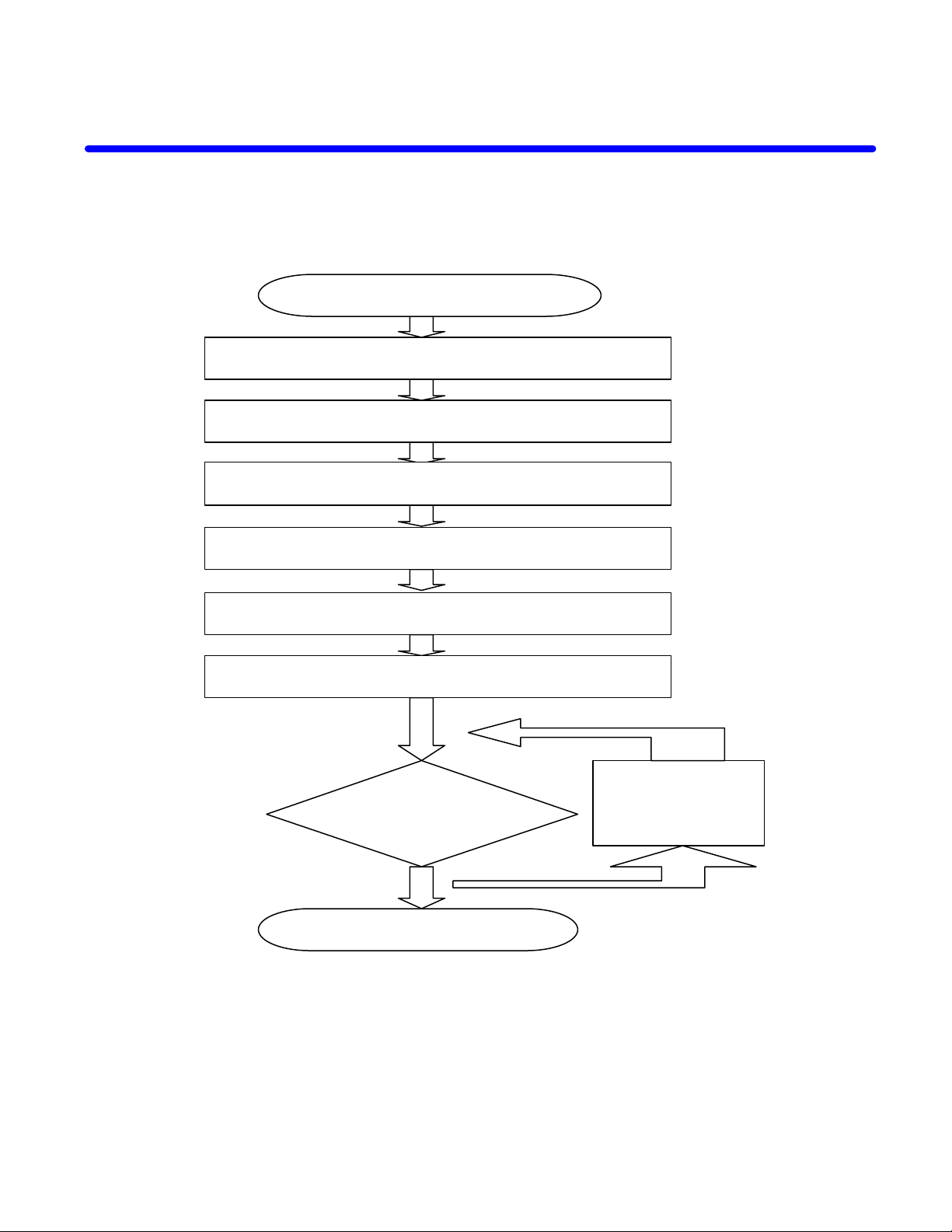
How to install the system
Completion
Testing
Checking the contents
Typical Installation Instructions
Install Repeater inside at convenient location on a wall
Fix repeater body on a wall
Installation exterior antenna & Laying Feeding Cables
Measurement of Receiving Level from Base Station
Connect power supply adapter
Adjust the direction of Antenna
for calling quality
Inspection
JDTECK LTD 6page Rev. 1.0
Page 7

Ø Checking the contents
Ø Put the repeater at the place where to install it
Ø Install Repeater inside at convenient location on a wall
Ø Installation Exterior Antenna & Laying Feeding Cables
Ø Measurement of Receiving Level from Base Station
1) Connect feeding cable, which has been connected with directional antenna for base
station, with input of spectrum analyzer.
2) Set measurement environment of Frequency, Span, BW and Amplitude, etc of the
spectrum analyzer.
3) Verify Channel Power value of input signal.
Ø Connect to RG 400 RF Cable
Ø Connect power supply adapter
Caution: Make sure 120V available to connect power transformer (do not power up)
Ø Adjust the direction of Antenna
To improve calling qualities, adjust the direction of Patch Antenna in front of body.
Ø Testing for calling qualities
JDTECK LTD 7page Rev. 1.0
Page 8
User Attention
Ø Do not open the case of repeater
Ø Do not excessive pressure to Repeater.
Ø Please use a rated voltage.
Ø The repeater must have been installed considering environmental factor.
n Troubleshooting
1) The power LED at the front turns OFF
Causes Auction
Power cable of the power supply
unit has not been connected.
Failure of the LED Replace the LED
2) The repeater transmits no signal
Causes Action
Coaxial cable connecting the
repeater and measuring system is
defective
Power system of interior of the
repeater has not been connected.
Auto shutdown
Check connection of power system
Replace coaxial cable
Check power connection of PCB of interior of
the repeater
Check a failure of the repeater and input of
wrong signal into the repeater
JDTECK LTD 8page Rev. 1.0
Page 9

Specifications
VSWR
Weight
Electrical Specifications
Frequency Range
Gain
Gain Flatness
Frequency Stability
ALC Range
Input Level (max)
Output Level (max)
Shutdown Level
Tx/Rx Isolation
Noise Figure
Spurious Emission ≥29dBc@±885KHz
≥34dBc@±1.98MHz
Propagation Delay
Control
Impedance
FWD: 1930 ~ 1990MHz, RVS: 1850 ~ 1910 MHz
50 ± 2 dB
≤ 4.5 dB (@ 60 MHz BW)
≤ ± 0.03 ppm
30dB
-120 ~ -40 dBm
10 dBm / Total
14 ~ 16 dBm/Total@1FA
≥ 85 dB
≤ 5 dB
≤ 1.5:1
≤ 1 us
No Control Interface
50 Ω
Mechanical Specifications
Operating Temp.
Cooling
Input/Output Connector
Power
Dimensions (W x H x D)
-10 ~ +50 °C
Convection
SMA (Female)
7 V DC / 100 ~ 240 V AC
180x120x50 mm
800 g
JDTECK LTD 9page Rev. 1.0
 Loading...