

Page 1
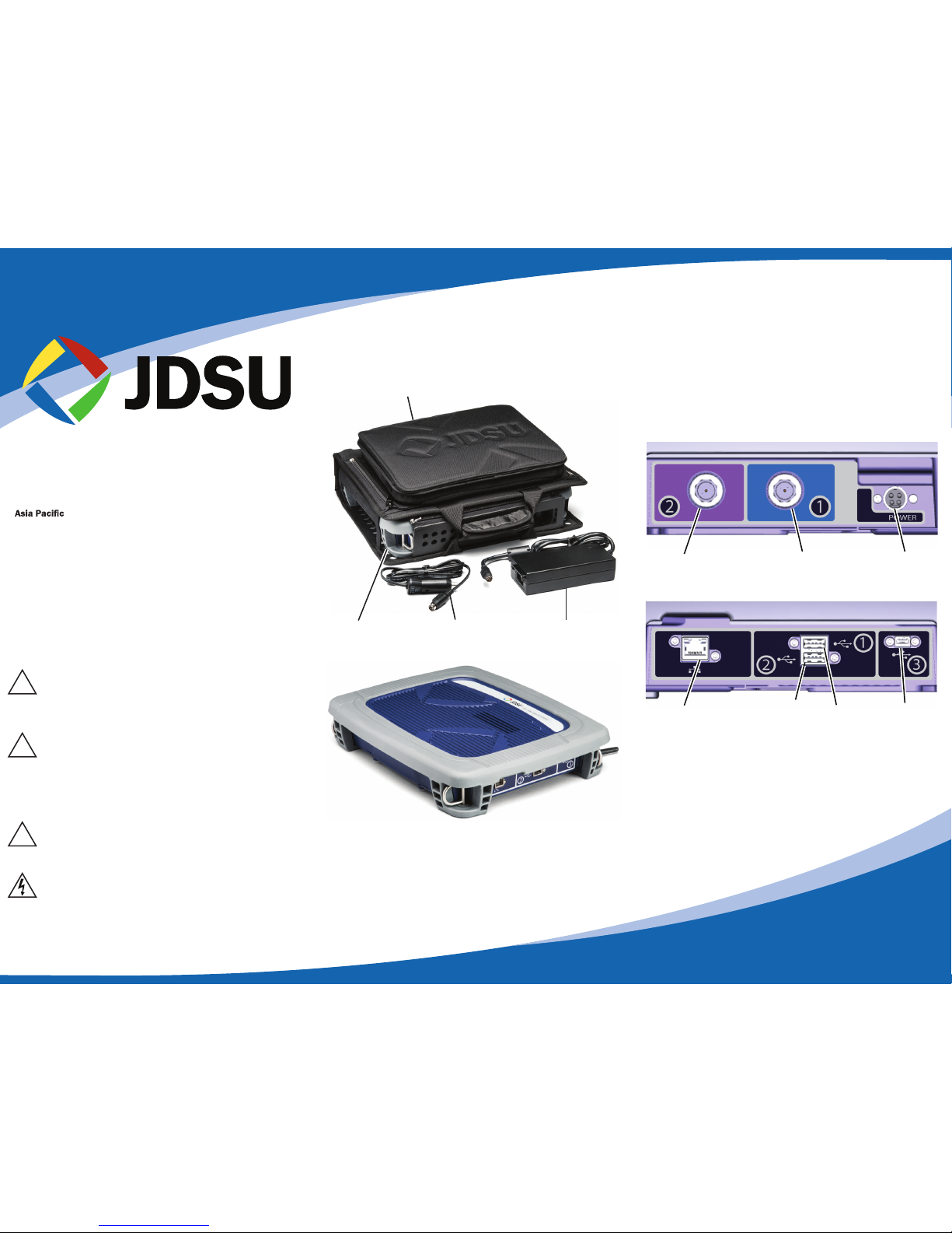
Signal/PowerConnectors
The VSE-1100 is equipped with dual F-connectors for
differential signal analysis and a power input on the left
side. 12VDC power can be supplied to the unit from the
included AC power adapter or 12VDC power cable.
On the right side are the control connectors - a USB
connector for direct atachment to the tablet and an
Ethernet port connector.
WiFi Antenna
A standard WiFI antenna is located on the rear of the unit
and can be repositioned for maximum reception by
rotating as needed.
VSE-1100 Quick Start Guide
What is in the box?
VSE-1100 Basics
VSE-1100 Warnings
JDSU Sales
North America Tel: 1 855 ASK JDSU (1 855 275 5378)
Latin America Tel: +1 954 688 5660 Fax: +1 954 345 4668
Tel: +852 2892 0990 Fax: +852 2892 0770
EMEA Tel: +49 7121 86 2222 Fax: +49 7172 86 1222
JDSU
Technical Assistance Center
Tel:
855 275 5378 / 855 ASK JDSU
Option 3-1-2
email: catvsupport@jdsu.com
VSE-1100
Case
AC Power Cable
and Adapter
12V DC
Power Cable
WARNING
If the equipment is used in a manner not specified
by the manufacturer, the protection provided by the
equipment may be impaired.
WARNING
Do not use this product in the vicinity of a gas leak
or in any other explosive environment.
WARNING ELECTRICAL SHOCK
Electrical shock may result in serious injury or death.
Be sure the AC cord is connected to the correct
voltage mains. Use only the universal power supply
with the test set.
!
!
!
WARNING
Do not disassemble the meter.
Do not attempt to service this product yourself.
There are no user-serviceable parts inside.
Contact the appropriate JDSU representative for
repair or calibration.
22048437-001 Rev003
Input-Upstream
85MHz Only
Input-Upstream/
Downstream
Power
Ethernet Port USB Conn. 2 Micro-USB
Tablet
Connection
Left side
Right side
Page 2
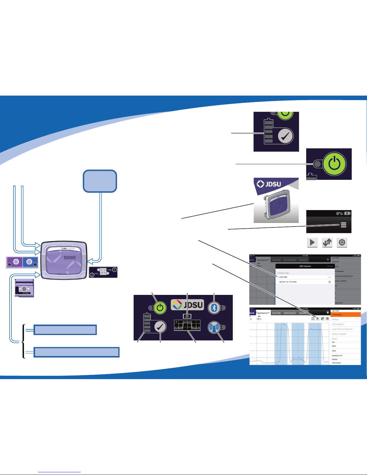
Connection via USB
1. Battery Check – press Battery Check button on
keypad. If the battery is not charged, plug power
cord into the VSE-1100. As battery charges, level
indicator will update.
2. VSE-1100 Power On – depress and hold the keypad
ON/OFF button for 2 seconds. Indicator will flash
and after 15-60 seconds it will stay illuminated.
3. Plug – USB cable from USB on tablet to USB1 on
VSE-1100.
4. Power on Tablet – The tablet should automatically
connect to the VSE-1100 after selecting “Allow”
from the dialog box. Skip to step 6 if connection is
successful.
5. Select VSE-1100 Icon.
a. From menu, select Connect.
b. From ≡ menu, select Connect option - USB.
c. VSE-1100 will verify successful connection by
illuminating tablet indicator.
6. Connect RF cable(s) to VSE-1100.
7. Select testing option on tablet- Spectrum,
Downstream or Upstream. Press Play.
Test-in-progress Indicator will Illuminate.
Battery
Charging
Indicator
Battery
Check
Button
WiFi
Indicator/
Button
Test-inProgress
Indicator
Power
Indicator/Button
Tablet
Indicator
Bluetooth
Indicator
Tablet
USB
Cable
Cable (s)
Upstream/
Downstream
Upstream
12V DC Power Cable
AC Power Cable and Adapter
Page 3

!
!
!
WARNING
To prevent electrical shock do not disassemble
unit.Only the battery cover and SD door may be
removed.
WARNING
Danger of extreme heat, fire, or explosion if
battery is tampered with. Replace only with JDSU
battery (22067881). Do not dispose of battery in
fire or water. Follow all local restrictions regarding
the proper disposal or recycling of the battery.
Keep the battery away from heat sources above
60C (140F).
7. This product is intended to be used with a 3-wire
grounding-type plug (a plug that has a grounding
pin). This safety feature is vital to the safe operation
of the instrument. Do not defeat the purpose of the
grounding-type by modifying the plug or using an
adapter.
8. The technical specifications for the VSE-1100 are
located at www.jdsu.com.
9. Refer to datasheet for operating conditions.
10. For technical assistance, visit www.jdsu.com or call
+1-855-ASK-JDSU (+1-855-275-5378).
11. Clean the VSE-1100 with a clean dry cloth.
12. Inspect the VSE-1100 and accessories for damage.
Do not use if there is damage to the exterior of the
unit or power accessories. Do not use if the power
cable is damaged or frayed.
13. The input voltage of the VSE-1100 is 12VDC with a
maximum current draw of 5 Amps.
14. The automotive charger is fused at 7A and must be
replaced with the same type and value of fuse.
15. The device is granted for use in Mobile only
configurations in which the antennas used for this
transmitter must be installed to provide a
separation distance of at least 20cm from all
person and not be co-located with any other
transmitters except in accordance with FCC and
Industry Canada multi-transmitter product
procedures.
16. Instructions for returning waste equipment and
batteries to JDSU can be found in the Environmental
section of JDSU’s web site at www.jdsu.com. If you
have questions concerning disposal of your
equipment or batteries, contact JDSU’s WEEE
Program Management team at
WEEE.EMEA@jdsu.com.
Save these instructions
VSE-1100 Instructions and
Additional Warnings
WARNING
Indicates a potentially hazardous situation which,
if not avoided, could result in death or serious
injury.
1. Read and follow all warning notices and instructions
marked on the product and included in this guide.
2. Use only the AC Adapter/Charger supplied with the
product. Do not use AC Adapter/ Charger outdoors
or in wet or damp locations. Connect the AC
Adapter/Charger to the correct mains voltage as
indicated on the ratings label.
3. Charge the lithium ion battery using only the JDSU
battery charger. The battery is to be used only with
JDSU test products.
4. Do not allow anything to rest on the power cord, and
do not locate the product where persons can walk
on the power cord.
5. To disconnect power from the device, remove the
plug on power cable. Position the device to ensure
that the cord does not present a tripping hazard.
6. Disconnect all cables, and power the instrument
down, before opening the battery cover.
Page 4

中国
《电子信息产品污染控制管理办法》(信息产业部,第39号)
附录
有毒、有害物质和元素
(Additional Information required for the Chinese Market only)
“中
RoHS”
本附录按照“中国 RoHS”的要求说明了有关电子信息产品环保使用期限的情况,并列出了产品中
含有的有毒、有害物质的种类和所在部件。本附录适用于产品主体和所有配件。
产品系列:
(Product Family)
环保使用期限: VSE-1100-BASE-PKG-42MHZ: VSE-1100 Base Package with 42MHz Diplexer on Port 1
VSE-1100-BASE-PKG-65MHZ: VSE-1100 Base Package with 65MHz Diplexer on Port 1
本标识标注于产品主体之上,表明该产品或其配件含有有毒、有害物质(详情见下
表)。
其中的数字代表在正常操作条件下至少在产品生产日期之后数年内该产品或其配件内
25
含有的有毒、有害物质不会变异或泄漏。该期限不适用于诸如电池等易耗品。
有关正常操作条件,请参见产品用户手册。
产品生产日期请参见产品的原始校准证书。
有毒、有害物质的类型和所在部件
元器件
(Component)
产品主体
(Main Product)
印刷电路板组件
(PCB Assemblies)
内部配线
(Internal wiring)
键盘
(Keyboard)
电池
(Batteries)
电源
金属外壳零件和紧扣件
(Metal case parts and fixings)
(Power Supply)
塑料外壳零件
(Plastic case parts)
标签和胶带
(Labels and tapes)
配件
(Accessories)
外接电缆和适配器
(External cables and adapters)
(Handbooks and other printed material)
(Other accessories)
手册和其它印刷材料
包装箱和缚带
(Carrying case and strap)
其它配件
O:代表该部分中所有均质材料含有的该有毒、有害物质含量低于SJ/T11363-2006标准的限值。
X:代表该部分中所有均质材料含有的该有毒、有害物质含量高于SJ/T11363-2006标准的限值。
铅(Pb) 汞 (Hg) 镉(Cd) 六价铬(CR6+) 多溴联苯(PBB) 多溴二苯醚
X O O O O O
X O O O O O
X O O O O O
O O O O O O
O O O O O O
O O O O O O
O O O O O O
O O O O O O
X O O O O O
O O O O O O
O O O O O O
O O O O O O
(PBDE)
 Loading...