

Page 1

SmartClass
E1 and E1/Datacom Testers
User’s Guide
Page 2

Page 3

SmartClass
E1 and E1/Datacom Testers
User’s Guide
Page 4

Notice
Every effort was made to ensure that the information in this document was
accurate at the time of printing. However, information is subject to change without notice, and JDSU reserves the right to provide an addendum to this document with information not available at the time that this document was created.
Copyright
Trademarks
© Copyright 2009, JDS Uniphase Corporation. All rights reserved. JDSU,
Enabling Broadband and Optical Innovation, Communications Test and Measurement Solutions, and the JDSU logo are trademarks of JDS Uniphase Corporation (“JDS Uniphase”). All other trademarks are the property of their
respective owners. No part of this guide may be reproduced or transmitted
electronically or otherwise without written permission of the publisher.
JDS Uniphase, JDSU, and SmartClass are trademarks or registered trademarks of JDS Uniphase Corporation in the United States and/or other countries.
Microsoft and Excel are either trademarks or registered trademarks of
Microsoft Corporation in the United States and/or other countries.
PDF is a trademark of Adobe Systems in the United States and/or other countries.
Energizer is either a trademark or registered trademark of Eveready Battery
Company, Inc. in the United States and/or other countries.
Specifications, terms, and conditions are subject to change without notice. All
trademarks and registered trademarks are the property of their respective
companies.
Ordering information
Federal Communications
Commission (FCC) Notice
Industry Canada Requirements
EMC Directive Compliance
This guide is a product of JDSU's Technical Information Development Department, issued as part of the SmartClass E1 and E1/Datacom Testers. The catalog number for a printed guide is ML-21107607. The catalog number for a
CD-ROM containing all user documentation and utilities is CML-21104331.
This product was tested and found to comply with the limits for a Class B digital
device, pursuant to Part 15 of the FCC Rules. These limits are designed to provide reasonable protection against harmful interference when the equipment is
operated in a commercial or residential environment. This product generates,
uses, and can radiate radio frequency energy and, if not installed and used in
accordance with the instruction manual, may cause harmful interference to
radio communications.
The authority to operate this product is conditioned by the requirements that no
modifications be made to the equipment unless the changes or modifications
are expressly approved by JDSU.
This Class B digital apparatus complies with Canadian ICES-003.
Cet appareil numérique de la classe B est conforme à la norme NMB-003 du
Canada.
This product was tested and conforms to the EMC Directive, 89/336/EEC as
amended by 92/31/EEC and 93/68/EEC for electromagnetic compatibility.
ii SmartClass E1 Tester User’s Guide
Page 5

Low Voltage Directive Compliance
This product was tested and conforms to the Low Voltage Directive, 73/23/
EEC as amended by 93/68/EEC. Conformity with this directive is based upon
compliance with the harmonized safety standard, UL61010-1.
WEEE and Battery Directive
Compliance
JDSU has established processes in compliance with the Waste Electrical and
Electronic Equipment (WEEE) Directive, 2002/96/EC, and the Battery Directive, 2006/66/EC.
This product, and the batteries used to power the product, should not be disposed of as unsorted municipal waste and should be collected separately and
disposed of according to your national regulations. In the European Union, all
equipment and batteries purchased from JDSU after 2005-08-13 can be
returned for disposal at the end of its useful life. JDSU will ensure that all waste
equipment and batteries returned are reused, recycled, or disposed of in an
environmentally friendly manner, and in compliance with all applicable national
and international waste legislation.
It is the responsibility of the equipment owner to return equipment and batteries
to JDSU for appropriate disposal. If the equipment or battery was imported by
a reseller whose name or logo is marked on the equipment or battery, then the
owner should return the equipment or battery directly to the reseller.
Instructions for returning waste equipment and batteries to JDSU can be found
in the Environmental section of JDSU’s web site at www.jdsu.com. If you have
questions concerning disposal of your equipment or batteries, contact JDSU’s
WEEE Program Management team at WEEE.EMEA@jdsu.com.
SmartClass E1 Tester User’s Guide iii
Page 6

iv SmartClass E1 Tester User’s Guide
Page 7

Table of Contents
About this Guide xi
Purpose and scope . . . . . . . . . . . . . . . . . . . . . . . . . . . . . . . . . . . . . . . . . . xii
Assumptions . . . . . . . . . . . . . . . . . . . . . . . . . . . . . . . . . . . . . . . . . . . . . . . xii
Safety and compliance information . . . . . . . . . . . . . . . . . . . . . . . . . . . . . xii
Conventions . . . . . . . . . . . . . . . . . . . . . . . . . . . . . . . . . . . . . . . . . . . . . . . . xii
Chapter 1 Getting Started 1
Ship list. . . . . . . . . . . . . . . . . . . . . . . . . . . . . . . . . . . . . . . . . . . . . . . . . . . . . 2
Features and capabilities . . . . . . . . . . . . . . . . . . . . . . . . . . . . . . . . . . . . . . 2
Options . . . . . . . . . . . . . . . . . . . . . . . . . . . . . . . . . . . . . . . . . . . . . . . . . . . . . 3
Configurations . . . . . . . . . . . . . . . . . . . . . . . . . . . . . . . . . . . . . . . . . . . . . 3
Software options . . . . . . . . . . . . . . . . . . . . . . . . . . . . . . . . . . . . . . . . . . . 4
Optional accessories . . . . . . . . . . . . . . . . . . . . . . . . . . . . . . . . . . . . . . . . 4
Preparation for use . . . . . . . . . . . . . . . . . . . . . . . . . . . . . . . . . . . . . . . . . . . 5
General preparation . . . . . . . . . . . . . . . . . . . . . . . . . . . . . . . . . . . . . . . . 5
Charging the batteries . . . . . . . . . . . . . . . . . . . . . . . . . . . . . . . . . . . . . . . 6
Exploring the front panel . . . . . . . . . . . . . . . . . . . . . . . . . . . . . . . . . . . . . . 6
Status LEDs . . . . . . . . . . . . . . . . . . . . . . . . . . . . . . . . . . . . . . . . . . . . . . 7
LCD . . . . . . . . . . . . . . . . . . . . . . . . . . . . . . . . . . . . . . . . . . . . . . . . . . . . . 8
Cancel key . . . . . . . . . . . . . . . . . . . . . . . . . . . . . . . . . . . . . . . . . . . . . . . 8
OK key . . . . . . . . . . . . . . . . . . . . . . . . . . . . . . . . . . . . . . . . . . . . . . . . . . 8
Arrow keys . . . . . . . . . . . . . . . . . . . . . . . . . . . . . . . . . . . . . . . . . . . . . . . 8
Keypad . . . . . . . . . . . . . . . . . . . . . . . . . . . . . . . . . . . . . . . . . . . . . . . . . . 8
*Action key . . . . . . . . . . . . . . . . . . . . . . . . . . . . . . . . . . . . . . . . . . . . 8
#Start key . . . . . . . . . . . . . . . . . . . . . . . . . . . . . . . . . . . . . . . . . . . . . 8
Backlight key . . . . . . . . . . . . . . . . . . . . . . . . . . . . . . . . . . . . . . . . . . . . . . 8
Power key . . . . . . . . . . . . . . . . . . . . . . . . . . . . . . . . . . . . . . . . . . . . . . . . 8
Exploring the side panels . . . . . . . . . . . . . . . . . . . . . . . . . . . . . . . . . . . . . . 9
Left side panel . . . . . . . . . . . . . . . . . . . . . . . . . . . . . . . . . . . . . . . . . . . . . 9
Right side panel . . . . . . . . . . . . . . . . . . . . . . . . . . . . . . . . . . . . . . . . . . . 9
Exploring the bottom panel . . . . . . . . . . . . . . . . . . . . . . . . . . . . . . . . . . . 10
Powering ON your unit . . . . . . . . . . . . . . . . . . . . . . . . . . . . . . . . . . . . . . . 10
Powering OFF your unit . . . . . . . . . . . . . . . . . . . . . . . . . . . . . . . . . . . . . . 10
SmartClass E1 Tester User’s Guide v
Page 8

Table of Contents
Navigating the user interface . . . . . . . . . . . . . . . . . . . . . . . . . . . . . . . . . . 11
Menu screens . . . . . . . . . . . . . . . . . . . . . . . . . . . . . . . . . . . . . . . . . . . . 12
Data entry screens. . . . . . . . . . . . . . . . . . . . . . . . . . . . . . . . . . . . . . . . . 13
Result screens . . . . . . . . . . . . . . . . . . . . . . . . . . . . . . . . . . . . . . . . . . . . 13
Using the keypad . . . . . . . . . . . . . . . . . . . . . . . . . . . . . . . . . . . . . . . . . . . . 14
Selecting a menu option or a configuration setting . . . . . . . . . . . . . . . . 14
Returning to a previous menu . . . . . . . . . . . . . . . . . . . . . . . . . . . . . . . . 14
Entering numeric values . . . . . . . . . . . . . . . . . . . . . . . . . . . . . . . . . . . . 14
Typing text . . . . . . . . . . . . . . . . . . . . . . . . . . . . . . . . . . . . . . . . . . . . . . . 14
Chapter 2 Instrument Settings 17
Setting the language . . . . . . . . . . . . . . . . . . . . . . . . . . . . . . . . . . . . . . . . . 18
Viewing the software and hardware information . . . . . . . . . . . . . . . . . . 18
Setting the date and time . . . . . . . . . . . . . . . . . . . . . . . . . . . . . . . . . . . . . 19
Changing the date or time format . . . . . . . . . . . . . . . . . . . . . . . . . . . . . 19
Setting the date or time . . . . . . . . . . . . . . . . . . . . . . . . . . . . . . . . . . . . . 19
Adjusting the contrast and brightness . . . . . . . . . . . . . . . . . . . . . . . . . . 20
Determining the specified battery type . . . . . . . . . . . . . . . . . . . . . . . . . . 20
Managing files . . . . . . . . . . . . . . . . . . . . . . . . . . . . . . . . . . . . . . . . . . . . . . 20
Specifying DB9 port usage . . . . . . . . . . . . . . . . . . . . . . . . . . . . . . . . . . . . 21
Setting options . . . . . . . . . . . . . . . . . . . . . . . . . . . . . . . . . . . . . . . . . . . . . . 21
Restoring factory defaults. . . . . . . . . . . . . . . . . . . . . . . . . . . . . . . . . . . . . 21
Chapter 3 Basic Testing 23
Managing test configurations . . . . . . . . . . . . . . . . . . . . . . . . . . . . . . . . . . 24
Saving a configuration . . . . . . . . . . . . . . . . . . . . . . . . . . . . . . . . . . . . . . 24
Restoring a configuration. . . . . . . . . . . . . . . . . . . . . . . . . . . . . . . . . . . . 24
Viewing a configuration . . . . . . . . . . . . . . . . . . . . . . . . . . . . . . . . . . . . . 24
Starting or restarting a test . . . . . . . . . . . . . . . . . . . . . . . . . . . . . . . . . . . . 25
Stopping a test . . . . . . . . . . . . . . . . . . . . . . . . . . . . . . . . . . . . . . . . . . . . . . 25
Timed testing . . . . . . . . . . . . . . . . . . . . . . . . . . . . . . . . . . . . . . . . . . . . . . . 25
Viewing test results . . . . . . . . . . . . . . . . . . . . . . . . . . . . . . . . . . . . . . . . . . 26
Remote Control . . . . . . . . . . . . . . . . . . . . . . . . . . . . . . . . . . . . . . . . . . . . . 26
Chapter 4 E1 Testing 27
About E1 testing. . . . . . . . . . . . . . . . . . . . . . . . . . . . . . . . . . . . . . . . . . . . . 28
Launching an E1 test application . . . . . . . . . . . . . . . . . . . . . . . . . . . . . . . 28
Specifying test application settings. . . . . . . . . . . . . . . . . . . . . . . . . . . . . 29
Specifying a test mode . . . . . . . . . . . . . . . . . . . . . . . . . . . . . . . . . . . . . 29
Configuring test settings automatically . . . . . . . . . . . . . . . . . . . . . . . . . 30
Specifying interface settings . . . . . . . . . . . . . . . . . . . . . . . . . . . . . . . . . 30
Specifying E1 framing settings . . . . . . . . . . . . . . . . . . . . . . . . . . . . . . . 31
Specifying E1 signaling (ABCD/Sa) settings . . . . . . . . . . . . . . . . . . . . . 32
Specifying a BERT pattern . . . . . . . . . . . . . . . . . . . . . . . . . . . . . . . . . . 33
Specifying Error/Alarm settings . . . . . . . . . . . . . . . . . . . . . . . . . . . . . . . 35
Specifying performance settings . . . . . . . . . . . . . . . . . . . . . . . . . . . . . . 36
Specifying VF settings . . . . . . . . . . . . . . . . . . . . . . . . . . . . . . . . . . . . . . 37
Monitoring a circuit . . . . . . . . . . . . . . . . . . . . . . . . . . . . . . . . . . . . . . . . . . 38
Measuring timing slips . . . . . . . . . . . . . . . . . . . . . . . . . . . . . . . . . . . . . . . 39
Terminate testing . . . . . . . . . . . . . . . . . . . . . . . . . . . . . . . . . . . . . . . . . . . . 40
Line loopback testing . . . . . . . . . . . . . . . . . . . . . . . . . . . . . . . . . . . . . . . . 41
Pulse shape analysis . . . . . . . . . . . . . . . . . . . . . . . . . . . . . . . . . . . . . . . . . 42
vi SmartClass E1 Tester User’s Guide
Page 9

Table of Contents
Measuring Jitter . . . . . . . . . . . . . . . . . . . . . . . . . . . . . . . . . . . . . . . . . . . . . 43
Configuring test settings . . . . . . . . . . . . . . . . . . . . . . . . . . . . . . . . . . . . 43
Connecting to the circuit . . . . . . . . . . . . . . . . . . . . . . . . . . . . . . . . . . . . 45
Running the test . . . . . . . . . . . . . . . . . . . . . . . . . . . . . . . . . . . . . . . . . . 45
Testing MFC-R2 Signaling . . . . . . . . . . . . . . . . . . . . . . . . . . . . . . . . . . . . 46
Configuring test settings . . . . . . . . . . . . . . . . . . . . . . . . . . . . . . . . . . . . 46
Connecting to the line . . . . . . . . . . . . . . . . . . . . . . . . . . . . . . . . . . . . . . 49
Running the test . . . . . . . . . . . . . . . . . . . . . . . . . . . . . . . . . . . . . . . . . . 49
Chapter 5 Datacom Testing 51
About data communications testing . . . . . . . . . . . . . . . . . . . . . . . . . . . . 52
Launching the datacom application . . . . . . . . . . . . . . . . . . . . . . . . . . . . 52
Specifying test settings . . . . . . . . . . . . . . . . . . . . . . . . . . . . . . . . . . . . . . 53
Specifying the test mode . . . . . . . . . . . . . . . . . . . . . . . . . . . . . . . . . . . . 53
Specifying the interface standard . . . . . . . . . . . . . . . . . . . . . . . . . . . . . 53
Specifying timing parameters . . . . . . . . . . . . . . . . . . . . . . . . . . . . . . . . 54
Specifying the timing mode. . . . . . . . . . . . . . . . . . . . . . . . . . . . . . . 54
Specifying transmit and receive timing . . . . . . . . . . . . . . . . . . . . . . 54
Specifying polarity settings . . . . . . . . . . . . . . . . . . . . . . . . . . . . . . . . . . 55
Specifying a BERT pattern . . . . . . . . . . . . . . . . . . . . . . . . . . . . . . . . . . 55
Specifying data parameters . . . . . . . . . . . . . . . . . . . . . . . . . . . . . . . . . 57
Specifying the data rate . . . . . . . . . . . . . . . . . . . . . . . . . . . . . . . . . 57
Enabling/disabling data loss detection . . . . . . . . . . . . . . . . . . . . . . 58
Specifying the Rx input . . . . . . . . . . . . . . . . . . . . . . . . . . . . . . . . . . 58
Specifying the clock loss threshold. . . . . . . . . . . . . . . . . . . . . . . . . 58
Specifying async settings . . . . . . . . . . . . . . . . . . . . . . . . . . . . . . . . . . . 58
Specifying flow control settings . . . . . . . . . . . . . . . . . . . . . . . . . . . . . . . 59
Specifying G.821 performance settings . . . . . . . . . . . . . . . . . . . . . . . . 60
Specifying error settings . . . . . . . . . . . . . . . . . . . . . . . . . . . . . . . . . . . . 60
Performing a self test . . . . . . . . . . . . . . . . . . . . . . . . . . . . . . . . . . . . . . . . 61
Connecting the E1/Datacom Tester to the circuit. . . . . . . . . . . . . . . . . . 61
Connecting for X.21 testing . . . . . . . . . . . . . . . . . . . . . . . . . . . . . . . . . . 62
Connecting for RS-232/V.24 and EIA-530 testing. . . . . . . . . . . . . . . . . 62
Connecting for V.35 testing . . . . . . . . . . . . . . . . . . . . . . . . . . . . . . . . . . 62
Connecting for RS-449/V.36 testing . . . . . . . . . . . . . . . . . . . . . . . . . . . 62
BER Testing . . . . . . . . . . . . . . . . . . . . . . . . . . . . . . . . . . . . . . . . . . . . . . . . 63
Monitoring a Datacom interface . . . . . . . . . . . . . . . . . . . . . . . . . . . . . . . . 64
Frame Relay testing. . . . . . . . . . . . . . . . . . . . . . . . . . . . . . . . . . . . . . . . . . 64
Launching the Frame Relay application . . . . . . . . . . . . . . . . . . . . . . . . 64
Configuring the test mode . . . . . . . . . . . . . . . . . . . . . . . . . . . . . . . . . . . 65
Specifying datacom settings . . . . . . . . . . . . . . . . . . . . . . . . . . . . . . . . . 65
Configuring the frame load settings. . . . . . . . . . . . . . . . . . . . . . . . . . . . 66
Configuring the frame header settings . . . . . . . . . . . . . . . . . . . . . . . . . 68
Configuring the LMI Settings . . . . . . . . . . . . . . . . . . . . . . . . . . . . . . . . . 69
Configuring the trace settings . . . . . . . . . . . . . . . . . . . . . . . . . . . . . . . . 70
Specifying flow control settings . . . . . . . . . . . . . . . . . . . . . . . . . . . . . . . 70
Specifying polarity settings . . . . . . . . . . . . . . . . . . . . . . . . . . . . . . . . . . 71
Monitoring traffic on Datacom interfaces. . . . . . . . . . . . . . . . . . . . . . . . 71
Transmitting traffic over a Datacom interface . . . . . . . . . . . . . . . . . . . . 72
Chapter 6 VT100 Terminal Emulation 73
About VT100. . . . . . . . . . . . . . . . . . . . . . . . . . . . . . . . . . . . . . . . . . . . . . . . 74
VT100 cabling. . . . . . . . . . . . . . . . . . . . . . . . . . . . . . . . . . . . . . . . . . . . . . . 74
Emulating a VT100 terminal . . . . . . . . . . . . . . . . . . . . . . . . . . . . . . . . . . . 74
SmartClass E1 Tester User’s Guide vii
Page 10

Table of Contents
Chapter 7 Test Results 77
E1 Results. . . . . . . . . . . . . . . . . . . . . . . . . . . . . . . . . . . . . . . . . . . . . . . . . . 78
E1 Summary results . . . . . . . . . . . . . . . . . . . . . . . . . . . . . . . . . . . . . . . 78
Statistics results. . . . . . . . . . . . . . . . . . . . . . . . . . . . . . . . . . . . . . . . . . . 79
Signal results . . . . . . . . . . . . . . . . . . . . . . . . . . . . . . . . . . . . . . . . . . . . . 79
Interface results . . . . . . . . . . . . . . . . . . . . . . . . . . . . . . . . . . . . . . . . . . . 80
Frame Data results . . . . . . . . . . . . . . . . . . . . . . . . . . . . . . . . . . . . . . . . 81
Timeslot results . . . . . . . . . . . . . . . . . . . . . . . . . . . . . . . . . . . . . . . . . . . 81
BERT results . . . . . . . . . . . . . . . . . . . . . . . . . . . . . . . . . . . . . . . . . . . . . 81
Performance results. . . . . . . . . . . . . . . . . . . . . . . . . . . . . . . . . . . . . . . . 82
G.821 results . . . . . . . . . . . . . . . . . . . . . . . . . . . . . . . . . . . . . . . . . . 82
G.826 ISM results . . . . . . . . . . . . . . . . . . . . . . . . . . . . . . . . . . . . . . 83
G.826 OOS results . . . . . . . . . . . . . . . . . . . . . . . . . . . . . . . . . . . . . 84
M.2100 ISM results . . . . . . . . . . . . . . . . . . . . . . . . . . . . . . . . . . . . . 84
M.2100 OOS results . . . . . . . . . . . . . . . . . . . . . . . . . . . . . . . . . . . . 85
VF results. . . . . . . . . . . . . . . . . . . . . . . . . . . . . . . . . . . . . . . . . . . . . . . . 86
Freezing test results . . . . . . . . . . . . . . . . . . . . . . . . . . . . . . . . . . . . . . . 86
Pulse shape results . . . . . . . . . . . . . . . . . . . . . . . . . . . . . . . . . . . . . . . . . . 86
Summary . . . . . . . . . . . . . . . . . . . . . . . . . . . . . . . . . . . . . . . . . . . . . . . . 86
Pulse Shape . . . . . . . . . . . . . . . . . . . . . . . . . . . . . . . . . . . . . . . . . . . . . 88
Jitter results . . . . . . . . . . . . . . . . . . . . . . . . . . . . . . . . . . . . . . . . . . . . . . . . 88
Summary results . . . . . . . . . . . . . . . . . . . . . . . . . . . . . . . . . . . . . . . . . . 88
Jitter results . . . . . . . . . . . . . . . . . . . . . . . . . . . . . . . . . . . . . . . . . . . . . . 89
Graphical and Tabular jitter results . . . . . . . . . . . . . . . . . . . . . . . . . . . . 89
Jitter Graph . . . . . . . . . . . . . . . . . . . . . . . . . . . . . . . . . . . . . . . . . . . 89
MTJ Graph and Table . . . . . . . . . . . . . . . . . . . . . . . . . . . . . . . . . . . 89
JTF Graph . . . . . . . . . . . . . . . . . . . . . . . . . . . . . . . . . . . . . . . . . . . . 89
Signal results . . . . . . . . . . . . . . . . . . . . . . . . . . . . . . . . . . . . . . . . . . . . . 89
Interface results . . . . . . . . . . . . . . . . . . . . . . . . . . . . . . . . . . . . . . . . . . . 89
BERT results . . . . . . . . . . . . . . . . . . . . . . . . . . . . . . . . . . . . . . . . . . . . . 89
Event Log. . . . . . . . . . . . . . . . . . . . . . . . . . . . . . . . . . . . . . . . . . . . . . . . 89
Event Histogram . . . . . . . . . . . . . . . . . . . . . . . . . . . . . . . . . . . . . . . . . . 89
MFC-R2 results. . . . . . . . . . . . . . . . . . . . . . . . . . . . . . . . . . . . . . . . . . . . . . 90
Datacom results . . . . . . . . . . . . . . . . . . . . . . . . . . . . . . . . . . . . . . . . . . . . . 90
Summary results . . . . . . . . . . . . . . . . . . . . . . . . . . . . . . . . . . . . . . . . . . 90
Clock results . . . . . . . . . . . . . . . . . . . . . . . . . . . . . . . . . . . . . . . . . . . . . 91
Control Signal results. . . . . . . . . . . . . . . . . . . . . . . . . . . . . . . . . . . . . . . 91
Data results . . . . . . . . . . . . . . . . . . . . . . . . . . . . . . . . . . . . . . . . . . . . . . 92
BERT results . . . . . . . . . . . . . . . . . . . . . . . . . . . . . . . . . . . . . . . . . . . . . 93
G.821 performance results . . . . . . . . . . . . . . . . . . . . . . . . . . . . . . . . . . 94
Event Log. . . . . . . . . . . . . . . . . . . . . . . . . . . . . . . . . . . . . . . . . . . . . . . . 94
Event Histogram . . . . . . . . . . . . . . . . . . . . . . . . . . . . . . . . . . . . . . . . . . 94
Frame relay results . . . . . . . . . . . . . . . . . . . . . . . . . . . . . . . . . . . . . . . . . . 94
Summary results . . . . . . . . . . . . . . . . . . . . . . . . . . . . . . . . . . . . . . . . . . 94
Clock results . . . . . . . . . . . . . . . . . . . . . . . . . . . . . . . . . . . . . . . . . . . . . 96
Control Signal . . . . . . . . . . . . . . . . . . . . . . . . . . . . . . . . . . . . . . . . . . . . 96
Data Results . . . . . . . . . . . . . . . . . . . . . . . . . . . . . . . . . . . . . . . . . . . . . 96
DLCI results . . . . . . . . . . . . . . . . . . . . . . . . . . . . . . . . . . . . . . . . . . . . . . 96
Link results. . . . . . . . . . . . . . . . . . . . . . . . . . . . . . . . . . . . . . . . . . . . . . . 97
Ping results . . . . . . . . . . . . . . . . . . . . . . . . . . . . . . . . . . . . . . . . . . . . . . 99
LMI results . . . . . . . . . . . . . . . . . . . . . . . . . . . . . . . . . . . . . . . . . . . . . . 100
DLCI list results . . . . . . . . . . . . . . . . . . . . . . . . . . . . . . . . . . . . . . . . . . 100
Trace results . . . . . . . . . . . . . . . . . . . . . . . . . . . . . . . . . . . . . . . . . . . . 100
Event Log. . . . . . . . . . . . . . . . . . . . . . . . . . . . . . . . . . . . . . . . . . . . . . . 100
Event Histogram . . . . . . . . . . . . . . . . . . . . . . . . . . . . . . . . . . . . . . . . . 101
Saving results. . . . . . . . . . . . . . . . . . . . . . . . . . . . . . . . . . . . . . . . . . . . . . 101
Viewing saved results . . . . . . . . . . . . . . . . . . . . . . . . . . . . . . . . . . . . . . . 101
viii SmartClass E1 Tester User’s Guide
Page 11

Table of Contents
Chapter 8 Maintaining the Batteries 103
Prolonging battery life. . . . . . . . . . . . . . . . . . . . . . . . . . . . . . . . . . . . . . . 104
Recharging the batteries. . . . . . . . . . . . . . . . . . . . . . . . . . . . . . . . . . . . . 104
Replacing the batteries . . . . . . . . . . . . . . . . . . . . . . . . . . . . . . . . . . . . . . 105
Chapter 9 Troubleshooting 107
Getting Technical Assistance. . . . . . . . . . . . . . . . . . . . . . . . . . . . . . . . . 108
Resolving problems . . . . . . . . . . . . . . . . . . . . . . . . . . . . . . . . . . . . . . . . 108
General testing . . . . . . . . . . . . . . . . . . . . . . . . . . . . . . . . . . . . . . . . . . 108
E1 testing . . . . . . . . . . . . . . . . . . . . . . . . . . . . . . . . . . . . . . . . . . . . . . 109
Datacom testing . . . . . . . . . . . . . . . . . . . . . . . . . . . . . . . . . . . . . . . . . 110
Appendix A Signal Lead Names 111
Appendix B Specifications 113
E1 interface connector specifications. . . . . . . . . . . . . . . . . . . . . . . . . . 114
Physical interface specifications . . . . . . . . . . . . . . . . . . . . . . . . . . . . . . 114
Transmitter . . . . . . . . . . . . . . . . . . . . . . . . . . . . . . . . . . . . . . . . . . . . . 114
Receivers . . . . . . . . . . . . . . . . . . . . . . . . . . . . . . . . . . . . . . . . . . . . . . 114
E1 circuit testing specifications. . . . . . . . . . . . . . . . . . . . . . . . . . . . . . . 115
Pulse shape specifications . . . . . . . . . . . . . . . . . . . . . . . . . . . . . . . . . . . 116
Jitter specifications . . . . . . . . . . . . . . . . . . . . . . . . . . . . . . . . . . . . . . . . . 116
Standards . . . . . . . . . . . . . . . . . . . . . . . . . . . . . . . . . . . . . . . . . . . . . . 117
Manual Jitter Measurement. . . . . . . . . . . . . . . . . . . . . . . . . . . . . . . . . 117
MTJ and FMTJ Measurements . . . . . . . . . . . . . . . . . . . . . . . . . . . . . . 117
Jitter Transfer Measurement . . . . . . . . . . . . . . . . . . . . . . . . . . . . . . . . 117
Datacom specifications. . . . . . . . . . . . . . . . . . . . . . . . . . . . . . . . . . . . . . 118
Supported interface standards . . . . . . . . . . . . . . . . . . . . . . . . . . . . . . 118
About pin assignments . . . . . . . . . . . . . . . . . . . . . . . . . . . . . . . . . . . . 118
RS-232/V.24 pin assignments. . . . . . . . . . . . . . . . . . . . . . . . . . . . . . . 118
X.21 pin assignments . . . . . . . . . . . . . . . . . . . . . . . . . . . . . . . . . . . . . 119
EIA-530 pin assignments . . . . . . . . . . . . . . . . . . . . . . . . . . . . . . . . . . 120
V.35 pin assignments . . . . . . . . . . . . . . . . . . . . . . . . . . . . . . . . . . . . . 121
RS-449/V.36 pin assignments. . . . . . . . . . . . . . . . . . . . . . . . . . . . . . . 122
Signal Lead Names. . . . . . . . . . . . . . . . . . . . . . . . . . . . . . . . . . . . . . . 123
Physical specifications . . . . . . . . . . . . . . . . . . . . . . . . . . . . . . . . . . . . . . 124
Environmental specifications. . . . . . . . . . . . . . . . . . . . . . . . . . . . . . . . . 124
Power specifications . . . . . . . . . . . . . . . . . . . . . . . . . . . . . . . . . . . . . . . . 124
Warranty information . . . . . . . . . . . . . . . . . . . . . . . . . . . . . . . . . . . . . . . 125
SmartClass E1 Tester User’s Guide ix
Page 12

Table of Contents
x SmartClass E1 Tester User’s Guide
Page 13

About this Guide
This chapter describes how to use this guide. Topics discussed in this chapter
include the following:
– “Purpose and scope” on page xii
– “Assumptions” on page xii
– “Safety and compliance information” on page xii
– “Conventions” on page xii
SmartClass E1 Tester User’s Guide xi
Page 14
About this Guide
Purpose and scope
Purpose and scope
Assumptions
The purpose of this guide is to help you successfully use the features and
capabilities of the SmartClass E1Tester.
This guide includes task-based instructions that describe how to configure,
use, and troubleshoot the general functions of the SmartClass E1Tester. Additionally, this guide provides a description of JDSU’s warranty.
This guide is intended for novice, intermediate, and experienced users who
want to use the SmartClass E1Tester effectively and efficiently. We are
assuming that you have basic computer experience and are familiar with basic
telecommunication concepts, terminology, and safety.
Safety and compliance information
Safety and compliance information are contained in a separate guide and are
provided in printed format with the product.
Conventions
This symbols and safety terms used in this guide are described in the following
tables.
Table 1 Symbol conventions
This symbol represents a general hazard.
This symbol represents a risk of electrical shock.
This symbol represents a risk of explosion
This symbol represents a Note indicating related information or
tip.
This symbol, located on the equipment, battery, or packaging
indicates that the equipment or battery must not be disposed of
in a land-fill site or as municipal waste, and should be disposed
of according to your national regulations.
xii SmartClass E1 Tester User’s Guide
Page 15

About this Guide
Conventions
Table 2 Safety definitions
DANGER Indicates an imminently hazardous situation which, if not
avoided, will result in death or serious injury.
WARNING
CAUTION
Indicates a potentially hazardous situation which, if not
avoided, could result in death or serious injury.
Indicates a potentially hazardous situation which, if not
avoided, may result in minor or moderate injury.
SmartClass E1 Tester User’s Guide xiii
Page 16

About this Guide
Conventions
xiv SmartClass E1 Tester User’s Guide
Page 17

Chapter1
Getting Started
1
This chapter provides a general description of the SmartClass E1 Tester.
Topics discussed in this chapter include the following:
– “Ship list” on page 2
– “Features and capabilities” on page 2
– “Options” on page 3
– “Preparation for use” on page 5
– “Exploring the front panel” on page 6
– “Exploring the side panels” on page 9
– “Exploring the bottom panel” on page 10
– “Powering ON your unit” on page 10
– “Powering OFF your unit” on page 10
– “Navigating the user interface” on page 11
– “Using the keypad” on page 14
SmartClass E1 Tester User’s Guide 1
Page 18

Chapter 1 Getting Started
Ship list
Ship list
The E1 Tester typically ships in anti-static packing material to stabilize the unit
inside the box. The following items ship standard with the SmartClass E1
Tester:
– SmartClass E1 Tester unit.
– AC Power Adapter with Plug Kit (USA, UK, Australia, Europe) — A power
adapter designed specifically for the SmartClass Tester is included. When
supplying power to the SmartClass Tester using an adapter, you must use
the adapter supplied with your unit. (catalog no. SC1WALLCHARGER)
– Small Carrying Bag (catalog no. 7522/90.03)
– 4 AA Rechargeable NiMH Batteries
(catalog no. BATTAA25AHNIMH4PCK)
– RJ-48 (M) to RJ-48 (M/F) Cable (catalog no. K1599)
– USB Cable (catalog no. CB-50759)
– Documentation CD. The SmartClass E1 Tester User’s Guide and the
Download Manager and Upgrade Instructions are included on the CD.
(catalog no. CML-21104331)
The latest version of the Download Manager utility is available on JDSU’s
Communications Test & Measurement Customer Care site at
http://www.jdsu.com/test_and_measurement/products/descriptions/
SmartClass_E1/index.html.
Safety and compliance information is provided separately, in printed
format.
Features and capabilities
When unpacking the unit, verify that each of the standard items, and any
optional items you ordered, are included in the package.
Features and capabilities of the SmartClass E1 Tester include the following:
– General features
– Color display
– Supported languages: Simplified Chinese, Deutsche, English, French,
Italian, Japanese, Korean, Portuguese, Russian, and Spanish.
– Field replaceable batteries
– Remote control (optional)
– VT-100 terminal emulation (option)
– E1 Testing features
– Dual E1 RJ-48 interfaces (Port 1 Rx/Tx, Port 2 Rx only).
– Analysis for contiguous and non-contiguous timeslots in 64 kbit/s
format.
– Supported framing formats: PCM30C, PCM30, PCM31C, PCM31, and
unframed.
– Insertion of code errors, TSE (bit errors), pattern slips, CRCs, E-bit
errors, FAS, and MFAS errors.
2 SmartClass E1 Tester User’s Guide
Page 19

Chapter 1 Getting Started
– Physical layer defects (alarms), anomalies (errors), and statistics are
collected during the test.
– Auto configure to automatically select the interface, framing, and
pattern.
– Line rate throughput testing
– Line loopback testing
– Round trip delay measurement
– Terminate, Monitor, Bridge, and Loopback testing
– Pulse shape (option)
– MFC-R2 Signaling (option)
– Datacom Testing features
– DTE emulate, DCE emulate and monitor mode
– X.21, V.24 (RS-232), V.35, V.36 (RS-449), EIA-530
–V. delay
–Frame Relay
– G.703 Co-directional, Contra-directional and Centralized interface
testing
Options
Options
Configurations
The SmartClass E1 Tester has factory-configurable options as well as options
available for field upgrade. You can expand your testing capability by
purchasing optional software or accessories.
The SmartClass E1 Tester is factory configurable with or without Datacomm.
Table 3 describes the available configurations.
Table 3 SmartClass E1 Tester configurations
Catalog Number Option
CSC-E1-P1 SmartClass
CSC-E1-P2 SmartClass E1 Tester with the PS option. Allows you to
test E1 services, including Pulse Shape.
CSC-E1-P3 SmartClass
test E1 services, including Jitter.
CSC-E1-P4 SmartClass
test E1 services, including Pulse Shape and Jitter.
CSC-E1DC-P1 SmartClass E1 Datacomm Tester. Allows you to test E1
and Data communication services.
E1 Tester. Allows you to test E1 services.
E1 Tester with the JIT option. Allows you to
E1 Tester complete package. Allows you to
CSC-E1DC-P2 SmartClass E1 Datacomm Tester with PS and FR
options
Shape, and Data communication services, including Frame
Relay.
CSC-E1DC-P3 SmartClass
VT100 options
Pulse Shape, MFC-R2 signaling, and VT100, as well as
Data communication services, including Frame Relay.
. Allows you to test E1 services, including Pulse
E1 Datacomm Tester with PS, SIG, and
. Allows you to test E1 services including
SmartClass E1 Tester User’s Guide 3
Page 20

Chapter 1 Getting Started
Options
Table 3 SmartClass E1 Tester configurations (Continued)
Catalog Number Option
CSC-E1DC-P4 SmartClass E1 Datacomm Tester with PS and JIT
options
Shape and Jitter, and Data communication services.
CSC-E1DC-P5 SmartClass E1 Datacomm Tester complete package.
Allows you to test E1 services including Pulse Shape, Jitter,
MFC-R2 signaling, and VT100, as well as Data communication services, including Frame Relay.
. Allows you to test E1 services, including Pulse
Software options
Table 5 lists the software options offered for the E1 Tester.
Table 4 SmartClass E1 Tester software options
Catalog Number Option
CSC-E1-PS SmartClass Pulse Shape SW Option. Allows measuring of
displaying a graphical representation of the E1
and
pulse
. (Applicable to CSC-E1 and CSC-E1DC)
CSC-E1-FR SmartClass Frame Relay option. Allows you to test frame
relay services over Datacomm interfaces. (Applicable to
CSC-E1DC only)
CSC-E1-SIG SmartClass Signaling option. Allows you to test MFC-R2 sig-
naling. (Applicable to CSC-E1DC only)
CSC-E1-VT100 SmartClass VT100 option. Allows emulation of a VT100 ter-
minal. (Applicable to CSC-E1DC only)
CSC-E1-JIT SmartClass Jitter option. Allows measurement of jitter.
(Applicable to CSC-E1DC only)
CSC-E1-RC SmartClass Remote Control Option. Allows remote
access and control of the instrument using specific
commands. A command guide is available with this
option. (Applicable to CSC-E1 and CSC-E1DC)
Optional accessories
Table 5 lists the optional accessories offered for the E1 Tester.
Table 5 SmartClass E1 Tester optional accessories
Catalog Number Accessory
General
CC-120101 Large Carrying Bag
AC-009801 Large Strand Hook
SCACARCHARGER SmartClass 12V car adapter
ML-21107607 Printed
ML-21121114 Printed SmartClass E1 Tester Remote Control Ref-
erence Guide (English)
E1 testing
K1597 Balanced RJ-48 to balanced CF Y-cable
CB-44995 RJ-48 (balanced) to dual BNC (unbalanced) cable
4 SmartClass E1 Tester User’s Guide
SmartClass E1 Tester User’s Guide (English)
Page 21

Chapter 1 Getting Started
Preparation for use
Table 5 SmartClass E1 Tester optional accessories (Continued)
Catalog Number Accessory
CB-0045402 External 2M Reference Clock cable
Datacom testing
CB-44391 X.21 10 MHz DTE/DCE Emulate
CB-44346 X.21 Monitor
CB-44385 V.24 DTE/DCE Emulate
CB-44348 V.24 Monitor
CB-44389 V.35 DTE/DCE Emulate
CB-44341 V.35 Monitor
CB-44388 V.36 DTE/DCE Emulate
CB-44347 V.36 Monitor
CB-21128081 68-pin MDR to DB-15 cable (DTE emulation, for inter-
face to network)
Preparation for use
General preparation
CB-21118474 68-pin MDR to Bananas (for Co-directional, Contra-
directional and Centralized testing)
To order accessories for your E1 Tester, contact JDSU Customer Care, your
JDSU TAC representative, or your local JDSU sales office. You can also
contact JDSU through the company web site, www.jdsu.com.
This section explains how to start using your E1 Tester.
When you unpack the E1 Tester, do the following:
– Inspect the tester for damage.
– If undamaged, save the box and packing materials in case you need to
ship the tester in the future.
Before using the E1 Tester for the first time, do the following:
– If you are using alkaline batteries, verify that your unit is OFF, and then
install fresh batteries in the tester.
– If you are using rechargeable batteries, verify that your unit is OFF, and
then install the batteries in the tester. Before testing, make sure the
batteries have been fully charged (see “Recharging the batteries” on
page 104).
– Turn the unit ON (see “Powering ON your unit” on page 10).
– When prompted, specify the type of battery you installed.
– Verify that your unit is operating properly by navigating through a few
menus.
SmartClass E1 Tester User’s Guide 5
Page 22
Chapter 1 Getting Started
Exploring the front panel
– If the Batt LED is red, replace the batteries (see “Replacing the batteries”
on page 105). If you suspect that the batteries are fine, and the batteries
are fully charged, it’s possible the charger has detected a fault condition.
See “Resolving problems” on page 108 for details.
Charging the batteries
Exploring the front panel
The SmartClass Tester uses an AC adapter or four (4) AA batteries (alkaline
or rechargeable NiMH batteries). The first time you use the SmartClass Tester,
or after prolonged storage, use the AC adapter to power the unit and charge
NiMH batteries only. For details on charging and maintaining batteries, see
Chapter 8 “Maintaining the Batteries”.
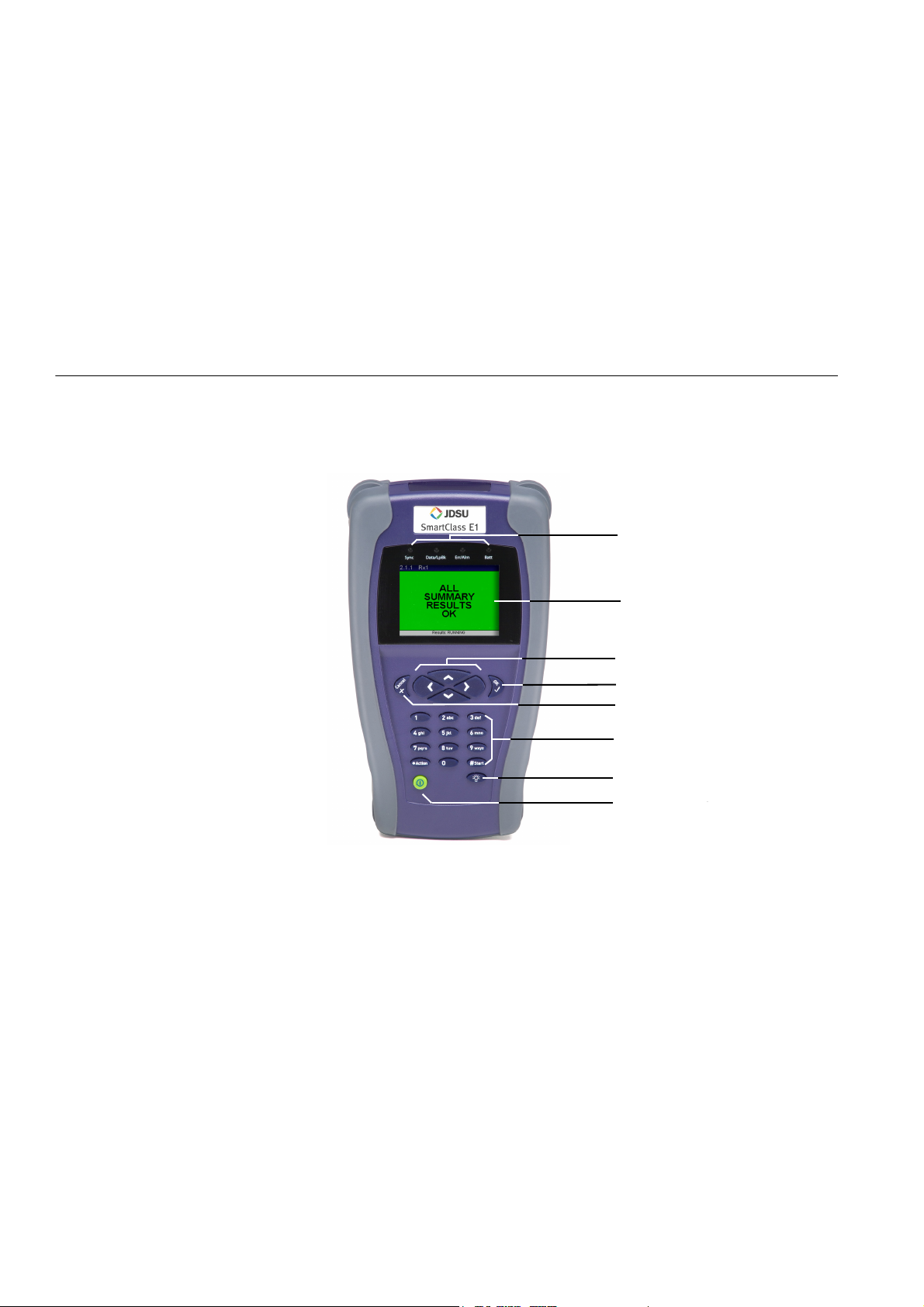
The controls and LEDs on the SmartClass front panel, shown in Figure 1, are
used to operate the unit, set up tests, and view data.
Status LEDs
LCD
Arrow keys
OK key
Cancel key
Keypad
(includes *Action and #Start keys)
Backlight key
Power key
Figure 1 SmartClass front panel
The label near the top will say “SmartClass E1/Data”, if you have the
E1/Datacomm configuration.
The following paragraphs describe each of the controls and LEDs on the front
panel.
6 SmartClass E1 Tester User’s Guide
Page 23

Chapter 1 Getting Started
Exploring the front panel
Status LEDs
These indicators report the status of the unit. The function of the LEDs change
depending on the application. Table 6 describes each of the Status LEDs.
Table 6 Status LEDs
Status LED Description
Sync For E1 testing:
Green
– Solid—A signal is present and synchronization is established
on all active receivers.
– Flashing—Auto-framing is running on at least one active
receiver.
Red
– At least one of the active receivers does not have frame syn-
chronization.
Off
– No signal has been detected on any receiver.
For Datacom testing:
Green
– Solid—A receive clock is present.
Red
– Solid—A receive clock was present at some point in the past,
but was lost.
Off
– No receive clock has been detected on any receiver.
Data/LpBK Green
– Solid—Synchronization is established with BERT pattern for all
active receivers.
– Flashing—Auto-pattern is running on at least one active
receiver.
Red
– At least one of the active receivers does not have pattern syn-
chronization.
Amber
– For E1 testing: The E1 Tester has been placed in a line loop-
back mode.
Off
– The E1 Tester is not in a line loopback mode, which means the
selected traffic pattern is live on all active receivers, or no pat-
tern synchronization has been detected on the receiver.
Err/Alm Red
– Flashing —The LED flashes for one second when an error or
alarm occurs. Or, for E1 testing, flashes when the unit is
searching for framing or a pattern during Auto Config.
Amber
– At least one error or alarm has occurred since that last reset.
Off
– All Summary results are OK. No error or alarm has been
received.
SmartClass E1 Tester User’s Guide 7
Page 24

Chapter 1 Getting Started
Exploring the front panel
Table 6 Status LEDs
Status LED Description
Batt Green
– Solid—An external source is powering the unit.
Red
– Low battery, or the charger has detected a fault condition.
Amber
– The battery is charging.
Off
– A battery is powering the unit.
LCD
Cancel key
OK key
Arrow keys
Keypad
*Action key
The LCD is a 320 x 240 pixel color display with contrast control and backlight.
Use the Cancel key to exit a data entry screen without changing your settings,
or to return to the previous menu.
Use OK to accept a changed setting or to proceed to the next menu.
Use the arrow keys to navigate through menu selections. For E1 testing, when
viewing the test results, use the left or right arrow key to switch between Rx1
and Rx2 result screens. For Datacom testing, in monitor mode use the left or
right arrow to switch between DCE and DTE.
Use the keypad to enter numbers, make menu selections, enter alphabetic
characters, and so on. Throughout the menus, the numbers associated with
each function provide a quick way to perform tests with simple number
sequences.
Use the *Action key to insert errors or alarms during testing.
#Start key
Backlight key
Power key
8 SmartClass E1 Tester User’s Guide
Use the #Start key to restart your test and transmit traffic immediately after you
configure your test. After starting the test, the unit automatically displays test
results associated with your application.
Use the backlight key to adjust the brightness level on your LCD. The SmartClass E1 provides four brightness levels on the LCD. Pressing the backlight
key once increases the brightness by one level. The brightness level returns to
the original level when you press the backlight key the fourth time.
Use the power key to turn power ON (see “Powering ON your unit” on
page 10), put the unit into sleep mode, or turn power OFF (see “Powering OFF
your unit” on page 10).
Page 25
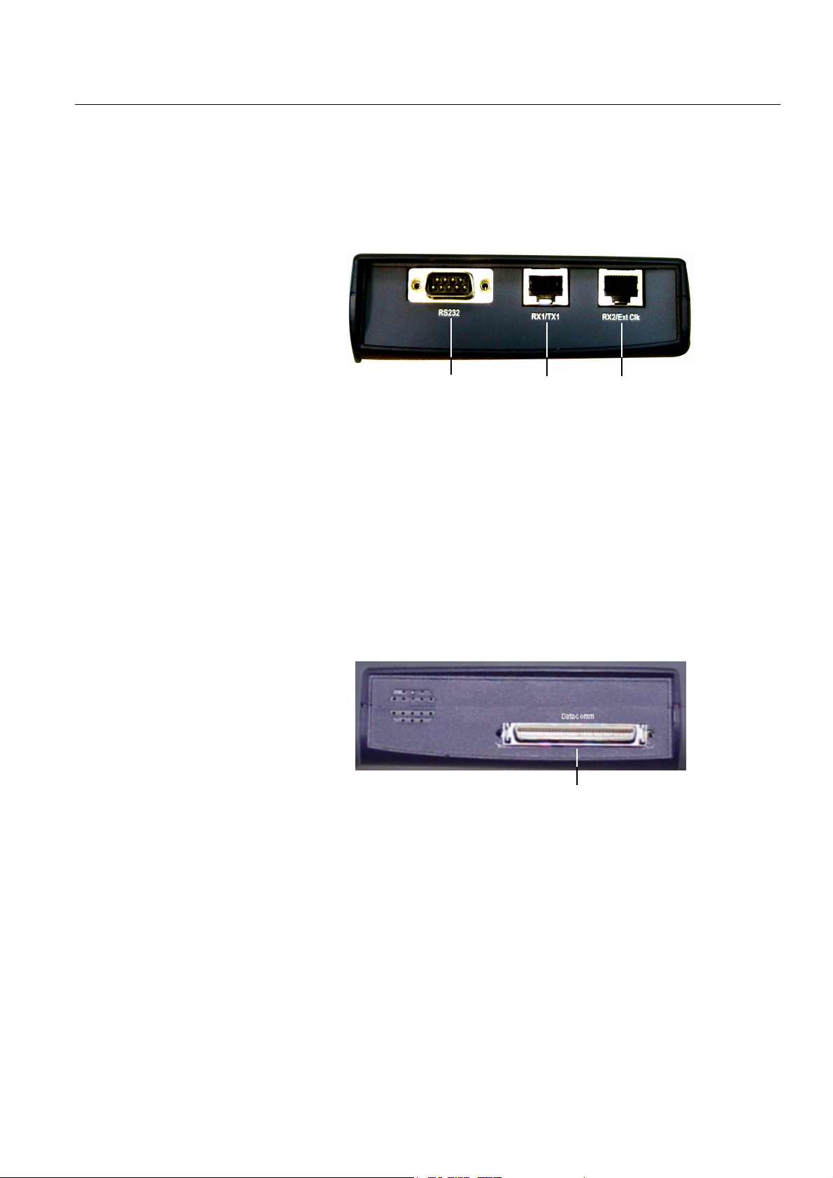
Exploring the side panels
Chapter 1 Getting Started
Exploring the side panels
The connectors located on the side panels are used to connect the E1 Tester
to the circuit for testing.
Left side panel
Right side panel
Figure 2 shows the left side panel.
RS232 Connector
RJ-48 Connectors
Figure 2 SmartClass E1 Tester left side panel
Use the RJ-48 jacks (labeled RX1/TX1 and RX2/Ext Clk) to connect to E1
circuits. See Table 5 on page 4 for cables that are available for the SmartClass
E1 Tester.
The RS232 connector is only used on the SmartClass E1/Datacomm configuration. It is used to connect to network elements when using the optional
VT-100 emulation feature.
The right side panel has a universal connector, shown in Figure 3, that is used
to connect to Datacom circuits
universal connector
Figure 3 SmartClass E1 Tester right side panel
The universal connector supports several interface standards. Use the
connector and adaptor cables (see Table 5 on page 4) to connect to the appropriate test interface. For pin assignments for the supported interface standards, see Appendix A on page 111.
SmartClass E1 Tester User’s Guide 9
Page 26
Chapter 1 Getting Started
Exploring the bottom panel
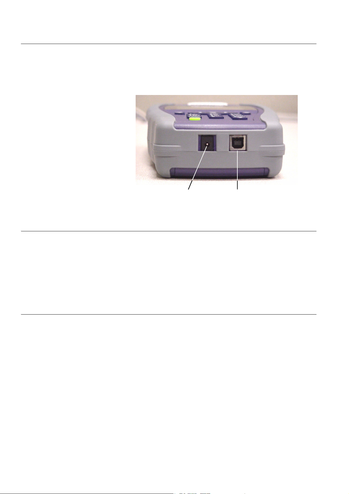
Exploring the bottom panel
The SmartClass AC adapter and USB device ports are located on the bottom
panel. The USB device port is used to establish connections that allow you to
run reports from a remote device (typically a PC or laptop) or update the software using the Download Manager utility.
Powering ON your unit
Powering OFF your unit
USB device portAC adapter port
Figure 4 SmartClass bottom panel
The following procedure describes how to power ON the E1 Tester.
To power ON your unit
– Press and hold the Power key for a few seconds.
The SmartClass E1 splash screen appears for a few seconds, and then the
Main Menu appears.
The following procedure describes how to power OFF the E1 Tester.
To power OFF your unit
1 Press and hold the Power key for a few seconds.
The Power Control menu appears.
2 Do one of the following:
– If you want to be able to restart the unit quickly, select Enter Sleep
Mode. The test stops, and then the user interface disappears. If the
backlight is ON, the unit automatically turns it OFF. When you are
ready to resume testing, press the Power key for a few seconds to
redisplay the user interface.
NOTE: If your unit is in sleep mode for more than two hours, it will automatically turn itself OFF.
10 SmartClass E1 Tester User’s Guide
Page 27
Navigating the user interface
Chapter 1 Getting Started
Navigating the user interface
– To conserve power and completely power OFF your unit, select Shut
Down. A message briefly appears informing you that the unit is shut-
ting down.
Power is OFF.
The user interface of the SmartClass is designed to be intuitive and easy to
use. Using the LCD and keypad, you can set up the unit, configure test parameters, and view test results. This section describes the user interface, and
explains how to navigate through the menus and screens.
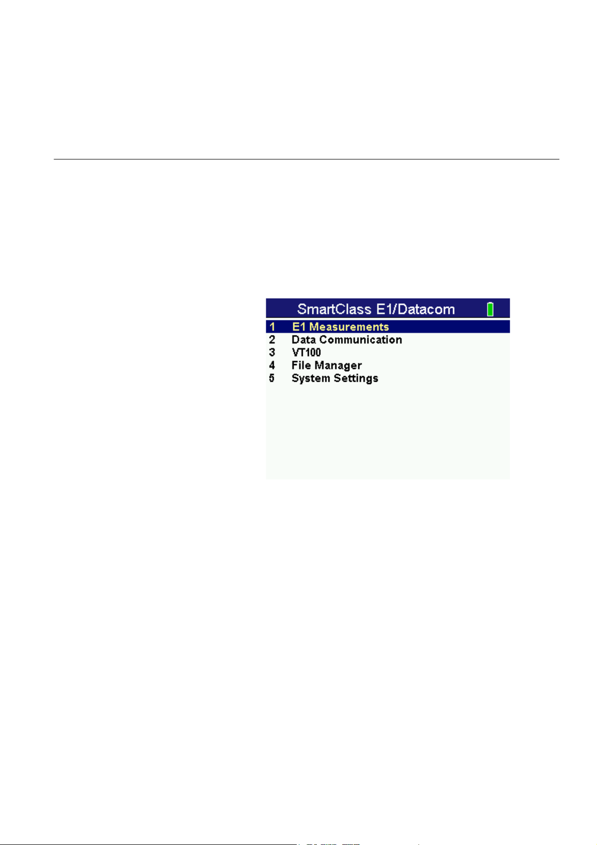
When you power up the SmartClass E1 Tester, the Main Menu of the user
interface appears. Figure 5 illustrates the Main menu for the SmartClass E1/
Datacom tester.
Figure 5 SmartClass E1/Datacom Tester Main Menu
There are 3 types of screens on the user interface:
– Menus
– Data entry screens
– Results screens
SmartClass E1 Tester User’s Guide 11
Page 28
Chapter 1 Getting Started
Navigating the user interface
Menu screens
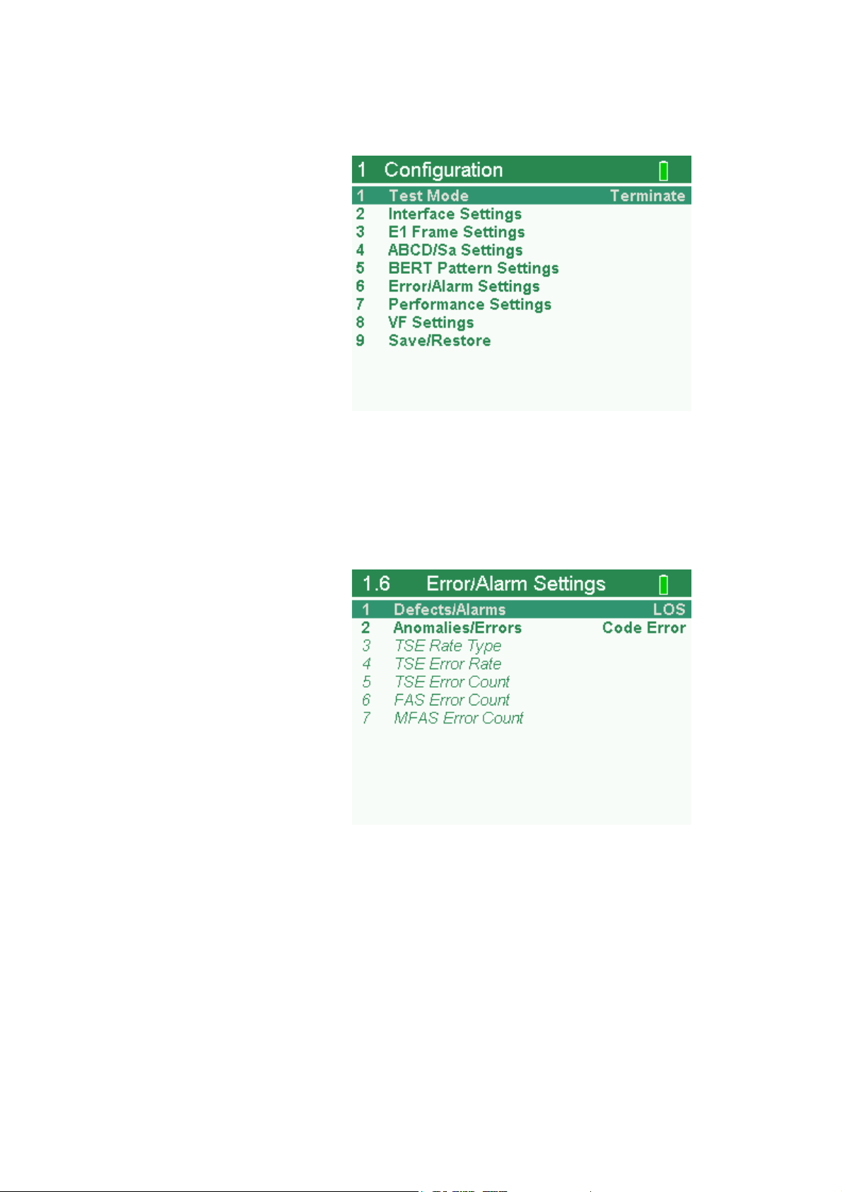
Figure 6 illustrates the Configuration menu screen for the SmartClass E1
tester.
Figure 6 SmartClass E1 Tester Configuration menu screen
Menu screens provide a series of selections that take you to another menu
screen, a data entry screen, or a results screen.
Figure 7 illustrates the Error/Alarm settings menu screen listing each of the
available error or alarm settings.
Figure 7 SmartClass E1 Tester Error/Alarm Settings menu screen
12 SmartClass E1 Tester User’s Guide
Page 29
Chapter 1 Getting Started
Navigating the user interface
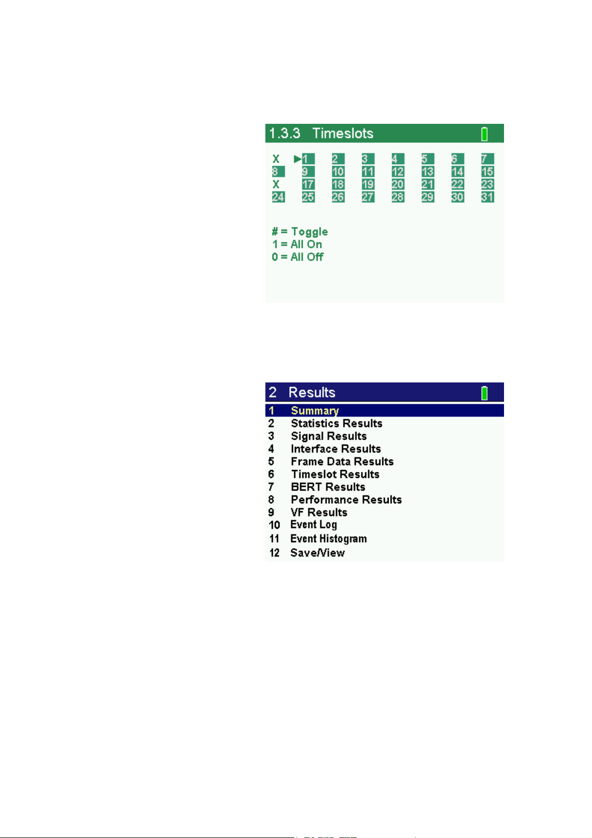
Data entry screens
Result screens
Data entry screens provide a list of selectable options, or allow you to enter
data or specify settings using the keypad. Figure 8 illustrates the Timeslots
screen, used to specify the timeslots you want to use to transmit traffic in.
Figure 8 SmartClass E1 Tester Data Entry screen
Figure 9 illustrates a Result screen.
Figure 9 SmartClass E1 Tester Result screen
These screens display test results. The results are split into categories. Press
the arrow keys to navigate through the result categories (screens).
SmartClass E1 Tester User’s Guide 13
Page 30

Chapter 1 Getting Started
Using the keypad
Using the keypad
Use the keypad to enter alpha-numeric values, or to navigate to different
screens by specifying the menu number corresponding to the screen. When
entering alpha-numeric values for a test setting:
– The left arrow positions the cursor one position to the left.
– The down arrow operates as a Backspace key, and typically clears the
character one position to the left of the cursor. If the cursor is on the first
character of a text entry field, the down arrow deletes the first character.
– If you are entering text, the up arrow serves as a Caps Lock key.
Selecting a menu option or a
configuration setting
Returning to a previous menu
Entering numeric values
There are three ways to select a menu option or configuration setting.
– Use the arrow keys to scroll to the desired option then press the OK key.
– Press the number associated with the menu option.
– Change on/off or enable/disable values using the left and right arrow keys
on your keypad. For example, if the current value is ON, pressing the left
arrow a single time changes the value to OFF. Pressing it a second time
changes it back to ON.
Use the Cancel key to return to the previous menu.
To enter numeric values
1 Use the arrow keys to scroll to and highlight the setting you want to
specify.
2 Press OK.
3 Use the keypad to type the numeric value.
4 If you want to move to the next field, use the right arrow key.
5 If you want to enter a minus sign (-), and the setting accepts negative
values, press the # key.
6 If you want to enter a decimal point, and the setting accepts floating
decimal values, press the asterisk (*) key.
Typing text
14 SmartClass E1 Tester User’s Guide
To type text
1 Use the arrow keys to scroll to and highlight the setting you want to
specify.
2 Press OK.
Page 31

Chapter 1 Getting Started
Using the keypad
3 Use the keypad to type the text.
– Repeatedly pressing a key scrolls through the selections for that key.
For example, repeatedly pressing the 2 key will scroll through A, B, C
and 2.
– To toggle between upper and lower case, press the up arrow.
– To delete the previous character, press the down arrow.
– Use the left and right arrow to navigate through typed text.
– To enter a space between characters, press the 0 (zero) key once.
– To scroll through and select a special character such as:
. @ / , ‘ - ? ! _ 1
press the 1 (one) key.
NOTE
You can not enter a space when specifying a filename.
SmartClass E1 Tester User’s Guide 15
Page 32

Chapter 1 Getting Started
Using the keypad
16 SmartClass E1 Tester User’s Guide
Page 33

Chapter2
Instrument Settings
2
This chapter describes how to configure the basic settings of the instrument.
Topics discussed in this chapter include the following:
– “Setting the language” on page 18
– “Viewing the software and hardware information” on page 18
– “Setting the date and time” on page 19
– “Adjusting the contrast and brightness” on page 20
– “Determining the specified battery type” on page 20
– “Managing files” on page 20
– “Setting options” on page 21
– “Restoring factory defaults” on page 21
SmartClass E1 Tester User’s Guide 17
Page 34

Chapter 2 Instrument Settings
Setting the language
Setting the language
The following instructions explain how to specify the language for your
SmartClass E1Tester.
To specify the language for the SmartClass E1 tester
1 Power ON your tester by pressing and holding the key for a few
seconds.
The SmartClass E1 splash screen appears briefly, and then the
SmartClass E1 main menu appears.
2 Select System Settings. A menu appears listing each of the system
settings.
3 Select Language. A menu appears listing the available languages.
4 Select the language. After a brief moment, the main menu appears, and
options appear in the language you selected.
The language for the E1 Tester is specified.
NOTE:
If you select the wrong language by mistake, you can return to the language
selection menu by selecting the last item on the Main Menu, and then the
last menu on the System Settings menu.
Viewing the software and hardware information
The Version Info screen displays the current version of the software loaded on
your unit, whether your hardware is jitter capable, and the factory-assigned
SCE ID number.
To view the software and hardware information
1 Select System Settings from the Main Menu.
2 Select Version Info.
The software version and SCE ID Number appear. The screen may also
display “Jitter-capable hardware”.
NOTE:
The jitter option requires both newer hardware and an option code. Thus,
having hardware that is jitter capable does not guarantee that the option is
enabled. To verify whether your unit includes the jitter option, view the E1
Measurement menu. If it includes a selection for E1 Jitter, the option is
enabled.
18 SmartClass E1 Tester User’s Guide
Page 35

Setting the date and time
Chapter 2 Instrument Settings
Setting the date and time
The E1 Tester has an internal clock that you can set to provide accurate time
stamps for test results. By default, the clock uses a 12-hour format and
presents dates in a MM/DD/YYYY format. You can optionally configure your
unit to use a 24-hour time format or a DD/MM/YYYY date format. For example,
you can configure the E1 Tester to display midnight, January 15th in the
following manner:
Time format Time displayed Date format Date displayed
Changing the date or time
format
Setting the date or time
12-hour 12:00:00 AM
24-hour 00:00:00 DD/MM/YYYY 15/01/2007
The following procedure describes how to change the date or time format on
your unit.
To change the date or time format
1 Select System Settings from the Main Menu.
2 Select Set Time/Date Format.
3 Do one of the following:
– To change the format used to display the time, select Time Format,
and then select the new format.
– To change the format used to display the date, select Date Format,
and then select the new format.
The format is changed.
The following procedure describes how to set the date or time.
MM/DD/YYYY 01/15/2007
To set the date or time
1 Select System Settings from the Main Menu.
2 Select Set Time/Date.
3 Do one of the following:
– To set the time, select Set Time, and then enter the time.
– To set the date, select Set Date, and then enter the date.
The date or time is set.
SmartClass E1 Tester User’s Guide 19
Page 36

Chapter 2 Instrument Settings
Adjusting the contrast and brightness
Adjusting the contrast and brightness
The following procedure describes how to adjust the contrast and brightness.
To adjust the contrast and brightness
1 Select System Settings from the Main Menu.
2 Select Contrast/Brightness.
3 Change the contrast level using the left or right arrow key.
4 Change the brightness using the up or down arrow key.
5 Press the Cancel key to return to the previous Menu.
The contrast and brightness are set. You can also press and hold the Backlight
key, and then press the right and left arrows to adjust contrast of the display.
Determining the specified battery type
Managing files
The following procedure describes how to determine the type of battery you
specified when you installed batteries in your unit (see “Replacing the
batteries” on page 105).
To determine the specified battery type
1 Select System Settings from the Main Menu.
2 Select Battery Selection.
A screen briefly appears indicating the type of battery you specified, and then
the System Settings menu appears.
The following procedure describes how to view or delete test configuration or
test result files.
To view or delete files
1 Select File Manager from the Main Menu.
The File Manager menu appears.
2 Select Config Files or Result Files.
A list of files appears.
3 Use the down arrow to scroll to the desired file, and then do one of the
following:
– If you want to view the file, press the OK key.
– If you want to delete the file, press the left arrow key.
A menu appears asking you to verify whether or not you want to delete
the file.
To delete the file, select Yes.
The file is deleted.
20 SmartClass E1 Tester User’s Guide
Page 37

Specifying DB9 port usage
The E1 Tester has one DB9 RS232 serial port but both the VT100 and remote
control options use this port. This menu specifies which option will use the port.
This menu only appears if your unit has both options.
To specify the DB9 port usage
1 Select System Settings from the Main Menu.
2 Select RS232 DB9 port usage.
3 Choose which option will use the DB9 port.
The port usage is specified.
Setting options
The Set Options item on the System Settings menu allows you to add optional
functionality to your SmartClass E1 Tester. If the options were ordered at the
same time the unit was ordered, they will be installed at the factory. If you order
a field upgrade, you will receive a package with an option code to enter here,
along with additional instructions.
Chapter 2 Instrument Settings
Specifying DB9 port usage
The default is VT100.
Restoring factory defaults
The following procedure describes how to restore the E1 Tester to use factory
default test application and system settings.
To restore factory default settings
1 Select System Settings from the Main Menu.
2 Select Restore Defaults.
3 Select Yes to restore the settings, or No to keep the current settings.
Factory defaults are restored.
SmartClass E1 Tester User’s Guide 21
Page 38

Chapter 2 Instrument Settings
Restoring factory defaults
22 SmartClass E1 Tester User’s Guide
Page 39

Chapter3
Basic Testing
3
This chapter provides instructions for basic tests or procedures that are
common among testing applications. Topics discussed in this chapter include
the following:
– “Managing test configurations” on page 24
– “Starting or restarting a test” on page 25
– “Stopping a test” on page 25
– “Timed testing” on page 25
SmartClass E1 Tester User’s Guide 23
Page 40

Chapter 3 Basic Testing
Managing test configurations
Managing test configurations
After specifying test settings, you can save the configuration, and then restore
it at a later time when you want to run a test using the same settings. You can
also view a stored test configuration to verify it matches the desired settings
before using it. If you no longer need the configuration, you can delete it.
Saving a configuration
Restoring a configuration
To save a test configuration
1 If you haven’t already done so, launch your test application (see
“Launching an E1 test application” on page 28), and configure the test
(see “Specifying test application settings” on page 29).
2 On the Configuration menu, select Save/Restore-View.
A menu appears.
3 Select Save Config.
A screen appears prompting you for a filename for the configuration file.
4 Enter a filename, and then press OK.
The configuration file is saved.
To restore a saved test configuration
1 On the Configuration menu, select Save/Restore-View.
A menu appears.
2 Select Restore/View.
A menu appears listing all saved configurations.
3 Use the up and down arrows to highlight the configuration you want to
restore, and then the right arrow.
Viewing a configuration
The configuration is restored.
To view a saved test configuration
1 On the Configuration menu, select Save/Restore-View.
A menu appears.
2 Select Restore/View.
A menu appears listing all saved configurations.
3 Use the up and down arrows to highlight the configuration you want to
restore, and then press OK.
The configuration is displayed on the screen.
24 SmartClass E1 Tester User’s Guide
Page 41

Starting or restarting a test
Chapter 3 Basic Testing
Starting or restarting a test
After you configure your test, you are ready to start or restart the test.
To start or restart the test
1 If you haven’t already done so, launch your test application (see
“Launching an E1 test application” on page 28 or “Launching the datacom
application” on page 52), and configure the test (see “Specifying test application settings” on page 29 or page 53).
2 Press the # Start key.
The unit clears your test results, the test restarts, and the unit transmits the
traffic you configured.
The test starts or restarts.
NOTE
You can also start or restart a test by pressing the Cancel key until you get
to the BERT menu, and then select Action, and then selecting the corresponding option on the Action menu.
Stopping a test
Timed testing
You can stop a test any time.
To stop a test
1 Press Cancel until you get to the main test menu, and then select Action.
A menu of actions applicable to you test appears.
2 Select Stop Test.
A message appears indicating the tester is stopping the test.
The test stops.
If you wish to run a test for a specific amount of time, you can do a timed test.
To do a timed test
1 If you haven’t already done so, launch your test application (see
“Launching an E1 test application” on page 28 or “Launching the datacom
application” on page 52), and configure the test (see “Specifying test application settings” on page 29 or page 53).
2 On the Configuration menu, select Timed Test.
3 Select Enabled, and then select either On or Off.
4 Select Duration, and then enter the number of seconds to run the test.
The test runs for the specified duration.
SmartClass E1 Tester User’s Guide 25
Page 42

Chapter 3 Basic Testing
Viewing test results
Viewing test results
After the E1 tester is connected to the circuit and test is started, the unit immediately accumulates and displays results in the Summary and Signal result
categories. After you start a test and transmit traffic, additional test results
populate the remaining categories.
To view test results
1 If you haven’t already done so, launch a test application (see “Launching
an E1 test application” on page 28 or “Launching the datacom application”
on page 52).
2 Start the test.
3 On the Main menu for the test, select Results.
A menu of result categories applicable to you test appears.
4 Select a result category.
5 If necessary, use the up / down arrow keys or the OK key to select Rx1 or
Rx2 results.
Remote Control
Test results appear for the category you selected. After the test is complete
and all results have accumulated, the status bar at the bottom of the results
display blinks and indicates that the results are complete.
You can clear existing result values and then accumulate new values using the
Restart action.
The test results for the category appear. For descriptions of test results, see
Chapter 7 “Test Results”.
With the remote control option, you can connect to a E1 Tester in order to
control it remotely using command lines via the serial interface. A command
guide is available with the option.
26 SmartClass E1 Tester User’s Guide
Page 43

Chapter4
E1 Testing
4
This chapter provides task-based instructions for turning up and troubleshooting E1 service using the SmartClass E1 Tester. Topics discussed in this
chapter include the following:
– “About E1 testing” on page 28
– “Launching an E1 test application” on page 28
– “Specifying test application settings” on page 29
– “Monitoring a circuit” on page 38
– “Measuring timing slips” on page 39
– “Terminate testing” on page 40
– “Line loopback testing” on page 41
– “Pulse shape analysis” on page 42
– “Measuring Jitter” on page 43
– “Testing MFC-R2 Signaling” on page 46
SmartClass E1 Tester User’s Guide 27
Page 44

Chapter 4 E1 Testing
About E1 testing
About E1 testing
The SmartClass E1 tester is intended to be used to commission and maintain
E1 circuits. Typically this involves out-of-service testing to ensure that the
physical layer is clean and there are no problems with network equipment or
improper provisioning.
You can use the SmartClass E1 in the following ways:
– To terminate a circuit, and then loop back to another SmartClass unit or
piece of network equipment to perform BER testing.
– To perform BER analysis end-to-end between two SmartClass units (typi-
cally requires two technicians) with analysis performed in both directions.
This allows you to easily isolate faults on the circuit.
– To passively monitor one or two E1 circuits (in-service testing) by exam-
ining transmission layer metrics such as CRC and frame errors or timing
slips.
– To perform BER testing on individual timeslots within an E1 circuit.
– To perform line loopback testing to monitor the circuit.
– To measure an E1 pulse and display a graph of the pulse shape
Launching an E1 test application
The following procedure describes how to launch an E1 test.
To launch an E1 test
1 Power ON your tester by pressing and holding the key for a few
seconds.
The SmartClass E1 splash screen appears for a few seconds, and then
the SmartClass E1 main menu appears.
2 Select E1 Measurements. The E1 Measurements menu appears.
3 Select an application; for example, E1 BERT.
A message briefly appears stating that the unit is launching the test application.
A test menu appears for the application, listing the following options:
– Configuration. Select this option to configure your test.
– Results. Select this option to observe test results associated with your
test.
– Error/Alarm. Select this option to insert errors or alarms as you test.
This is only available in the E1 BERT application.
– Action. Select this option to perform key actions required for your test,
such as starting or restarting a test, starting traffic or looping up a unit.
You can also press the Action button at any time to view a menu of
actions applicable to your test.
The E1 test application is launched.
28 SmartClass E1 Tester User’s Guide
Page 45

Specifying test application settings
Before transmitting traffic over a link, you can specify interfaces and settings
that filter received traffic for analysis.
Chapter 4 E1 Testing
Specifying test application settings
Specifying a test mode
The SmartClass E1 can operate in the following test modes:
– Terminate Mode: This mode separates the Transmit and Receive side of
an E1 path. The received E1 signal is terminated and a completely independent signal is transmitted.
Use this mode to test out of service lines using the RX1/TX1 port. You can
generate and send test patterns on TX1 and receive patterns on RX1.
RX2/Ext Clk is not used in this mode.
– Monitor Mode (PMP Monitor): This mode measures signal parameters
and monitors traffic at an E1 access point (the PMP – Protected Monitor
Point). The PMP typically has a resistive loss of -26dB. The tester applies
gain to the input signal to compensate for the reduced PMP amplitude.
Both of the receivers are monitored simultaneously. However, the E1
tester does not transmit any traffic in this mode. This permits simultaneous
non-intrusive monitoring of the E1 line.
– Bridge Mode (HI-Z Monitor): This mode allows you to bridge onto a
terminated E1 line with a high impedance (Hi-Z). This permits simultaneous non-intrusive monitoring on the E1 line. The transmitter on the E1
line is not used in this mode.
– Line Loopback: This mode loops the entire E1 circuit. This configuration
will loop the incoming data back out the transmitter yet still allow the
receiver to monitor the incoming signal.
Table 7 lists the transmitter/receiver used in the test modes supported by the
SmartClass E1 tester:
Table 7 SmartClass E1 Tester Test Modes
Test Mode Rx1 Tx1 Rx2 Rx1 VF
Terminate X X X
Monitor X X X
Bridge X X X
Line Loopback X X X
To specify a test mode
1 If you haven’t already done so, launch an E1 application (see “Launching
an E1 test application” on page 28).
2 On the Configuration menu, select Test Mode, and then use the up or
down arrow to specify one of the following:
– Terminate
–Monitor
– Bridge
– Line Loopback
SmartClass E1 Tester User’s Guide 29
Page 46

Chapter 4 E1 Testing
Specifying test application settings
3 If you need to specify other settings for the test, press Cancel to return to
the Configuration menu.
The test mode is specified.
Configuring test settings
automatically
You can use the Auto Configure feature to configure the interface, framing, and
pattern settings automatically.
To configure the interface, framing, and pattern settings automatically
1 If you haven’t already done so, launch your test application (see
“Launching an E1 test application” on page 28).
2 Connect the E1Tester to the circuit.
3 On the test menu, select Action.
The Action menu appears.
4 On the Action menu, select Auto Configure.
The SmartClass E1 will attempt to automatically configure the interface,
framing, and pattern. If this attempt fails, the E1 tester will set the framing
to Unframed and the pattern to Live. You can also configure the framing
and pattern settings manually. See “Specifying E1 framing settings” on
page 31 and “Specifying a BERT pattern” on page 33.
The interface, framing, and pattern settings are automatically configured.
Proceed to configure the following settings for the test:
– VF settings, see “Specifying VF settings” on page 37.
– E1 signaling settings, see “Specifying E1 signaling (ABCD/Sa) settings” on
page 32.
– Defect and anomaly settings, see “Specifying Error/Alarm settings” on
page 35.
– Performance settings, see “Specifying performance settings” on page 36.
Specifying interface settings
Before you transmit E1 traffic, you can specify the characteristics of the interface you want to transmit the traffic on, such as the line coding for the signal
you want to transmit, the transmit clock, and the slip reference for the receiver.
To specify interface settings
1 If you haven’t already done so, launch an E1 BERT application (see
“Launching an E1 test application” on page 28).
2 On the Configuration menu, select Interface Settings, and then specify
values for the following settings:
Setting Parameter
Line Coding Select one of the following line coding
options:
– HDB3: High Density Bipolar 3
– AMI: Alternate mark inversion
30 SmartClass E1 Tester User’s Guide
Page 47

Chapter 4 E1 Testing
Specifying test application settings
Setting Parameter
Tx Clock Select one of the following:
– Internal
– Rx1
– Rx2
– Ext. BNC
NOTE: If timing is lost, the SmartClass reverts
to internal timing.
Tx Clk Offset (ppm) Enter a value, from -100 through 100 ppm, to
indicate the offset frequency generated by the
2048 kbit/s internal clock.
To specify negative numbers, press the # key.
To delete a single character, press the down
arrow key.
Slip Reference Select one of the following slip reference
options:
– Rx2
– Ext. BNC
Specifying E1 framing
settings
3 If you need to specify other settings for the test, press Cancel to return to
the Configuration menu.
The interface settings are configured.
Before transmitting E1 traffic, you can specify the framing format and payload
of the traffic you want to transmit.
To specify E1 framing settings
1 If you haven’t already done so, launch an E1 application (see “Launching
an E1 test application” on page 28).
2 On the Configuration menu, select E1 Frame Settings, and then specify
values for the settings listed below:
Setting Parameter
Framing Select the framing format for the signal:
– PCM31C
– PCM31
– PCM30C
– PCM30
– Unframed
Payload Select the payload:
– Bulk: full E1 circuit
– nx64k: individual timeslot(s) from an E1
circuit
SmartClass E1 Tester User’s Guide 31
Page 48

Chapter 4 E1 Testing
Specifying test application settings
Setting Parameter
Timeslots
nx64k payload only)
(
Idle Byte
nx64k payload only)
(
Do one of the following:
– To turn all the available channels on,
press 1.
– To turn all the available channels off,
press 0.
– To turn on only the selected channels, use
the arrow keys to point at the channels
you want to turn on, and then press the #
key to select the channel. You can select
multiple channels.
When you have finished selecting timeslots,
press OK. At least one timeslot must be
selected.
Specify the idle byte pattern you want to insert
into the selected timeslots.
For example, (MSB) 10101010 (LSB), the
MSB is sent first.
3 If you need to specify other settings for the test, press Cancel to return to
the Configuration menu.
The framing settings are configured.
Specifying E1 signaling
(ABCD/Sa) settings
Before transmitting E1 traffic, you can specify settings for E1 signaling.
To specify E1 signaling settings
1 If you haven’t already done so, launch an E1 test application (see
“Launching an E1 test application” on page 28).
2 On the Configuration menu, select ABCD/Sa Settings, and then specify
values for the following settings:
Setting Parameters
Sa4 Set the 8-digit Sa4 bit sequence.
Sa5 Set the 8-digit Sa5 bit sequence.
Sa6 Set the 8-digit Sa6 bit sequence.
Sa7 Set the 8-digit Sa7 bit sequence.
Sa8 Set the 8-digit Sa8 bit sequence.
A Bit (Remote Alarm) Select whether the NFAS A Bit is On or Off.
Si Bit Select whether the Si Bit is ITU-T (default) or USER.
Signaling Bits (BERT) Set the 4-digit active signaling word.
Signaling Bits (Idle) Set the 4-digit idle signaling word.
NMFAS (XYXX) Set the 4-digit NMFAS word.
3 If you need to specify other settings for the test, press Cancel to return to
the Configuration menu.
The E1 signaling settings are configured.
32 SmartClass E1 Tester User’s Guide
Page 49

Chapter 4 E1 Testing
Specifying test application settings
Specifying a BERT pattern
You can specify a BERT pattern for your test.
To specify a BERT pattern
1 If you haven’t already done so, launch an E1 test application (see
“Launching an E1 test application” on page 28).
2 On the Configuration menu, select BERT Pattern Settings, and then
select Pattern.
3 Select one of the following BERT patterns:
Pattern Description
63 (2^6-1) Selects the 2
erates a maximum of 5 sequential 0s and 6 sequential 1s.
511 (2^9-1) Selects the 2
erates a maximum of 8 sequential 0s and 9 sequential 1s.
2047 (2^11-1) Simulates live E1 data. A pseudorandom pattern
based on an 11-bit shift register. Selects the 2
Pseudorandom pattern, which generates a maximum
of 10 sequential 0s and 11 sequential 1s.
2^15-1 ITU Selects the 2
erates a maximum of 14 sequential 0s and 15
sequential 1s. Simulates live data for 56 kbit/s to 2
Mbit/s circuits. This is the default pattern for E1.
2^15-1 INV ITU Selects the inverted 2
which generates a maximum of 14 sequential 1s and
15 sequential 0s.
6
-1 pseudorandom pattern, which gen-
9
-1 pseudorandom pattern, which gen-
11
15
-1 pseudorandom pattern, which gen-
15
-1 pseudorandom pattern,
-1
2^20-1 Selects the 220 -1 pseudorandom pattern, which gen-
erates a maximum of 19 sequential 0s and 20
sequential 1s.
20
2^20-1INV Selects the inverted 2
-1 pseudorandom pattern,
which generates a maximum of 19 sequential 1s and
20 sequential 0s.
23
2^23-1 ITU Selects the 2
-1 pseudorandom pattern, which generates a maximum of 22 sequential 0s and 23
sequential 1s.
23
2^23-1 INV ITU Selects the inverted 2
-1 pseudorandom pattern,
which generates a maximum of 22 sequential 1s and
23 sequential 0s.
Delay Used for measuring round trip delay. Delay pattern
measurement requires a transmitter/receiver loopback, with the transmit rate equal to the receive rate.
This test measures round trip delay once per second
(or until the previous delay measurement is complete) for the length of the test, provided pattern sync
is present. Normal BER test results (such as bit
errors and pattern sync) are not available during
delay testing
20
QRSS Simulates live E1 data. E1 QRSS is a modified 2
pseudorandom pattern that allows a maximum of 15
sequential zeros and 20 sequential ones. 2
20
-1
-1 pseu-
dorandom pattern with 14-zero suppression.
SmartClass E1 Tester User’s Guide 33
Page 50

Chapter 4 E1 Testing
Specifying test application settings
Pattern Description
All Ones Provides a fixed test pattern of all ones (AMI pulses).
It can be used as an AIS in unframed circuits, a keep
alive signal, or an idle code. This pattern is required
to accurately measure the E1 signal power in
dBnom.
All Zeros Provides a fixed test pattern of all ones. The Line
Code should be set for HDB3 when sending the All
Zeros pattern or the network will lose timing. This
pattern can be transmitted framed or unframed.
QBF The Quick Brown Fox message (all uppercase: THE
QUICK BROWN FOX JUMPS OVER THE LAZY
DOG 0123456789).
NOTE: For Datacom testing, this pattern is only available when testing in synchronous mode.
QBF1 The Quick Brown Fox message (see “QBF”) followed
by CR LF.
NOTE: This pattern is only available for Datacom
testing and when testing in asynchronous mode. The
QBF message is encoded according to the number
of data bits you specified in the character format.
QBF2 The Quick Brown Fox message (see “QBF”) followed
by LF CR LF CR.
NOTE: This pattern is only available for Datacom
testing and when testing in asynchronous mode. The
QBF message is encoded according to the number
of data bits you specified in the character format.
QBF3 The Quick Brown Fox message (see “QBF”) followed
by LF CR.
NOTE: This pattern is only available for Datacom
testing and when testing in asynchronous mode. The
QBF message is encoded according to the number
of data bits you specified in the character format.
1:1 A one followed by a zero, the minimum stress on
clock recovery circuits.
1:3 A one followed by 3 zeros.
1:4 A one followed by 4 zeros.
1:7 A one followed by 7 zeroes. Stresses the minimum
ones density requirement for E1 circuits using AMI
coding. This pattern is used to test timing clock
recovery and can be transmitted framed and
unframed.
Live Used in monitor mode to avoid false “errors” when
the monitored circuit contains live traffic rather than
BERT patterns.
User Bit Pattern Selects a user-defined pattern from 3 to 32 bits long.
User Byte Pattern Selects a user-defined pattern from 1 to 64 bytes
long.
If you selected User Bit Pattern or User Byte Pattern, proceed to step 4.
Otherwise, proceed to step 5.
34 SmartClass E1 Tester User’s Guide
Page 51

Chapter 4 E1 Testing
Specifying test application settings
4 Do one of the following:
– If you selected User Bit Pattern, in the BERT Pattern Settings menu,
select User Bit Pattern, and then specify the bit pattern you want to
use.
– If you selected User Byte Pattern, in the BERT Pattern Settings menu,
select User Byte Pattern, and then specify the byte pattern you want
to use.
5 If you need to specify other settings for the test, press Cancel to return to
the Configuration menu.
The BERT pattern is specified.
Specifying Error/Alarm
settings
You can specify the error or alarm to be inserted into the traffic you are transmitting.This is only available in the E1 BERT application.
To specify defects or anomalies
1 If you haven’t already done so, launch the E1 BERT application (see
“Launching an E1 test application” on page 28).
2 On the Error/Alarm menu, select Error/Alarm Settings, and then do one
of the following:
– To specify defects or alarms, select Defects/Alarms, and then proceed
to step 3.
– To specify anomalies or errors, select Anomalies/Errors, and then
proceed to step 4.
3 On the Defects/Alarms menu, select one of the following defects or
alarms:
Defect/Alarm Description
LOS Loss of signal
LOF Loss of framing
AIS Alarm indication signal
RDI Remote defect indication
MF AIS Multi frame AIS
MF RDI Multi frame RDI
Proceed to step 5.
SmartClass E1 Tester User’s Guide 35
Page 52

Chapter 4 E1 Testing
Specifying test application settings
4 On the Anomalies/Errors menu, select one of the following anomalies or
errors:
Anomalies/Errors Description/Additional Settings
TSE Test Sequence Errors (bit error).
If you selected TSE, on the Error/Alarm Settings menu,
select TSE Rate Type, and then select one of the following:
Single.
Multiple. Select TSE Error Count, and then specify
the number of TSE error count (1~50).
Rate. Select TSE Error Rate, and then specify one of
the following:
– 1e-2
– 1e-3
– 1e-4
– 1e-5
– 1e-6
– 1e-7
Specifying performance
settings
Pattern Slip One or more bits of the test pattern are deleted or
repeated
Code Error Violation of the selected encoding method
CRC Error Cyclical redundancy check error
FAS Errors Frame alignment signal error.
On the Error/Alarm Settings menu, select FAS
Error Count, and then specify the number of
FAS error count (1~4).
MFAS Error Multi frame alignment signal error.
On the Error/Alarm Settings menu, select MFAS Error
Count, and then specify the number of MFAS error
count (1~2).
E-bit Error Remote CRC errors
5 If you need to specify other settings for the test, press Cancel to return to
the Configuration menu.
The defect or anomaly settings are configured.
You can configure settings for ITU performance analysis. This is only available
in the E1 BERT application.
To configure performance settings
1 If you haven’t already done so, launch an E1 BERT test application (see
“Launching an E1 test application” on page 28).
36 SmartClass E1 Tester User’s Guide
Page 53

Chapter 4 E1 Testing
Specifying test application settings
2 On the Configuration menu, select Perf. Settings, and then specify values
for the settings listed below:
Setting Parameters
Perf. Spec Select the performance specification:
– G.821
– G.826
– M.2100
Path Allocation Enter a value, from 0.0% to 100%, to indicate the
percentage of the end-to-end target values that
must be met for the test path to be acceptable.
The end-to-end target values are based on the
“Hypothetical Reference Configuration” (HRX) of
length 27,500 km.
Specifying VF settings
UAS Limit Enable (G.826
and M.2100 only)
UAS Limit
(G.826 and M.2100 only)
Select whether the Unavailable Seconds limit is
Enabled (On) or not (Off).
If UAS Limit Enable is On, specify the number of
seconds, between 10 and 100000.
3 If you need to specify other settings for the test, press Cancel to return to
the Configuration menu.
The performance settings are configured.
You can specify the VF tone pattern as the signal you want to transmit, and the
VF timeslot for the receiver. You can also turn the speaker on or off and adjust
the speaker volume. This is only available in the E1 BERT application.
To specify VF settings
1 If you haven’t already done so, launch the E1 BERT test application (see
“Launching an E1 test application” on page 28).
2 On the Configuration menu, select VF Settings, and then specify values
for the following settings:
Setting Parameters
VF Timeslot Do the following:
a To select a timeslot, use the arrow
keys to point at the timeslot, and
then press the # key.
b After you finish selecting the
timeslot, press OK to return to the
VF Settings menu.
VF Tones Specify the VF tones pattern for the
signal you want to transmit.
Speaker State Specify whether the speaker is
turned on or off.
Volume Control Use the right or left arrow keys to
increase or decrease the speaker
volume.
SmartClass E1 Tester User’s Guide 37
Page 54

Chapter 4 E1 Testing
Monitoring a circuit
Monitoring a circuit
3 If you need to specify other settings for the test, press Cancel to return to
the Configuration menu.
The VF settings are configured.
The SmartClass E1 allows you to monitor both E1 receivers simultaneously.
You can analyze full E1 and n x 64k circuits and examine transmission layer
results, such as CRC and frame errors, or code errors for a single side of the
traffic or in both directions.
The following procedure describes how to monitor a circuit.
NOTE:
The transmitter (Tx) is turned off in Monitor mode.
To monitor a circuit
1 Launch the BERT application. See “Launching an E1 test application” on
page 28.
2 Connect the E1 Tester to the test access point:
– Connect the 2M Reference Clock cable from the SmartClass E1 RX2/
Ext Clk jack to an E1 BITS clock or a known good reference signal.
– Connect a cable from the SmartClass E1 RX1/TX1 jack to the signal to
be tested.
3 To set the test configuration, do one of the following:
– On the test menu, select Action, and then select Auto Configure.
The unit will attempt to automatically configure the interface, framing,
and pattern. Go to step 9.
– On the test menu, select Configuration, and then proceed with step 4.
4 On the Configuration menu, select Test Mode.
A list of test modes appears.
5 Select Monitor.
6 Configure the interface settings. See “Specifying interface settings” on
page 30.
7 Configure the Framing settings. If you selected the n x 64k payload, you
can select specific timeslots to monitor. See “Specifying E1 framing
settings” on page 31.
8 Specify a BERT pattern. See “Specifying a BERT pattern” on page 33.
NOTE:
If you select the All Zeros BERT pattern, the line coding should be set to
HDB3. Using AMI is not recommended because the network will lose timing
and signal. To change the line coding see “Line Coding” on page 30.
9 To monitor VF channel, configure the VF settings. See “Specifying VF
settings” on page 37.
10 To configure settings for ITU performance analysis, configure the perfor-
mance settings. See “Specifying performance settings” on page 36.
38 SmartClass E1 Tester User’s Guide
Page 55

Measuring timing slips
Chapter 4 E1 Testing
Measuring timing slips
11 Restart the test.
12 To view other results, see “E1 Results” on page 78.
You have finished monitoring the circuit.
The SmartClass E1 allows you to monitor the timing between two E1 signals
for timing slips. For example, you can check customer premises equipment
against a master clock at the central office, or you can compare two lines of
network equipment. The SmartClass measures the difference, in bits per
second (bit/s), between the opposite receiver (Rx) or the external 2M Reference clock.
The following procedure describes how to measure timing slips.
To measure timing slips
1 Launch the E1 BERT application. See “Launching an E1 test application”
on page 28.
2 On the Configuration menu, select Test Mode.
A list of test modes appears.
3 Select Monitor.
4 Connect the E1 Tester to a reference signal and to the test signal:
– Connect the 2M Reference Clock cable from the E1 Tester’s RX2/
Ext Clk jack to an E1 BITS clock or a known good reference signal.
– Connect a cable from the E1 Tester RX1/TX1 jack to the signal to be
tested.
5 On the Configuration menu, select Interface Settings.
6 Select Slip Reference and then select the clock reference for timing slips.
See “Slip Reference” on page 31.
7 Restart the test.
This will clear all alarms and begin a new test.
8 On the test menu, select Results, and then select Signal Results.
The Signal Results window appears.
9 Check the timing slips result.
For a description of the result, see “Timing Slips” on page 80.
You have finished measuring timing slips.
SmartClass E1 Tester User’s Guide 39
Page 56

Chapter 4 E1 Testing
Terminate testing
Terminate testing
In Terminate mode, you can use the SmartClass E1 to perform bit error rate
testing (BERT or BER testing) on E1 circuits, and timeslots within the E1
circuit. You can test for bit errors, code errors, frame errors, and CRC errors (if
applicable).
In Terminate mode, it is assumed that there is either a far-end loopback or
another test set terminating the far end. This allows you to qualify E1 circuit
error performance by testing for bit errors, code errors, CRC errors, FAS
errors, MFAS errors, and E-BIT errors (if applicable) on E1 lines.
The following procedure describes how to perform a BER test.
To perform a BER test
1 Launch the BERT application. See “Launching an E1 test application” on
page 28.
2 On the Configuration menu, select Test Mode.
A list of test modes appears.
3 Select Terminate.
4 If you are performing an end-to-end test, you can connect a test set at
each end, or you can connect a single test set at the near end and establish a physical loop on the far end device.
For this test, use only the RX/TX1 connector.
5 To configure the test, do one of the following:
– If you want the E1 Tester to configure the interface, framing, and
pattern settings automatically, on the test menu, select Action, and
then select Auto Configure.
The unit will attempt to automatically configure the interface, framing,
and pattern. If the Auto Configure succeeds, proceed to step 8.
If this attempt fails, the E1 Tester will continue it’s attempt to configure
the framing settings, and the pattern will default to Live. You can also
configure the setting manually by selecting Configuration, and then
proceed with step 6.
– If you want to configure the interface, framing, and pattern settings
manually, on the test menu, select Configuration, and then proceed
with step 6.
6 Configure the interface settings. See “Specifying interface settings” on
page 30.
7 Specify the following settings for the test:
–Framing, see “Specifying E1 framing settings” on page 31.
– Pattern, see “Specifying a BERT pattern” on page 33.
– Performance settings, see “Specifying performance settings” on
page 36.
8 Configure the E1 ABCD/Sa settings. See “Specifying E1 signaling (ABCD/
Sa) settings” on page 32.
9 Configure the defect or anomaly settings. See “Specifying Error/Alarm
settings” on page 35.
40 SmartClass E1 Tester User’s Guide
Page 57

Chapter 4 E1 Testing
Line loopback testing
10 Restart the test.
This will clear all alarms/defects and begin a new test.
11 To insert defects or anomalies, press the Action key, and then select the
anomaly or defect. The selections depend on your selection on the Error
Settings menu.
NOTE:
The SmartClass E1 Tester will first attempt to insert a clean code error (without a bit error). If, after a time-out period of 256 bits, this is not possible, the
unit will insert a code plus a bit error (a line error). This timeout would occur
if an unframed all zeros pattern is currently being transmitted.
12 If the circuit is physically looped back, check to see that the inserted errors
are received in the Summary test result category (For instructions on
viewing results, see “E1 Results” on page 78). If you are performing an
end-to-end test, verify that the SmartClass E1 units at each end of the
circuit received the inserted errors.
BER testing is complete.
Line loopback testing
Line loopback testing allows you to loop the entire E1 circuit. This configuration
will loop the incoming data back out the transmitter yet still allow the receiver
to monitor the incoming signal. Line code errors will not be corrected, jitter will
not be cleaned up, and the signal will be regenerated but data will not be
inserted on the line. While in this mode, the E1 Tester will present minimal
delay. You must use the RX1/TX1 port for Line Loopback testing.
The following procedure describes how to perform a line loopback test.
To perform a line loopback test
1 Launch the E1 BERT application. See “Launching an E1 test application”
on page 28.
2 On the test menu, select Configuration.
The Configuration menu appears.
3 On the Configuration menu, select Test Modes.
A list of test modes appears.
4 Select
Line Loopback.
5 Connect the E1 Tester to the test access point, using the RX/TX1
connector.
6 Restart the test.
This will clear all alarms and begin a new test.
7 To view results, see “E1 Results” on page 78.
Line loopback testing is complete.
SmartClass E1 Tester User’s Guide 41
Page 58

Chapter 4 E1 Testing
Pulse shape analysis
Pulse shape analysis
You can use the Pulse Shape feature to measure the height, width, rise time,
fall time, overshoot and undershoot, and signal level of an E1 pulse. The
results are displayed as text or as a graph of the pulse shape. You can also
measure the pulse for conformance to ITU G.703 specifications.
NOTE:
Pulse Shape is an optional feature. It only appears if you have purchased
the pulse shape software option.
To perform pulse shape analysis
1 If you haven’t already done so, launch the E1 Pulse Shape test application
(see “Launching an E1 test application” on page 28).
2 From the E1 Pulse Shape menu, select Configuration.
The Configuration menu appears.
3 Connect the E1 Tester to the test access point, using the RX/TX1
connector.
4 To configure the test, do one of the following:
– If you want the E1 Tester tester to configure the interface, framing, and
pattern settings automatically, on the test menu, select Action, and
then select Auto Configure.
The unit will attempt to automatically configure the interface, framing,
and pattern. If the Auto Configure succeeds, proceed to step 7.
If this attempt fails, the E1 Tester will continue it’s attempt to configure
the framing settings, and the pattern will default to Live. You can also
configure the setting manually by selecting Configuration, and then
proceed with step 5.
– If you want to configure the interface, framing, and pattern settings
manually, on the test menu, select Configuration, and then proceed
with step 5.
5 Configure the interface settings. See “Specifying interface settings” on
page 30.
6 Configure the E1 framing settings. See “Specifying E1 framing settings” on
page 31.
7 Configure the E1 ABCD/Sa settings. See “Specifying E1 signaling (ABCD/
Sa) settings” on page 32.
8 From the E1 Pulse Shape menu, select Results and then select one of the
following:
– Summary displays a large “All Summary Results OK” message if no
anomalies or defects have been detected. If anomalies are detected,
results are displayed.
– Pulse Shape displays a graphical representation of the pulse.
42 SmartClass E1 Tester User’s Guide
Page 59

Chapter 4 E1 Testing
Measuring Jitter
9 To measure conformance to G.703 specifications, do the following:
Measuring Jitter
a Press the asterisk [
] key to go to the Action menu.
*
b Select View Mask.
The pulse should fall between the maximum and minimum mask.
c To hide the mask, press the asterisk [
] key to go to the Action menu,
*
and then select Hide Mask.
10 To restart the test, press the asterisk [
] key to go to the Action menu, and
*
then do one of the following:
– Restart Capture. This captures the pulse in the current configuration.
If the configuration is Capture Positive Pulses, it will capture a positive
pulse; if the configuration is Capture Negative Pulses, it will capture
negative pulses.
– Capture Positive Pulses
– Capture Negative Pulses
For more information about pulse shape results, see “Pulse shape results” on
page 86.
You have completed pulse shape analysis.
Configuring test settings
The jitter test is used to verify the integrity of circuits by qualifying the jitter characteristics. The jitter option allows you to measure jitter manually or using automatic sequences to measure Maximum Tolerable Jitter (MTJ), Fast MTJ, and
the Jitter Transfer Function (JTF).
NOTE:
Jitter is an optional feature. It only appears if you have purchased the Jitter
option. In addition, jitter requires newer hardware. To verify whether your
hardware is jitter capable, see “Viewing the software and hardware
information” on page 18.
This test involves three basic steps:
– Configuring test settings
– Connecting to the circuit
– Running the test
Before running any tests, you should configure the E1 Tester with the appropriate settings for the line under test.
To configure test settings
1 From the E1 Measurement menu, launch the E1 Jitter application.
2 From the E1 Jitter menu, select Configuration.
The Configuration menu appears.
SmartClass E1 Tester User’s Guide 43
Page 60

Chapter 4 E1 Testing
Measuring Jitter
3 Specify the test settings. The following table describes the settings.
Setting Parameter
Test Mode Select one of the following:
– Terminate
–Monitor
– Bridge (HI-Z)
AMS Jitter Mode Select one of the following:
– MTJ - maximum tolerable jitter
– FMTJ - fast maximum tolerable jitter
– JTF- jitter transfer function
AMS Jitter Settings Specify the following automated measure-
ment sequences (AMS) settings:
– Settling Time - The amount of time a
DUT is allowed to settle and adjust to a
change in the frequency or amplitude of a
received signal. The E1 Tester resumes
error measurement after the specified
time elapses.
– Gate Time - Time duration for error mea-
surement. During this period the error
source is accumulated if it is an error or
recorded if it is an alarm. (not selectable if
Jitter Mode is “JTF”.)
– Sensor Threshold - The number of
alarms or errors allowed by the MTJ/Fast
MTJ sensor that will result in a pass status
for a particular transmit amplitude and frequency point. (not selectable if Jitter Mode
is “JTF”.)
– Sensor - The alarm or error source used
to determine the jitter tolerance at a particular transmit amplitude and frequency
point. (not selectable if Jitter Mode is
“JTF”.)
Manual Jitter Settings (only
selectable if the Test Mode
is “Terminate”.)
Interface Settings Specify the Tx Clock Source, TX Line Code,
Frame Settings Specify the Framing, Payload, Time Slots,
Pattern Settings Specify the pattern as described in “Specify-
Error/Alarm Settings Specify the settings as described in “Specify-
Performance Settings Specify the settings as described in “Specify-
Specify the following:
– Modulation: On or Off
– Jitter Tx Frequency
– Jitter Tx Amplitude (UI)
NOTE: Manual jitter is the default jitter mode.
It begins running when you enter the jitter
application.
and Rx Line Code as described in “Specifying
interface settings” on page 30.
and Sa bits as described in “Specifying E1
framing settings” on page 31.
ing a BERT pattern” on page 33.
ing Error/Alarm settings” on page 35.
ing performance settings” on page 36.
44 SmartClass E1 Tester User’s Guide
(Hz)
Page 61

Chapter 4 E1 Testing
Setting Parameter
Timed Test Settings Specify whether timed test is enabled and if
On, specify the duration.
The settings are configured.
Measuring Jitter
Connecting to the circuit
Running the test
After specifying test settings, connect the E1 Tester to the line under test at the
test access point.
To connect to the line
1 Connect the E1 Tester to the test access point:
– Connect the 2M Reference Clock cable from the SmartClass E1 RX2/
Ext Clk jack to an E1 BITS clock or a known good reference signal.
– Connect a cable from the SmartClass E1 RX1/TX1 jack to the signal to
be tested.
After specifying test settings and connecting to the line, you can run the test
and view the results.
To run the test
1 From the E1 Jitter menu, select Action, and then select one of the
following:
If using Jitter mode... select...
Manual Restart
MTJ MTJ Start
FMTJ FMTJ Start
JTF JTF Calibration Start
then after it completes,
JTF Start
NOTE:
Manual jitter is the default jitter mode. It begins running when you enter the jitter
application. Selecting an MTJ, FMTJ, or JTF start will close the manual jitter application, and selecting stop will restart manual jitter.
2 From the E1 Jitter menu, select Results and then select a result category.
For more information about Jitter results, see “MFC-R2 results” on
page 90.
You have completed the test.
SmartClass E1 Tester User’s Guide 45
Page 62

Chapter 4 E1 Testing
Testing MFC-R2 Signaling
Testing MFC-R2 Signaling
The SmartClass E1’s MFC-R2 signaling option allows testing of line signaling
(supervisory signals) and inter-register signaling (call control signals).
This test involves three basic steps:
– Configuring test settings
– Connecting to the circuit
– Running the test
NOTE:
MFC-R2 Signaling is an optional feature. It only appears if you have purchased the MFC-R2 software option.
Configuring test settings
Before running any tests, you should configure the E1 Tester with the appropriate settings for the line under test.
To configure test settings
1 From the E1 Measurement menu, launch the E1 R2 application.
2 From the E1 R2 menu, select Configuration.
The Configuration menu appears.
3 Specify values for the Test Mode and Country, as described below:
Setting Parameter
Test Mode Select one of the following:
– Simulate
–Monitor
– Bridge (HI-Z)
Country Select one of the following:
–ITU-T
– Mexico
– Brazil
– Brazil (San Paolo)
–India
– Philippines
– China
–User Defined
4 Select Interface, and then specify the values as described below:
Setting Parameter
Line Code Select one of the following line coding
options:
– HDB3: High Density Bipolar 3
– AMI: Alternate mark inversion
46 SmartClass E1 Tester User’s Guide
Page 63

Setting Parameter
Chapter 4 E1 Testing
Testing MFC-R2 Signaling
Clock Source
(selectable only in Simulate
test mode)
Framing Select one of the following:
MF Channel Select the MF channel or channels.
Idle Code
(selectable only in Simulate
test mode)
Select one of the following:
– Internal
– Rx1
– Rx2
– Ext. BNC
NOTE: If timing is lost, the SmartClass reverts
to internal timing.
– PCM30C
– PCM30
– To turn on the selected channels, use the
arrow keys to point at the channels/
timeslots you want to turn on, and then
press the # key to select it.
– If in Monitor/Bridge mode, you can select
multiple channels.
– If in Simulate mode, select only one chan-
nel.
When you have finished selecting channels,
press OK.
Enter an 8-bit binary string
5 From the Configuration menu, select Simulate Settings, and then specify
the values as described below:
Setting Parameter
Sequence Generation Select one of the following:
– Express
– Advanced
Direction Select one of the following:
– Forward
– Backward
DID Number
(selectable only for Forward
Direction and Express
Sequence Generation)
ANI Number
(selectable only for Forward
Direction and Express
Sequence Generation)
Category
(selectable only for Forward
Direction and Express
Sequence Generation)
Enter the Direct Inward Dial (DID) number.
This is the phone number to be called.
Enter the Automatic Number Identification
(ANI) number. This is the caller's number, typically the E1Tester’s own number.
Select a category. This is the E1Tester’s own
category, from II-1 to II-15.
Number of DIDs
(selectable only for Backward Direction and Express
Sequence Generation)
Specify the number of DIDs on the circuit.
SmartClass E1 Tester User’s Guide 47
Page 64

Chapter 4 E1 Testing
Testing MFC-R2 Signaling
Setting Parameter
Number of ANIs
(selectable only for Backward Direction and Express
Sequence Generation)
Final Status
(selectable only for Backward Direction and Express
Sequence Generation)
Clear First Select which end should be cleared first:
User Defined Signalings
(selectable only with
Advanced Sequence Generation)
Delay Btwn. Signals Specify the time to wait (delay) between sig-
Pause Before Dial/Answer Specify whether to pause before dialing or
Specify the number of ANIs on the circuit.
Select the Final Status signal, between and
B-1 and B-15.
–Home
– Opposite End
Enter a signal between 1 and 30.
nals.
answering.
6 Select User Defined Settings, and then specify the values as described
below. These settings are only definable if the Country is set to “User
Defined”.
Setting Parameter
ANI Calling Party Category Select a category. This is the E1Tester’s own
category, from II-1 to II-15.
ANI Category Select a category. This is the E1Tester’s own
category, from II-1 to II-15.
ANI Category Req. Tone Select a tone, from A1 to A15
ANI Request Type Select one of the following:
– Do not request ANI
– After first DNIS Digit (default)
– After second DNIS Digit
– After complete DNIS
ANI Tone Request Select a tone, from A1 to A15
Answer Tone Select a tone, from A1 to A15
DNIS Tone Request Select a tone, from A1 to A15
CD Bits Specify the CD bits.
GroupB Rcv Busy Tone Select a timeslot between 0 and 15.
GroupB Rcv Idle Tone Select a timeslot between 0 and 15.
7 Optional. To save the test configuration, Save/Restore-View. For more
information on saving test configurations, see “Managing test configura-
tions” on page 24.
The settings are specified
48 SmartClass E1 Tester User’s Guide
Page 65

Chapter 4 E1 Testing
Testing MFC-R2 Signaling
Connecting to the line
Running the test
After specifying test settings, connect the E1 Tester to the line under test at the
test access point.
To connect to the line
1 If using Simulate mode, connect to the RX/TX1 connector.
If using Simulate mode, the backward end should be ready first.
This means that if the E1 Tester acts as the forward end, the opposite end
should act as the backward end and run before the E1 Tester starts simulating.
If the E1 Tester acts as the backward end, after it starts simulating, the
opposite end starts running.
2 If using any other mode, connect the network side to RX/TX1 connector
and then the customer side to the RX2 connector.
You are connected to the line.
After specifying test settings and connecting to the line, you can run the test
and view the results.
To run the test
1 From the E1 R2 menu, select Action and then select Start Simulation.
2 From the E1 R2 menu, select Results and then select one of the following:
– Survey Display displays the forward and backward signaling bits
decoded to line state labels (for example, seize, clear forward, etc.).
– Call States displays call statistics for each channel.
– Line Display displays the current line signaling and/or register
signaling for each receive channel with its associated time stamp.
For more information about R2 results, see “MFC-R2 results” on page 90.
You have completed the test.
SmartClass E1 Tester User’s Guide 49
Page 66

Chapter 4 E1 Testing
Testing MFC-R2 Signaling
50 SmartClass E1 Tester User’s Guide
Page 67

Chapter5
Datacom Testing
5
This chapter provides information about using the E1/Datacom Tester for data
communications testing. Topics discussed in this chapter include the following:
– “About data communications testing” on page 52
– “Launching the datacom application” on page 52
– “Specifying test settings” on page 53
– “Connecting the E1/Datacom Tester to the circuit” on page 61
– “BER Testing” on page 63
– “Monitoring a Datacom interface” on page 64
– “Frame Relay testing” on page 64
SmartClass E1 Tester User’s Guide 51
Page 68

Chapter 5 Datacom Testing
About data communications testing
About data communications testing
The SmartClass E1/Datacom Tester provides the tools you need to turn up and
maintain data services. The Data Communications option offers the following
features and capabilities:
– End-to-End Testing—Using the E1/Datacom Tester, you can analyze the
performance of an entire digital link in both directions, allowing you to
isolate problems to a specific direction.
– BER testing—Using the E1/Datacom Tester, you can BER test a variety of
data communication interfaces to verify error free performance and transmission by transmitting ANSI, ITU, and user programmable test patterns.
– Asynchronous timing— You can set up the E1/Datacom Tester to use
asynchronous timing when testing the RS-232/V.24 standard.
– Synchronous timing—You can set up the E1/Datacom Tester to use
synchronous timing, and then specify a valid clock source for the interface.
– Flow control—You can set up the E1/Datacom Tester to use out of band
flow control by interpreting signals from selected leads on the E1/Datacom
Tester and its link partner. You can also specify inband flow control by
transmitting XON/XOFF characters.
– Round trip delay measurement—Using the E1/Datacom Tester, you can
transmit and loop back a Delay pattern, and then measure the time it takes
to receive the pattern.
– Self Loop—Before you start testing, you can perform a self loop to validate
the unit and the selected test interface on the E1/Datacom Tester.
– User specified test intervals—You can set up the E1/Datacom Tester to run
a test continuously, or to run a test for a specific timed interval lasting up to
seven days.
Launching the datacom application
The following procedure describes how to launch the datacom application.
To launch the datacom application
1 Power ON your tester by pressing and holding the key for a few
seconds.
The SmartClass E1/Datacom splash screen appears for a few seconds,
and then the SmartClass E1/Datacom main menu appears.
2 Select Data Communication. The Data Communication menu appears.
3 Select DataCom BERT.
NOTE:
Datacom is a factory-installed option. It only appears if you have purchased
the E1/Datacom configuration (see “Configurations” on page 3).
A message briefly appears stating that the unit is launching the test application.
52 SmartClass E1 Tester User’s Guide
Page 69

Specifying test settings
Chapter 5 Datacom Testing
Specifying test settings
A test menu appears for the application, listing the following options:
– Configuration. Select this option to configure your test.
– Results. Select this option to observe test results associated with your
test.
– Error (*). Select this option to specify errors to insert or to begin
inserting errors.
– Action. Select this option to perform key actions required for your test,
such as starting or restarting a test, starting traffic or looping up a unit.
You can also press the Action button at any time to view a menu of
actions applicable to your test.
The datacom application is launched.
Before you begin testing with the SmartClass E1/Datacom Tester, you should
specify the characteristics of the circuit that you will connect to the tester.
Specifying the test mode
You can operate the SmartClass E1/Datacom Tester in three different test
modes: Monitor, DTE Emulation, or DCE Emulation. The following procedure
describes how to set the test mode.
To specify the test mode
1 If you haven’t already done so, launch the Data Communication applica-
tion (see “Launching the datacom application” on page 52).
2 On the Configuration menu, select Test Mode, and then select one of the
following:
–DTE –
should configure the
– DCE – If the E1/Datacom Tester is establishing a link directly to a DTE you
should configure the
If your network is secured using an encrypting device (located in between
the E1/Datacom Tester and the device on the far end), the encrypting
device represents a DTE to a DCE, and a DCE to a DTE. Therefore, you
should determine the emulation mode for the encrypting device, and then
configure the E1/Datacom Tester to emulate the opposite type of device.
– Monitor – To non-intrusively monitor performance in both directions on
a circuit, select Monitor. A Y-cable is needed.
You have finished specifying the test mode.
If the E1/Datacom Tester is establishing a link directly to a DCE you
E1/Datacom Tester to emulate a DTE.
E1/Datacom Tester to emulate a DCE.
Specifying the interface
standard
The Datacom application supports the following interface standards: RS-232/
V.24, X.21, EIA-530, V.35, RS-449/V.36, Codirectional Timing, Contradirectional Timing, and Centralized Timing. The following procedure describes how
to select an interface standard for the test.
To specify the interface standard
1 If you haven’t already done so, launch the Data Communication applica-
tion (see “Launching the datacom application” on page 52).
SmartClass E1 Tester User’s Guide 53
Page 70

Chapter 5 Datacom Testing
Specifying test settings
2 On the Configuration menu, select Interface, and then select one of the
following:
– RS-232/V.24
–X.21
–EIA-530
–V.35
– RS-449/V.36
– Codirectional Timing
– Contradirectional Timing
– Centralized Timing
3 Also determine what cables you will need to connect the E1/Datacom
Tester to the test circuit. See Table 5 on page 4.
You have finished specifying the interface standard.
Specifying timing parameters
Specifying the timing mode
Specifying transmit and receive
timing
The following sections describe how to configure the timing mode and the
timing source for transmitted and received data.
If you are testing an RS-232 interface, you can configure the E1/Datacom
Tester to use either synchronous or asynchronous timing.
To specify the timing mode
1 If you haven’t already done so, launch the Data Communication applica-
tion (see “Launching the datacom application” on page 52).
2 On the Configuration menu, select Timing Settings.
3 Select Timing Mode, and then select either Asynchronous or Synchro-
nous.
After you specify the timing mode, you should specify the transmit and
receive timing.
You have completed specifying the timing mode.
The following procedure describes how to specify the clock source for received
and transmitted data.
To specify the clock source for received and transmitted data
1 If you haven’t already done so, launch the Data Communication applica-
tion (see “Launching the datacom application” on page 52).
2 On the Configuration menu, select Timing Settings.
3 Select the appropriate transmit and receive options:
– Tx Timing (only available in DTE or DCE emulation modes)
– DTE Rx Timing (only available in DTE emulation or monitor mode)
– DCE Rx Timing (only available in DCE emulation or monitor mode)
A menu of timing options appears.
4 Select the appropriate timing.
You have finished specifying the clock source for transmit and receive timing.
54 SmartClass E1 Tester User’s Guide
Page 71

Chapter 5 Datacom Testing
Specifying test settings
Specifying polarity settings
The following procedure describes how to configure clock and data polarity
settings.
To specify polarity settings
1 If you haven’t already done so, launch the Data Communication applica-
tion (see “Launching the datacom application” on page 52).
2 On the Configuration menu, select Polarity, and then specify values for
the following settings:
Setting Parameter
RxClock Polarity Specify the polarity for the Rx Clock:
– Normal. Uses the phasing specified by the inter-
face standard.
– Inverted. Uses the inverse of the phasing specified
by the interface standard.
TxClock Polarity Specify the polarity for the Tx Clock:
– Normal. Uses the phasing specified by the inter-
face standard.
– Inverted. Uses the inverse of the phasing specified
by the interface standard.
RxData Polarity Specify the polarity for the received data:
– Normal. Uses the phasing specified by the inter-
face standard.
– Inverted. Uses the inverse of the phasing specified
by the interface standard.
Specifying a BERT pattern
TxData Polarity Specify the polarity for the transmitted data:
– Normal. Uses the phasing specified by the inter-
face standard.
– Inverted. Uses the inverse of the phasing specified
by the interface standard.
You have finished specifying the polarity settings.
You can specify a specific BERT pattern for your test.
To specify a BERT pattern
1 If you haven’t already done so, launch the Data Communication applica-
tion (see “Launching the datacom application” on page 52).
2 On the Configuration menu, select BERT Pattern Settings, and then
choose a pattern:
Pattern Description
6
PRBS 63 Selects the 2
generates a maximum of 5 sequential 0s and 6
sequential 1s.
PRBS 511 Selects the 2
generates a maximum of 8 sequential 0s and 9
sequential 1s.
-1 pseudorandom pattern, which
9
-1 pseudorandom pattern, which
SmartClass E1 Tester User’s Guide 55
Page 72

Chapter 5 Datacom Testing
Specifying test settings
Pattern Description
PRBS 2047 Simulates live E1 data. A pseudorandom pattern
based on an 11-bit shift register. Selects the 2
11
Pseudorandom pattern, which generates a maximum of 10 sequential 0s and 11 sequential 1s.
PRBS 2 15 ITU Selects the 215-1 pseudorandom pattern, which
generates a maximum of 14 sequential 0s and 15
sequential 1s. Simulates live data for 56 kbit/s to 2
Mbit/s circuits. This is the default pattern for E1.
15
PRBS 2 15 INV ITU Selects the inverted 2
-1 pseudorandom pattern,
which generates a maximum of 14 sequential 1s
and 15 sequential 0s.
20
PRBS 2 20 Selects the 2
-1 pseudorandom pattern, which
generates a maximum of 19 sequential 0s and 20
sequential 1s.
20
PRBS 2 20 INV Selects the inverted 2
-1 pseudorandom pattern,
which generates a maximum of 19 sequential 1s
and 20 sequential 0s.
PRBS 2 23 ITU Selects the 223 -1 pseudorandom pattern, which
generates a maximum of 22 sequential 0s and 23
sequential 1s.
23
PRBS 2 23 INV ITU Selects the inverted 2
-1 pseudorandom pattern,
which generates a maximum of 22 sequential 1s
and 23 sequential 0s.
-1
PRBS DELAY Used for measuring round trip delay. Delay pattern
measurement requires a transmitter/receiver loopback, with the transmit rate equal to the receive rate.
This test measures round trip delay once per second (or until the previous delay measurement is
complete) for the length of the test, provided pattern
sync is present. Normal BER test results (such as bit
errors and pattern sync) are not available during
delay testing
20
PRBS 2 20 QRSS Simulates live data. QRSS is a modified 2
dorandom pattern that allows a maximum of 15
sequential zeros and 20 sequential ones. 2
-1 pseu-
20
-1
pseudorandom pattern with 14-zero suppression.
LUP ALL ONES Provides a fixed test pattern of all ones (AMI
pulses). It can be used as an AIS in unframed circuits, a keep alive signal, or an idle code. This pattern is required to accurately measure the E1 signal
power in dBnom.
LUP ALL ZEROS Provides a fixed test pattern of all ones. The Line
Code should be set for HDB3 when sending the All
Zeros pattern or the network will lose timing. This
pattern can be transmitted framed or unframed.
LUP QBF The Quick Brown Fox message.
LUP 1TO1 A one followed by a zero, the minimum stress on
clock recovery circuits.
LUP 1TO3 A one followed by 3 zeros.
LUP 1TO4 A one followed by 4 zeros.
56 SmartClass E1 Tester User’s Guide
Page 73

Chapter 5 Datacom Testing
Specifying test settings
Pattern Description
LUP 1TO7 A one followed by 7 zeroes. Stresses the minimum
ones density requirement for E1 circuits using AMI
coding. This pattern is used to test timing clock
recovery and can be transmitted framed and
unframed.
BIT PROGRAMMABLE Selects a user-defined pattern from 3 to 32 bits long.
BYTE PROGRAMMABLE Selects a user-defined pattern from 1 to 64 bytes
long.
If you selected Bit Programmable or Byte Programmable, proceed to
step 3. Otherwise, proceed to step 4.
3 Do one of the following:
– If you selected Bit Programmable, specify the bit pattern you want to
use.
– If you selected Byte Programmable, specify the byte pattern you want
to use.
Specifying data parameters
Specifying the data rate
4 If you need to specify other settings for the test, press Cancel to return to
the Configuration menu.
You have finished specifying the BERT pattern.
The following sections describe how to specify the data rate, enable/disable
data loss detection, and specify the polarity for transmitted and received signal.
The following procedure describes how to specify the data rate.
To specify the data rate
1 If you haven’t already done so, launch the Data Communication applica-
tion (see “Launching the datacom application” on page 52).
2 On the Configuration menu, select Data Rate (bps).
3 Enter a value, in Hz, for the data rate (see Table 8 for a list of supported
data rates for each interface).
Table 8 Data rates by interface
Interface Synchronous Asynchronous
X.21 Balanced 50 Hz to 2.048 Hz
1
N/A
RS-232/V.24 Unbalanced 50 Hz to 128,000 Hz 50 Hz to 128,000 Hz
EIA-530 Balanced 50 Hz to 10 MHz N/A
V.35 Balanced 50 Hz to 2.048 Hz N/A
RS-449/V.36 Balanced 50 Hz to 10 MHz N/A
1. Can be up to 10 MHz, depending on the cable. See Table 5 on page 4 for more information.
You have finished specifying the data rate.
SmartClass E1 Tester User’s Guide 57
Page 74

Chapter 5 Datacom Testing
Specifying test settings
Enabling/disabling data loss
detection
Specifying the Rx input
Enabling (or disabling) data loss detection criteria affects Rx data loss counts
and alarms. Enabling the criteria causes the E1/Datacom Tester to register
data loss when no data transitions have occurred for 63 clock transitions in
synchronous timing modes, or 10 seconds in asynchronous timing modes.
To enable or disable data loss detection
1 If you haven’t already done so, launch the Data Communication applica-
tion (see “Launching the datacom application” on page 52).
2 On the Configuration menu, select Data Loss Enable.
3 Select On to enable data loss detection or Off to disable.
You have finished specifying data loss detection.
The following procedure describes how to specify the Rx input.
To specify the Rx input
1 If you haven’t already done so, launch the Data Communication applica-
tion (see “Launching the datacom application” on page 52).
2 On the Configuration menu, select Rx Input.
3 Select the r
eceive input termination for the balanced Data interfaces.
Specifying the clock loss threshold
Specifying async settings
You have finished specifying the Rx input.
Clock loss threshold refers to the number of milliseconds, without transitions
on the clock signal lead, needed for the E1/Datacom Tester to declare clock
loss. The following procedure describes how to configure the clock loss
threshold.
To specify the clock loss threshold
1 If you haven’t already done so, launch the Data Communication applica-
tion (see “Launching the datacom application” on page 52).
2 On the Configuration menu, select Clock Loss Thres (ms).
3 Enter a value for the clock loss threshold.
The default value is 50 ms.
You have finished specifying the clock loss threshold.
If you selected Asynchronous as the timing mode, you must specify the character format for the data.
To specify async settings
1 If you haven’t already done so, launch the Data Communication applica-
tion (see “Launching the datacom application” on page 52).
58 SmartClass E1 Tester User’s Guide
Page 75

Chapter 5 Datacom Testing
Specifying test settings
2 On the Configuration menu, select Async Settings, and then specify
values for the following settings:
Setting Parameter
Parity –None
– Even
–Odd
Note: Selecting Odd or Even adds one bit to each character to accommodate the parity bit. For example, 7 data bits
with even parity encoding generates 8 bit characters.
Data Bits – Data 5 for baudot encoding
– Data 6 for BCDIC encoding
– Data 7 for ASCII encoding
– Data 8 for EBCDIC encoding
Stop Bits –1
–1.5
–2
Specifying flow control
settings
3 If you need to specify other settings for the test, press Cancel to return to
the Configuration menu.
You have finished specifying the async settings.
Determine whether the device you will connect the E1/Datacom Tester to uses
flow control. If so, you can configure the E1/Datacom Tester for out-of-band
flow control. If you are testing in asynchronous mode, you can also use in-band
flow control. When you enable out-of-band flow control, you can specify
whether data is transmitted based on specific signal lead conditions.
To specify flow control settings
1 If you haven’t already done so, launch the Data Communication applica-
tion (see “Launching the datacom application” on page 52).
2 On the Configuration menu, select Flow Ctrl Settings, and then specify
values for the following settings:
Setting Parameter
Oob Flow Control Select On to set out-of-band flow control; Off uses
in-band flow control.
DTR Out-of-band flow control based on the Data Terminal
Ready (DTR) signal.
DSR Out-of-band flow control based on the Data Signal
Ready (DSR) signal.
RTS/C Out-of-band flow control based on the Request To
Send (RTS) signal.
CTS/I Out-of-band flow control based on the Clear To Send
(CTS) signal.
RLSD Out-of-band flow control based on the Receiver Line
Signal Detect (DCD) signal.
SmartClass E1 Tester User’s Guide 59
Page 76

Chapter 5 Datacom Testing
Specifying test settings
Setting Parameter
In-band Flow Control If you are testing in asynchronous timing mode,
you can enable in-band flow control.
Select On to set in-band flow control; Off uses outof-band flow control.
In-band Xon Specify the in-band flow control Xon character.
Enter a value using a decimal format. The
default value is 17.
In-band Xoff Specify the in-band flow control Xoff character.
Enter a value using a decimal format. The
default value is 19.
3 If you need to specify other settings for the test, press Cancel to return to
the Configuration menu.
You have finished specifying the flow control settings.
Specifying G.821
performance settings
Specifying error settings
The following procedure describes how to configure bit error insertion.
To specify the G.821 performance settings
1 If you haven’t already done so, launch the Data Communication applica-
tion (see “Launching the datacom application” on page 52).
2 On the Configuration menu, select G.821 Performance Settings, and
then specify the path allocation percentage.
Enter a value, from 0.1 to 100%, to indicate the percentage of the end-toend target values for ESR (Errored Seconds Ratio) and SESR (Severely
Errored Seconds Ratio) that must be met for the test path to be acceptable. The end-to-end target values are based on the “Hypothetical Reference Configuration” (HRX) of length 27 500 km.
You have finished specifying the G.821 performance settings.
You can specify the number of bit errors to insert or the rate at which bit errors
are inserted.
To specify error settings
1 From the BERT menu, select Error.
2 Select Error Settings.
3 Select Rate Type, and then indicate how errors will be inserted:
–Single
– Multiple
–Rate
4 If you selected Multiple, select Error Count and then enter the number of
errors to be inserted, between 1 and 50.
5 If you selected Rate, select Error Rate a
You have finished specifying the error settings.
60 SmartClass E1 Tester User’s Guide
nd then select the insertion rate.
Page 77

Performing a self test
Chapter 5 Datacom Testing
Performing a self test
Before you begin testing, you should perform a self test on the E1/Datacom
Tester to make sure it is operating properly on the selected interface standard.
You can test the E1/Datacom Tester and the test cable.
To perform a self test on the E1/Datacom Tester
1 Configure a test.
2 On the test menu, select Action.
3 Select Self Loop, and then select one of the following options:
– Enable Internal Loop — This option connects the transmitter to the
receiver without involving amplifiers or cables. Skip to step 5.
– Enable Cable Test — This option tests the amplifiers along with one of
the emulation cables. When you select this option, the E1/Datacom
Tester automatically sets the Rx Input setting to unterminated and the
Tx Timing setting to Tx SYNTH. The maximum data rate supported for
this option is 1 MHz.
Proceed to step 4.
4 If you selected Enable Cable Test, connect the cable's DCE connector to
the DTE connector.
5 After you have connected the emulation cables (if applicable), select
Restart from the Action menu.
6 On the test menu, select Results.
If an “All Results OK” message appears, the unit and interface are operating properly.
If errors appear in the Summary result category, there is a problem with
the E1/Datacom Tester or the cables.
You have completed the self test.
Connecting the E1/Datacom Tester to the circuit
To connect the E1/Datacom Tester to the circuit, you must have the correct
adaptor cable for the test operation and the interface standard you want to test.
For a list of available cables, see Table 6 on page 7. For information on
ordering cables, contact your local JDSU sales office.
NOTE:
All DTE and DCE emulation cables have yellow bands. All monitor cables
have blue bands.
When you connect a cable to the E1/Datacom Tester and the Signal result
screen is currently visible, the unit will display the cable type in the lower
right corner of the screen.
The following sections describe how to connect the E1/Datacom Tester for
monitor or DTE/DCE emulation tests.
SmartClass E1 Tester User’s Guide 61
Page 78

Chapter 5 Datacom Testing
Connecting the E1/Datacom Tester to the circuit
Connecting for X.21 testing
Connecting for RS-232/V.24
and EIA-530 testing
To connect the
1 Identify the correct cable for the test operation and interface standard:
– If the emulation mode is DTE or DCE Emulation, use one of the X.21
DTE/DCE Emulation cables (part number CB-44390 for up to
2.048 MHz or CB-44391 for up to 10 MHz).
– If the emulation mode is Monitor, use one of the X.21 Y-Monitor cables
(part number CB-44346 for up to 2.048 MHz or CB-44345 for up to
10 MHz)).
2 Connect one end of the adaptor cable to the E1/Datacom Tester’s
universal Datacom connector located on the top panel of the unit.
3 Connect the other end(s) of the adaptor cable to the test access point.
You have finished connecting the cables.
To connect for RS-232/V.24 or EIA-530 testing
1 Identify the correct cable for the test operation and interface standard:
– If the emulation mode is DTE or DCE Emulation, use the RS-232/EIA-
530 DTE/DCE Emulation cable (part number CB-44385).
– If the emulation mode is Monitor, use the RS-232/EIA-530 Y-Monitor
cable (part number CB-44348).
E1/Datacom Tester
to a X.21 circuit
Connecting for V.35 testing
Connecting for RS-449/V.36
testing
2 Connect one end of the adaptor cable to the E1/Datacom Tester’s
universal Datacom connector located on the top panel of the unit.
3 Connect the other end(s) of the adaptor cable to the test access point.
You have finished connecting the cables.
To connect for V.35 testing
1 Identify the correct cable for the test operation and interface standard:
– If the emulation mode is DTE or DCE Emulation, use the V.35 DTE/
DCE Emulation cable (part number CB-44389).
– If the emulation mode is Monitor, use the V.35 Y-Monitor cable (part
number CB-44341).
2 Connect one end of the adaptor cable to the E1/Datacom Tester’s
universal Datacom connector located on the top panel of the unit.
3 Connect the other end(s) of the adaptor cable to the test access point.
You have finished connecting the cables.
To connect for RS-449/V.36 testing
1 Identify the correct cable for the test operation and interface standard:
– If the emulation mode is DTE or DCE Emulation, use the V.36 DTE/
DCE Emulation cable (part number CB-44388).
– If the emulation mode is Monitor, use the V.36 Y-Monitor (part number
CB-44347).
2 Connect one end of the adaptor cable to the E1/Datacom Tester’s
universal Datacom connector located on the top panel of the unit.
62 SmartClass E1 Tester User’s Guide
Page 79

BER Testing
Chapter 5 Datacom Testing
BER Testing
3 Connect the other end(s) of the adaptor cable to the test access point.
You have finished connecting the cables.
Performing a bit error rate test (BERT) involves configuring the test settings,
including logic error insertion; connecting the E1/Datacom Tester to the a
circuit; starting the test and inserting logic errors; and observing the results.
To do a bit error rate test
1 Set the test mode to DTE or DCE Emulation. See “Specifying the test
mode” on page 53.
2 Select a pattern. See “Specifying a BERT pattern” on page 55.
3 Specify the other settings on the Configuration menu, as needed.
See “Specifying the interface standard” on page 53.
See “Specifying timing parameters” on page 54.
See “Specifying polarity settings” on page 55.
See “Specifying data parameters” on page 57.
See “Specifying async settings” on page 58.
See “Specifying flow control settings” on page 59.
See “Specifying G.821 performance settings” on page 60
4 Specify how errors will be inserted. See “Specifying error settings” on
page 60.
5 If you want to run the test for a specific amount of time, configure the timed
test settings. See “Timed testing” on page 25.
6 If this is your first test of the day, perform a self test on the E1/Datacom
Tester. See “Performing a self test” on page 61.
7 Connect the E1/Datacom Tester to the circuit. See “Connecting the E1/
Datacom Tester to the circuit” on page 61.
8 From the Action menu, select Restart.
9 Verify that the Sync LED illuminates green.
10 To insert errors, press the * Action key to view the Error menu, and then
select press 1.
This will do one of the following:
– Enable or Disable Bit Error Rate Insertion — begin inserting bit
errors at the rate specified on the Error Settings menu (appears only if
the Rate Type is set to “Rate”).
– Bit Error Multi Insert — inserts multiple bit errors with each press
(appears only if the Rate Type is set to “Multiple”).
– Bit Error Insert — inserts one bit error with each press (appears only if
the Rate Type is set to “Single”).
11 From the BERT menu, select Results and then the BERT category.
SmartClass E1 Tester User’s Guide 63
Page 80

Chapter 5 Datacom Testing
Monitoring a Datacom interface
12 To check other result categories, press Cancel to return to the BERT
You have finished the test.
Monitoring a Datacom interface
In monitor mode you can use the E1/Datacom Tester to non-intrusively monitor
traffic in both directions on a specified interface standard.
1 From the BERT menu, select Configuration.
2 Set the test mode to Monitor. See “Specifying the test mode” on page 53.
3 Specify the other settings on the Configuration menu, as needed.
menu, and then select a result category.
See “Specifying the interface standard” on page 53.
See “Specifying timing parameters” on page 54.
See “Specifying polarity settings” on page 55.
See “Specifying data parameters” on page 57.
See “Specifying async settings” on page 58.
See “Specifying flow control settings” on page 59.
See “Specifying G.821 performance settings” on page 60
Frame Relay testing
4 Connect the E1/Datacom Tester to the circuit. See “Connecting the E1/
Datacom Tester to the circuit” on page 61.
5 Press Cancel to return to the BERT menu, and then select Restart.
6 Verify that the Sync LED illuminates green.
7 From the BERT menu, select Results soft key, and then select BERT.
8 To check other result categories, press Cancel to return to the BERT
menu, and then select a result category.
You have finished the test.
After the physical interface has been verified, you can use the E1/Datacom
Tester’s Frame Relay option to monitor frame relay traffic, and to transmit and
receive frame relay frames to commission and maintain frame relay services.
With the Frame Relay testing feature, results such as LMI message stats, error
results, DCLI status, and link trace results are available.
Launching the Frame Relay
The following procedure describes how to launch the datacom application.
application
64 SmartClass E1 Tester User’s Guide
Page 81

Chapter 5 Datacom Testing
Frame Relay testing
To launch the Frame Relay application
– From the Data Communication menu, select Datacom Frame Relay.
NOTE:
Frame Relay is an optional feature. It only appears if you have purchased
the frame relay option with the SmartClass E1/Datacom configuration, and
is only available over the Datacom interface.
A message briefly appears stating that the unit is launching the test application.
A test menu appears for the application, including the following options:
Configuration, Results, and Action.
Configuring the test mode
Specifying datacom settings
The following procedure describes how to set the test mode.
To specify the test mode
1 From the Frame Relay menu, select Configuration.
2 Select Test Mode, and then select a mode for the test operation: DTE
Emulation, DCE Emulation, or Monitor.
3 To return to the Frame Relay menu, press the Cancel key.
You have specified the test mode.
Before you transmit traffic, you can specify the characteristics of the datacom
circuit you want to transmit the traffic on, such as the interface standard, timing
mode, and data rate.
To specify datacom settings
1 If you haven’t already done so, launch the Frame Relay application (see
“Launching the Frame Relay application” on page 64).
2 On the Configuration menu, select Datacom Settings, and then specify
values for the following settings:
Setting Parameter
Standard The
E1/Datacom Tester allows you to test the fol-
lowing interface standards:
– RS-232/V.24
–X.21
–EIA-530
–V.35
– RS-449/V.36
– Codirectional Timing
– Contradirectional Timing
– Centralized Timing
Also determine what cables you will need to connect
the E1/Datacom Tester to the test circuit. See
Table 5 on page 4
Timing Mode
Set to synchronous timing.
SmartClass E1 Tester User’s Guide 65
Page 82

Chapter 5 Datacom Testing
Frame Relay testing
Setting Parameter
Data Rate Determine the data rate of the device you will be
connecting to, between 50 and 10,000,000Hz. In
asynchronous mode, you must configure the
Datacom Tester
DTE Rx Timing The receive timing for data applications.
DCE Rx Timing The receive timing for data applications.
Tx Timing The transmit timing for the data applications.
Rx Input Receive input termination settings, in Ohms, for the
balanced Data interfaces.
Clk Loss Thres. The number of milliseconds, between 0 and 1000,
without transitions on the clock signal lead needed
to declare clock loss.
Data Loss Enable Enabling (or disabling) data loss detection criteria
affects Rx data loss counts and alarms. Enabling the
criteria causes the
data loss when no data transitions have occurred for
63 clock transitions in synchronous timing modes.
to use the same rate.
E1/Datacom Tester to register
E1/
Configuring the frame load
settings
3 If you need to specify other settings for the test, press Cancel to return to
the Configuration menu.
The datacom settings are specified.
You can configure frame characteristics such as the traffic load type and rate,
frame length, and payload data. The following procedure describes how to
specify these characteristics.
To configure frame load settings
1 If you haven’t already done so, launch the Frame Relay application (see
“Launching the Frame Relay application” on page 64).
2 On the Configuration menu, select FR Load Settings, and then specify
the following settings:
Setting Parameters
Load Type Select a traffic load type:
– None: No traffic load is generated.
– Fixed: Causes the E1/Datacom Tester to transmit
frames constantly at a specified rate.
– Burst: Causes the
a burst of traffic followed by a specified period of no
frame transmissions (burst idle time).
– Ping: Causes the
one ping per second.
E1/Datacom Tester to transmit
E1/Datacom Tester to transmit
Load Rate
(Fixed loads only)
Enter a value, from 1 to 10000 kbps, for the data load
rate.
Note: It is possible to enter a load rate that exceeds the
data rate for the interface.
66 SmartClass E1 Tester User’s Guide
Page 83

Setting Parameters
Chapter 5 Datacom Testing
Frame Relay testing
Burst Tx Time
(Burst loads only)
Burst Idle Time
(Burst loads only)
Min Frm.Len Tx
(Fixed and Burst
loads only)
Max Frm.Len Tx
(Fixed and Burst
loads only)
Payload
(Fixed and Burst
loads only)
Time, ranging from 0.1 to 99.9 seconds, during which
E1/Datacom Tester transmits a burst of traffic
the
between idle time.
Note: To type a decimal point, use the asterisk (*) key
E1/Datacom Tester keypad.
on the
Time, ranging from 0.1 to 99.9 seconds, during which
the E1/Datacom Tester is idle and does not transmit
traffic between bursts.
Enter a value, from 5 to 9999 bytes, for the minimum
frame length to be transmitted.
Note: Assigning the same value to the Min Frame Len
Tx and Max Frame Len Tx will cause a fixed-length
frame to be transmitted.
Enter a value, from 5 to 9999 bytes, for the maximum
frame length to be transmitted.
Select the type of payload:
– Seq Test: Transmits a sequential count from 0 to
65,535. The remainder of the data is a fixed pattern.
Generated frames that are not of a length sufficient
to conform to RFC 2427 will not have a TTC Test
Frame Header. The
received TTC test frames sequence numbers to
check for lost frames.
– User 1 Data: Transmits a user-defined hexidecimal
payload from 1 to 64 bytes long.
– User 2 Data: Transmits a user-defined hexidecimal
payload from 1 to 64 bytes long.
– Seq + User 1: Transmits the sequential count (0 to
65,535), and then the user-defined hexidecimal payload.
Note: If you select the User 1 Data, User 2 Data, or Seq
+ User 1 payload, be certain to define the data.
E1/Datacom Tester analyzes
User 1 Data
(User 1 Data or
Seq + User 1
payloads only)
User 2 Data
(User 2 Data
payload only)
Src.IP Address
(Ping loads only)
Inverse ARP
(Ping loads only)
Enter a hexidecimal value from 1 to 64 bytes long.
Enter a hexidecimal value from 1 to 64 bytes long.
Enter the IP address of the device the echo reply packets will be transmitted to.
NOTE: The E1/Datacom Tester only receives echo
messages if the source address of the incoming echo
message matches the destination address configured
on the E1/Datacom Tester.
Select one of the following:
– On. If you want the HST to use Inverse ARP to
determine the IP address of the equipment at the
other end of the Frame Relay link, select On.
– Off. If you specified a destination address for the
device you are pinging, select Off. Off is the default.
SmartClass E1 Tester User’s Guide 67
Page 84

Chapter 5 Datacom Testing
Frame Relay testing
Setting Parameters
Configuring the frame header
settings
Dest IP Address
(Ping loads only)
Ping Length Enter a value, from 34 to 2000 octets, to indicate the
Encapsulation Select the type of encapsulation for the packets:
Enter the IP address of the device the echo request
packets will be transmitted to.
length of the packets.
–NLPID
–ETHER
3 If you need to specify other settings for the test, press Cancel to return to
the Configuration menu.
The frame load settings are configured.
You can specify characteristics for the frame header such as transmit (Terminate mode only) and receive DLCIs, and whether the transmit control bits (DE,
FECN, BECN, and C/R) are active.
To specify frame header settings
1 If you haven’t already done so, launch the Frame Relay application (see
“Launching the Frame Relay application” on page 64).
2 On the Configuration menu, select FR Header Settings, and then specify
the following settings:
Setting Parameters
DLCI Tx Enter a value, from 0 to 1023, for the transmitted data
link connection identifier (DLCI).
DE Bit Tx Enter one of the following values for the discard eligibil-
ity indicator:
– 1: Indicates the field is checked.
– 0: Indicates the field is blank.
FECN Bit Tx Enter one of the following values for the forward explicit
congestion notification bit:
– 1: Indicates the field is checked.
– 0: Indicates the field is blank.
BECN Bit Tx Enter one of the following values for the backward
explicit congestion notification:
– 1: Indicates the field is checked.
– 0: Indicates the field is blank.
C/R Bit Tx Enter one of the following values for the command/
response field bit:
– 1: Indicates the field is checked.
– 0: Indicates the field is blank.
DLCI Rx Enter a value, from 0 to 1023, for the received data link
connection identifier (DLCI). The
will display test results for the traffic on this DLCI in the
DLCI result category; results for the entire link appear in
the Link result category.
E1/Datacom Tester
68 SmartClass E1 Tester User’s Guide
Page 85

Setting Parameters
Chapter 5 Datacom Testing
Frame Relay testing
Configuring the LMI Settings
Lng Frm Rx
Thresh
Enter a value, from 5 to 9999 bytes, to indicate the long
frame receive threshold.
E1/Datacom Tester will maintain a count of
The
received frames that exceed the specified threshold.
3 If you need to specify other settings for the test, press Cancel to return to
the Configuration menu.
The frame header settings are configured.
Local Management Interface (LMI) is a signaling mechanism often used on
frame relay networks to communicate information about the status of a network
connection. With the Frame Relay testing option, the E1/Datacom Tester can
monitor and emulate LMI signals on UNI-user, UNI-network, and NNI interfaces for the following LMI types:
– Annex D (ANSI T1.617)
– Annex A (ITU-T Q.933)
– LMI Rev 1
The E1/Datacom Tester can capture LMI messages, decode them, and then
display them in the Trace result category. Other LMI link results include the LMI
type, message count, errors, and timeouts. For more information about LMI
results, see “LMI results” on page 100.
To specify LMI settings
1 If you haven’t already done so, launch the Frame Relay application (see
“Launching the Frame Relay application” on page 64).
2 On the Configuration menu, select FR LMI Settings, and then specify the
following settings:
Setting Parameters
Type Select the type of local management interface (LMI):
– Off
– T1.617 Annex D
– Q.933 Annex A
– LMI Rev 1
– Auto
Status Poll Time Enter a value, from 5 to 30, to indicate the status poll
time in seconds.
Full Poll Time Enter a value (n), from 1 to 255, to indicate that the
Datacom Tester
every nth poll cycle. For example, if you enter 4, the
should perform a full status poll time
E1/
E1/Datacom Tester will perform a full status poll
every 4th time.
Interface Select one of the following interfaces:
– UNI-U (user)
– UNI-N (network)
– NNI
SmartClass E1 Tester User’s Guide 69
Page 86

Chapter 5 Datacom Testing
Frame Relay testing
3 If you need to specify other settings for the test, press Cancel to return to
the Configuration menu.
The frame relay LMI settings are configured.
Configuring the trace
settings
You can use the E1/Datacom Tester to capture and decode LMI messages.
Captured messages can be displayed as link trace results in text, hexidecimal,
or text and hexidecimal format. The following procedure describes how to set
the trace settings.
To specify trace settings
1 If you haven’t already done so, launch the Frame Relay application (see
“Launching the Frame Relay application” on page 64).
2 On the Configuration menu, select FR Trace Settings, and then specify
the following settings:
Setting Parameters
Decode Level Select one of the following decode levels:
– Simple: Displays basic decode information for
each trace message.
– Verbose: Displays detailed decode information for
each trace message.
Display Type Select how trace messages will be displayed:
– Text: Displays the trace messages as text.
– Hex: Displays the trace messages in a hexidecimal
format.
– Text & Hex: Displays the trace messages in both
text and hexidecimal formats.
Specifying flow control
settings
3 If you need to specify other settings for the test, press Cancel to return to
the Configuration menu.
The trace settings are configured.
Determine whether the device you will connect the E1/Datacom Tester to uses
flow control. If so, you can configure the E1/Datacom Tester for out-of-band
flow control.
To specify flow control settings
1 If you haven’t already done so, launch the Frame Relay application (see
“Launching the Frame Relay application” on page 64).
2 On the Configuration menu, select Flow Control Settings.
3 Select OOB Flow Ctrl, and then select On to enable out of band flow
control, if necessary.
4 If you need to specify other settings for the test, press Cancel to return to
the Configuration menu.
The flow control settings are specified.
70 SmartClass E1 Tester User’s Guide
Page 87

Chapter 5 Datacom Testing
Frame Relay testing
Specifying polarity settings
The following procedure describes how to configure clock and data polarity
settings.
To specify polarity settings
1 If you haven’t already done so, launch the Frame Relay application (see
“Launching the Frame Relay application” on page 64).
2 On the Configuration menu, select Data/Clock Polarity Settings, and
then specify Normal (uses the phasing specified by the interface standard) or Inverted (uses the inverse of the phasing specified by the interface standard) for the following settings:
Setting Parameter
TxClock Polarity Specify the polarity for the Tx Clock
RxClock Polarity Specify the polarity for the Rx Clock
TxData Polarity Specify the polarity for the transmitted data
RxData Polarity Specify the polarity for the received data
3 If you need to specify other settings for the test, press Cancel to return to
the Configuration menu.
You have specified the polarity settings.
Monitoring traffic on
Datacom interfaces
The E1/Datacom Tester can monitor frame relay traffic on Datacom interfaces.
To monitor traffic on a Datacom interface
1 If you haven’t already done so, launch the Frame Relay application (see
“Launching the Frame Relay application” on page 64).
2 On the Configuration menu, select Datacom Settings, and then specify
the settings.
3 Specify the frame header settings:
a On the Configuration menu, select FR Header Settings.
b Select DLCI Rx, and then enter a value, from 0 to 1023, for the
received data link connection identifier (DLCI).
The E1/Datacom Tester will display test results for the traffic on this
DLCI in the DLCI result category; results for the entire link appear in the
Link result category.
c Select Lng Frm Thresh, and then enter a value, from 5 to 9999 bytes,
to indicate the threshold for long frames on the receiver.
The E1/Datacom Tester will maintain a count of received frames that
exceed the specified threshold.
4 Specify the local management interface settings. See “Configuring the LMI
Settings” on page 69.
5 Specify how link trace results should be displayed. See “Configuring the
trace settings” on page 70.
6 Specify the polarity settings. See “Specifying polarity settings” on page 55.
7 After you finish configuring the test settings, press Cancel to return to the
Test menu.
SmartClass E1 Tester User’s Guide 71
Page 88

Chapter 5 Datacom Testing
Frame Relay testing
8 Connect the E1/Datacom Tester to the circuit. For more information, see
“Connecting the E1/Datacom Tester to the circuit” on page 61.
9 On the Test menu, select Restart to begin the test.
You are monitoring frame relay traffic on a datacom interface.
Transmitting traffic over a
Datacom interface
The E1/Datacom Tester can also transmit frame relay traffic over a Datacom
interface.
To transmit frame relay traffic over a Datacom interface
1 f you haven’t already done so, launch the Frame Relay application (see
“Launching the Frame Relay application” on page 64).
2 On the Configuration menu, select Data Comm., and then specify the
settings.
3 Specify the frame load settings. See “Configuring the frame load settings”
on page 66.
4 Specify the frame header settings. See “Configuring the frame header
settings” on page 68.
5 Specify the local management interface settings. See “Configuring the LMI
Settings” on page 69.
6 Specify how link trace results should be displayed. See “Configuring the
trace settings” on page 70.
7 Configure flow control settings. See “Specifying flow control settings” on
page 70.
8 After you finish configuring the test settings, press Cancel to return to the
Test menu.
9 Connect the E1/Datacom Tester to the circuit. For more information, see
“Connecting the E1/Datacom Tester to the circuit” on page 61.
10 On the Test menu, select Restart soft key to begin the test.
The E1/Datacom Tester transmits frame relay traffic over the Datacom interface.
72 SmartClass E1 Tester User’s Guide
Page 89

Chapter6
VT100 Terminal Emulation
6
This chapter contains information about using the E1/Datacom Tester to
emulate a VT100 terminal. Topics discussed in this chapter include the
following:
– “About VT100” on page 74
– “VT100 cabling” on page 74
– “Emulating a VT100 terminal” on page 74
SmartClass E1 Tester User’s Guide 73
Page 90

Chapter 6 VT100 Terminal Emulation
About VT100
About VT100
The optional VT100 feature lets you use the E1/Datacom Tester to emulate a
VT100 terminal, allowing local access to network elements. During a VT100
session, you can retrieve circuit and service performance information, such as
loss, margin, synchronization, performance (such as SES, ES, and UAS), and
alarm information from network elements such as HTU-R, HTU-C, HRE, and
SmartJack (NIU). Data from the network element appears on the E1/Datacom
Tester’s screen. You can save this information to an ASCII file, print it, or export
it. During a VT100 session, you can also configure and provision the accessed
network element from the E1/Datacom Tester.
For information about emulating a VT100 session using the E1/Datacom
Tester, see “Emulating a VT100 terminal” on page 74.
NOTE:
For more information about the VT100 option and E1/Datacom Tester training, contact your JDSU sales representative.
VT100 cabling
Emulating a VT100 terminal
The optional VT100 emulation feature allows you to attach the E1/Datacom
Tester to a network element.
To connect, you need the following:
– DB-9 RS-232 cable.
– DB-9 male to male null modem adapter for connecting to network
elements
To ensure an uninterrupted supply of power during the session, attach the standard AC Adapter or optional Cigarette Lighter Adapter.
The following procedure describes how to run a VT100 session on the E1/
Datacom Tester.
To emulate a VT100 terminal
1 If the E1/Datacom Tester is off, press the green power button to power on
the E1/Datacom Tester.
It may take several seconds for the E1/Datacom Tester to fully power on.
When a menu appears, you can begin using the E1/Datacom Tester.
2 Connect the E1/Datacom Tester to the network element:
a Connect one end of the DB-9 cable to the E1/Datacom Tester’s RS-232
connector located on the left panel.
b If necessary, connect the other end of the cable to the null modem
adapter (DB-9 male to male).
c Connect the cable to a network element.
74 SmartClass E1 Tester User’s Guide
Page 91

Chapter 6 VT100 Terminal Emulation
Emulating a VT100 terminal
3 Verify that VT100 is selected for the RS232 DB9 port, if needed. See
“Specifying DB9 port usage” on page 21.
4 From the main menu, select VT100.
The VT100 menu appears.
The main menu displays help for using the menus: Press and hold the
*Action key and then press the appropriate key to view a menu.
5 Press and hold the *Action key and then press the 4 key to view the
Settings menu. Specify the following settings.
Parameter Option
Serial Speed Select a baud rate:
– 1200
– 2400
– 9600
– 19200
– 38400 (default)
– 57600
– 115200
Data Bits Select a data bit setting:
–7
– 8 (default)
Flow Control Specify the flow control:
– Xon/Xoff
– None (default)
Stop Bits Select a stop bits setting:
– 1 (default)
–2
Parity Select the parity:
– None (default)
–Odd
–Even
6 Press and hold the *Action key and then press the 5 key to view the File
menu and then select Connect.
7 If the VT100 session does not start after a few seconds, view the File
menu and then select 10 Spaces.
A VT100 session screen appears. The menu for the network element
appears after a few seconds.
8 To view different parts of the screen, use the arrow keys.
SmartClass E1 Tester User’s Guide 75
Page 92

Chapter 6 VT100 Terminal Emulation
Emulating a VT100 terminal
9 To send commands using the E1/Datacom Tester keypad, press and hold
the *Action key and then select
Spcl Keys (the 7 key) or Keypad (the 2
key).
Menu item Function
Spcl Keys To send commands, such as backspace, delete, tab, and
return, select Spcl Keys. A list of special key functions
appears, including an option for function keys (F-keys).
To send commands, such as home, end, break, insert,
and page up/page down, select Spcl Keys, then select
Operator, and then select a command.
Keypad:ABC
Keypad:abc
Keypad:123
Keys 0 through 9,
*, and #
Changes the behavior of repeated key presses: alphanumeric (ABC or abc) or numeric (123).
Press a key on the keypad to send a character. Press the
key several times to view all the characters you can send
with that key. The characters appear in the upper right
corner of the
For example, the 1 key lets you send the following characters: #, space, _, &, $, %, <, >, +, and -.
E1/Datacom Tester display.
10 If you want to transmit a single space, or multiple space characters, view
the File menu and then select the number of spaces.
11 Optional. To save on-screen information to a file, do the following:
a Press and hold the *Action key and then press the 5 key to view the
File menu.
b Select Capture.
c Enter a file name, and then press the OK key.
You can view the saved file using the File Manager.
12 To exit, press and hold the *Action key, press the 5 key to view the File
menu, and then select Exit.
76 SmartClass E1 Tester User’s Guide
Page 93

Chapter7
Test Results
7
This chapter describes the test result categories and the results within each
category that are available when performing E1 tests. Topics discussed in this
chapter include the following:
– “E1 Results” on page 78
– “Pulse shape results” on page 86
– “Jitter results” on page 88
– “MFC-R2 results” on page 90
– “Datacom results” on page 90
– “Frame relay results” on page 94
– “Saving results” on page 101
– “Viewing saved results” on page 101
SmartClass E1 Tester User’s Guide 77
Page 94

Chapter 7 Test Results
E1 Results
E1 Results
E1 Summary results
The E1 Summary result category displays a large “All Summary Results OK”
message if no anomalies or defects have been detected. If anomalies are
detected, results are displayed.
Error results, key results that are out-of-specification, or key informational
results are displayed. This allows quick access to the results without having to
search each category.
Table 9 describes the results that appear in the E1 Summary category.
Table 9 E1 Summary results
Result Definition
LOS Seconds Total number of test seconds in which loss of signal was
detected.
TSE Number of Test Sequence Errors (bit errors).
Code Errors Number of detected violations of the selected encoding
method.
LOF Seconds Seconds in which loss of framing occurred.
AIS Seconds Number of test seconds during which the AIS condition
has been detected.
RDI Seconds Number of test seconds during which the RDI condition
has been detected.
MF-AIS Seconds Seconds in which Multiframe AIS was detected.
MF-RDI Seconds Number of test seconds during which the MF-RDI condi-
tion has been detected.
FAS Word Errors Number of errored FAS words received since initial frame
sync
MFAS Word Errors Number of errored MFAS words received since initial
frame sync.
CRC Errors Number of CRC errors detected.
E-bit Errors Number of remote CRC errors.
Block Errors Number of blocks containing one or more errored bits.
Pattern Slips Number of pattern slips detected since start of test.
Pattern Sync Losses Number of times synchronization is lost after pattern sync.
Rx Freq Max Dev Receive Frequency Maximum Deviation. This result
appears when the deviation from the nominal E1 frequency of 2048 kBps is greater than 50 ppm.
78 SmartClass E1 Tester User’s Guide
Page 95

Chapter 7 Test Results
E1 Results
Statistics results
Results in the Statistics results category are designated as “History” or real
time (current). Restarting the test will clear the History Statistics results.
Table 10 describes the Statistics results.
Table 10 Statistics results
Result Description
LOS Loss of Signal
LOS History Loss of Signal since the last test restart
LOF Loss of Framing detected
LOF History Loss of Framing detected since the last test restart
LSS Loss of Sequence Synchronization
LSS History Loss of Sequence Synchronization since the last test restart
FAS Sync Frame Alignment Signal synchronized
FAS Sync History Frame Alignment Signal synchronized since the last test
restart
MFAS Sync Multiframe Alignment Signal synchronized
MFAS Sync History
Multiframe Alignment Signal synchronized since the last
test restart
Signal results
CRC Sync Cyclic Redundancy Check synchronized
CRC Sync History Cyclic Redundancy Check synchronized since the last test
restart
AIS Alarm Indication Signal detected
AIS History Alarm Indication Signal detected since the last test restart
RDI Remote Defect Indicator detected
RDI History Remote Defect Indicator detected since the last test restart
MF AIS Multiframe AIS detected
MF AIS History Multiframe AIS detected since the last test restart
MF RDI Multiframe RDI detected
MF RDI History Multiframe RDI detected since the last test restart
The Signal category shows signal level, frequency, and loss seconds results.
Results in this category accumulate after test restart. Table 11 describes the
results that appear in the Signal category.
Table 11 Signal test results
Result Description
LOS Alarms Number of Loss of Signal alarms
LOS Seconds Number of seconds in which LOS was detected
Rx Frequency Frequency of the clock recovered from the received E1
circuit
Rx Freq Dev PPM Current received frequency deviation, ± 200 ppm
Rx Freq Max Dev Maximum received frequency deviation, ± 200 ppm
SmartClass E1 Tester User’s Guide 79
Page 96

Chapter 7 Test Results
E1 Results
Table 11 Signal test results (Continued)
Result Description
Ref Clk Frequency Frequency of the reference clock
Rx Level Vpp Current receive level, in volts peak-to-peak
Rx Level dBnom Current receive level, in dB nominal
Code Errors Number of detected violations of the selected encoding
method.
Code Error Rate Ratio of code errors received to the total number of bits
received
Timing Slips Number of bit slips (±) counted when the E1 test signal slips
from the E1 reference signal after both signals are present
simultaneously. Counts from 0 to + or - 255, and then rolls
over to 0. Resets to 0 if signal present is lost on the analyzed E1 circuit or on the reference E1 circuit. A positive
results indicates that the analyzed E1 circuit is faster than
the reference E1 circuit.
Frame Slips Number of frame slips (absolute value) counted when the
E1 test signal slips from the E1 reference signal after both
signals are present simultaneously.
Interface results
The Interface category lists results related to the physical interface. Table 12
describes the results that appear in the Interface category.
Table 12 Interface test results
Result Description
LOF Alarms Number of times the LOF condition was detected
LOF Seconds Seconds in which loss of framing was detected
AIS Alarms Number of alarm indication signals detected
AIS Seconds Number of seconds in which AIS was detected
RDI Alarms Number of Remote Defect Indication alarms
RDI Seconds Number of seconds in which RDI was detected
MF AIS Alarms Number of Multi Frame Alarm Indication Signals
detected
MF AIS Seconds Number of seconds in which MF-AIS was detected
MF RDI Alarms Number of Multi Frame Remote Defect Indication
alarms detected
MF RDI Seconds Number of seconds in which MF-RDI was detected
FAS BIT Errors Number of errored Frame Alignment Signal bits
detected
FAS BIT Error Rate Ratio of errored FAS bits to the total number of FAS
bits received
FAS Word Errors Number of errored FAS words detected
MFAS Word Errors Number of errored MFAS words received since initial
frame sync
80 SmartClass E1 Tester User’s Guide
Page 97

Chapter 7 Test Results
E1 Results
Table 12 Interface test results (Continued)
Result Description
MFAS Word Error Rate Ratio of errored MFAS words to the total number of
frames received
MFAS Sync Losses Number of times MFAS Sync was lost
Frame Data results
The Frame Data category lists results related to framing. Table 13 describes
the results that appear in the Frame Data category.
Table 13 Frame Data results
Result Description
FAS Word The current Frame Alignment Signal word
NFAS Word The current Non Frame Alignment Signal word
MFAS Word The current Multi Frame Alignment Signal word
NMFAS Word The current Non Multi Frame Alignment Signal word
Si Bit The current Si Bit setting
A Bit The current A Bit setting
Sa 4 The value of the Sa 4 bit over the previous 8 received
frames
Sa 5 The value of the Sa 5 bit over the previous 8 received
frames
Sa 6 The value of the Sa 6 bit over the previous 8 received
frames
Sa 7 The value of the Sa 7 bit over the previous 8 received
frames
Timeslot results
BERT results
Sa 8 The value of the Sa 8 bit over the previous 8 received
frames
The timeslot category lists the current bits, and signaling bits where applicable,
for each timeslot.
The BERT category lists results related to the bit error rate test pattern.
Table 14 describes the results that appear in the BERT category.
Table 14 Test (BERT) results
Result Description
TSE Test Sequence Error (bit error)
Bit Error Rate Ratio of bit errors (TSEs) to received pattern data bits
Block Errors Number of blocks containing one or more errored bits.
Pattern Slips Number of pattern slips detected since start of test
(PRBS patterns only)
Pattern Slip Seconds Number of seconds during which one or more pattern
slips occurred after initial pattern synchronization.
SmartClass E1 Tester User’s Guide 81
Page 98

Chapter 7 Test Results
E1 Results
Table 14 Test (BERT) results (Continued)
Result Description
Pattern Sync Losses Number of times pattern synchronization is lost since
the last test start or restart.
Performance results
G.821 results
Pattern Sync Loss
Seconds
Round Trip Delay (ms) The round trip delay for the last delay pattern sent and
Number of seconds during which the receiver has lost
pattern synchronization, even momentarily, since initial
pattern synchronization.
successfully received by the SmartClass E1. Calculated in milliseconds.
The SmartClass E1 provides performance analysis results in accordance with
the ITU-T G.821, G.826, and M.2100 standards. The following sections
describe the results for each standard.
Table 15 describes the G.821 performance results.
Table 15 G.821 performance results
Result Description
Verdict “Accepted” indicates that the test results have met the ITU-T Rec.
G.821 performance objectives.
“Rejected” indicates that the test results did not meet the perfor-
mance objectives.
AS Available Seconds. A count of the number of Test Seconds which
met the ITU-T Rec. G.821 definition of available time.
ES Errored Seconds. The number of available seconds during which
one or more relevant anomalies or defects were present.
ESR Errored Seconds Ratio. The ratio of errored seconds to the num-
ber of available seconds.
SES Severely Errored Seconds. Seconds during which one or more
defects were present or the anomaly rate exceeded the ITU-T
Rec. G.821 threshold.
SESR Severely Errored Seconds Ratio. The ratio of severely errored
seconds to the number of available seconds.
UAS Unavailable Seconds. A count of the number of test seconds
which met the ITU-T Rec. G.821 definition of unavailable time.
82 SmartClass E1 Tester User’s Guide
Page 99

Chapter 7 Test Results
E1 Results
G.826 ISM results
Table 16 describes the G.826 ISM (in service measurement) performance
results.
Table 16 G.826 ISM performance results
Result Description
NE Verdict Near End Verdict. Test status for the receive direction.
“Accepted” indicates that the test results have met the ITU-T Rec.
G.826 performance objectives.
“Rejected” indicates that the test results did not meet the performance objectives.
NE AS Near End Available Seconds. A count of the number of Test Sec-
onds which met the ITU-T Rec. G.821 definition of available time.
NE ES Near End Errored Seconds. The number of available seconds
during which one or more relevant anomalies or defects were
present.
NE ESR Near End Errored Seconds Ratio. The ratio errored seconds to
the number of available seconds.
NE SES Near End Severely Errored Seconds. Available seconds during
which one or more defects were present or the anomaly block
error rate exceeded the ITU-T Rec. G.826 threshold.
NE SESR Near End Severely Errored Seconds Ratio. The ratio of Severely
Errored Seconds to the number of Available Seconds.
NE UAS Near End Unavailable Seconds. A count of the number of test
seconds which met the ITU-T Rec. G.826 definition of unavailable
time.
FE Verdict Far End Verdict. Test status for the send direction.
“Accepted” indicates that the test results have met the ITU-T Rec.
G.826 performance objectives.
“Rejected” indicates that the test results did not meet the performance objectives.
FE AS Far End Available Seconds. A count of the number of Test Sec-
onds which met the ITU-T Rec. G.821 definition of available time.
FE ES Far End Errored Seconds. The number of available seconds dur-
ing which one or more relevant anomalies or defects were
present.
FE ESR Far End Errored Seconds Ratio. The ratio of errored seconds to
the number of available seconds.
FE SES Far End Severely Errored Seconds. Available seconds during
which one or more defects were present or the anomaly block
error rate exceeded the ITU-T Rec. G.826 threshold.
FE SESR Far End Severely Errored Seconds Ratio. The ratio of severely
errored seconds to the number of available seconds.
FE UAS Far End Unavailable Seconds. A count of the number of Test Sec-
onds which met the ITU-T Rec. G.826 definition of unavailable
time.
FE CRC
BBE
FE CRC
BBER
Far End CRC Background Block Error. Number of errored blocks
that are not SES.
Far End CRC Background Block Error Ratio. The ratio of available blocks to the number of errored blocks.
SmartClass E1 Tester User’s Guide 83
Page 100

Chapter 7 Test Results
E1 Results
G.826 OOS results
Table 17 describes the G.826 OOS (out of service) performance results in
alphabetical order.
Table 17 G.826 OOS performance results
Result Description
Verdict “Accepted” indicates that the test results have met the ITU-T Rec.
G.826 performance objectives.
“Rejected” indicates that the test results did not meet the perfor-
mance objectives.
AS Available Seconds. A count of the number of Test Seconds which
met the ITU-T Rec. G.821 definition of available time.
ES Errored Seconds. The number of available seconds during which
one or more relevant anomalies or defects were present.
ESR Errored Seconds Ratio. The ratio errored seconds to the number
of available seconds.
SES Severely Errored Seconds. Available seconds during which one
or more defects were present or the anomaly block error rate
exceeded the ITU-T Rec. G.826 threshold.
SESR Severely Errored Seconds Ratio. The ratio of severely errored
seconds to the number of available seconds.
UAS Unavailable Seconds. A count of the number of test seconds
which met the ITU-T Rec. G.826 definition of unavailable time.
M.2100 ISM results
CRC BBE CRC Background Block Error. Number of errored blocks that did
not result in a SES.
CRC BBER CRC Background Block Error Ratio. The ratio of CRC background
block errors to the number of blocks received.
Table 18 describes the M.2100 ISM (in service monitoring) performance
results in alphabetical order.
Table 18 M.2100 ISM performance results
Result Description
NE Verdict Near End Verdict. Test status for the receive direction.
“Accepted” indicates that the test results have met the M.2100
performance objectives.
“Uncertain” indicates that the SES and ES counts fall within the
S1 <= n <= S2 range.
“Rejected” indicates that the test results did not meet the performance objectives.
NE AS Near End Available Seconds. A count of the number of Test Sec-
onds which met the ITU-T Rec. G.821 definition of available time.
NE ES Near End Errored Seconds. The number of available seconds
during which one or more relevant anomalies or defects were
present.
NE ESR Near End Errored Seconds Ratio. The ratio errored seconds to
the number of available seconds.
NE SES Near End Severely Errored Seconds. Available seconds during
which one or more defects were present or the anomaly block
error rate exceeded the ITU-T Rec. M.2100 threshold.
84 SmartClass E1 Tester User’s Guide
 Loading...