

Page 1
ZPPKG0574
REV 0 REV 0
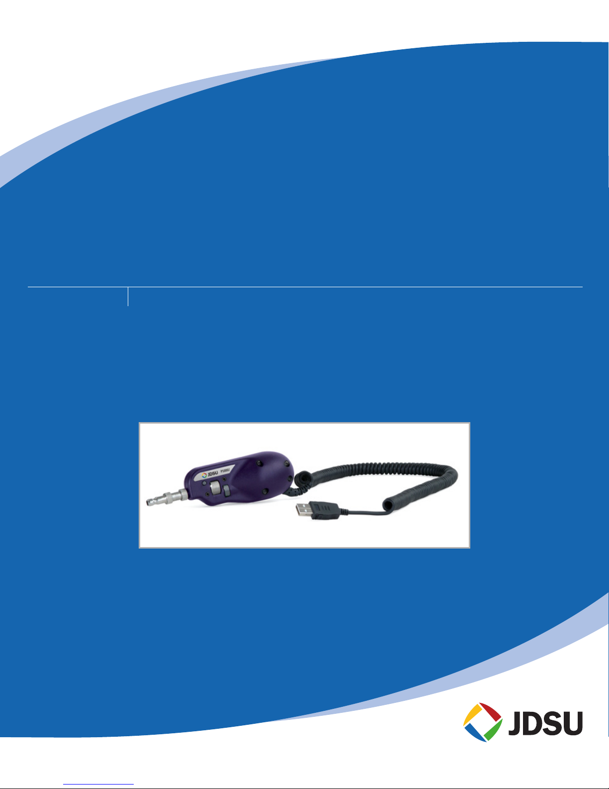
P5000i Digital Analysis Microscope
Automated ber end face inspection and analysis system
USER MANUAL
Page 2

USER MANUAL2
NOTICE Every eort was made to ensure that the information in this document was accurate at the time
of printing. However, information is subject to change without notice, and JDSU reserves the
right to provide an addendum to this document with information not available at the time that
this document was created.
COPYRIGHT © Copyright 2011 JDSU, LLC. All rights reserved. JDSU, Enabling Broadband and Optical
Innovation, and its logo are trademarks of JDSU, LLC. All other trademarks and registered
trademarks are the property of their respective owners. No part of this guide may be reproduced
or transmitted electronically or otherwise without written permission of the publisher.
TRADEMARKS JDSU is a trademark of JDSU in the United States and other countries.
RibbonDrive is a trademark of JDSU.
Hirose is a trademark of Hirose Electric Group.
MTP is a registered trademark of US Conec, Ltd.
Pentium is a registered trademark of Intel Corporation.
Windows is a registered trademark of Microsoft Corporation.
Vista is a registered trademark of Microsoft Corporation.
Excel is a registered trademark of Microsoft Corporation.
Specications, terms, and conditions are subject to change without notice. All trademarks and
registered trademarks are the property of their respective companies.
PATENTS RibbonDrive Tips: US Patent No. 6,751,017 / 6,879,439
CleanBlast: US Patent No. 7,232.262
TESTED EQUIPMENT All pre-qualication tests were performed internally at JDSU, while all nal tests were performed
externally at an independent, accredited laboratory. This external testing guarantees the
unerring objectivity and authoritative compliance of all test results. JDSU's Commerce and
Government Entities (CAGE) code under the North Atlantic Treaty Organization (NATO) is
0L8C3.
FCC INFORMATION Electronic test equipment is exempt from Part 15 compliance (FCC) in the United States.
EUROPEAN UNION Electronic test equipment is subject to the EMC Directive in the European Union. The EN61326
standard prescribes both emission and immunity requirements for laboratory, measurement,
and control equipment. This unit has been tested and found to comply with the limits for a
Class A digital device.
INDEPENDENT
LABORATORY TESTING
This unit has undergone extensive testing according to the European Union Directive and
Standards.
Page 3

P5000i Digital Analysis Microscope 3
Chapter 2
FIBERCHEKPRO™ SOFTWARE / DRIVER INSTALLATION ......................................6–11
Software Install ........................................................................................................................ 6
JDSU (ueye_boot) Driver Install ........................................................................................ 8
JDSU (usbser) Driver Install ................................................................................................. 9
Hardware Install ....................................................................................................................10
TABLE OF CONTENTS
Chapter 4
DEVICE PLATFORMS ........................................................................................................... 20–21
Overview .................................................................................................................................20
Compatible Platforms .........................................................................................................21
Proles ......................................................................................................................................20
Optical Settings ..................................................................................................................... 21
Operating the P5000i on JDSU Test Platforms ...........................................................21
Live View Controls ................................................................................................................ 21
Test View Controls ................................................................................................................21
Device Setup Controls ........................................................................................................21
Chapter 3
FIBERCHEKPRO™ SOFTWARE ........................................................................................ 12–19
Overview .................................................................................................................................12
Controls (LIVE VIEW) ............................................................................................................ 14
Controls (TEST VIEW) ...........................................................................................................15
Using FiberChekPRO with P5000i Digital Analysis Microscope ..........................16
Optical Settings ..................................................................................................................... 18
Proles ......................................................................................................................................19
Chapter 1
P5000i DIGITAL ANALYSIS MICROSCOPE ..................................................................... 4–5
Overview ................................................................................................................................... 4
Controls ...................................................................................................................................... 5
Specications ........................................................................................................................... 5
Page 4
USER MANUAL4
P5000i Digital Analysis Microscope
1
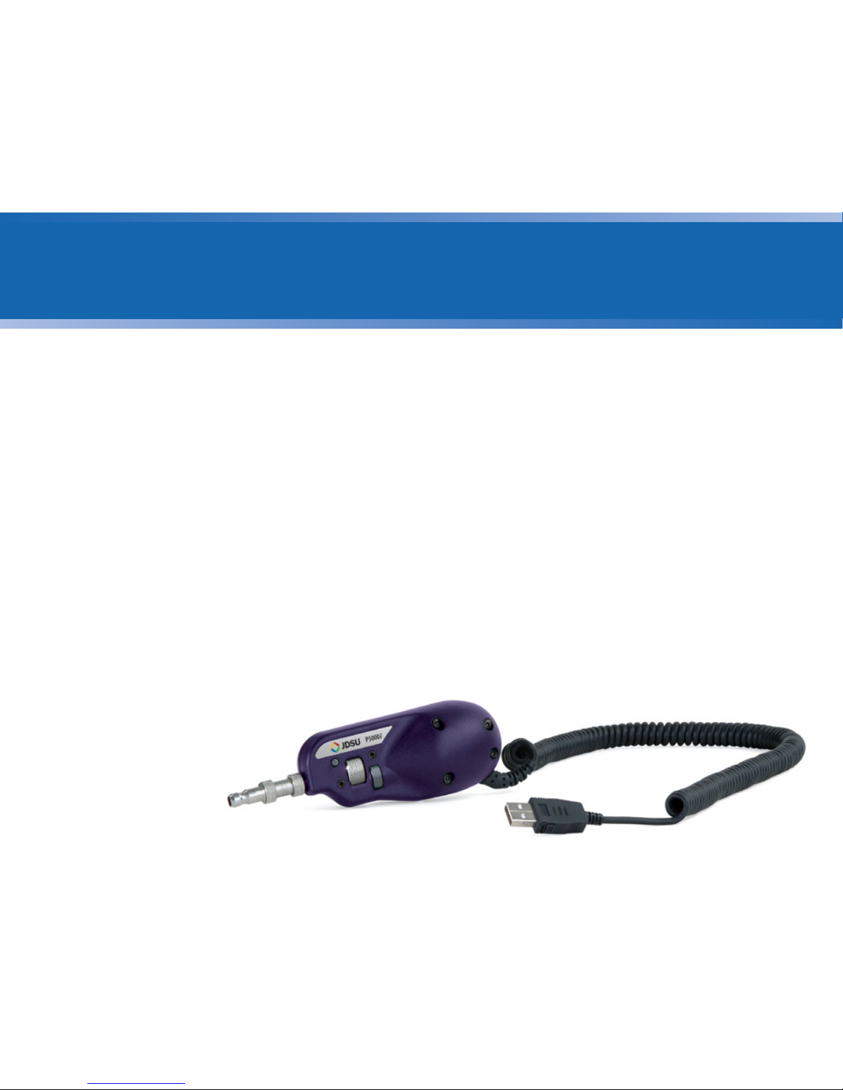
Overview The P5000i Digital Analysis Microscope is a portable handheld microscope used
to inspect and certify both the bulkhead (female) and patch cord (male) sides of
ber connectors as well as other optical devices, such as transceivers. The probe
is specially designed to t and operate comfortably and easily in-hand, allowing
the user to inspect hard-to-reach connectors that are installed on the back side
of patch panels or inside hardware devices. The P5000i automatically inspects and
analyzes the ber end faces, detects scratches and defects, and provides instant
Pass/Fail results. This eliminates subjectivity and time-consuming guesswork from
the inspection process.
The P5000i can deliver these results to a PC/Laptop and JDSU test platforms, such
as the MTS/T-BERD 2000/4000/6000 and HST-3000.
CHAPTER 1 P5000i Digital Analysis Microscope
Page 5
P5000i Digital Analysis Microscope 5
P5000i Digital Analysis Microscope CHAPTER 1
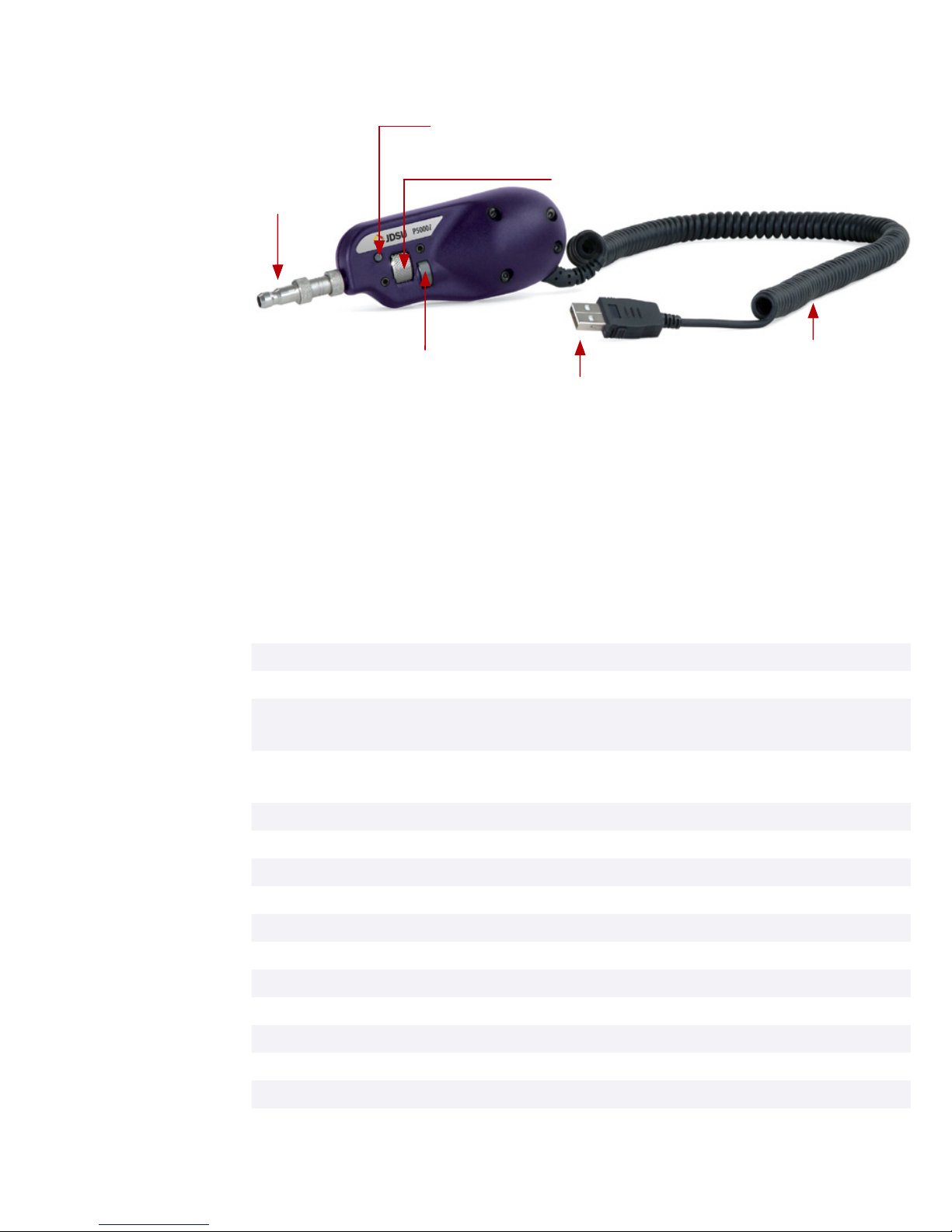
Dimensions 140 x 46 x 44 mm (5.5 x 1.8 x 1.7 in)
Weight 110 g (3.9 oz)
LOW-Mag field-of-view
(FOV)
Horizontal: 740 μm
Vertical: 550 μm
HIGH-Mag FOV Horizontal: 370 μm
Vertical: 275 μm
Live image 640 x 480; 8 fps
Connector USB 2.0
Cord length 183 cm ( 6-ft)
Focus control Adjustable, in-probe
Camera sensor 2560 x 1920, 1/2.5-in (1.02 cm) CMOS
Resolution < 1 μm
Light source Blue LED, 100,000+ hour life
Lighting technique Coaxial
Power source USB port
Certification CE
Warranty 1 year
Specications
Controls
Instantly captures and analyzes the ber image.QuickCapture Button
Allows the user to switch between LOW and HIGH magnications of the ber end
face image.
Magnication Control
Allows the user to adjust focus manually of the live ber end face image on the
display.
Focus Control
FOCUS CONTROL
MAGNIFICATION CONTROL
6 FT COIL CABLE
QUICKCAPTURE™ BUTTON instantly captures and analyzes fiber image
INSPECTION TIP
USB 2.0 CONNECTOR
Page 6
USER MANUAL6
FiberChekPRO Software / Driver Installation
Software Installation
(for use with a
PC/laptop)
2
IMPORTANT! Install the software before attaching the microscope to PC.
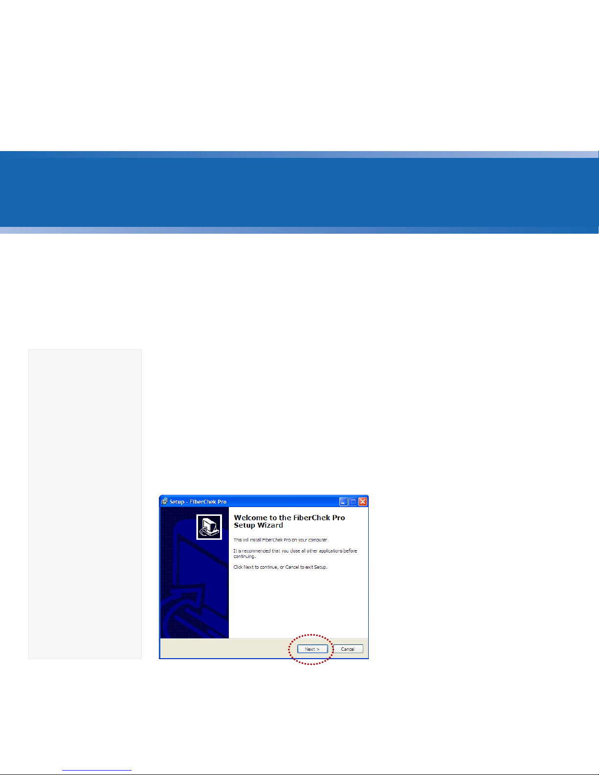
1. Insert FiberChekPRO™ CD
• Insert FiberChekPRO CD and wait for the automatic Welcome to the
FiberChekPRO Setup Wizard menu to launch OR locate the setup file
on the software CD and open.
2. Install FiberChekPRO Software
Minimum
System
Requirements
• PC/laptop with
Pentium® III
1.0 GHz CPU or
higher
• Windows® 2000
(SP4), XP® or
Vista® Operating
System
• 50 MB of hard
drive space
for application
software
• One open USB
2.0 port
• 128 MB RAM
• At the Welcome to the
FiberChekPRO Setup Wizard
menu click Next > to continue.
CHAPTER 2 P5000i Digital Analysis Microscope
Page 7
P5000i Digital Analysis Microscope 7
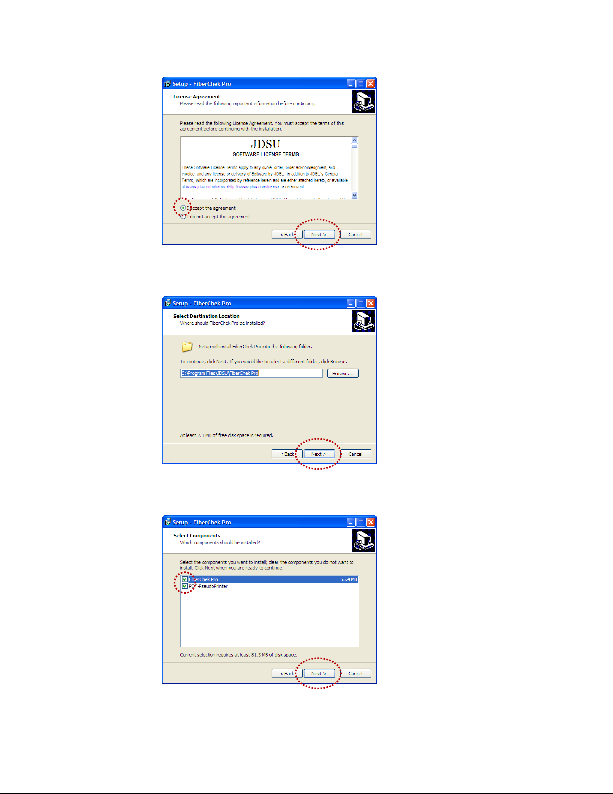
• At the License Agreement menu
select I accept the agreement
button, then click Next > to
continue.
• At the Select Destination Location
menu, accept the default location
(strongly recommended) for the
application files OR click Browse to
select a user-defined location then
click Next > to continue.
FiberChekPRO Software / Driver Installation CHAPTER 2
• At the Select Components menu,
check all the components you
want to install, and make sure the
box next to PDF-PseudoPrinter
is checked and click Next > to
continue.
Page 8
USER MANUAL8
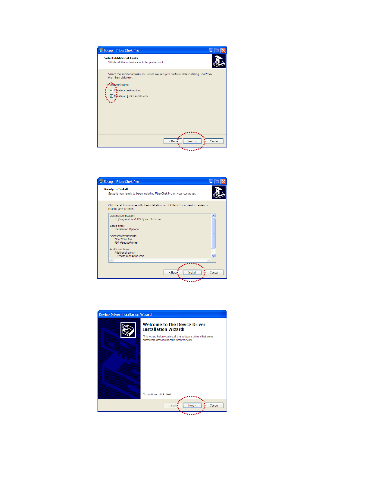
• At the Ready to Install menu,
confirm settings then click Install
to continue.
CHAPTER 2 P5000i Digital Analysis Microscope
JDSU Inc (ueye_boot)
Driver Installation
• At the Welcome to the Device
Driver Installation Wizard menu,
click Next > to continue.
• At the Select Additional Tasks
menu, select/check options for
FiberChekPRO icon/shortcut
placement then click Next > to
continue.
Page 9

P5000i Digital Analysis Microscope 9
JDSU (usbser)
Driver Installation
• At the Completing the Device
Driver Installation Wizard menu,
click Finish to complete JDSU Inc
(ueye_boot) driver installation.
FiberChekPRO Software / Driver Installation CHAPTER 2
• At the Welcome to the Found New
Hardware Wizard menu, click
Next > to continue.
• At the Completing the Device
Driver Installation Wizard menu,
click Finish to complete
JDS Uniphase (usbser) Ports
driver installation.
Page 10

USER MANUAL10
3. Hardware Installation
• Plug the probe microscope into
the computer.
• Wait for the automatic Found
New Hardware Wizard menu to
launch.
Hardware
Installation
CHAPTER 2 P5000i Digital Analysis Microscope
• At the Information menu, click
Next > to continue.
• At the Completing the
FiberChekPRO Setup Wizard, click
Finish to complete software and
driver installation.
Page 11

P5000i Digital Analysis Microscope 11
This page intentionally left blank.
FiberChekPRO Software / Driver Installation CHAPTER 2
Page 12

USER MANUAL12
FiberChekPRO Software
3
Overview The P5000i Digital Analysis Microscope uses FiberChekPRO (automated
analysis software) to operate on a PC/Laptop, and instantly captures, analyzes and
grades ber endface images to obtain a PASS/FAIL result and generate certication
reports.
FiberChekPRO is a software application used to determine the acceptability
of optical ber end faces through automated inspection and analysis. Used in
conjunction with JDSU’s P5000i Digital Analysis Microscope, FiberChekPRO will
identify and characterize defects and contamination then provide a PASS or
FAIL result according to a pre-congured failure criteria setting. In addition, the
program allows users to archive data, generate reports and obtain an Optical Power
Measurement (OPM) with both the MP-series and FI-series test tools from JDSU.
CHAPTER 3 P5000i Digital Analysis Microscope
Page 13

P5000i Digital Analysis Microscope 13
FiberChekPRO™
FiberChekPRO Performs the Following Automated Procedures
1. Acquires the ber image.
2. Analyzes the image.
3. Finds defects and their location to ber core.
4. Measures and evaluates the defects within each specied Zone.
5. Determines whether defects within the Zones are acceptable according to the
pre-congured failure criteria for each Zone.
6. Displays the results as PASS or FAIL.
7. Saves or prints all relative results in designated directory or printer, respectively.
FiberChekPRO Software CHAPTER 3
Page 14

USER MANUAL14
Allows the user to select the specic microscope they want to have active for
displaying on the screen. If multiple microscopes are connected, each one will
appear in a drop down list.
Controls (LIVE VIEW)
MICROSCOPE
CHAPTER 3 P5000i Digital Analysis Microscope
TIP Allows the user to select the best optical settings for the type of inspection tip that
is attached to their probe. Users can select from several pre-congured optical
settings or create their own. For more information, see the OPTICAL SETTINGS section
on page 18.
PROFILE Allows the user to select from various PROFILES, which contain the analysis
parameters by which PASS/FAIL criteria are determined. Users can select from
several pre-congured PROFILES or create their own. For more information, see the
PROFILES section on page 19.
IMAGE CONTROLS Provide specic controls for ne tuning the image. In LIVE view, users can select
between viewing at LOW or HIGH magnication.
FOCUS QUALITY
METER
A visual gauge that aids the users in nding the optimal focus point. Optimal focus
level is reached when the blue bar is closest to the red line.
TEST Initiates the automated PASS/FAIL test process.
SAVE Allows the user to capture and save the image as it appears on the screen.
MICROSCOPE
TEST
SAVE
TIP PROFILE IMAGE CONTROLS
Page 15

P5000i Digital Analysis Microscope 15
Provides specic controls for ne tuning the image. In TEST view, users can:
• SelectbetweenviewingatLOWorHIGHmagnication
• TurntheoverlaydetailsONorOFF
• TurntheScratchViewfeatureONorOFF
Controls (TEST VIEW)
IMAGE CONTROLS
LIVE Allows the user to return back to a live image.
SAVE REPORT Generates a summary report of the tested ber on the screen.
DETAILS Allows the user to view more specic information on the analysis results for the
tested ber on the screen.
MICROSCOPE
LIVE
SAVE REPORT
DETAILS
IMAGE CONTROLS
FiberChekPRO Software CHAPTER 3
Page 16

USER MANUAL16
• Select the appropriate inspection
tip that corresponds to the
connector type and side being
inspected and attach to probe.
INSPECTION TIP BARREL ASSEMBLY
• In the TIP section, select the pre-
configured Optical Setting from
the dropdown list (see page 18
for descriptions).
1. Open/Launch FiberChekPRO
2. Install Inspection Tip
• Locate FiberChekPRO application
and open.
Using FiberChekPRO
with P5000i Digital
Analysis Microscope
CHAPTER 3 P5000i Digital Analysis Microscope
FiberChekPRO
Desktop Icon
3. Select Prole Setting
• From the pre-configured PROFILE
settings dropdown list, select
the appropriate connector being
inspected.
Page 17

P5000i Digital Analysis Microscope 17
5. Focus the Fiber End Face Image On Screen
• Adjust the focus of the fiber end
face image on the computer
screen by turning the Focus
Control on the microscope.
6. Test
• Press the QuickCapture button
on the probe OR click the TEST
button from the FiberChekPRO
toolbar to run analysis.
FiberChekPRO Software CHAPTER 3
4. Inspect Fiber
• Insert the probe into the bulkhead
(for probe) or insert the path cord
ferrule into the probe tip.
Page 18

USER MANUAL18
Optical Settings
• StandardTips(withBAP1)
Select when using standard tips with FBPP-BAP1 barrel assembly. Tips that use this
setting include FBPT-SC, FBPT-LC, FBPT-ST, FBPT-FC, FBPT-SC-APC & FBPT-FC-APC.
• StandardTips(withBAP2)
Select when using standard tips with the FBPP-BAP2 barrel assembly for longer
reach inspection. Note: The FBPP-BAP2 accepts the same tips as the FBPP-BAP1.
• Mil/AeroTips&Guides(withBAP3)
Select when using guides designated for inspecting Military & Aerospace
connectors with the narrow barrel assembly (FBPP-BAP3).
• LongReach(-L)Tips
Select when using long reach inspection tips. Note: Long Reach inspection tips are
noted with the sux “-L” on the part number (ex: FBPT-SC-L, FBPT-LC-L, etc.).
• RibbonTips
Select when using tips designated for inspecting ribbon connectors. Note: Ribbon
connectors contain an array of multiple bers in a single connector (ex: FBPT-MTP).
• E2000Tips
Select when using long reach E2000 inspection tips (ex: FBPT-E2000).
• SC-A6Tip(60DegreeAngle)
Select when using SC inspection tips with a 60 degree angle. Note: Angled
inspection tips are typically noted with the sux “-A6” on the part number (ex: FBPTSC-A6, FBPT-SCA-A6).
NOTE: Users can also create new Optical Settings for specialty tips or applications. See the
FiberChekPRO user manual for details.
Optical Settings congure the P5000i for optimal performance with a given
tip. Users can select the best optical settings for the type of inspection tip that
is attached to their probe. The P5000i comes pre-congured with the following
optical settings:
CHAPTER 3 P5000i Digital Analysis Microscope
Page 19

P5000i Digital Analysis Microscope 19
Proles Contains the analysis parameters by which PASS/FAIL criteria are determined. Users
can activate which proles they want to appear in the PROFILE drop down list on
the main menu by selecting Setup > Analysis Proles.
Proles listed in the ACTIVE section will appear in the drop down menu. Users can
select from several pre-congured PROFILES or create their own.
NOTE: Double-click on an active prole to nd out more information about it.
FiberChekPRO Software CHAPTER 3
Page 20

USER MANUAL20
Device Platforms
4
Overview
Proles
The P5000i Digital Analysis Microscope also operates on several other JDSU
handheld test platforms to instantly capture, analyze and grade ber endface
images to obtain a PASS/FAIL result and generate certication reports. P5000i will
operate on these platforms in a similar way to FiberChekPRO. The user will always
specify what prole to test against and what tip is attached (found in setup or options
menu). For more information on using the P5000i with other device platforms, see
the user manuals for the specic tool or platform.
CHAPTER 4 P5000i Digital Analysis Microscope
Compatible
Platforms
Other platforms that P5000i connects to include but are not limited to:
• MTS/T-BERD2000
• MTS/T-BERD4000
• MTS/T-BERD6000
• T-BERD5800
• HST-3000
• MAP-200
JDSU platforms capable of using the P5000i will come pre-loaded with proles
matching the requirements in IEC-61300-3-35. Users can create new proles using
FiberChekPRO and export them to the JDSU test platform as follows:
1. Create the new prole in FiberChekPRO and close the application.
2. Use Windows Explorer and Browse to the FiberChekPRO install folder (the
default location is C: Program Files/JDSU/FiberChekPro).
Page 21

P5000i Digital Analysis Microscope 21
Device Platforms CHAPTER 4
3. Select the folder named "Proles - Shortcut" (this opens up a folder with all of
your proles in FiberChekPRO).
4. Copy the Proles you want to add onto the test platform and save to a
portable USB memory stick.
5. Connect the USB memory stick to the test platform and save the prole le(s)
to the location specied in the platform manual.
Optical Settings congure the P5000i for optimal performance with a given
tip. Users can select the best optical settings for the type of inspection tip that
is attached to their probe. The P5000i comes pre-congured with a selection of
default optical settings (see page 18). Additional settings can be added to the
P5000i using FiberChekPRO. See the FiberChekPRO user manual for further details
on this process.
Optical Settings
Operating the
P5000i on JDSU
Test Platforms
While each JDSU test platform will have its own user interface, all platforms will
have common controls for inspection and analysis.
Live View Controls Focus Quality: A visual gauge that aids the users in nding the optimal focus
point. Optimal focus level is reached when the blue bar is closest to the red line.
Test: Initiates the automated PASS/FAIL test process.
Magnication Selection: Select between viewing at LOW or HIGH magnication.
Test View Controls Live: Allows the user to return back to a live image.
Overlays: Toggles an overlay of the zones and analysis details ON or OFF.
Magnication Selection: Select between viewing at LOW or HIGH magnication
inspected image.
Save Report: Generates a summary report of the tested ber on the screen.
Device Setup
Controls
Tip: Allows the user to select the best optical settings for the type of inspection
tip that is attached to their probe. Users can select from several pre-congured
optical settings or create their own. For more information, see the OPTICAL SETTINGS
section on page 18.
Prole: Allows the user to select from various PROFILES, which contain the
analysis parameters by which PASS/FAIL criteria are determined. Users can select
from several pre-congured PROFILES or create their own. For more information
about PROFILES, see the PROFILES section on page 19.
Page 22

USER MANUAL22
Customer Support
JDSU Communication Test and Measurement Headquarters
One Milestone Center Court
Germantown, MD 20876-7100
Toll Free: 1 866 228-3762
Tel: + 1 301 353-1550
Fax: + 1 301 353-1536
Web: www.jdsu.com/inspect
Technical Assistance for JDSU Fiber Inspection, Cleaning and Test
Tel: 1 800 304-3202
Hours: M–F 7:00 AM to 5:30 PM (Pacic Standard Time)
E-mail: FIT.Service@jdsu.com
Customer Care for JDSU Fiber Inspection, Cleaning and Test
Tel: 1 800 304-3202
E-mail: Ger.NewOrders@jdsu.com
P5000i Digital Analysis Microscope
Page 23

P5000i Digital Analysis Microscope 23
This page left intentionally blank.
Page 24

NORTH AMERICA
TEL: 1 866 228 3762
FAX: 1 301 353 9216
LATIN AMERICA
TEL: +1 954 688 5660
FAX: +1 954 345 4668
ASIA PACIFIC
TEL: +852 2892 0990
FAX: +852 2892 0770
EMEA
TEL: +49 7121 86 2222
FAX: +49 7181 86 1222
www.jdsu.com/inspect
Test and Measurement Regional Sales
ZPPKG0574
REV 0
Product specications and descriptions in this document subject to change without notice. © 2011 JDS Uniphase Corporation. June 2011
 Loading...