

Page 1

1 GSM/GPRS/EDGE SIGNAL ANALYZER
JD7105B Base St at ion Analyzer
GSM/GPRS/EDGE Signal Analyzer
This GSM/GPRS/EDGE Signal Analyzer function is optional that the JD7105B Base Station Analyzer
offers as the Option 022 for GSM/GPRS/EDGE. It allows the user to check conformity to the 3GPP TS
51.021 Base Station System (BSS) equipment specification: Radio Aspects V8.9.0 (2003-06) and
analyze GSM/EDGE system performance. The GSM//GPRS/EDGE OTA Analyzer which is the Option
042 can be added to the GSM/GPRS/EDGE Signal Analyzer for Over The Air measurement.
In this Chapter
Using GSM/GPRS/EDGE Signal Analyzer .............................................................................................. 4
Display Overview
Connecting a Cable
Direct Connection
Indirect Connection
Over The Air (OTA)
Spectrum Analysis Measurement
Setting Mode
Setting Frequency
Setting Amplitude
Setting Averaging
Setting Sweep Mode
Setting Trace and Display
Measurement Example
Using Marker
Using Peak Search
RF Analysis Measurements
Setting Mode
Setting Frequency
Setting Amplitude
Setting Averaging
Setting Sweep Mode
Setting Trigger Source
Channel Power ...................................................................................................................................... 21
Measurement Procedure
Setting Limit
Measurement Example
Using Marker
Using Peak Search
Occupied Bandwidth
Measurement Procedure
Setting Limit
..................................................................................................................................... 5
................................................................................................................................. 7
...................................................................................................................... 7
................................................................................................................... 7
................................................................................................................... 8
............................................................................................................ 9
............................................................................................................................. 9
..................................................................................................................... 9
.................................................................................................................... 10
.................................................................................................................... 12
............................................................................................................... 12
....................................................................................................... 12
........................................................................................................... 13
........................................................................................................................... 13
................................................................................................................. 15
................................................................................................................... 16
........................................................................................................................... 16
................................................................................................................... 16
.................................................................................................................... 17
.................................................................................................................... 19
............................................................................................................... 19
............................................................................................................ 19
........................................................................................................ 21
............................................................................................................................ 22
........................................................................................................... 23
........................................................................................................................... 23
................................................................................................................. 24
.............................................................................................................................. 25
........................................................................................................ 25
............................................................................................................................ 25
Page 2

GSM/GPRS/EDGE SIGNAL ANALYZER 2
JD7105B Base St at ion Analyzer
Measurement Example ........................................................................................................... 27
Using Marker
Using Peak Search
Spectrum Emission Mask (SEM)
Measurement Procedure
Setting Limit
Measurement Example
Using Marker
Using Peak Search
Spurious Emissions
Measurement Procedure
Setting Limit
Measurement Example
Using Marker
Using Peak Search
Power vs Time Measurements
Setting Mode
Setting Frequency
Setting Amplitude
Setting Averaging
Setting Sweep Mode
Setting Trigger Source
Setting External Clock
Measurement Procedure
Setting Limit
Measurement Example
Constellation Measurement
Setting Mode
Setting Frequency
Setting Amplitude
Setting Averaging
Setting Trace and Display
Setting Sweep Mode
Setting Trigger Source
Setting External Clock
Measurement Procedure
Setting Limit
Measurement Example
GSM OTA Measurements
Setting Mode
Setting Frequency for Channel/Frequency Scanners
Setting Amplitude
Setting Sweep Mode
Setting Trigger Source
Setting External Clock
GSM OTA Channel Scanner
Setting Mode
Setting Channel
Setting Zoom Position
Measurement Procedure
Measurement Example
GSM OTA Frequency Scanner
Setting Mode
........................................................................................................................... 27
................................................................................................................. 28
........................................................................................................... 29
........................................................................................................ 29
............................................................................................................................ 30
........................................................................................................... 31
........................................................................................................................... 31
................................................................................................................. 32
............................................................................................................................... 33
........................................................................................................ 33
............................................................................................................................ 35
........................................................................................................... 36
........................................................................................................................... 36
................................................................................................................. 37
.............................................................................................................. 38
........................................................................................................................... 38
................................................................................................................... 38
.................................................................................................................... 39
.................................................................................................................... 41
............................................................................................................... 41
............................................................................................................ 41
............................................................................................................. 42
........................................................................................................ 43
............................................................................................................................ 44
........................................................................................................... 46
................................................................................................................... 47
........................................................................................................................... 47
................................................................................................................... 47
.................................................................................................................... 48
.................................................................................................................... 49
....................................................................................................... 50
............................................................................................................... 50
............................................................................................................ 50
............................................................................................................. 51
........................................................................................................ 52
............................................................................................................................ 53
........................................................................................................... 56
...................................................................................................................... 57
........................................................................................................................... 57
............................................................. 57
.................................................................................................................... 59
............................................................................................................... 60
............................................................................................................ 60
............................................................................................................. 60
.................................................................................................................. 62
........................................................................................................................... 62
....................................................................................................................... 62
............................................................................................................. 63
........................................................................................................ 63
........................................................................................................... 64
.............................................................................................................. 65
........................................................................................................................... 65
Page 3

3 GSM/GPRS/EDGE SIGNAL ANALYZER
JD7105B Base St at ion Analyzer
Setting Frequency ................................................................................................................... 65
Setting Zoom Position
Measurement Procedure
Measurement Example
GSM OTA Multipath Profile
Setting Mode
Measurement Procedure
Measurement Example
GSM OTA Modulation Analyzer
Setting Mode
Measurement Procedure
Setting Limit
Measurement Example
............................................................................................................. 66
........................................................................................................ 66
........................................................................................................... 67
.................................................................................................................... 68
........................................................................................................................... 68
........................................................................................................ 68
........................................................................................................... 69
............................................................................................................. 71
........................................................................................................................... 71
........................................................................................................ 71
............................................................................................................................ 72
........................................................................................................... 75
(Rev. 3.0)
Page 4

GSM/GPRS/EDGE SIGNAL ANALYZER 4
JD7105B Base St at ion Analyzer
USING GSM/GPRS/EDGE SIGNAL ANALYZER
The Global System for Mobile Communications (GSM) is a digital cellular standard that uses Time
Division Multiple Access (TDMA) multiplexing scheme and Gaussian Minimum Shift Keying (GMSK)
modulation. The Enhanced Data Rates for GSM Evolution (EDGE) is an enhancement to GSM that
promises to deliver true 3G wireless services such as multimedia and other broadband applications. It
uses TDMA and 3π/8 8PSK (phase shift keying) modulation.
The JD7105B performs measurements using the methods and limits as defined in the 3GPP TS
51.021 Base Station System (BSS) equipment specification: Radio Aspects V8.9.0 (2003-06). The
Pass/Fail indictor helps the user to determine base station performance easily.
The JD7105B provides the following analysis tools for GSM/GPRS/EDGE system.
Spectrum Analysis
RF Analysis
Channel Power
Occupied Bandwidth
Spectrum Emission Mask
Spurious Emissions
Power vs Time
Slot
Frame
Constellation
Over The Air (OTA)
Channel Scanner
Frequency Scanner
Multipath Profile
Modulation Analyzer
Auto Measure
Page 5
5 GSM/GPRS/EDGE SIGNAL ANALYZER
JD7105B Base St at ion Analyzer
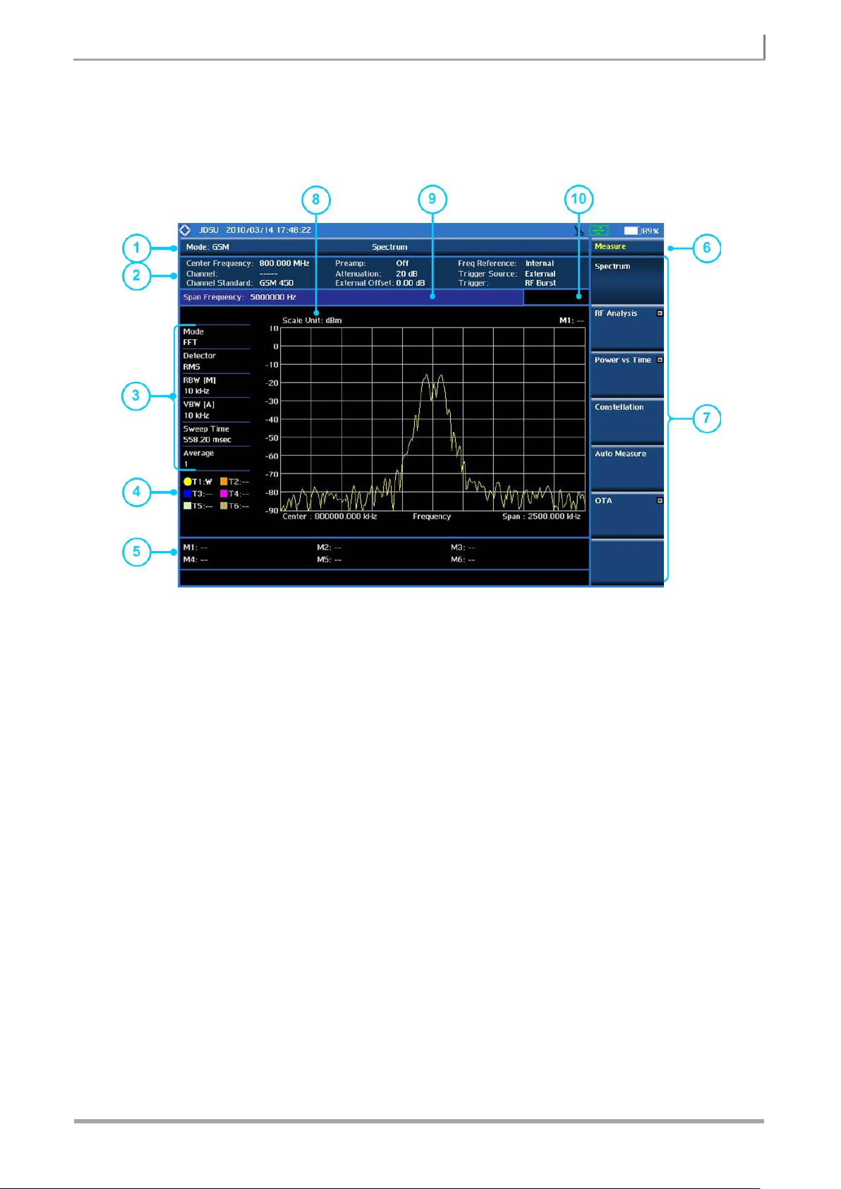
DISPLAY OVERVIEW
Overview of GSM Signal Analyzer Display
① Measurement Mode Information: GSM Signal Analyzer
② Spectrum Windows X and Y Scale or Setting Information: This window shows the most
common settings or parameters of each measurement. Frequency/Channel setting, Amplitude
setting (Preamp, Attenuat ion, Ex tern al offset), Ref eren ce setting infor m ation Freq uency/Trigger)
③ Measurement Setting Information
- Spectrum Analyzer Operation Mode Information: Displays the operation mode of
spectrum analyzer, Sweep or FFT
- Detector Type Setting Information: Displays the current selected detector types, Normal,
Peak, RMS, Negative Peak, and Sample
- Spectrum Window’s X Scale Setting Information: Displays RBW, VBW settings
[A]: Auto mode, [M]: Manual mode
- Sweep Time Information: Displays current sweep time
- Average Number Information set through BW/AVG hard key. It shows the number of
traces to be averaged.
Page 6

GSM/GPRS/EDGE SIGNAL ANALYZER 6
JD7105B Base St at ion Analyzer
④ Trace Information
C: Captured
M: Max Hold
m: Min Hold
W: Write Current Trace (Indicates current active trace)
L: Loaded
F: Trace View Off
⑤ Information on Marker Table displays up to 6 markers
⑥ Screen Menu Title
⑦ Screen Menu and Sub-menu
⑧ Scale Unit Information: dBm, dBmV, dBuV, V, and W
⑨ User Input Window: Activates when user input menu or key is selected. Pressing PREV hard
key will cancel or deactivate user input window. Inactivate user input window before usin g 7-hot
keys.
NOTE: It is very important to inactivate the user input window when you intend to use the hot
key menu on the numeric keys.
⑩ Pass/Fail Indicator
Page 7
7 GSM/GPRS/EDGE SIGNAL ANALYZER
JD7105B Base St at ion Analyzer
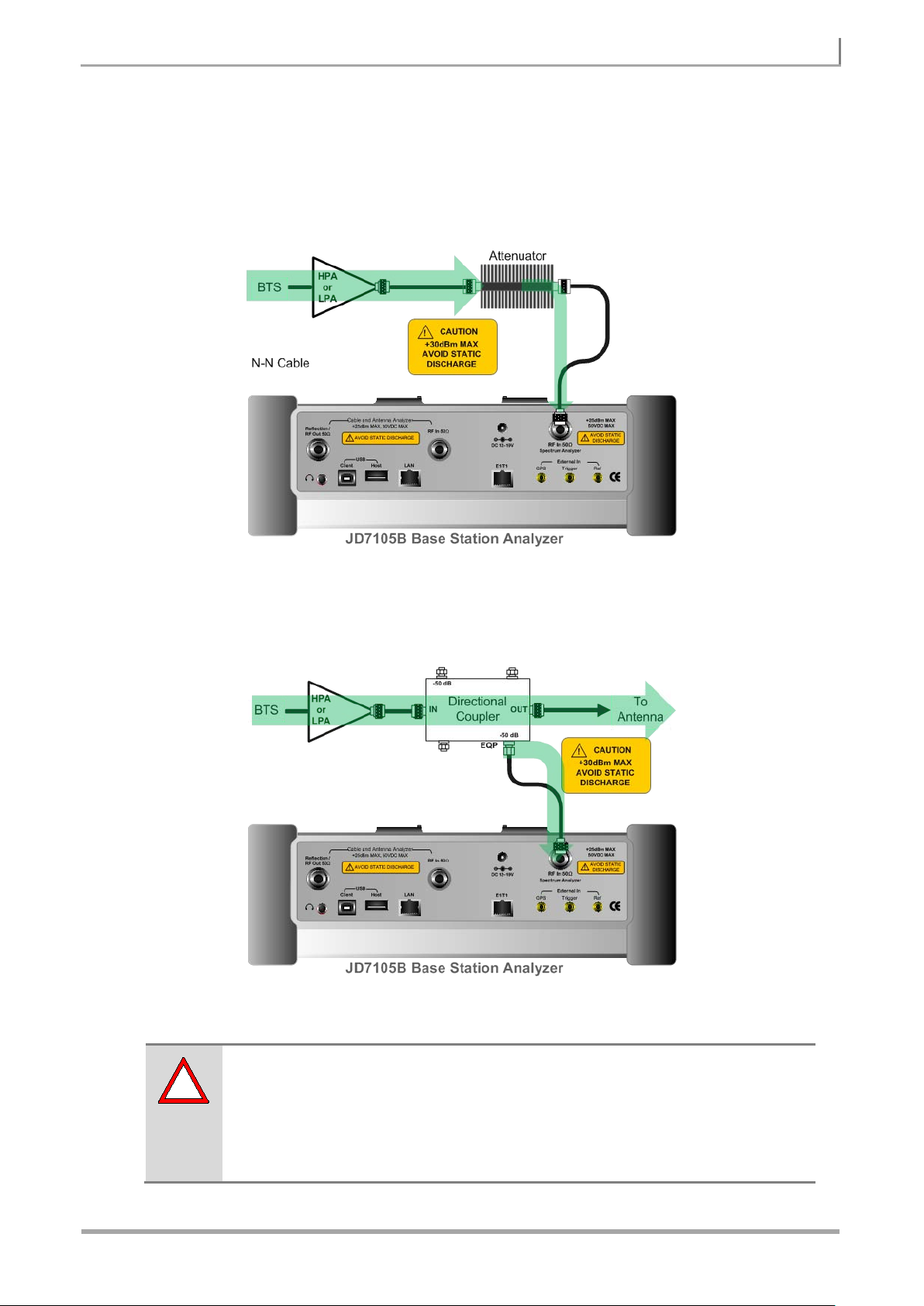
!
Direct Connection
CONNECTING A CABLE
PA Output Port and RF In Port Connection
Indirect Connection
Monitor Port and RF In Port Connection
The maximum power for the Spectrum Analyzer RF In 50Ω port is 30 dBm (1
Watt). If the input signal level to be measured is greater than 30 dBm, use a High
Power Attenuator to prevent damage when you directly connect the signal to the
instrument. Or connect a signal from the coupling port of a directional coupler.
Page 8
GSM/GPRS/EDGE SIGNAL ANALYZER 8
JD7105B Base St at ion Analyzer
!
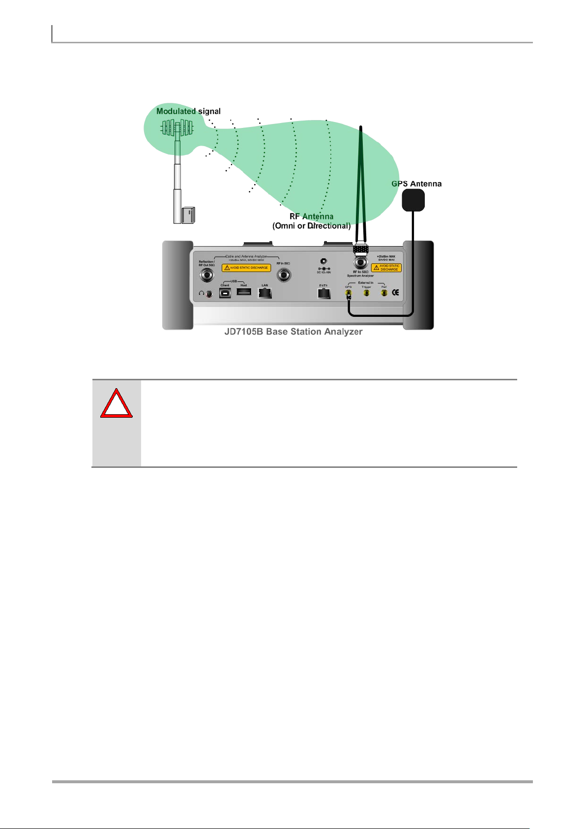
Over The Air (OTA)
The maximum power for the Spectrum Analyzer RF In 50Ω port is 30 dBm (1
Watt). If the input signal level to be measured is greater than 30 dBm, use a High
Power Attenuator to prevent damage when you directly connect the signal to the
instrument. Or connect a signal from the coupling port of a directional coupler.
OTA Connection
Page 9

9 GSM/GPRS/EDGE SIGNAL ANALYZER
JD7105B Base St at ion Analyzer
1. Connect the cable
Connect the signal to the Spectrum A naly zer RF In 50Ω
2. Select the mode
1. Set the frequency
2. Select the channel standard
SPECTRUM ANALYSIS MEASUREMENT
Setting Mode
Step Description
port using the cable whose loss was measured.
MODE
[Signal Analyzer]
[GSM]
[Spectrum]
Setting Frequency
Step Description
FREQ/DIST
[Center Frequency]
Enter a value
[GHz], [MHz], [kHz], or [Hz]
or
[Channel Number]
Enter a value
[Forward] or [Reverse]
Press the MODE hard key.
Press the Signal Analyzer soft key.
Press the GSM soft key.
Press the Spectrum soft key. (Spectrum mode is set by
default.)
Press the FREQ/DIST hard key.
Press the Center Frequency soft key.
Use the numeric keys, the rotary knob, or the arrow keys.
When using the numeric keys, the input is completed by
selecting one of the unit soft keys.
Press the Channel Number soft key.
Enter a channel number using the numeric keys.
Select the direction by pressing the Forward or Reverse.
[Channel Standard]
Select a channel standard
[Select] or ENTER
Press the Channel Standard soft key to get the pop-up
window of the channel standard list.
Press the arrow keys, rotate the knob, or press the Page Up
and Page Down soft keys to highlight a frequency band to
select.
Press the Select soft key or the ENTER hard key.
Page 10
GSM/GPRS/EDGE SIGNAL ANALYZER 10
JD7105B Base St at ion Analyzer
1. Set the reference level
2. Set the attenuation level
FREQ/DIST
CENTER FREQUENCY: Changes the center frequency setup. Values can be entered with the
numeric keys, the rotary knob, or the arrow keys. When using the numeric keys, the input is
completed by selecting one of the unit soft keys including GHz, MHz, kHz, and Hz. When using
the rotary knob or the arrow keys, the frequency changes in a predefined frequency step. The
frequency step can be configured by selecting the Frequency Step soft key.
CHANNEL NUMBER: Enters a channel number and selects the Forward or Reverse soft key.
When using the rotary knob or the arrow keys, the channel changes in a predefined channel step.
The channel step can be configured by selecting the Channel Step soft key.
FREQUENCY STEP: Defines the moving step size of the Center Frequency when using the
rotary knob or the arrow keys. The step size can be en ter ed b y using numeric keys and the unit
soft keys.
CHANNEL STEP: Defines the moving step size of the Channel Number when using the rotary
knob or the arrow keys. The step size can be entered by using numeric keys and the Enter soft
key.
CHANNEL STANDARD: When the channel standard is selected from the list, the center
frequency information on the display screen wi ll be mapped accordingly to the selected channel
standard. The channel standards available in the instrument are listed in the Appendix C – Band,
Frequency & Channel Standard.
Setting Amplitude
Step Description
AMP/SCALE
[Reference Level]
Enter a reference level value
[dBm] or ENTER
Press the AMP/SCALE hard key.
Press the Reference Level soft key.
Use the numeric keys or the rotary knob that changes in a 10
dB step.
Press the dBm soft key or the ENTER hard key.
[Attenuation]
<Auto> or <Manual>
Enter an attenuation value
Press the Attenuation soft key. The Auto mode is set by
default. This key toggles between the Auto and Manual.
Press the Attenuation soft key to highlight the Manual mode
and change the attenuation value to optimize S/N.
Use the numeric keys or the rotary knob that changes in a 5
dB step. The attenuation settin g range is 0 to 55 dB.
Page 11
11 GSM/GPRS/EDGE SIGNAL ANALYZER
JD7105B Base St at ion Analyzer
!
If the input signal level is higher than +30 dBm or higher than the allowable mixer
AMP/SCALE
AUTO SCALE: The instrument can automatically set the scale to the minimum and maximum
values on the Y-axis of the graph for optimum display of the traces measured. Each time the Auto
Scale is selected, the top and bottom scales are set to the minimum and maximum values with
margin on the Y-axis of the display screen.
REFERENCE LEVEL: Sets the maximum Y-axis range when using the Spectrum Analyzer or
Signal Analyzer function.
SCALE/DIV: Is used only for the Spectrum measurement screen. It represents the value of one
division on the horizontal scale. The default value is 10 dB per divis ion and the Y-Scale is set to
100 dB. Selecting the Scale/Div soft key enables to set the value to 1 dB per division with the
numeric keys or the rotary knob.
ATTENUATION
AUTO: Input attenuator’s value is automatically set depending on the reference level. This is
the default operation mode, so it is recommended to use this mode unless a special
measurement condition is needed.
MANUAL: Sets the attenuator’s value for the Spectrum Analyzer RF In 50Ω port. The
reference level changes according to the change of the attenuator’s value, but the
attenuator’s value does not change when the reference level is changed.
input limit per input attenuator’s value set by the user, a “IF Overload” message will
be displayed on the screen indicating that the input attenuation value must be
increased. When the instrument is exposed to an over power condition for a long
time, its performance may be degraded.
PREAMP: Turns on or off the internal pre-amplifier. The pre-amplifier is to amplify a low-level
input signal. This soft key toggles between the On and Off. When it is turned on, the allowable
attenuation input range is 0 dB to 10 dB w ith 5 dB step. If user sets attenuation value beyond 10
dB, then the instrument will automatically turn off pre-amplifier to display low level signal properly
on the screen.
UNITS: Sets the scale unit on the display among dBm, dBmV, dBuV, V, and W.
EXTERNAL OFFSET: Sets an external offset value. An offset consists of a cable loss and a user
offset and the measurement result shows the value reflecting both offset values. When the
external offset value is set at 40 dB in the Spectrum mode, the measurement result compensates
40 dB at both the Spectrum Analyzer and Signal Analyzer modes.
Page 12

GSM/GPRS/EDGE SIGNAL ANALYZER 12
JD7105B Base St at ion Analyzer
1. Set the sweep mode
1. Set the averaging
2.
3. [Enter] or ENTER
Press the Enter soft key or the ENTER hard key.
Setting Averaging
BW/AVG
AVERAGE: Sets the number of measurements to be averaged for the trace presentation. A
maximum of 99 times of averaging can be set.
Step Description
BW/AVG
[Average]
Enter number of averaging to set Use the numeric keys and input a number between 1 and 99.
Press the BW/AVG hard key.
Press the Average soft key.
When the averaging reaches to the number set here, a new
measurement value replaces the earliest measurement value
in sequence.
Setting Sweep Mode
SWEEP
This hot key is used to set the sweep parameters. The user input window must be inactive first to get
the Sweep hot key function other than the number input.
SWEEP MODE: Sets the sweep method. Toggle between Continue and Single.
Step Description
Setting Trace and Display
TRACE/DISPLAY
SELECT TRACE: Selects an active trace from T1 to T6. Trace numbers are assigned to each
captured trace or loaded trace. Pressing one of the 6 trace number soft keys sets the selected
trace number as the active trace on the display screen.
SWEEP
[Sweep Mode]
Press the SWEEP hot key. It is the number 1 key in the
numeric keypad.
Press the Sweep Mode soft key. Toggle between
Continue and Single.
Page 13
13 GSM/GPRS/EDGE SIGNAL ANALYZER
JD7105B Base St at ion Analyzer
CLEAR WRITE: Clears the selected trace and writes or assigns the current trace.
M AX HOLD: Sets the active trace to display the maximum response of the input signal. Active
trace compares newly acquired data with the trace shown on the screen and displays the bigger
trace on the display screen.
MIN HOLD: Sets the active trace to displa y the minimum response of the input signal. Active trace
compares newly acquired data with the trace shown on the screen and displays the smaller trace
on the display screen.
CAPTURE: Captures a current trace on the display screen with the selected trace number.
TRACE VIEW: Displays the trace of the selected trace number on the display screen or hides it
from the display screen. Press the Select Trace soft key to select a trace number and then press
the Trace View sof t key to toggle between the Off to hide and On to restore a hidden trace.
TRACE CLEAR ALL: Deletes all traces from the instrument and initializes the trace settings.
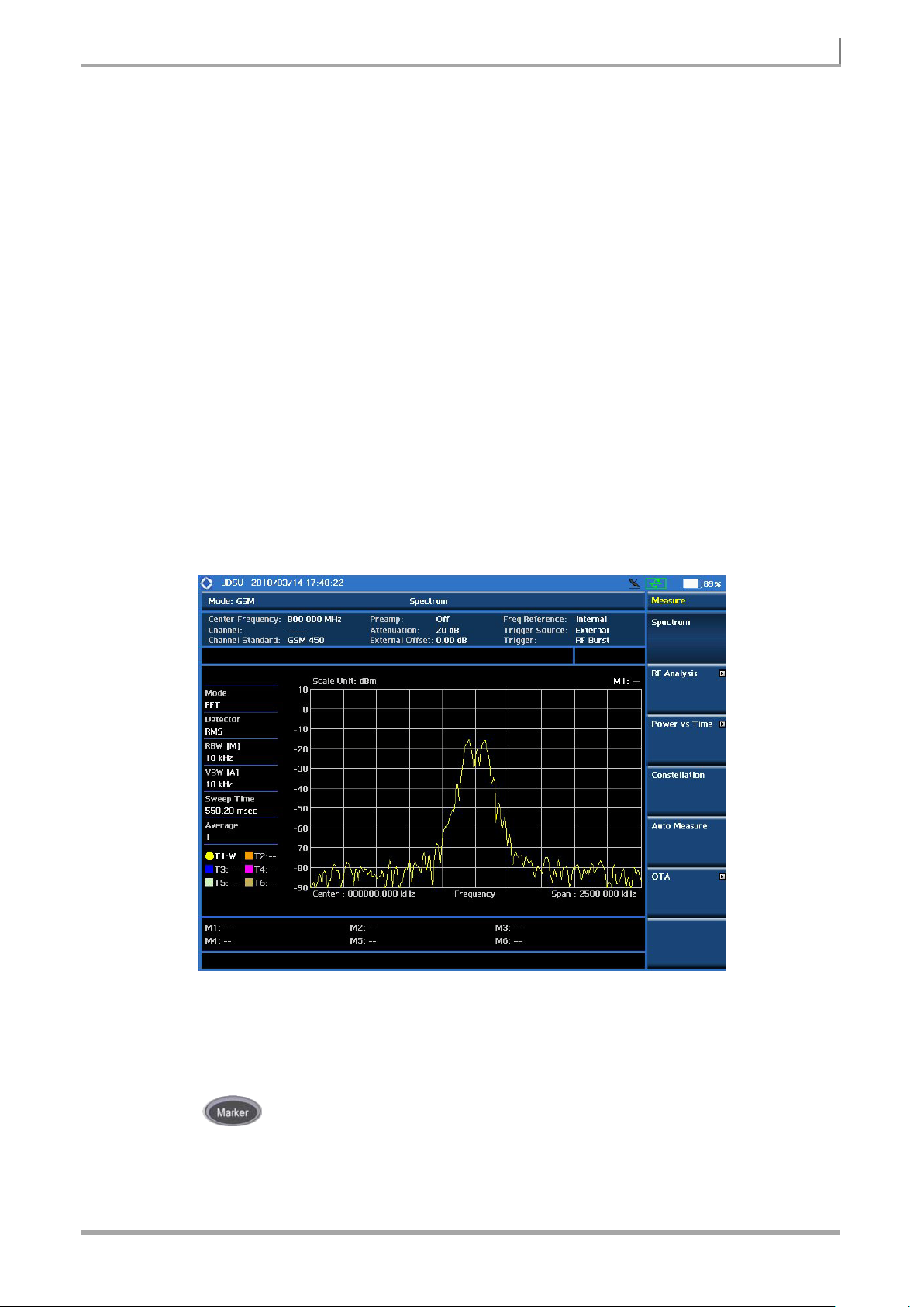
Measurement Example
GSM Spectrum Analysis Measurement Screen
Using Marker
MARKER
Marker is used to get the information about a specific trace. Six markers can be set on the display and
each marker can be used independently. The X and Y coordinates of the trace are displayed when the
Page 14

GSM/GPRS/EDGE SIGNAL ANALYZER 14
JD7105B Base St at ion Analyzer
marker is placed on any position of the tr ace. The position dis p laying the marker’s X and Y
coordinates may be slightly different for each measurement mode and refer to the description of each
measurement. There are three different marker types available: Normal, Delta, and Delta pair. Marker
position can be set manually by entering numeric values (frequency) when one of the marker types is
selected.
SELECT MARKER: Selects an active marker whose position can be changed with the rotary
knob or the arrow keys. The assigned number of the active marker is displayed in the Select
Marker menu box and the active marker number is also displayed right next to the active marker
on the trace when the Marker View is set to On.
MARKER VIEW: Displays the selected marker on the screen or hides it. When the Marker View
is turned off and then on ag ain in the same measurement mode, markers appear at the previous
positions. If a m eas urem ent mode is changed, markers are not restored to t he ir p r evious posi tio ns .
NORMAL: This Normal marker type provides the reading of a marker position on the trace along
with the marker number between 1 and 6.
DELTA: This Delta marker type is associated with a Normal marker. A Normal marker must be set
before a Delta marker is set. When the Delta marker is set, the position set by the Delta marker
becomes the reference position of the Normal marker and the marker’s X and Y values displays
the difference compared with the Delta marker.
DELTA PAIR: This Delta Pair marker type is associated with a Normal marker. A Normal marker
must be set before a Delta Pair marker is set. When the Delta Pair marker is set, the position set
by the Delta Pair marker becomes the reference position of the Normal marker and the marker’s X
and Y values displays the difference compared with the Delta Pair marker. The reference position
will be varied in accordance with trace change.
MARKER ALL OFF: Turns all the markers the screen off. When the Marker View is selected for
those markers, the instrument displays those markers back at the previous position. If a
measurement mode is changed, current settings are not restored.
MARKER: Sets the X coordinate of the active marker as selected.
MARKERCENTER: Sets the frequency of the active marker to the center frequency of
spectrum analyzer.
MARKERSTART: Sets the frequency of the active marker to the start frequency of
spectrum analyzer.
MARKERSTOP: Sets the frequency of the active marker to the stop frequency of spectrum
analyzer.
Page 15

15 GSM/GPRS/EDGE SIGNAL ANALYZER
JD7105B Base St at ion Analyzer
Using Peak Search
PEAK SEARCH
Each time the Peak Search soft key is pressed, the active marker is positioned at the highest peak of
the trace.
PEAK SEARCH: Moves the active marker to the highest peak of the trace.
NEXT PEAK: Moves the active marker to the second highest peak of the trace.
NEXT PEAK RIGHT: Moves the active marker to the highest peak to the right of its current
position.
NEXT PEAK LEFT: Moves the active marker to the highest peak to the left of its current position.
MIN SEARCH: Moves the active marker to the lowest peak of the trace.
ALWAYS PEAK : When the Always Peak is set to On, the instrument moves the active marker
automatically to the highest peak of the trace every time the trace is refreshed.
Page 16
GSM/GPRS/EDGE SIGNAL ANALYZER 16
JD7105B Base St at ion Analyzer
Connect the signal to the Spectrum A naly zer RF In 50Ω
2. Select the mode
1. Set the frequency
2. Select the channel standard
RF ANALYSIS MEASUREMENTS
GSM/GPRS/EDGE Signal Analysis provides the following measurements for RF Analysis.
Channel Power
Occupied Bandwidth
Spectrum Emission Mask
Spurious Emissions
Setting Mode
Step Description
1. Connect the cable
port using the cable whose loss was measured.
MODE
[Signal Analyzer]
[GSM]
[RF Analysis]
Setting Frequency
Step Description
FREQ/DIST
[Center Frequency]
Enter a value
[GHz], [MHz], [kHz], or [Hz]
or
[Channel Number]
Enter a value
[Forward] or [Reverse]
Press the MODE hard key.
Press the Signal Analyzer soft key.
Press the GSM soft key.
Press the RF Analysis soft key.
Press the FREQ/DIST hard key.
Press the Center Frequency soft key.
Use the numeric keys, the rotary knob, or the arrow keys.
When using the numeric keys, the input is completed by
selecting one of the unit soft keys.
Press the Channel Number soft key.
Enter a channel number using the numeric keys.
Select the direction by pressing the Forward or Reverse.
[Channel Standard]
Select a channel standard
[Select] or ENTER
Press the Channel Standard soft key to get the pop-up
window of the channel standard list.
Press the arrow keys, rotate the knob, or press the Page Up
and Page Down soft keys to highlight a frequency band to
select.
Press the Select soft key or the ENTER hard key.
Page 17

17 GSM/GPRS/EDGE SIGNAL ANALYZER
JD7105B Base St at ion Analyzer
1. Set the reference level
2. Set the attenuation level
FREQ/DIST
This setting is not used in the Spurious Emissions mode.
CENTER FREQUENCY: Changes the center frequency setup. Values can be entered with the
numeric keys, the rotary knob, or the arrow keys. When using the numeric keys, the input is
completed by selecting one of the unit soft keys including GHz, MHz, kHz, and Hz. When using
the rotary knob or the arrow keys, the frequency changes in a predefined frequency step. The
frequency step can be configured by selecting the Frequency Step soft key.
CHANNEL NUMBER: Enters a channel number and selects the Forward or Reverse soft key.
When using the rotary knob or the arrow keys, the channel changes in a predefined channel step.
The channel step can be configured by selecting the Channel Step soft key.
FREQUENCY STEP: Defines the moving step size of the Center Frequency when using the
rotary knob or the arrow keys. The step size can be en ter ed b y using numeric keys and the unit
soft keys.
CHANNEL STEP: Defines the moving step size of the Channel Number when using the rotary
knob or the arrow keys. The step size can be entered by using numeric keys and the Enter soft
key.
CHANNEL STANDARD: When the channel standard is selected from the list, the center
frequency information on the display screen will be mapped accordingly to the selected channel
standard. The channel standards available in the instrument are listed in the table in the Appendix
C – Band, Frequency & Channel Standard.
Setting Amplitude
Step Description
AMP/SCALE
[Reference Level]
Enter a reference level value
[dBm] or ENTER
Press the AMP/SCALE hard key.
Press the Reference Level soft key.
Use the numeric keys or the rotary knob that changes in a 10
dB step.
Press the dBm soft key or the ENTER hard key.
[Attenuation]
<Auto> or <Manual>
Enter an attenuation value
Press the Attenuation soft key. The Auto mode is set by
default. This key toggles between the Auto and Manual.
Press the Attenuation soft key to highlight the Manual mode
and change the attenuation value to optimize S/N.
Use the numeric keys or the rotary knob that changes in a 5
dB step. The attenuation settin g range is 0 to 55 dB.
Page 18

GSM/GPRS/EDGE SIGNAL ANALYZER 18
JD7105B Base St at ion Analyzer
!
If the input signal level is higher than +30 dBm or higher than the allowable mixer
AMP/SCALE
AUTO SCALE: The instrument can automatically set the scale to the minimum and maximum
values on the Y-axis of the graph for optimum display of the traces measured. Each time the Auto
Scale is selected, the top and bottom scales are set to the minimum and maximum values with
margin on the Y-axis of the display screen.
REFERENCE LEVEL: Sets the maximum Y-axis range when using the Spectrum Analyzer or
Signal Analyzer function.
SCALE/DIV: Is used only for the Spectrum measurement screen. It represents the value of one
division on the horizontal scale. The default value is 10 dB per divis ion and the Y-Scale is set to
100 dB. Selecting the Scale/Div soft key enables to set the value to 1 dB per division with the
numeric keys or the rotary knob.
ATTENUATION
AUTO: Input attenuator’s value is automatically set depending on the reference level. This is
the default operation mode, so it is recommended to use this mode unless a special
measurement condition is needed.
MANUAL: Sets the attenuator’s value for the Spectrum Analyzer RF In 50Ω port. The
reference level changes according to the change of the attenuator’s value, but the
attenuator’s value does not change when the reference level is changed.
input limit per input attenuator’s value set by the user, a “IF Overload” message will
be displayed on the screen indicating that the input attenuation value must be
increased. When the instrument is exposed to an over power condition for a long
time, its performance may be degraded.
PREAMP: Turns on or off the internal pre-amplifier. The pre-amplifier is to amplify a low-level
input signal. This soft key toggles between the On and Off. When it is turned on, the allowable
attenuation input range is 0 dB to 10 dB w ith 5 dB step. If user sets attenuation value beyond 10
dB, then the instrument will automatically turn off pre-amplifier to display low level signal properly
on the screen.
UNITS: Sets the scale unit on the display among dBm, dBmV, dBuV, V, and W.
EXTERNAL OFFSET: Sets an external offset value. An offset consists of a cable loss and a user
offset and the measurement result shows the value reflecting both offset values. When the
external offset value is set at 40 dB in the Spectrum mode, the measurement result compensates
40 dB at both the Spectrum Analyzer and Signal Analyzer modes.
Page 19

19 GSM/GPRS/EDGE SIGNAL ANALYZER
JD7105B Base St at ion Analyzer
1. Set the averaging
2.
3. [Enter] or ENTER
Press the Enter soft key or the ENTER hard key.
Setting Averaging
BW/AVG
AVERAGE: Sets the number of measurements to be averaged for the trace presentation. A
maximum of 99 times of averaging can be set.
Step Description
BW/AVG
[Average]
Enter number of averaging to set Use the numeric keys and input a number between 1 and 99.
Press the BW/AVG hard key.
Press the Average soft key.
When the averaging reaches to the number set here, a new
measurement value replaces the earliest measurement value
in sequence.
Setting Sweep Mode
SWEEP
This hot key is used to set the sweep parameters. The user input window must be inactive first to get
the Sweep hot key function other than the number input.
SWEEP MODE: Sets the sweep method. Toggle between Continue and Single.
Setting Trigger Source
TRIGGER
This hot key is used to select the trigger source among RF Burst, Internal FB, RF Burst & TS,
External, and Free. It is the same number 4 key in the numeric keypad functioning when the value
input bar on the screen is inactive.
Step Description
1. Set the sweep mode
SWEEP
[Sweep Mode]
Press the SWEEP hot key. It is the number 1 key in the
numeric keypad.
Press the Sweep Mode soft key. Toggle between
Continue and Single.
Page 20

GSM/GPRS/EDGE SIGNAL ANALYZER 20
JD7105B Base St at ion Analyzer
RF BURST: Sets the trigger level when using the RF Burst (wideband) trigger. The value is
relative to the peak of the signal. RF Burst is also known as RF Envelope.
INTERNAL FB (FREE BURST): Sets the trigger level to FB if there is a frequency burst signal.
RF BURST & TS (TRAINING SEQUENCE): Sets the trigger level to Training Sequence Code.
EXTERNAL: Sets the trigger level to external trigger reference.
FREE: Sets the free trigger (auto trigger).
Page 21
21 GSM/GPRS/EDGE SIGNAL ANALYZER
JD7105B Base St at ion Analyzer
1. Connect the cable
Connect the cable to the S pectrum A naly zer RF In 50Ω
3. Set the measurement parameters
CHANNEL POWER
The Channel Power measures in-channel power for GSM/GPRS and EDGE systems. GSM/GPRS
and EDGE systems use dynamic power control to ensure that each link is maintained with minimum
power. It gives two fundamental benefits of keeping overall system interference to a minimum level
and of maximizing battery life in the case of mobile stations. The Channel Power measurement
determines the average power of an RF signal burst at or above a specified threshold value. The
threshold value may be absolute or relative to the peak value of the signal.
The purpose of the Channel Power measurement is to determine the power delivered to the antenna
system on the RF channel under test. The instrument acquires a GSM/GPRS or EDGE signal in the
time domain. The average power level above the threshold is then computed and displayed.
Measurement Procedure
Step Description
2. Set the measurement mode
MODE
[Signal Analyzer]
[GSM]
[RF Analysis]
[Channel Power]
MEASURE SETUP
[Delay]
Enter a value
[uSec] or ENTER
[RX Filter]
[No Filter], [100K], [200K],
[400K (Default)], or [624K]
GSM Channel Power Measurement Procedure
port of the JD7105B and the RF Output port of BTS.
Press the MODE hard key.
Press the soft key to select the Signal Analyzer mode.
Press the GSM soft key.
Press the RF Analysis soft key.
Press the Channel Power soft key.
Press the MEASURE SETUP hard key.
Press the Delay soft key to set the delay.
Use the numeric keys to input value.
Press the unit soft key or the ENTER hard key.
Press the RX Filter soft key to select the internal RX filter
bandwidth among the choices.
MEASURE SETUP
DELAY: Sets the delay in micro seconds. Use the numeric keys to input value and press the unit
soft key to complete the input.
Page 22
GSM/GPRS/EDGE SIGNAL ANALYZER 22
JD7105B Base St at ion Analyzer
1. Select the limit mode
2. Set the limit
RX FILTER: Sets the internal RX filter bandwidth among 100K, 200K, 400K, and 624K. Default
setting is 400K.
Setting Limit
LIMIT
This hot key is used to set the threshold value for the limit line on the display screen. It turns on or off
the limit or band limit settings of the measurement for pass/fail indication. The user input window must
be inactive first to get the Limit hot key function other than the number input.
Step Description
LIMIT
[RF Test Limits]
[Channel Power]
[Test Limits]
<On> or <Off>
[High Limit]
Enter a value
[dBm] or ENTER
[Low Limit]
Enter a value
[dBm] or ENTER
3. Enable beep
LIMIT
[Beep]
<On> or <Off>
Press the LIMIT hot key. It is the number 7 key in the
numeric keypad.
Press the RF Test Limits soft key to enable or disable
test limits on RF Analysis measurements.
Press the Channel Power soft key.
Press the Test Limits soft key to toggle between On and
Off and select one.
Press the High Limit soft key to set the upper limit of the
Pass/Fail criteria. Use the numeric keys to input value.
Press the unit soft key or the ENTER hard key.
Press the Low Limit soft key to set the lower limit of the
Pass/Fail criteria. Use the numeric keys to input value.
Press the unit soft key or the ENTER hard key.
Press the LIMIT hot key. It is the number 7 key in the
numeric keypad.
Press the Beep soft key to toggle between On and Off
and select one. This will make audible alar m if the
measurement beyond the limit.
TEST LIMITS: Enables or disables Pass/Fail results on the display screen. Toggle the Test
Limits soft key to select it to On or Off.
HIGH LIMIT : Sets the upper limit of the Pass/Fail criteria. Use the numeric keys to enter a
threshold or limit value and press the dBm unit soft key or the ENTER hard key to complete the
input.
LOW LIMIT: Sets the lower limit of the Pass/Fail criteria. Use the numeric keys to enter a
Page 23
23 GSM/GPRS/EDGE SIGNAL ANALYZER
JD7105B Base St at ion Analyzer
threshold or limit value and press the dBm unit soft key or the ENTER hard key to complete the
input.
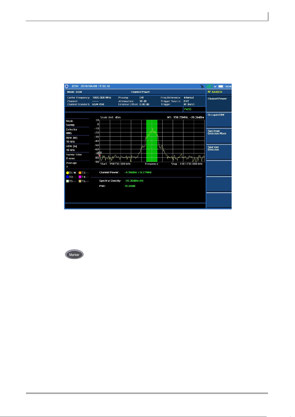
Measurement Example
GSM Channel Power Measurement Screen
Using Marker
MARKER
Marker is used to get the information about a specific trace. Six markers can be set on the display and
each marker can be used independently. The X and Y coordinates of the trace are displayed when the
marker is placed on any position of the trace. The position displaying the marker’s X and Y
coordinates may be slightly different for each measurement mode and refer to the description of each
measurement. There are three different marker types available: Normal, Delta, and Delta pair. Marker
position can be set manually by entering numeric values (frequency) when one of the marker types is
selected.
SELECT MARKER: Selects an active marker whose position can be changed with the rotary
knob or the arrow keys. The assigned number of the active marker is displayed in the Select
Marker menu box and the active marker number is also displayed right next to the active marker
on the trace when the Marker View is set to On.
MARKER VIEW: Displays the selected marker on the screen or hides it. When the Marker View
Page 24

GSM/GPRS/EDGE SIGNAL ANALYZER 24
JD7105B Base St at ion Analyzer
is turned off and then on ag ain in the same measurement mode, markers appear at the previous
positions. If a m eas urem ent mode is changed, markers are not restored to t he ir p r evious posi tio ns .
NORMAL: This Normal marker type provides the reading of a marker position on the trace along
with the marker number between 1 and 6.
DELTA: This Delta marker type is associated with a Normal marker. A Normal marker must be set
before a Delta marker is set. When the Delta marker is set, the position set by the Delta marker
becomes the reference position of the Normal marker and the marker’s X and Y values displays
the difference compared with the Delta marker.
DELTA PAIR: This Delta Pair marker type is associated with a Normal marker. A Normal marker
must be set before a Delta Pair marker is set. When the Delta Pair marker is set, the position set
by the Delta Pair marker becomes the reference position of the Normal marker and the marker’s X
and Y values displays the difference compared with the Delta Pair marker. The reference position
will be varied in accordance with trace change.
MARKER ALL OFF: Turns all the markers the screen off. When the Marker View is selected for
those markers, the instrument displays those markers back at the previous position. If a
measurement mode is changed, current settings are not restored.
Using Peak Search
PEAK SEARCH
Each time the Peak Search soft key is pressed, the active marker is positioned at the highest peak of
the trace.
PEAK SEARCH: Moves the active marker to the highest peak of the trace.
NEXT PEAK: Moves the active marker to the second highest peak of the trace.
NEXT PEAK RIGHT: Moves the active marker to the highest peak to the right of its current
position.
NEXT PEAK LEFT: Moves the active marker to the highest peak to the left of its current position.
MIN SEARCH: Moves the active marker to the lowest peak of the trace.
ALWAYS PEAK : When the Always Peak is set to On, the instrument moves the active marker
automatically to the highest peak of the trace every time the trace is refreshed.
Page 25

25 GSM/GPRS/EDGE SIGNAL ANALYZER
JD7105B Base St at ion Analyzer
Connect the cable to the S pectrum A naly zer RF In 50Ω
2. Set the measurement mode
3. Set the measurement parameters
OCCUPIED BANDWIDTH
It determines the frequency bandwidth that contains 99% of the total radiated power.
Measurement Procedure
Step Description
1. Connect the cable
port of the JD7105B and the RF Output port of BTS.
MODE
[Signal Analyzer]
[GSM]
[RF Analysis]
[Occupied BW]
MEASURE SETUP
[Delay]
Enter a value
[uSec] or ENTER
[RX Filter]
[No Filter], [100K], [200K],
[400K (Default)], or [624K]
GSM Occupied BW Measurement Procedure
Press the MODE hard key.
Press the soft key to select the Signal Analyzer mode.
Press the GSM soft key.
Press the RF Analysis soft key.
Press the Occupied BW soft key.
Press the MEASURE SETUP hard key.
Press the Delay soft key to set the delay.
Use the numeric keys to input value.
Press the unit soft key or the ENTER hard key.
Press the RX Filter soft key to select the internal RX filter
bandwidth among the choices.
MEASURE SETUP
DELAY: Sets the delay in micro seconds. Use the numeric keys to input value and press the unit
soft key to complete the input.
RX FILTER: Sets the internal RX filter bandwidth among 100K, 200K, 400K, and 624K. Default
setting is 400K.
Setting Limit
LIMIT
This hot key is used to set the threshold value for the limit line on the display screen. It turns on or off
the limit or band limit settings of the measurement for pass/fail indication. The user input window must
Page 26

GSM/GPRS/EDGE SIGNAL ANALYZER 26
JD7105B Base St at ion Analyzer
1. Select the limit mode
2. Set the limit
3. Enable beep
be inactive first to get the Limit hot key function other than the number input.
Step Description
LIMIT
[RF Test Limits]
[Occupied BW]
[Test Limits]
<On> or <Off>
[High Limit]
Enter a value
[MHz], [kHz], or [Hz]
LIMIT
[Beep]
<On> or <Off>
Press the LIMIT hot key. It is the number 7 key in the
numeric keypad.
Press the RF Test Limits soft key.
Press the Occupied BW soft key.
Press the Test Limits soft key to toggle between On and
Off and select one.
Press the High Limit soft key to set the upper limit of the
Pass/Fail criteria. Use the numeric keys to input value.
Press the unit soft key to select.
Press the LIMIT hot key. It is the number 7 key in the
numeric keypad.
Press the Beep soft key to toggle between On and Off
and select one. This will make audible alar m if the
measurement beyond the limit.
TEST LIMITS: Enables or disables Pass/Fail results on the display screen. Toggle the Test
Limits soft key to select it to On or Off.
HIGH LIMIT : Sets the upper limit of the Pass/Fail criteria. Use the numeric keys to enter a
threshold or limit value and press one of the unit soft keys to complete the input.
Page 27

27 GSM/GPRS/EDGE SIGNAL ANALYZER
JD7105B Base St at ion Analyzer
Measurement Example
GSM Occupied Bandwidth Measurement Screen
Using Marker
MARKER
Marker is used to get the information about a specific trace. Six markers can be set on the display and
each marker can be used independently. The X and Y coordinates of the trace are displayed when the
marker is placed on any position of the trace. The position displaying the marker’s X and Y
coordinates may be slightly different for each measurement mode and refer to the description of each
measurement. There are three different marker types available: Normal, Delta, and Delta pair. Marker
position can be set manually by entering numeric values (frequency) when one of the marker types is
selected.
SELECT MARKER: Selects an active marker whose position can be changed with the rotary
knob or the arrow keys. The assigned number of the active marker is displayed in the Select
Marker menu box and the active marker number is also displayed right next to the active marker
on the trace when the Marker View is set to On.
MARKER VIEW: Displays the selected marker on the screen or hides it. When the Marker View
is turned off and then on ag ain in the same measurement mode, markers appear at the previous
positions. If a m eas urem ent mode is changed, markers are not restored to t he ir p r evious posi tio ns .
NORMAL: This Normal marker type provides the reading of a marker position on the trace along
with the marker number between 1 and 6.
Page 28

GSM/GPRS/EDGE SIGNAL ANALYZER 28
JD7105B Base St at ion Analyzer
DELTA: This Delta marker type is associated with a Normal marker. A Normal marker must be set
before a Delta marker is set. When the Delta marker is set, the position set by the Delta marker
becomes the reference position of the Normal marker and the marker’s X and Y values displays
the difference compared with the Delta marker.
DELTA PAIR: This Delta Pair marker type is associated with a Normal marker. A Normal marker
must be set before a Delta Pair marker is set. When the Delta Pair marker is set, the position set
by the Delta Pair marker becomes the reference position of the Normal marker and the marker’s X
and Y values displays the difference compared with the Delta Pair marker. The reference position
will be varied in accordance with trace change.
MARKER ALL OFF: Turns all the markers the screen off. When the Marker View is selected for
those markers, the instrument displays those markers back at the previous position. If a
measurement mode is changed, current settings are not restored.
MARKER: Sets the X coordinate of the active marker as selected.
MARKERCENTER: Sets the center frequency of the spectrum to the active marker.
MARKERSTART: Sets the start frequency of the spectrum to the active marker.
MARKERSTOP: Sets the stop frequency of the spectrum to the active marker.
Using Peak Search
PEAK SEARCH
Each time the Peak Search soft key is pressed, the active marker is positioned at the highest peak of
the trace.
PEAK SEARCH: Moves the active marker to the highest peak of the trace.
NEXT PEAK: Moves the active marker to the second highest peak of the trace.
NEXT PEAK RIGHT: Moves the active marker to the highest peak to the right of its current
position.
NEXT PEAK LEFT: Moves the active marker to the highest peak to the left of its current position.
MIN SEARCH: Moves the active marker to the lowest peak of the trace.
ALWAYS PEAK : When the Always Peak is set to On, the instrument moves the active marker
automatically to the highest peak of the trace every time the trace is refreshed.
Page 29

29 GSM/GPRS/EDGE SIGNAL ANALYZER
JD7105B Base St at ion Analyzer
1. Connect the cable
Connect the cable to the S pectrum A naly zer RF In 50Ω
2. Set the measurement mode
SPECTRUM EMISSION MASK (SEM)
The Spectrum Emission Mask (SEM) measurement verifies whether or not the transmitter transmits
undesirable energy into the transmission band. This energy may cause interference with other users of
the GSM system.
Measurement Procedure
Step Description
port of the JD7105B and the RF Output port of BTS.
MODE
[Signal Analyzer]
[GSM]
[RF Analysis]
[Spectrum Emission Mask]
3. Set the measurement parameters
MEASURE SETUP
[Delay]
Enter a value
[uSec] or ENTER
[RX Filter]
[No Filter], [100K], [200K],
[400K (Default)], or [624K]
GSM Spectrum Emission Mask Measurement Procedure
Press the MODE hard key.
Press the soft key to select the Signal Analyzer mode.
Press the GSM soft key.
Press the RF Analysis soft key.
Press the Spectrum Emission Mask soft key.
Press the MEASURE SETUP hard key.
Press the Delay soft key to set the delay.
Use the numeric keys to input value.
Press the unit soft key or the ENTER hard key.
Press the RX Filter soft key to select the internal RX filter
bandwidth among the choices.
MEASURE SETUP
DELAY: Sets the delay in micro seconds. Use the numeric keys to input value and press the unit
soft key to complete the input.
RX FILTER: Sets the internal RX filter bandwidth among 100K, 200K, 400K, and 624K. Default
setting is 400K.
Page 30

GSM/GPRS/EDGE SIGNAL ANALYZER 30
JD7105B Base St at ion Analyzer
2. Set the limit
3. Enable beep
Setting Limit
LIMIT
This hot key is used to set the threshold value for the limit line on the display screen. It turns on or off
the limit or band limit settings of the measurement for pass/fail indication. The user input window must
be inactive first to get the Limit hot key function other than the number input.
Step Description
1. Select the limit mode
LIMIT
[RF Test Limits]
[Spectrum Emission Mask]
[Test Limits]
<On> or <Off>
LIMIT
[Beep]
<On> or <Off>
Press the LIMIT hot key. It is the number 7 key in the
numeric keypad.
Press the RF Test Limits soft key.
Press the Spectrum Emission Mask soft key.
Press the Test Limits soft key to toggle between On and
Off and select one.
Press the LIMIT hot key. It is the number 7 key in the
numeric keypad.
Press the Beep soft key to toggle between On and Off
and select one. This will make audible alar m if the
measurement beyond the limit.
TEST LIMITS: Enables or disables Pass/Fail results on the display screen. Toggle the Test
Limits soft key to select it to On or Off.
Page 31

31 GSM/GPRS/EDGE SIGNAL ANALYZER
JD7105B Base St at ion Analyzer
Measurement Example
GSM Spectrum Emission Mask Measurement Screen
Using Marker
MARKER
Marker is used to get the information about a specific trace. Six markers can be set on the display and
each marker can be used independently. The X and Y coordinates of the trace are displayed when the
marker is placed on any position of the trace. The position displaying the marker’s X and Y
coordinates may be slightly different for each measurement mode and refer to the description of each
measurement. There are three different marker types available: Normal, Delta, and Delta pair. Marker
position can be set manually by entering numeric values (frequency) when one of the marker types is
selected.
SELECT MARKER: Selects an active marker whose position can be changed with the rotary
knob or the arrow keys. The assigned number of the active marker is displayed in the Select
Marker menu box and the active marker number is also displayed right next to the active marker
on the trace when the Marker View is set to On.
MARKER VIEW: Displays the selected marker on the screen or hides it. When the Marker View
is turned off and then on ag ain in the same measurement mode, markers appear at the previous
positions. If a m eas urem ent mode is changed, markers are not restored to t he ir p r evious posi tio ns .
NORMAL: This Normal marker type provides the reading of a marker position on the trace along
with the marker number between 1 and 6.
Page 32

GSM/GPRS/EDGE SIGNAL ANALYZER 32
JD7105B Base St at ion Analyzer
DELTA: This Delta marker type is associated with a Normal marker. A Normal marker must be set
before a Delta marker is set. When the Delta marker is set, the position set by the Delta marker
becomes the reference position of the Normal marker and the marker’s X and Y values displays
the difference compared with the Delta marker.
DELTA PAIR: This Delta Pair marker type is associated with a Normal marker. A Normal marker
must be set before a Delta Pair marker is set. When the Delta Pair marker is set, the position set
by the Delta Pair marker becomes the reference position of the Normal marker and the marker’s X
and Y values displays the difference compared with the Delta Pair marker. The reference position
will be varied in accordance with trace change.
MARKER ALL OFF: Turns all the markers the screen off. When the Marker View is selected for
those markers, the instrument displays those markers back at the previous position. If a
measurement mode is changed, current settings are not restored.
Using Peak Search
PEAK SEARCH
Each time the Peak Search soft key is pressed, the active marker is positioned at the highest peak of
the trace.
PEAK SEARCH: Moves the active marker to the highest peak of the trace.
NEXT PEAK: Moves the active marker to the second highest peak of the trace.
NEXT PEAK RIGHT: Moves the active marker to the highest peak to the right of its current
position.
NEXT PEAK LEFT: Moves the active marker to the highest peak to the left of its current position.
MIN SEARCH: Moves the active marker to the lowest peak of the trace.
ALWAYS PEAK : When the Always Peak is set to On, the instrument moves the active marker
automatically to the highest peak of the trace every time the trace is refreshed.
Page 33

33 GSM/GPRS/EDGE SIGNAL ANALYZER
JD7105B Base St at ion Analyzer
Connect the cable to the S pectrum A naly zer RF In 50Ω
2. Set the measurement mode
3. Set the measurement parameters
SPURIOUS EMISSIONS
Out-of-band emissions are unwanted emissions immediately outside the channel bandwidth resulting
from the modulation process and non-linearity in the transmitter but excluding spurious emissions. The
Spurious Emissions measurement is to identify and determine the power level of out-of-band spurious
emission within the necessary channel bandwidth and modulated signal measured at the RF port of
the Base Station.
Measurement Procedure
Step Description
1. Connect the cable
port of the JD7105B and the RF Output port of BTS.
MODE
[Signal Analyzer]
[GSM]
[RF Analysis]
[Spurious Emissions]
MEASURE SETUP
[Range Table]
[Range]
Enter a value
[Enter]
[Start Frequency]
Enter a value
[GHz], [MHz], [kHz], or [Hz]
[Stop Frequency]
Enter a value
[GHz], [MHz], [kHz], or [Hz]
[RBW]
Enter a value
[GHz], [MHz], [kHz], or [Hz]
[VBW]
Enter a value
[GHz], [MHz], [kHz], or [Hz]
[Start Limit]
Enter a value
[dBm]
Press the MODE hard key.
Press the soft key to select the Signal Analyzer mode.
Press the GSM soft key.
Press the RF Analysis soft key.
Press the Spurious Emissions soft key.
Press the MEASURE SETUP hard key.
Press the Range Table soft key.
Press the Range soft key.
Use the numeric keys to select the ra nge num ber.
Press the Enter soft key.
Press the Start Frequency soft key.
Use the numeric keys.
Press one of the unit soft keys to select.
Press the Stop Frequency soft key.
Use the numeric keys.
Press one of the unit soft keys to select.
Press the RBW soft key.
Use the numeric keys.
Press one of the unit soft keys to select.
Press the VBW soft key.
Use the numeric keys.
Press one of the unit soft keys to select.
Press the Start Limit soft key.
Use the numeric keys.
Press the unit soft key to complete the input.
Page 34

GSM/GPRS/EDGE SIGNAL ANALYZER 34
JD7105B Base St at ion Analyzer
[Stop Limit]
Press the Stop Limit soft key.
Enter a value
[dBm]
[Measure Type]
<Examine> or <Full>
GSM Spurious Emissions Measurement Procedure
Use the numeric keys.
Press the unit soft key to complete the input.
Press the Measure Type soft key to toggle between
Examine and Full.
MEASURE SETUP
Sets the measurement parameters including range table and measurement type. The measurement
settings can be saved and recalled as a file. Also, JDViewer, PC application software allows the user
to set the parameters in the user’s computer to import into the instrument.
RANGE TABLE: Sets the range table parameters.
RANGE: Adds a new range number or selects one of the existing range numbers to show or
hide the particular frequency range in the range table at the bottom of the screen. Use the
numeric keys to enter a range number and press the Enter soft key to complete the input.
Each time the Range soft key is press, it toggles between On and Off.
START FREQUENCY: Sets or changes the start frequency value to be measured for the
selected range number in the Range menu. Use the numeric keys to enter a value and press
one of the unit soft keys.
STOP FREQUENCY: Sets or changes the stop frequency value to be measured for the
selected range number in the Range menu. Use the numeric keys to enter a value and press
one of the unit soft keys.
RBW: Sets the resolution bandwidth for the selected range number in the Range menu.
VBW: Sets the video bandwidth for the selected range number in the Range menu.
START LIMIT: Set the start value of the limit line for the displayed range.
STOP LIMIT: Set the stop value of the limit line for the displayed range.
MEASURE TYPE: Sets the measurement type to Examine or Full. T oggle between Examine and
Full. Examine mode will show selected range only. The instrument will automatically switch and
show all ranges when Full is selected.
RANGE: Selects the range number to be displayed on the screen. Use the numeric keys to select
one of the existing range numbers that are configured in the Range Table menu. Pressing the
Enter soft key completes the input and changes the display.
SAVE/RECALL SETTING: Saves the measurement parameter settings as a file or retrieves a
measurement setting file saved in the instrument or generated by JDViewer software application.
Page 35

35 GSM/GPRS/EDGE SIGNAL ANALYZER
JD7105B Base St at ion Analyzer
2. Set the limit
Setting Limit
LIMIT
This hot key is used to set the threshold value for the limit line on the display screen. It turns on or off
the limit or band limit settings of the measurement for pass/fail indication. The user input window must
be inactive first to get the Limit hot key function other than the number input.
Step Description
1. Select the limit mode
LIMIT
[RF Test Limits]
[Spurious Emissions]
[Test Limit]
<On> or <Off>
3. Enable beep
LIMIT
[Beep]
<On> or <Off>
Press the LIMIT hot key. It is the number 7 key in the
numeric keypad.
Press the RF Test Limits soft key to enable or disable
test limits on RF Analysis measurements.
Press the Spurious Emissions soft key.
Press the Test Limit soft key to toggle between On and
Off and select one.
Press the LIMIT hot key. It is the number 7 key in the
numeric keypad.
Press the Beep soft key to toggle between On and Off
and select one. This will make audible alar m if the
measurement result goes beyond the limit.
TEST LIMIT: Enables or disables Pass/Fail results on the display screen. Toggle the Test Limit
soft key to select it to On or Off.
Page 36

GSM/GPRS/EDGE SIGNAL ANALYZER 36
JD7105B Base St at ion Analyzer
Measurement Example
GSM Spurious Emissions Measurement Screen
Using Marker
MARKER
Marker is used to get the information about a specific trace. Six markers can be set on the display and
each marker can be used independently. The X and Y coordinates of the trace are displayed when the
marker is placed on any position of the trace. The position displaying the marker’s X and Y
coordinates may be slightly different for each measurement mode and refer to the description of each
measurement. There are three different marker types available: Normal, Delta, and Delta pair. Marker
position can be set manually by entering numeric values (frequency) when one of the marker types is
selected.
SELECT MARKER: Selects an active marker whose position can be changed with the rotary
knob or the arrow keys. The assigned number of the active marker is displayed in the Select
Marker menu box and the active marker number is also displayed right next to the active marker
on the trace when the Marker View is set to On.
MARKER VIEW: Displays the selected marker on the screen or hides it. When the Marker View
is turned off and then on ag ain in the same measurement mode, markers appear at the previous
positions. If a m eas urem ent mode is changed, markers are not restored to t he ir p r evious posi ti ons.
NORMAL: This Normal marker type provides the reading of a marker position on the trace along
with the marker number between 1 and 6.
Page 37

37 GSM/GPRS/EDGE SIGNAL ANALYZER
JD7105B Base St at ion Analyzer
DELTA: This Delta marker type is associated with a Normal marker. A Normal marker must be set
before a Delta marker is set. When the Delta marker is set, the position set by the Delta marker
becomes the reference position of the Normal marker and the marker’s X and Y values displays
the difference compared with the Delta marker.
DELTA PAIR: This Delta Pair marker type is associated with a Normal marker. A Normal marker
must be set before a Delta Pair marker is set. When the Delta Pair marker is set, the position set
by the Delta Pair marker becomes the reference position of the Normal marker and the marker’s X
and Y values displays the difference compared with the Delta Pair marker. The reference position
will be varied in accordance with trace change.
MARKER ALL OFF: Turns all the markers the screen off. When the Marker View is selected for
those markers, the instrument displays those markers back at the previous position. If a
measurement mode is changed, current settings are not restored.
Using Peak Search
PEAK SEARCH
Each time the Peak Search soft key is pressed, the active marker is positioned at the highest peak of
the trace.
PEAK SEARCH: Moves the active marker to the highest peak of the trace.
NEXT PEAK: Moves the active marker to the second highest peak of the trace.
NEXT PEAK RIGHT: Moves the active marker to the highest peak to the right of its current
position.
NEXT PEAK LEFT: Moves the active marker to the highest peak to the left of its current position.
MIN SEARCH: Moves the active marker to the lowest peak of the trace.
ALWAYS PEAK : When the Always Peak is set to On, the instrument moves the active marker
automatically to the highest peak of the trace every time the trace is refreshed.
Page 38

GSM/GPRS/EDGE SIGNAL ANALYZER 38
JD7105B Base St at ion Analyzer
1. Connect the cable
Connect the signal to the Spectrum A naly zer RF In 50Ω
2. Select the mode
POWER VS TIME MEASUREMENTS
The Power vs Time measurement measures the mean transmission power during the useful part of
GSM bursts and verifies that the power ramp fits within the defined mask. It also l ets the user vie w the
rise, fall, and useful part of the GSM burst.
This measurement provides masks for both of Base Transceiver Station (BTS) and Mobile Station
(MS). The timing masks are referenced to the transition from bit 13 to bit 14 of the mid-amble training
sequence. For GMSK measurements, the 0 dB reference is determined by measuring the mean
transmitted power during the useful part of the burst.
GSM/GPRS/EDGE Power vs Time measurement provides the followings.
P vs T Slot
P vs T Frame
Setting Mode
Step Description
MODE
[Signal Analyzer]
[GSM]
[Power vs Time]
Setting Frequency
Step Description
1. Set the frequency
FREQ/DIST
[Center Frequency]
Enter a value
[GHz], [MHz], [kHz], or [Hz]
or
[Channel Number]
Enter a value
[Forward] or [Reverse]
Press the FREQ/DIST hard key.
Press the Center Frequency soft key.
Use the numeric keys, the rotary knob, or the arrow keys.
When using the numeric keys, the input is completed by
selecting one of the unit soft keys.
Press the Channel Number soft key.
Enter a channel number using the numeric keys.
Select the direction by pressing the Forward or Reverse.
port using the cable whose loss was measured.
Press the MODE hard key.
Press the Signal Analyzer soft key.
Press the GSM soft key.
Press the Power vs Time soft key.
Page 39

39 GSM/GPRS/EDGE SIGNAL ANALYZER
JD7105B Base St at ion Analyzer
2. Select the channel standard
[Channel Standard]
Select a channel standard
[Select] or ENTER
Press the Channel Standard soft key to get the pop-up
window of the channel standard list.
Press the arrow keys, rotate the knob, or press the Page Up
and Page Down soft keys to highlight a frequency band to
select.
Press the Select soft key or the ENTER hard key.
FREQ/DIST
CENTER FREQUENCY: Changes the center frequency setup. Values can be entered with the
numeric keys, the rotary knob, or the arrow keys. When using the numeric keys, the input is
completed by selecting one of the unit soft keys including GHz, MHz, kHz, and Hz. When using
the rotary knob or the arrow keys, the frequency changes in a predefined frequency step. The
frequency step can be configured by selecting the Frequenc y Step soft key.
CHANNEL NUMBER: Enters a channel number and selects the Forward or Reverse soft key.
When using the rotary knob or the arrow keys, the channel changes in a predefined channel step.
The channel step can be configured by selecting the Channel Step soft key.
FREQUENCY STEP: Defines the moving step size of the Center Frequency when using the
rotary knob or the arrow keys. The step size can be en ter ed b y using numeric keys and the unit
soft keys.
CHANNEL STEP: Defines the moving step size of the Channel Number when using the rotary
knob or the arrow keys. The step size can be entered by using numeric keys and the Enter soft
key.
CHANNEL STANDARD: When the channel standard is selected from the list, the center
frequency information on the display screen will be mapped accordingly to the selected channel
standard. The channel standards available in the instrument are listed in the table in the Appendix
C – Band, Frequency & Channel Standard.
Setting Amplitude
Step Description
1. Set the reference level
AMP/SCALE
[Reference Level]
Enter a reference level value
[dBm] or ENTER
Press the AMP/SCALE hard key.
Press the Reference Level soft key.
Use the numeric keys or the rotary knob that changes in a 10
dB step.
Press the dBm soft key or the ENTER hard key.
Page 40

GSM/GPRS/EDGE SIGNAL ANALYZER 40
JD7105B Base St at ion Analyzer
!
If the input signal level is higher than +30 dBm or higher than the allowable mixer
2. Set the attenuation level
[Attenuation]
<Auto> or <Manual>
Enter an attenuation value
Press the Attenuation soft key. The Auto mode is set by
default. This key toggles between the Auto and Manual.
Press the Attenuation soft key to highlight the Manual mode
and change the attenuation value to optimize S/N.
Use the numeric keys or the rotary knob that changes in a 5
dB step. The attenuation settin g range is 0 to 55 dB.
AMP/SCALE
AUTO SCALE: The instrument can automatically set the scale to the minimum and maximum
values on the Y-axis of the graph for optimum display of the traces measured. Each time the Auto
Scale is selected, the top and bottom scales are set to the minimum and maximum values with
margin on the Y-axis of the display screen.
REFERENCE LEVEL: Sets the maximum Y-axis range when using the Spectrum Analyzer or
Signal Analyzer function.
ATTENUATION
AUTO: Input attenuator’s value is automatically set depending on the reference level. This is
the default operation mode, so it is recommended to use this mode unless a special
measurement condition is needed.
MANUAL: Sets the attenuator’s value for the Spectrum Analyzer RF In 50Ω port. The
reference level changes according to the change of the attenuator’s value, but the
attenuator’s value does not change when the reference level is changed.
input limit per input attenuator’s value set by the user, a “IF Overload” message will
be displayed on the screen indicating that the input attenuation value must be
increased. When the instrument is exposed to an over power condition for a long
time, its performance may be degraded.
PREAMP: Turns on or off the internal pre-amplifier. The pre-amplifier is to amplify a low-level
input signal. This soft key toggles between the On and Off. When it is turned on, the allowable
attenuation input range is 0 dB to 10 dB w ith 5 dB step. If user sets attenuation value beyond 10
dB, then the instrument will automatically turn off pre-amplifier to display low level signal properly
on the screen.
EXTERNAL OFFSET: Sets an external offset value. An offset consists of a cable loss and a user
offset and the measurement result shows the value reflecting both offset values. When the
external offset value is set at 40 dB in the Spectrum mode, the measurement result compensates
40 dB at both the Spectrum Analyzer and Signal Analyzer modes.
Page 41

41 GSM/GPRS/EDGE SIGNAL ANALYZER
JD7105B Base St at ion Analyzer
1. Set the averaging
2.
3. [Enter] or ENTER
Press the Enter soft key or the ENTER hard key.
Setting Averaging
BW/AVG
AVERAGE: Sets the number of measurements to be averaged for the trace presentation. A
maximum of 99 times of averaging can be set.
Step Description
BW/AVG
[Average]
Enter number of averaging to set Use the numeric keys and input a number between 1 and 99.
Press the BW/AVG hard key.
Press the Average soft key.
When the averaging reaches to the number set here, a new
measurement value replaces the earliest measurement value
in sequence.
Setting Sweep Mode
SWEEP
This hot key is used to set the sweep parameters. The user input window must be inactive first to get
the Sweep hot key function other than the number input.
SWEEP MODE: Sets the sweep method. Toggle between Continue and Single.
Setting Trigger Source
TRIGGER
This hot key is used to select the trigger source among RF Burst, Internal FB, RF Burst & TS,
External, and Free. It is the same number 4 key in the numeric keypad functioning when the value
input bar on the screen is inactive.
Step Description
1. Set the sweep mode
SWEEP
[Sweep Mode]
Press the SWEEP hot key. It is the number 1 key in the
numeric keypad.
Press the Sweep Mode soft key. Toggle between
Continue and Single.
Page 42

GSM/GPRS/EDGE SIGNAL ANALYZER 42
JD7105B Base St at ion Analyzer
10 MHz
Internal
Internal 10 MHz
Default
External
External Ref Clock
Ext Ref (SMA)
Automatic switching
External GPS
GPS Clock
GPS (SMA)
Automatic switching (GPS
PP2S
Internal
Internal Trigger
Default
External
External Trigger
Trigger (SMA)
Manual switching
External GPS
GPS
GPS (SMA)
Manual switching
RF BURST: Sets the trigger level when using the RF Burst (wideband) trigger. The value is
relative to the peak of the signal. RF Burst is also known as RF Envelope.
INTERNAL FB (FREE BURST): Sets the trigger level to FB if there is a frequency burst signal.
RF BURST & TS (TRAINING SEQUENCE): Sets the trigger level to Training Sequence Code.
EXTERNAL: Sets the trigger level to external trigger reference.
FREE: Sets the free trigger (auto trigger).
Setting External Clock
To enhance the reliability of Code Domain measurements the JD7105B must be synchronized with the
Base Station. When an external clock is not supplied, the JD7105B works with a built-in internal highaccuracy time bas e. In this case, some measurement r es ults may exhibit inac cur a te va lues . T herefore,
it is highly recommended to use the same reference clock as signal source. Trigger mode can be
changed by using the TRIGGER hot key.
STANDARDS
Clock Type Reference Port Switching Standard
(Input signal level >-3 dBm)
signal received)
External Clock Operating Standard
Ext Ref Clock Input Ports
Page 43

43 GSM/GPRS/EDGE SIGNAL ANALYZER
JD7105B Base St at ion Analyzer
Even Sec Trigger In
PP2S 10 msec
TTL compatible
Ext Ref In
10 MHz
Analog: -10 to +10 dBm
1. Connect the cable
Connect the cable to the S pectrum A naly zer RF In 50Ω
3. Set the measurement parameters
EXT REF CLOCK INTERFACE SPECIFICATION
Port Name Signal Characteristics
Measurement Procedure
Step Description
port of the JD7105B and the RF Output port of BTS.
2. Set the measurement mode
MODE
[Signal Analyzer]
[GSM]
[Power vs Time]
[Power vs Time (Slot)] or
[Power vs Time (Frame)]
MEASURE SETUP
[Detect Mode]
<Auto>, <GSM>, or <EDGE>
[Delay]
Enter a value
[uSec] or ENTER
[RX Filter]
[No Filter], [100K], [200K],
[400K (Default)], or [624K]
[PSK Constellation]
<On> or <Off>
[PSK DC Remove]
<On> or <Off>
Press the MODE hard key.
Press the soft key to select the Signal Analyzer mode.
Press the GSM soft key.
Press the Power vs Time soft key.
Press the measurement mode soft key to select.
Press the MEASURE SETUP hard key.
Press the Detect Mode soft key to select the mode.
Press the Delay soft key to set the delay.
Use the numeric keys to input value.
Press the unit soft key or the ENTER hard key.
Press the RX Filter soft key to select the internal RX filter
bandwidth among the choices.
Press the PSK Constellation soft key. Toggle between
On and Off.
Press the PSK DC Remove soft key. Toggle between On
and Off.
GSM Power vs Time Measurement Procedure
MEASURE SETUP
DETECT MODE: Selects the signal standard of GSM or EDGE. Default setting is Auto.
DELAY: Sets the delay in micro seconds. Use the numeric keys to input value and press the unit
soft key to complete the input.
Page 44

GSM/GPRS/EDGE SIGNAL ANALYZER 44
JD7105B Base St at ion Analyzer
1. Select the limit mode
3. Enable beep
RX FILTER: Sets the internal RX filter bandwidth among 100K, 200K, 400K, and 624K. Default
setting is 400K.
PSK CONSTELLATION: Sets the PSK constellation observation mode.
PSK DC REMOVE: Enables or disables the PSK DC removal.
Setting Limit
LIMIT
This hot key is used to set the threshold value for the limit line on the display screen. It turns on or off
the limit or band limit settings of the measurement for pass/fail indication. The user input window must
be inactive first to get the Limit hot key function other than the number input.
Step Description
LIMIT
[PvsT Test Limits]
2. Set the limit
[Burst Power]
[Test Limits]
<On> or <Off>
[High Limit]
Enter a value
[dBm] or ENTER
[Low Limit]
Enter a value
[dBm] or ENTER
[Frame Average Power]
[Test Limits]
<On> or <Off>
[High Limit]
Enter a value
[dBm] or ENTER
[Low Limit]
Enter a value
[dBm] or ENTER
Press the LIMIT hot key. It is the number 7 key in the
numeric keypad.
Press the PvsT Test Limits soft key.
Press the Burst Power soft key.
Press the Test Limits soft key to toggle between On and
Off and select one.
Press the High Limit soft key to set the upper limit of the
Pass/Fail criteria. Use the numeric keys to input value.
Press the unit soft key or the ENTER hard key.
Press the Low Limit soft key to set the lower limit of the
Pass/Fail criteria. Use the numeric keys to input value.
Press the unit soft key or the ENTER hard key.
Press the Frame Av erage Power soft key.
Press the Test Limits soft key to toggle between On and
Off and select one.
Press the High Limit soft key to set the upper limit of the
Pass/Fail criteria. Use the numeric keys to input value.
Press the unit soft key or the ENTER hard key.
Press the Low Limit soft key to set the lower limit of the
Pass/Fail criteria. Use the numeric keys to input value.
Press the unit soft key or the ENTER hard key.
LIMIT
Press the LIMIT hot key. It is the number 7 key in the
Page 45

45 GSM/GPRS/EDGE SIGNAL ANALYZER
JD7105B Base St at ion Analyzer
numeric keypad.
[Beep]
<On> or <Off>
Press the Beep soft key to toggle between On and Off
and select one. This will make audible alar m if the
measurement beyond the limit.
PvsT TEST LIMITS
BURST POWER: Sets the burst power limits.
TEST LIMITS: Enables or disables Pass/Fail results on the display screen. Toggle the Test
Limits soft key to select it to On or Off.
HIGH LIMIT : Sets the upper limit of the Pass/Fail criteria. Use the numeric keys to enter a
threshold or limit value and press the dBm unit soft key or the ENTER hard key to complete
the input.
LOW LIMIT: Sets the lower limit of the Pass/Fail criteria. Use the numeric keys to enter a
threshold or limit value and press the dBm unit soft key or the ENTER hard key to complete
the input.
FRAME AVERAGE POWER: Sets the frame average power limits.
TEST LIMITS: Enables or disables Pass/Fail results on the display screen. Toggle the Test
Limits soft key to select it to On or Off.
HIGH LIMIT : Sets the upper limit of the Pass/Fail criteria. Use the numeric keys to enter a
threshold or limit value and press the dBm unit soft key or the ENTER hard key to complete
the input.
LOW LIMIT: Sets the lower limit of the Pass/Fail criteria. Use the numeric keys to enter a
threshold or limit value and press the dBm unit soft key or the ENTER hard key to complete
the input.
Page 46

GSM/GPRS/EDGE SIGNAL ANALYZER 46
JD7105B Base St at ion Analyzer
Measurement Example
GSM Power vs Time (Slot) Measurement Screen
GSM Power vs Time (Frame) Measurement Screen
Page 47

47 GSM/GPRS/EDGE SIGNAL ANALYZER
JD7105B Base St at ion Analyzer
1. Connect the cable
Connect the signal to the Spectrum A naly zer RF In 50Ω
2. Select the mode
1. Set the frequency
2. Select the channel standard
CONSTELLATION MEASUREMENT
The Constellation is used to observe some aspects of modulation accuracy and can reveal certain
fault mechanisms such as I/Q amplitude imbalance or quadrature im balanc e. It displays constellation
diagram by modulation types.
Setting Mode
Step Description
port using the cable whose loss was measured.
MODE
[Signal Analyzer]
[GSM]
[Constellation]
Setting Frequency
Step Description
FREQ/DIST
[Center Frequency]
Enter a value
[GHz], [MHz], [kHz], or [Hz]
or
[Channel Number]
Enter a value
[Forward] or [Reverse]
Press the MODE hard key.
Press the Signal Analyzer soft key.
Press the GSM soft key.
Press the Constellation soft key.
Press the FREQ/DIST hard key.
Press the Center Frequency soft key.
Use the numeric keys, the rotary knob, or the arrow keys.
When using the numeric keys, the input is completed by
selecting one of the unit soft keys.
Press the Channel Number soft key.
Enter a channel number using the numeric keys.
Select the direction by pressing the Forward or Reverse.
[Channel Standard]
Select a channel standard
[Select] or ENTER
Press the Channel Standard soft key to get the pop-up
window of the channel standard list.
Press the arrow keys, rotate the knob, or press the Page Up
and Page Down soft keys to highlight a frequency band to
select.
Press the Select soft key or the ENTER hard key.
Page 48

GSM/GPRS/EDGE SIGNAL ANALYZER 48
JD7105B Base St at ion Analyzer
1. Set the reference level
FREQ/DIST
CENTER FREQUENCY: Changes the center frequency setup. Values can be entered with the
numeric keys, the rotary knob, or the arrow keys. When using the numeric keys, the input is
completed by selecting one of the unit soft keys including GHz, MHz, kHz, and Hz. When using
the rotary knob or the arrow keys, the frequency changes in a predefined frequency step. The
frequency step can be configured by selecting the Frequency Step soft key.
CHANNEL NUMBER: Enters a channel number and selects the Forward or Reverse soft key.
When using the rotary knob or the arrow keys, the channel changes in a predefined channel step.
The channel step can be configured by selecting the Channel Step soft key.
FREQUENCY STEP: Defines the moving step size of the Center Frequency when using the
rotary knob or the arrow keys. The step size can be en ter ed by using numeric keys and the unit
soft keys.
CHANNEL STEP: Defines the moving step size of the Channel Number when using the rotary
knob or the arrow keys. The step size can be entered by using numeric keys and the Enter soft
key.
CHANNEL STANDARD: When the channel standard is selected from the list, the center
frequency information on the display screen will be mapped accordingly to the selected channel
standard. The channel standards available in the instrument are listed in the table in the Appendix
C – Band, Frequency & Channel Standard.
Setting Amplitude
Step Description
AMP/SCALE
[Reference Level]
Enter a reference level value
[dBm] or ENTER
2. Set the attenuation level
[Attenuation]
<Auto> or <Manual>
Enter an attenuation value
Press the AMP/SCALE hard key.
Press the Reference Level soft key.
Use the numeric keys or the rotary knob that changes in a 10
dB step.
Press the dBm soft key or the ENTER hard key.
Press the Attenuation soft key. The Auto mode is set by
default. This key toggles between the Auto and Manual.
Press the Attenuation soft key to highlight the Manual mode
and change the attenuation value to optimize S/N.
Use the numeric keys or the rotary knob that changes in a 5
dB step. The attenuation settin g range is 0 to 55 dB.
Page 49

49 GSM/GPRS/EDGE SIGNAL ANALYZER
JD7105B Base St at ion Analyzer
!
If the input signal level is higher than +30 dBm or higher than the allowable mixer
2. Enter number of averaging to set
Use the numeric keys and input a number between 1 and 99.
AMP/SCALE
REFERENCE LEVEL: Sets the maximum Y-axis range when using the Spectrum Analyzer or
Signal Analyzer function.
ATTENUATION
AUTO: Input attenuator’s value is automatically set depending on the reference level. This is
the default operation mode, so it is recommended to use this mode unless a special
measurement condition is needed.
MANUAL: Sets the attenuator’s value for the Spectrum Analyzer RF In 50Ω port. The
reference level changes according to the change of the attenuator’s value, but the
attenuator’s value does not change when the reference level is changed.
input limit per input attenuator’s value set by the user, a “IF Overload” message will
be displayed on the screen indicating that the input attenuation value must be
increased. When the instrument is exposed to an over power condition for a long
time, its performance may be degraded.
PREAMP: Turns on or off the internal pre-amplifier. The pre-amplifier is to amplify a low-level
input signal. This soft key toggles between the On and Off. When it is turned on, the allowable
attenuation input range is 0 dB to 10 dB w ith 5 dB step. If user sets attenuation value beyond 10
dB, then the instrument will automatically turn off pre-amplifier to display low level signal properly
on the screen.
EXTERNAL OFFSET: Sets an external offset value. An offset consists of a cable loss and a user
offset and the measurement result shows the value reflecting both offset values. When the
external offset value is set at 40 dB in the Spectrum mode, the measurement result compensates
40 dB at both the Spectrum Analyzer and Signal Analyzer modes.
Setting Averaging
Step Description
1. Set the averaging
BW/AVG
[Average]
Press the BW/AVG hard key.
Press the Average soft key.
When the averaging reaches to the number set here, a new
measurement value replaces the earliest measurement value
in sequence.
Page 50

GSM/GPRS/EDGE SIGNAL ANALYZER 50
JD7105B Base St at ion Analyzer
3. [Enter] or ENTER
Press the Enter soft key or the ENTER hard key.
BW/AVG
AVERAGE: Sets the number of measurements to be averaged for the trace presentation. A
maximum of 99 times of averaging can be set.
Setting Trace and Display
TRACE/DISPLAY
DEMOD BITS: Enables or disables the demodulation bits analysis. Toggle between On and Off.
The measurement disp lay screen changes to demodulation bits when it turns on.
Setting Sweep Mode
SWEEP
This hot key is used to set the sweep parameters. The user input window must be inactive first to get
the Sweep hot key function other than the number input.
SWEEP MODE: Sets the sweep method. Toggle between Continue and Single.
Step Description
1. Set the sweep mode
SWEEP
[Sweep Mode]
Press the SWEEP hot key. It is the number 1 key in the
numeric keypad.
Press the Sweep Mode soft key. Toggle between
Continue and Single.
Setting Trigger Source
TRIGGER
This hot key is used to select the trigger source among RF Burst, Internal FB, RF Burst & TS,
External, and Free. It is the same number 4 key in the numeric keypad functioning when the value
input bar on the screen is inactive.
Page 51

51 GSM/GPRS/EDGE SIGNAL ANALYZER
JD7105B Base St at ion Analyzer
External
External Ref Clock
Ext Ref (SMA)
Automatic switching
External GPS
GPS Clock
GPS (SMA)
Automatic switching (GPS
External
External Trigger
Trigger (SMA)
Manual switching
External GPS
GPS
GPS (SMA)
Manual switching
RF BURST: Sets the trigger level when using the RF Burst (wideband) trigger. The value is
relative to the peak of the signal. RF Burst is also known as RF Envelope.
INTERNAL FB (FREE BURST): Sets the trigger level to FB if there is a frequency burst signal.
RF BURST & TS (TRAINING SEQUENCE): Sets the trigger level to Training Sequence Code.
EXTERNAL: Sets the trigger level to external trigger reference.
FREE: Sets the free trigger (auto trigger).
Setting External Clock
To enhance the reliability of Code Domain measurements the JD7105B must be synchronized with the
Base Station. When an external clock is not supplied, the JD7105B works with a built-in internal highaccuracy time bas e. In this case, some measurement r es ults may exhibit inac cura te values . Therefore,
it is highly recommended to use the same reference clock as signal source. Trigger mode can be
changed by using the TRIGGER hot key.
STANDARDS
Clock Type Reference Port Switching Standard
10 MHz Internal Internal 10 MHz Default
(Input signal level >-3 dBm)
signal received)
PP2S Internal Internal Trigger Default
External Clock Operating Standard
Ext Ref Clock Input Ports
Page 52

GSM/GPRS/EDGE SIGNAL ANALYZER 52
JD7105B Base St at ion Analyzer
Even Sec Trigger In
PP2S 10 msec
TTL compatible
Ext Ref In
10 MHz
Analog: -10 to +10 dBm
1. Connect the cable
Connect the cable to the S pectrum A naly zer RF In 50Ω
3. Set the measurement parameters
EXT REF CLOCK INTERFACE SPECIFICATION
Port Name Signal Characteristics
Measurement Procedure
Step Description
port of the JD7105B and the RF Output port of BTS.
2. Set the measurement mode
MODE
[Signal Analyzer]
[GSM]
[Constellation]
MEASURE SETUP
[Detect Mode]
<Auto>, <GSM>, or <EDGE>
[Delay]
Enter a value
[uSec] or ENTER
[RX Filter]
[No Filter], [100K], [200K],
[400K (Default)], or [624K]
[PSK DC Remove]
<On> or <Off>
[PSK Constellation]
<On> or <Off>
Press the MODE hard key.
Press the soft key to select the Signal Analyzer mode.
Press the GSM soft key.
Press the Constellation soft key.
Press the MEASURE SETUP hard key.
Press the Detect Mode soft key to select the mode.
Press the Delay soft key to set the delay.
Use the numeric keys to input value.
Press the unit soft key or the ENTER hard key.
Press the RX Filter soft key to select the internal RX filter
bandwidth among the choices.
Press the PSK DC Remove soft key. Toggle between On
and Off.
Press the PSK Constellation soft key. Toggle between
On and Off.
GSM Constellation Measurement Procedure
MEASURE SETUP
DETECT MODE: Selects the signal standard of GSM or EDGE. Default setting is Auto.
DELAY: Sets the delay in micro seconds. Use the numeric keys to input value and press the unit
soft key to complete the input.
RX FILTER: Sets the internal RX filter bandwidth among 100K, 200K, 400K, and 624K. Default
setting is 400K.
Page 53

53 GSM/GPRS/EDGE SIGNAL ANALYZER
JD7105B Base St at ion Analyzer
1. Select the limit mode
2. Set the limit
PSK CONSTELLATION: Sets the PSK constellation observation mode.
PSK DC REMOVE: Enables or disables the PSK DC removal.
Setting Limit
LIMIT
This hot key is used to set the threshold value for the limit line on the display screen. It turns on or off
the limit or band limit settings of the measurement for pass/fail indication. The user input window must
be inactive first to get the Limit hot key function other than the number input.
Step Description
LIMIT
[Modulation Test Limits]
[Frequency Error]
[Test Limits]
<On> or <Off>
[High Limit]
[Low Limit]
[Phase Error RMS]
[Test Limits]
<On> or <Off>
[High Limit]
[Low Limit]
[Phase Error PEAK]
[Test Limits]
<On> or <Off>
[High Limit]
[Low Limit]
[EVM RMS]
[Test Limits]
<On> or <Off>
[High Limit]
[EVM Peak]
[Test Limits]
<On> or <Off>
[High Limit]
Press the LIMIT hot key. It is the number 7 key in the
numeric keypad.
Press the Modulation Test Limits soft key.
Press the Frequency Error soft key.
Press the Test Limits soft key . Toggle between On and
Off.
Press the Phase Error RMS soft ke y.
Press the Test Limits soft key . Toggle between On and
Off.
Press the Phase Error PEAK soft key.
Press the Test Limits soft key . Toggle between On and
Off.
Press the EVM RMS soft key.
Press the Test Limits soft key . Toggle between On and
Off.
Press the EVM Peak soft key.
Press the Test Limits soft key . Toggle between On and
Off.
Page 54

GSM/GPRS/EDGE SIGNAL ANALYZER 54
JD7105B Base St at ion Analyzer
[IQ Origin Offset]
[Test Limits]
<On> or <Off>
[High Limit]
[C/I]
[Test Limits]
<On> or <Off>
[Low Limit]
3. Enable beep
LIMIT
[Beep]
<On> or <Off>
MOD TEST LIMITS
Press the IQ Origin Offset soft key.
Press the Test Limits soft key . Toggle between On and
Off.
Press the C/I soft key.
Press the Test Limits soft key . Toggle between On and
Off.
Press the LIMIT hot key. It is the number 7 key in the
numeric keypad.
Press the Beep soft key to toggle between On and Off
and select one. This will make audible alar m if the
measurement beyond the limit.
FREQUENCY ERROR: Sets the frequency error.
TEST LIMITS: Enables or disables the test limit(s). Toggle the Test Limits soft key between
On and Off.
HIGH LIMIT : Sets the upper limit. Use the numeric keys to input value and press the unit soft
key or the ENTER hard key to complete the input.
LOW LIMIT: Sets the lower limit. Use the numeric keys to input value and press the unit soft
key or the ENTER hard key to complete the input.
PHASE ERROR RMS: Sets the RMS of the phase error (in degrees) between the measured
phase and the ideal phase of a TCH timeslot. The GSM standard specifies the RMS phase error
not to exceed 5 degrees during the useful part of the GSM burst.
TEST LIMITS: Enables or disables the test limit(s). Toggle the Test Limits soft key between
On and Off.
HIGH LIMIT : Sets the upper limit. Use the numeric keys to input value and press the unit soft
key or the ENTER hard key to complete the input.
LOW LIMIT: Sets the lower limit. Use the numeric keys to input value and press the unit soft
key or the ENTER hard key to complete the input.
PHASE ERROR PEAK: Sets the peak of the phase error (in degrees) between the measured
phase and the ideal phase of a TCH timeslot, at a single instant. The GSM standard specifies the
peak phase error not to exceed 20 degrees during the useful part of the GSM burst.
Page 55

55 GSM/GPRS/EDGE SIGNAL ANALYZER
JD7105B Base St at ion Analyzer
TEST LIMITS: Enables or disables the test limit(s). Toggle the Test L imits soft key between
On and Off.
HIGH LIMIT : Sets the upper limit. Use the numeric keys to input value and press the unit soft
key or the ENTER hard key to complete the input.
LOW LIMIT: Sets the lower limit. Use the numeric keys to input value and press the unit soft
key or the ENTER hard key to complete the input.
EVM RMS: Sets the RMS of the error vector magnitude, wh i c h is measured and calculated over
the useful part of the burst, and is shown as a percentage.
TEST LIMITS: Enables or disables the test limit(s). Toggle the Test Limits soft key between
On and Off.
HIGH LIMIT : Sets the upper limit. Use the numeric keys to input value and press the unit soft
key or the ENTER hard key to complete the input.
EVM PEAK: Sets the peak of the error vector magnitude, which is measured and calculated over
the useful part of the burst, and is shown as a percentage.
TEST LIMITS: Enables or disables the test limit(s). Toggle the Test Limits soft key between
On and Off.
HIGH LIMIT : Sets the upper limit. Use the numeric keys to input value and press the unit soft
key or the ENTER hard key to complete the input.
IQ ORIGIN OFFSET: Sets I/Q origin offset value in dB of the I and Q error (magnitude squared)
offset from the origin.
TEST LIMITS: Enables or disables the test limit(s). Toggle the Test Limits soft key between
On and Off.
HIGH LIMIT : Sets the upper limit. Use the numeric keys to input value and press the unit soft
key or the ENTER hard key to complete the input.
C/I: Sets the Carrier to Interference (C/I) ratio in dB.
TEST LIMITS: Enables or disables the test limit(s). Toggle the Test Limits soft key between
On and Off.
LOW LIMIT: Sets the lower limit. Use the numeric keys to input value and press the unit soft
key or the ENTER hard key to complete the input.
Page 56

GSM/GPRS/EDGE SIGNAL ANALYZER 56
JD7105B Base St at ion Analyzer
Measurement Example
GSM Constellation Measurement Screen
Page 57

57 GSM/GPRS/EDGE SIGNAL ANALYZER
JD7105B Base St at ion Analyzer
1. Connect the cable
Connect an Omni/Directional RF Antenna to the to the
1. Set the frequency
GSM OTA MEASUREMENTS
This Over-The-Air (OTA) measurement has channel scanner, frequency scanner, multipath profile, and
modulation analyzer screens. The GSM OTA has a function to display channel power and related
information up to 128 GSM down link signals. This channel scanner can quickly identifies improper
power levels that affect network performance. The transmitter performance can be made on a base
station from the convenience of your vehicle without taking the base station out of service. It helps the
user determine testing area's RF environmental condition with the multipath profile.
GSM/GPRS/EDGE Signal Analysis OTA provides the following measurements.
Channel Scanner
Frequency Scanner
Multipath Profile
Modulation Analyzer
Setting Mode
Step Description
Spectrum Analyzer RF In 50Ω port of the JD7105B.
Connect a GPS Antenn a to th e GPS port of the JD7105B.
2. Select the mode
MODE
[Signal Analyzer]
[GSM]
[OTA]
Press the MODE hard key.
Press the Signal Analyzer soft key.
Press the GSM soft key.
Press the OTA soft key.
Setting Frequency for Channel/Frequency Scanners
Step Description
FREQ/DIST
[Center Frequency]
Enter a value
[GHz], [MHz], [kHz], or [Hz]
or
[Channel Number]
Press the FREQ/DIST hard key.
Press the Center Frequency soft key.
Use the numeric keys, the rotary knob, or the arrow keys.
When using the numeric keys, the input is completed by
selecting one of the unit soft keys.
Press the Channel Number soft key.
Page 58

GSM/GPRS/EDGE SIGNAL ANALYZER 58
JD7105B Base St at ion Analyzer
Enter a value
Enter a channel number using the numeric keys.
2. Select the channel standard
[Forward] or [Reverse]
[Channel Standard]
Select a channel standard
[Select] or ENTER
Select the direction by pressing the Forward or Reverse.
Press the Channel Standard soft key to get the pop-up
window of the channel standard list.
Press the arrow keys, rotate the knob, or press the Page Up
and Page Down soft keys to highlight a frequency band to
select.
Press the Select soft key or the ENTER hard key.
FREQ/DIST
CENTER FREQUENCY: Changes the center frequency setup. Values can be entered with the
numeric keys, the rotary knob, or the arrow keys. When using the numeric keys, the input is
completed by selecting one of the unit soft keys including GHz, MHz, kHz, and Hz. When using
the rotary knob or the arrow keys, the frequency changes in a predefined frequency step. The
frequency step can be configured by selecting the Frequency Step soft key.
CHANNEL NUMBER: Enters a channel number and selects the Forward or Reverse soft key.
When using the rotary knob or the arrow keys, the channel changes in a predefined channel step.
The channel step can be configured by selecting the Channel Step soft key.
FREQUENCY STEP: Defines the moving step size of the Center Frequency when using the
rotary knob or the arrow keys. The step size c an be en tered b y using numeric keys and the unit
soft keys.
CHANNEL STEP: Defines the moving step size of the Channel Number when using the rotary
knob or the arrow keys. The step size can be entered by using numeric keys and the Enter soft
key.
CHANNEL STANDARD: When the channel standard is selected from the list, the center
frequency information on the display screen will be mapped accordingly to the selected channel
standard. The channel standards available in the instrument are listed in the table in the Appendix
C – Band, Frequency & Channel Standard.
Page 59

59 GSM/GPRS/EDGE SIGNAL ANALYZER
JD7105B Base St at ion Analyzer
!
1. Set the reference level
Setting Amplitude
Step Description
AMP/SCALE
[Reference Level]
Enter a reference level value
[dBm] or ENTER
2. Set the attenuation level
[Attenuation]
<Auto> or <Manual>
Enter an attenuation value
Press the AMP/SCALE hard key.
Press the Reference Level soft key.
Use the numeric keys or the rotary knob that changes in a 10
dB step.
Press the dBm soft key or the ENTER hard key.
Press the Attenuation soft key. The Auto mode is set by
default. This key toggles between the Auto and Manual.
Press the Attenuation soft key to highlight the Manual mode
and change the attenuation value to optimize S/N.
Use the numeric keys or the rotary knob that changes in a 5
dB step. The attenuation settin g range is 0 to 55 dB.
AMP/SCALE
REFERENCE: Sets the display of measurement result to relative or absolute value. Toggle
between Abs for absolute and Rel for relative. This key is used in the Code Domain Power mode.
REL: The code domain power is measured relative to channel power.
ABS: The code domain power is measured absolute to channel power.
REFERENCE LEVEL: Sets the maximum Y-axis range when using the Spectrum Analyzer or
Signal Analyzer function. This key is used in the Code Domain Power mode.
ATTENUATION
AUTO: Input attenuator’s value is automatically set depending on the reference level. This is
the default operation mode, so it is recommended to use this mode unless a special
measurement condition is needed.
MANUAL: Sets the attenuator’s value for the Spectrum Analyzer RF In 50Ω port. The
reference level changes according to the change of the attenuator’s value, but the
attenuator’s value does not change when the reference level is changed.
If the input signal level is higher than +30 dBm or higher than the allowable mixer
input limit per input attenuator’s value set by the user, a “IF Overload” message will
be displayed on the screen indicating that the input attenuation value must be
increased. When the instrument is exposed to an over power condition for a long
time, its performance may be degraded.
Page 60

GSM/GPRS/EDGE SIGNAL ANALYZER 60
JD7105B Base St at ion Analyzer
1. Set the sweep mode
PREAMP: Turns on or off the internal pre-amplifier. The pre-amplifier is to amplify a low-level
input signal. This soft key toggles between the On and Off. When it is turned on, the allowable
attenuation input range is 0 dB to 10 dB w ith 5 dB step. If user sets attenuation value beyond 10
dB, then the instrument will automatically turn off pre-amplifier to display low level signal properly
on the screen.
EXTERNAL OFFSET: Sets an external offset value. An offset consists of a cable loss and a user
offset and the measurement result shows the value reflecting both offset values. When the
external offset value is set at 40 dB in the Spectrum mode, the measurement result compensates
40 dB at both the Spectrum Analyzer and Signal Analyzer modes.
Setting Sweep Mode
SWEEP
This hot key is used to set the sweep parameters. The user input window must be inactive first to get
the Sweep hot key function other than the number input.
SWEEP MODE: Sets the sweep method. Toggle between Continue and Single.
Step Description
SWEEP
[Sweep Mode]
Press the SWEEP hot key. It is the number 1 key in the
numeric keypad.
Press the Sweep Mode soft key. Toggle between
Continue and Single.
Setting Trigger Source
TRIGGER
This hot key is used to select the trigger source among Internal, External, and GPS. It is the same
number 4 key in the numeric keypad functioning when the value input bar on the screen is inactive.
This key is not used in the Code Domain Power mode.
Setting External Clock
To enhance the reliability of Code Domain measurements the JD7105B must be synchronized with the
Base Station. When an external clock is not supplied, the JD7105B works with a built-in internal highaccuracy time bas e. In this case, some measurement r es ults may exhibit inac cur a te va lues . T herefore,
Page 61

61 GSM/GPRS/EDGE SIGNAL ANALYZER
JD7105B Base St at ion Analyzer
10 MHz
Internal
Internal 10 MHz
Default
External GPS
GPS Clock
GPS (SMA)
Automatic switching (GPS
PP2S
Internal
Internal Trigger
Default
External
External Trigger
Trigger (SMA)
Manual switching
Even Sec Trigger In
PP2S 10 msec
TTL compatible
Ext Ref In
10 MHz
Analog: -10 to +10 dBm
it is highly recommended to use the same reference clock as signal source. Trigger mode can be
changed by using the TRIGGER hot key.
STANDARDS
Clock Type Reference Port Switching Standard
External External Ref Clock Ext Ref (SMA) Automatic switching
(Input signal level >-3 dBm)
signal received)
External GPS GPS GPS (SMA) Manual switching
External Clock Operating Standard
Ext Ref Clock Input Ports
EXT REF CLOCK INTERFACE SPECIFICATION
Port Name Signal Characteristics
Page 62

GSM/GPRS/EDGE SIGNAL ANALYZER 62
JD7105B Base St at ion Analyzer
1. Connect the cable
Connect an Omni/Directional RF Antenna to the to the
2. Select the mode
1. Select the channel standard
2. Set the channel to be scanned
Setting Mode
Step Description
GSM OTA CHANNEL SCANNER
Spectrum Analyzer RF In 50Ω port of the JD7105B.
MODE
[Signal Analyzer]
[GSM]
[OTA]
[Channel Scanner]
Press the MODE hard key.
Press the Signal Analyzer soft key.
Press the GSM soft key.
Press the OTA soft key.
Press the Channel Scanner soft key.
Setting Channel
Step Description
FREQ/DIST
[Channel Standard]
Select a channel standard
[Select] or ENTER
Press the FREQ/DIST hard key.
Press the Channel Standard soft key to get the pop-up
window of the channel standard list.
Press the arrow keys, rotate the knob, or press the Page
Up and Page Down soft keys to highlight a frequency
band to select.
Press the Select soft key or the ENTER hard key.
[Start Channel]
Enter a value
[Forward] or [Reverse]
[Chan Step Size]
Enter a value
[Enter] or ENTER
[# of Channels]
Enter a value between 8 and 64
[Enter] or ENTER
Press the Start Channel soft key.
Use the numeric keys to input value.
Press one of the soft keys.
Press the Chan Step Size soft key.
Use the numeric keys.
Press the Enter soft key or ENTER hard key.
Press the # of Channels soft key.
Use the numeric keys.
Press the Enter soft key or ENTER hard key.
Page 63

63 GSM/GPRS/EDGE SIGNAL ANALYZER
JD7105B Base St at ion Analyzer
1. Select the measurement mode
1. Set the zoom position
FREQ/DIST
START CHANNEL: Changes the starting channel in the channel scanner. The first channel in the
full view graph changes accordingly. Values can be entered with the numeric keys and the input is
completed by selecting one of the direction soft keys including the Forward and Reverse.
CHAN STEP SIZE: Sets the channel increment step size. Channels listed in the channel table on
the screen increase in this step selected. Values can be entered with the numeric keys and the
input is completed by pressing the Enter soft key or ENTER hard key.
# OF CHANNELS: Sets the number of channels to be scanned and displayed in the full view
graph. Values from 8 to 64 can be entered with the numeric keys and the input is completed by
pressing the Enter soft key or ENTER hard key.
CHANNEL STANDARD: When the channel standard is selected from the list, the start frequency
information on the display screen will be mapped accordingly to the selected channel standard.
The channel standards ava ila ble i n th e instrument are liste d i n th e ta bl e i n th e Ap pend ix C – Band,
Frequency & Channel Standard.
Setting Zoom Position
Step Description
TRACE/DISPLAY
[Zoom Position]
Enter a value
[Enter] or ENTER
TRACE/DISPLAY
ZOOM POSITION: Sets the starting channel of the Zoom In Window graph.
Press the TRACE/DISPLAY hard key.
Press the Zoom Position soft key.
Use the numeric keys to input channel to start.
Press the Enter soft key or the ENTER hard key.
Measurement Procedure
Step Description
MODE
[Signal Analyzer]
[GSM]
Press the MODE hard key.
Press the Signal Analyzer soft key.
Press the GSM soft key.
Page 64

GSM/GPRS/EDGE SIGNAL ANALYZER 64
JD7105B Base St at ion Analyzer
[OTA]
Press the OTA soft key.
2. Set the measurement parameters
[Channel Scanner]
MEASURE SETUP
[Detector]
<RMS> or <Peak>
GSM OTA Channel Scanner Measurement Procedure
Press the Channel Scanner soft key.
Press the MEASURE SETUP hard key.
Press the Detector soft key to toggle between RMS and
Peak.
MEASURE SETUP
DETECTOR: Sets the detector method to RMS or Peak by toggling this soft key.
Measurement Example
GSM OTA Channel Scanner Measurement Screen
Page 65

65 GSM/GPRS/EDGE SIGNAL ANALYZER
JD7105B Base St at ion Analyzer
1. Connect the cable
Connect an Omni/Directional RF Antenna to the to the
2. Select the mode
1. Set the frequency
GSM OTA FREQUENCY SCANNER
Setting Mode
Step Description
Spectrum Analyzer RF In 50Ω port of the JD7105B.
MODE
[Signal Analyzer]
[GSM]
[OTA]
[Frequency Scanner]
Setting Frequency
Step Description
FREQ/DIST
[Start Frequency]
Enter a value
[MHz]
[# of Channels]
Enter a value between 8 and 64
[Enter] or ENTER
Press the MODE hard key.
Press the Signal Analyzer soft key.
Press the GSM soft key.
Press the OTA soft key.
Press the Frequency Scanner soft key.
Press the FREQ/DIST hard key.
Press the Start Frequency soft key.
Use the numeric keys.
Press the unit soft key to complete the input.
Press the # of Channels soft key.
Use the numeric keys.
Press the Enter soft key or ENTER hard key.
FREQ/DIST
START FREQUENCY: Changes the starting frequency in the frequency scanner. The first
frequency in the full view graph changes accordingly. Values can be entered with the numeric
keys and the input is completed by selecting the MHz unit soft key.
# OF CHANNELS: Sets the number of channels to be scanned and displayed in the full view
graph. Values from 8 to 64 can be entered with the numeric keys and the input is completed by
pressing the Enter soft key or ENTER hard key.
Page 66

GSM/GPRS/EDGE SIGNAL ANALYZER 66
JD7105B Base St at ion Analyzer
1. Set the zoom position
Setting Zoom Position
Step Description
TRACE/DISPLAY
[Zoom Position]
Enter a value
[Enter] or ENTER
Press the TRACE/DISPLAY hard key.
Press the Zoom Position soft key.
Use the numeric keys to input frequency to start.
Press the Enter soft key or the ENTER hard key.
TRACE/DISPLAY
ZOOM POSITION: Sets the starting frequency of the Zoom In Window graph.
Measurement Procedure
Step Description
1. Select the measurement mode
MODE
[Signal Analyzer]
[GSM]
[OTA]
[Frequency Scanner]
Press the MODE hard key.
Press the Signal Analyzer soft key.
Press the GSM soft key.
Press the OTA soft key.
Press the Frequency Scanner soft key.
2. Set the measurement parameters
MEASURE SETUP
DETECTOR: Sets the detector method to RMS or Peak by toggling this soft key.
MEASURE SETUP
[Detector]
<RMS> or <Peak>
GSM OTA Frequency Scanner Measurement Procedure
Press the MEASURE SETUP hard key.
Press the Detector soft key to toggle between RMS and
Peak.
Page 67

67 GSM/GPRS/EDGE SIGNAL ANALYZER
JD7105B Base St at ion Analyzer
Measurement Example
GSM OTA Frequency Scanner Measurement Screen
Page 68

GSM/GPRS/EDGE SIGNAL ANALYZER 68
JD7105B Base St at ion Analyzer
1. Connect the cable
Connect an Omni/Directional RF Antenna to the to the
2. Select the measurement mode
GSM OTA MULTIPATH PROFILE
The Multipath Profile enables the user to determine RF environmental conditions of testing area The
multipath profile is the result of portions of the original broadcast signal arriving at the receiving
antenna out of phase. This can be caused by the signal being reflected off objects such as buildings,
or being refracted through the atmosphere differently from the main signal.
Setting Mode
Step Description
Spectrum Analyzer RF In 50Ω port of the JD7105B.
Connect a GPS Antenn a to th e GPS port of the JD7105B.
2. Select the mode
MODE
[Signal Analyzer]
[GSM]
[OTA]
[Multipath Profile]
Press the MODE hard key.
Press the Signal Analyzer soft key.
Press the GSM soft key.
Press the OTA soft key.
Press the Multipath Profile soft key.
Measurement Procedure
Step Description
1. Connect the cable Connect an Omni/Directional RF Antenna to the to the
Spectrum Analyzer RF In 50Ω port of the JD7105B.
Connect a GPS Antenn a to th e GPS port of the JD7105B.
MODE
[Signal Analyzer]
[GSM]
[OTA]
[Multipath Profile]
Press the MODE hard key.
Press the Signal Analyzer soft key.
Press the GSM soft key.
Press the OTA soft key.
Press the Multipath Profile soft key.
3. Set the measurement parameters
MEASURE SETUP
[Detect Mode]
<Auto>, <GSM>, or <EDGE>
[Delay]
Enter a value
Press the MEASURE SETUP hard key.
Press the Detect Mode soft key to select the mode.
Press the Delay soft key to set the delay.
Use the numeric keys to input value.
Page 69

69 GSM/GPRS/EDGE SIGNAL ANALYZER
JD7105B Base St at ion Analyzer
[uSec] or ENTER
Press the unit soft key or the ENTER hard key.
[RX Filter]
[No Filter], [100K], [200K],
[400K (Default)], or [624K]
[PSK DC Remove]
<On> or <Off>
[PSK Constellation]
<On> or <Off>
GSM OTA Multipath Profile Measurement Procedure
Press the RX Filter soft key to select the internal RX filter
bandwidth among the choices.
Press the PSK DC Remove soft key. Toggle between On
and Off.
Press the PSK Constellation soft key. Toggle between
On and Off.
MEASURE SETUP
DETECT MODE: Selects the signal standard of GSM or EDGE. Default setting is Auto.
DELAY: Sets the delay in micro seconds. Use the numeric keys to input value and press the unit
soft key to complete the input.
RX FILTER: Sets the internal RX filter bandwidth among 100K, 200K, 400K, and 624K. Default
setting is 400K.
PSK CONSTELLATION: Sets the PSK constellation observation mode.
PSK DC REMOVE: Enables or disables the PSK DC removal.
Measurement Example
GSM OTA Multipath Profile Measurement Screen
Page 70

GSM/GPRS/EDGE SIGNAL ANALYZER 70
JD7105B Base St at ion Analyzer
(Yellow)
(Gray)
POSITIONING INFORMATION
If a GPS antenna is supplied and locked to the satellites, the positioning information including
longitude, latitude, and the number of tracked satellites will be displayed on the bottom of the screen.
GPS Indicator Description
(Green)
GPS Locked
Locking to GPS but not locked
Unable to lock or antenna failed
Page 71

71 GSM/GPRS/EDGE SIGNAL ANALYZER
JD7105B Base St at ion Analyzer
1. Connect the cable
Connect an Omni/Directional RF Antenna to the to the
2. Select the mode
2. Select the measurement mode
GSM OTA MODULATION ANALYZER
Setting Mode
Step Description
Spectrum Analyzer RF In 50Ω port of the JD7105B.
Connect a GPS Antenn a to th e GPS port of the JD7105B.
MODE
[Signal Analyzer]
[GSM]
[OTA]
[Modulation Analy zer]
Press the MODE hard key.
Press the Signal Analyzer soft key.
Press the GSM soft key.
Press the OTA soft key.
Press the Modulation Analy zer soft key.
Measurement Procedure
Step Description
1. Connect the cable Connect an Omni/Directional RF Antenna to the to the
Spectrum Analyzer RF In 50Ω port of the JD7105B.
Connect a GPS Antenn a to th e GPS port of the JD7105B.
MODE
[Signal Analyzer]
[GSM]
[OTA]
[Modulation Analy zer]
Press the MODE hard key.
Press the Signal Analyzer soft key.
Press the GSM soft key.
Press the OTA soft key.
Press the Modulation Analy zer soft key.
3. Set the measurement parameters
MEASURE SETUP
[Detect Mode]
<Auto>, <GSM>, or <EDGE>
[Delay]
Enter a value
[uSec] or ENTER
[FX Filter]
[No Filter], [100K], [200K],
[400K (Default)], or [624K]
[PSK DC Remove]
<On> or <Off>
Press the MEASURE SETUP hard key.
Press the Detect Mode soft key to select the mode.
Press the Delay soft key to set the delay.
Use the numeric keys to input value.
Press the unit soft key or the ENTER hard key.
Press the FX Filter soft key to select the internal RX filter
bandwidth among the choices.
Press the PSK DC Remove soft key. Toggle between On
and Off.
Page 72

GSM/GPRS/EDGE SIGNAL ANALYZER 72
JD7105B Base St at ion Analyzer
[PSK Constellation]
Press the PSK Constellation soft key. Toggle between
1.
2. Set the limit
<On> or <Off>
GSM OTA Modulation Analyzer Measurement Procedure
On and Off.
MEASURE SETUP
DETECT MODE: Selects the signal standard of GSM or EDGE. Default setting is Auto.
DELAY: Sets the delay in micro seconds. Use the numeric keys to input value and press the unit
soft key to complete the input.
RX FILTER: Sets the internal RX filter bandwidth among 100K, 200K, 400K, and 624K. Default
setting is 400K.
PSK CONSTELLATION: Sets the PSK constellation observation mode.
PSK DC REMOVE: Enables or disables the PSK DC removal.
Setting Limit
LIMIT
This hot key is used to set the threshold value for the limit line on the display screen. It turns on or off
the limit or band limit settings of the measurement for pass/fail indication. The user input window must
be inactive first to get the Limit hot key function other than the number input.
Step Description
Select the limit mode
LIMIT
[Modulation Test Limits]
[Frequency Error]
[Test Limits]
<On> or <Off>
[High Limit]
[Low Limit]
[Phase Error RMS]
[Test Limits]
<On> or <Off>
[High Limit]
[Low Limit]
Press the LIMIT hot key. It is the number 7 key in the
numeric keypad.
Press the Modulation Test Limits soft key.
Press the Frequency Error soft key.
Press the Test Limits soft key . Toggle between On and
Off.
Press the Phase Error RMS soft key.
Press the Test Limits soft key . Toggle between On and
Off.
Page 73

73 GSM/GPRS/EDGE SIGNAL ANALYZER
JD7105B Base St at ion Analyzer
[Phase Error PEAK]
Press the Phase Error PEAK soft key.
3. Enable beep
[Test Limits]
<On> or <Off>
[High Limit]
[Low Limit]
[EVM RMS]
[Test Limits]
<On> or <Off>
[High Limit]
[EVM Peak]
[Test Limits]
<On> or <Off>
[High Limit]
[IQ Origin Offset]
[Test Limits]
<On> or <Off>
[High Limit]
[C/I]
[Test Limits]
<On> or <Off>
[Low Limit]
Press the Test Limits soft key . Toggle between On and
Off.
Press the EVM RMS soft key.
Press the Test Limits soft key . Toggle between On and
Off.
Press the EVM Peak soft key.
Press the Test Limits soft key . Toggle between On and
Off.
Press the IQ Origin Offset soft key.
Press the Test Limits soft key . Toggle between On and
Off.
Press the C/I soft key.
Press the Test Limits soft key. Toggle between On and
Off.
LIMIT
[Beep]
<On> or <Off>
MOD TEST LIMITS
FREQUENCY ERROR: Sets the frequency error.
TEST LIMITS: Enables or disables the test limit(s). Toggle the Test Limits soft key between
On and Off.
HIGH LIMIT : Sets the upper limit. Use the numeric keys to input value and press the unit soft
key or the ENTER hard key to complete the input.
LOW LIMIT: Sets the lower limit. Use the numeric keys to input value and press the unit soft
key or the ENTER hard key to complete the input.
PHASE ERROR RMS: Sets the RMS of the phase error (in degrees) between the measured
Press the LIMIT hot key. It is the number 7 key in the
numeric keypad.
Press the Beep soft key to toggle between On and Off
and select one. This will make audible alar m if the
measurement beyond the limit.
phase and the ideal phase of a TCH timeslot. The GSM standard specifies the RMS phase error
not to exceed 5 degrees during the useful part of the GSM burst.
Page 74

GSM/GPRS/EDGE SIGNAL ANALYZER 74
JD7105B Base St at ion Analyzer
TEST LIMITS: Enables or disables the test limit(s). Toggle the Test Limits soft key between
On and Off.
HIGH LIMIT : Sets the upper limit. Use the numeric keys to input value and press the unit soft
key or the ENTER hard key to complete the input.
LOW LIMIT: Sets the lower limit. Use the numeric keys to input value and press the unit soft
key or the ENTER hard key to complete the input.
PHASE ERROR PEAK: Sets the peak of the phase error (in degrees) between the measured
phase and the ideal phase of a TCH timeslot, at a single instant. The GSM standard specifies the
peak phase error not to exceed 20 degrees during the useful part of the GSM burst.
TEST LIMITS: Enables or disables the test limit(s). Toggle the Test Limits soft key between
On and Off.
HIGH LIMIT : Sets the upper limit. Use the numeric keys to input value and press the unit soft
key or the ENTER hard key to complete the input.
LOW LIMIT: Sets the lower limit. Use the numeric keys to input value and press the unit soft
key or the ENTER hard key to complete t he inp ut.
EVM RMS: Sets the RMS of the error vector magnitude, wh i c h is measured and calculated over
the useful part of the burst, and is shown as a percentage.
TEST LIMITS: Enables or disables the test limit(s). Toggle the Test Limits soft key between
On and Off.
HIGH LIMIT : Sets the upper limit. Use the numeric keys to input value and press the unit soft
key or the ENTER hard key to complete the input.
EVM PEAK: Sets the peak of the error vector magnitude, which is measured and calculated over
the useful part of the burst, and is shown as a percentage.
TEST LIMITS: Enables or disables the test limit(s). Toggle the Test Limits soft key between
On and Off.
HIGH LIMIT : Sets the upper limit. Use the numeric keys to input value and press the unit soft
key or the ENTER hard key to complete the input.
IQ ORIGIN OFFSET: Sets I/Q origin offset value in dB of the I and Q error (magnitude squared)
offset from the origin.
TEST LIMITS: Enables or disables the test limit(s). Toggle the Test Limits soft key between
On and Off.
HIGH LIMIT : Sets the upper limit. Use the numeric keys to input value and press the unit soft
key or the ENTER hard key to complete the input.
C/I: Sets the Carrier to Interference (C/I) ratio in dB.
TEST LIMITS: Enables or disables the test limit(s). Toggle the Test Limits soft key between
Page 75

75 GSM/GPRS/EDGE SIGNAL ANALYZER
JD7105B Base St at ion Analyzer
(Green)
(Yellow)
(Gray)
On and Off.
LOW LIMIT: Sets the lower limit. Use the numeric keys to input value and press the unit soft
key or the ENTER hard key to complete the input.
Measurement Example
GSM OTA Modulation Analyzer Measurement Screen
POSITIONING INFORMATION
If a GPS antenna is supplied and locked to the satellites, the positioning information including
longitude, latitude, and the number of tracked satellites will be displayed on the bottom of the screen.
GPS Indicator Description
GPS Locked
Locking to GPS but not locked
Unable to lock or antenna failed
 Loading...