

Page 1

21128026 R001 DSAM Help User Guide.book Page i Thursday, February 5, 2009 2:02 PM
DSAM Product Family Series
Complete DSAM Meter Functionality
User Guide
Page 2

21128026 R001 DSAM Help User Guide.book Page ii Thursday, February 5, 2009 2:02 PM
Page 3

21128026 R001 DSAM Help User Guide.book Page iii Thursday, February 5, 2009 2:02 PM
DSAM Product Family Series
Complete DSAM Meter Functionality
User Guide
Page 4

21128026 R001 DSAM Help User Guide.book Page iv Thursday, February 5, 2009 2:02 PM
Page 5

21128026 R001 DSAM Help User Guide.book Page i Thursday, February 5, 2009 2:02 PM
Notice
Copyright
Trademarks
Every effort was made to ensure that the information in this docu ment
was accurate at the time of printing. However, information is subject to
change without notice, and JDS Uniphase Corporation reserves the
right to provide an addendum to this document with information not
available at the time that this document was crea ted.
© Copyright 2009 JDS Uniphase Corporation. All rights reserved.
JDS Uniphase Corporation, Enabling Broadband & Optical Innovation,
and its logo are trademarks of JDS Uniphase Corporation. All other
trademarks and registered trademarks are the prop erty of their respective owners.
No part of this guide may be reproduced or transmitted electronically
or otherwise without written permission of the publisher.
JDS Uniphase Corporation and DSAM Product Family Series are
trademarks or registered trademarks of JDS Uniphase Corporation in
the United States and/or other countries.
Microsoft, Windows, Windows CE, Windows NT, and Microsoft
Internet Explorer are either trademarks or registered trademarks of
Microsoft Corporation in the United States and/or other countries.
Specifications, terms, and conditions are subject to change without
notice. All trademarks and registered trademarks are the proper ty of
their respective companies.
Ordering information
This guide is a product of JDS Uniphase Corporation's Technical Information Development Department, issued as part of the DSAM Help
User Guide. The ordering number for a published guide is 21128027-
001.
EMC Directive
Compliance
This product was tested and conforms to the EMC Directive, 89/336/
EEC as amended by 92/31/EEC and 93/68/EEC for electromagnetic
compatibility.
WEEE Directive
Compliance
JDS Uniphase Corporation has established processes in compliance
with the Waste Electrical and Electronic Equipment (WEEE) Directive,
2002/96/EC.
DSAM Help User Guide Rev. 001 i
Page 6

21128026 R001 DSAM Help User Guide.book Page ii Thursday, February 5, 2009 2:02 PM
This product should not be disposed of as unsorted municipal waste
and should be collected separately and disposed of accor ding to your
national regulations. In the European Union, all equipment purchased
from JDS Uniphase Corporation after 2005- 08-13 can be returned for
disposal at the end of its useful life. JDS Uniphase Corporation will
ensure that all waste equipment returned is reused, recycled, o r
disposed of in an environmentally friendl y manner, and in compliance
with all applicable national and international waste legislation.
It is the responsibility of the equipment owner to return the equipment
to JDS Uniphase Corporation for appropriate disposal. If the equipment was imported by a reseller whose name or logo is marked on the
equipment, then the owner should return the equipment directly to the
reseller.
Instructions for returning waste equipment to JDS Uniphase Corporation can be found in the Environmental section of JDS Uniphase
Corporation’s web site at www.jdsu.com. If you have questions
concerning disposal of your equipment, contact JDS Uniphase Corporation’s WEEE Program Management team at
WEEE.EMEA@jdsu.com.
ii DSAM Help User Guide Rev. 001
Page 7
21128026 R001 DSAM Help User Guide.book Page iii Thursday, February 5, 2009 2:02 PM
Table of Contents
About This Guide xxxi
Purpose and Scope. . . . . . . . . . . . . . . . . . . . . . . . . . . . . . . . . . xxxii
Assumptions . . . . . . . . . . . . . . . . . . . . . . . . . . . . . . . . . . . . . . . xxxii
Related Information . . . . . . . . . . . . . . . . . . . . . . . . . . . . . . . . . xxxii
Technical Assistance . . . . . . . . . . . . . . . . . . . . . . . . . . . . . . . . xxxii
Conventions . . . . . . . . . . . . . . . . . . . . . . . . . . . . . . . . . . . . . . .xxxiv
Chapter 1 DSAM Product Family Series Overview 1
About DSAM Product Family Series . . . . . . . . . . . . . . . . . . . . . . . 2
Meter Information . . . . . . . . . . . . . . . . . . . . . . . . . . . . . . . . . . . . . 3
Mode Keys. . . . . . . . . . . . . . . . . . . . . . . . . . . . . . . . . . . . . . . . . . . . 4
Shift Keys. . . . . . . . . . . . . . . . . . . . . . . . . . . . . . . . . . . . . . . . . . . . . 4
Softkey Shortcuts with Function Keys. . . . . . . . . . . . . . . . . . . . . . 5
Additional Functions . . . . . . . . . . . . . . . . . . . . . . . . . . . . . . . . . . . 6
Chapter 2 DSAM Navigation 7
The Keypad . . . . . . . . . . . . . . . . . . . . . . . . . . . . . . . . . . . . . . . . . . . 8
Softkeys. . . . . . . . . . . . . . . . . . . . . . . . . . . . . . . . . . . . . . . . . . . . . 8
Exit Key. . . . . . . . . . . . . . . . . . . . . . . . . . . . . . . . . . . . . . . . . . . . . 8
Enter Key. . . . . . . . . . . . . . . . . . . . . . . . . . . . . . . . . . . . . . . . . . . . 8
Arrow Keys . . . . . . . . . . . . . . . . . . . . . . . . . . . . . . . . . . . . . . . . . . 8
Mode Keys . . . . . . . . . . . . . . . . . . . . . . . . . . . . . . . . . . . . . . . . . . 8
DSAM Help User Guide Rev. 001 iii
Page 8

21128026 R001 DSAM Help User Guide.book Page iv Thursday, February 5, 2009 2:02 PM
Table of Contents
Alphanumeric Keypad . . . . . . . . . . . . . . . . . . . . . . . . . . . . . . . . . . 8
Shift Key . . . . . . . . . . . . . . . . . . . . . . . . . . . . . . . . . . . . . . . . . . . . 8
Power Key . . . . . . . . . . . . . . . . . . . . . . . . . . . . . . . . . . . . . . . . . . . 9
The User Interface . . . . . . . . . . . . . . . . . . . . . . . . . . . . . . . . . . . . . . 9
Active Channel Plan Name . . . . . . . . . . . . . . . . . . . . . . . . . . . . . 10
AC Power. . . . . . . . . . . . . . . . . . . . . . . . . . . . . . . . . . . . . . . . . . . 10
Icons . . . . . . . . . . . . . . . . . . . . . . . . . . . . . . . . . . . . . . . . . . . . . . 10
Accessing Help . . . . . . . . . . . . . . . . . . . . . . . . . . . . . . . . . . . . . . . 10
Introduction . . . . . . . . . . . . . . . . . . . . . . . . . . . . . . . . . . . . . . . . . 10
Accessing Help from a Mode Menu. . . . . . . . . . . . . . . . . . . . . . . 11
Accessing Help from a Submode . . . . . . . . . . . . . . . . . . . . . . . . 11
Navigating Help . . . . . . . . . . . . . . . . . . . . . . . . . . . . . . . . . . . . . . 12
Chapter 3 Battery Installation 13
Installing and Maint aining the EZ Charge Battery . . . . . . . . . . . 14
Installing the Battery . . . . . . . . . . . . . . . . . . . . . . . . . . . . . . . . . . 14
Removing the Battery . . . . . . . . . . . . . . . . . . . . . . . . . . . . . . . . . 14
Connecting the Power Components . . . . . . . . . . . . . . . . . . . . . . 15
High Capacity Battery to External Power Connection . . . . . . . 15
Connecting the RF Cable . . . . . . . . . . . . . . . . . . . . . . . . . . . . . . 17
Installing and Maintaining the Standard Capacity Battery. . . . . 17
Installing the Battery . . . . . . . . . . . . . . . . . . . . . . . . . . . . . . . . . . 17
Removing the Battery . . . . . . . . . . . . . . . . . . . . . . . . . . . . . . . . . 17
Connecting the Power Components
(Standard Capacity Battery). . . . . . . . . . . . . . . . . . . . . . . . . . . . . 17
Making Additional Connections. . . . . . . . . . . . . . . . . . . . . . . . . . 19
Chapter 4 Powering the DSAM 21
Powering the Meter . . . . . . . . . . . . . . . . . . . . . . . . . . . . . . . . . . . . 22
Choosing a Power Option . . . . . . . . . . . . . . . . . . . . . . . . . . . . . . 22
Charging the Battery . . . . . . . . . . . . . . . . . . . . . . . . . . . . . . . . . . 22
Understanding the Standard Capacity Battery LED’s . . . . . . . . . 23
Understanding the High Capacity Battery LED’s. . . . . . . . . . . . . 24
Charging Temperature Range . . . . . . . . . . . . . . . . . . . . . . . . . . . 25
Chapter 5 Configuring the Meter 27
Overview. . . . . . . . . . . . . . . . . . . . . . . . . . . . . . . . . . . . . . . . . . . . . 28
Configure – General Tab. . . . . . . . . . . . . . . . . . . . . . . . . . . . . . . . 28
iv DSAM Help User Guide Rev. 001
Page 9

21128026 R001 DSAM Help User Guide.book Page v Thursday, February 5, 2009 2:02 PM
Contrast. . . . . . . . . . . . . . . . . . . . . . . . . . . . . . . . . . . . . . . . . . . . 28
Configuring Screen Contrast. . . . . . . . . . . . . . . . . . . . . . . . . . 29
Sound . . . . . . . . . . . . . . . . . . . . . . . . . . . . . . . . . . . . . . . . . . . . . 30
Configuring Sounds. . . . . . . . . . . . . . . . . . . . . . . . . . . . . . . . . 30
Battery Conservation. . . . . . . . . . . . . . . . . . . . . . . . . . . . . . . . . . 32
Configuring Battery Conservation . . . . . . . . . . . . . . . . . . . . . . 32
About Me. . . . . . . . . . . . . . . . . . . . . . . . . . . . . . . . . . . . . . . . . . . 34
Configuring “About Me” . . . . . . . . . . . . . . . . . . . . . . . . . . . . . . 34
Date and Time. . . . . . . . . . . . . . . . . . . . . . . . . . . . . . . . . . . . . . . 35
Configuring Date and Time . . . . . . . . . . . . . . . . . . . . . . . . . . . 36
Printer . . . . . . . . . . . . . . . . . . . . . . . . . . . . . . . . . . . . . . . . . . . . . 37
Configuring the Printer . . . . . . . . . . . . . . . . . . . . . . . . . . . . . . 37
Ethernet Network. . . . . . . . . . . . . . . . . . . . . . . . . . . . . . . . . . . . . 38
Configuring Ethernet Settings . . . . . . . . . . . . . . . . . . . . . . . . . 39
RF Network . . . . . . . . . . . . . . . . . . . . . . . . . . . . . . . . . . . . . . . . . 40
Configuring RF Network Settings . . . . . . . . . . . . . . . . . . . . . . 40
RF Network Parameters . . . . . . . . . . . . . . . . . . . . . . . . . . . . . 41
Port Connections. . . . . . . . . . . . . . . . . . . . . . . . . . . . . . . . . . . . . 42
Configuring Connection Settings. . . . . . . . . . . . . . . . . . . . . . . 42
Regional Preferences . . . . . . . . . . . . . . . . . . . . . . . . . . . . . . . . . 43
Configuring Regional Preferences . . . . . . . . . . . . . . . . . . . . . 43
Security . . . . . . . . . . . . . . . . . . . . . . . . . . . . . . . . . . . . . . . . . . . . 45
Setting Your PIN . . . . . . . . . . . . . . . . . . . . . . . . . . . . . . . . . . . 45
Enabling/Disabling Security Protection . . . . . . . . . . . . . . . . . . 47
Choose a Utility. . . . . . . . . . . . . . . . . . . . . . . . . . . . . . . . . . . . . . 47
Clear All Files . . . . . . . . . . . . . . . . . . . . . . . . . . . . . . . . . . . . . 47
Restore Factory Defaults. . . . . . . . . . . . . . . . . . . . . . . . . . . . . 47
Reset Meter. . . . . . . . . . . . . . . . . . . . . . . . . . . . . . . . . . . . . . . 47
Clone. . . . . . . . . . . . . . . . . . . . . . . . . . . . . . . . . . . . . . . . . . . . . . 48
Sending Settings. . . . . . . . . . . . . . . . . . . . . . . . . . . . . . . . . . . 48
Receiving Settings. . . . . . . . . . . . . . . . . . . . . . . . . . . . . . . . . . 50
Diagnostic . . . . . . . . . . . . . . . . . . . . . . . . . . . . . . . . . . . . . . . . . . 50
Testing the Keypad . . . . . . . . . . . . . . . . . . . . . . . . . . . . . . . . . 50
Using Virtual DSAM. . . . . . . . . . . . . . . . . . . . . . . . . . . . . . . . . 52
Configure – Measure Tab . . . . . . . . . . . . . . . . . . . . . . . . . . . . . . . 55
Sweep Settings . . . . . . . . . . . . . . . . . . . . . . . . . . . . . . . . . . . . . . 55
Configuring Sweep Settings . . . . . . . . . . . . . . . . . . . . . . . . . . 55
Limit Sets. . . . . . . . . . . . . . . . . . . . . . . . . . . . . . . . . . . . . . . . . . . 58
Configuring Limit Sets . . . . . . . . . . . . . . . . . . . . . . . . . . . . . . . 58
DOCSIS Throughput. . . . . . . . . . . . . . . . . . . . . . . . . . . . . . . . . . 61
Configuring DOCSIS Throughput . . . . . . . . . . . . . . . . . . . . . . 61
FDR Settings. . . . . . . . . . . . . . . . . . . . . . . . . . . . . . . . . . . . . . . . 63
Configuring FDR Settings . . . . . . . . . . . . . . . . . . . . . . . . . . . . 63
Table of Contents
DSAM Help User Guide Rev. 001 v
Page 10

21128026 R001 DSAM Help User Guide.book Page vi Thursday, February 5, 2009 2:02 PM
Table of Contents
Other Settings . . . . . . . . . . . . . . . . . . . . . . . . . . . . . . . . . . . . . . . 65
Configuring Other Settings. . . . . . . . . . . . . . . . . . . . . . . . . . . . 65
VoIP Check . . . . . . . . . . . . . . . . . . . . . . . . . . . . . . . . . . . . . . . . . 67
Configuring VoIPCheck . . . . . . . . . . . . . . . . . . . . . . . . . . . . . . 67
Return QAM Generator . . . . . . . . . . . . . . . . . . . . . . . . . . . . . . . . 69
Configuring Return QAM Generator . . . . . . . . . . . . . . . . . . . . 69
Test Point Compensation. . . . . . . . . . . . . . . . . . . . . . . . . . . . . . . 71
Adding a TPC Plan . . . . . . . . . . . . . . . . . . . . . . . . . . . . . . . . . 72
Editing a TPC Plan. . . . . . . . . . . . . . . . . . . . . . . . . . . . . . . . . . 73
Renaming a TPC Plan. . . . . . . . . . . . . . . . . . . . . . . . . . . . . . . 75
Deleting a TPC Plan . . . . . . . . . . . . . . . . . . . . . . . . . . . . . . . . 76
Viewing a Graphical Summary. . . . . . . . . . . . . . . . . . . . . . . . . 76
Configure – Channel Plan Tab . . . . . . . . . . . . . . . . . . . . . . . . . . . 77
Overview . . . . . . . . . . . . . . . . . . . . . . . . . . . . . . . . . . . . . . . . . . . 77
Downstream Plans. . . . . . . . . . . . . . . . . . . . . . . . . . . . . . . . . . . . 78
Choosing a Channel Plan . . . . . . . . . . . . . . . . . . . . . . . . . . . . 78
Editing a Channel Plan . . . . . . . . . . . . . . . . . . . . . . . . . . . . . . 79
Configuring Channels for MiniScan . . . . . . . . . . . . . . . . . . . . . 84
Configuring Channels for Tilt . . . . . . . . . . . . . . . . . . . . . . . . . . 85
Configuring Access Channels . . . . . . . . . . . . . . . . . . . . . . . . . 85
Configuring Telemetry Frequency . . . . . . . . . . . . . . . . . . . . . . 86
AutoTests. . . . . . . . . . . . . . . . . . . . . . . . . . . . . . . . . . . . . . . . . . . 88
Configuring AutoTest for Cable Modem. . . . . . . . . . . . . . . . . . 88
Configuring AutoTest for Video Channels . . . . . . . . . . . . . . . . 89
Build New Plan . . . . . . . . . . . . . . . . . . . . . . . . . . . . . . . . . . . . . . 91
Building a New Channel Plan . . . . . . . . . . . . . . . . . . . . . . . . . 91
Location Settings. . . . . . . . . . . . . . . . . . . . . . . . . . . . . . . . . . . . . 95
Configuring Location Settings . . . . . . . . . . . . . . . . . . . . . . . . . 95
Location Settings Parameters . . . . . . . . . . . . . . . . . . . . . . . . . 96
Configure – Access Tab . . . . . . . . . . . . . . . . . . . . . . . . . . . . . . . . 96
PC Connection. . . . . . . . . . . . . . . . . . . . . . . . . . . . . . . . . . . . . . . 96
Configuring a PC Connection . . . . . . . . . . . . . . . . . . . . . . . . . 97
WFA Browser Settings. . . . . . . . . . . . . . . . . . . . . . . . . . . . . . . . . 98
Configuring WFA Browser Settings . . . . . . . . . . . . . . . . . . . . . 98
Chapter 6 Access Mode 101
Overview . . . . . . . . . . . . . . . . . . . . . . . . . . . . . . . . . . . . . . . . . . . 102
Access – Files Tab. . . . . . . . . . . . . . . . . . . . . . . . . . . . . . . . . . . . 102
Work Folders . . . . . . . . . . . . . . . . . . . . . . . . . . . . . . . . . . . . . . . 102
Opening a File in Folder. . . . . . . . . . . . . . . . . . . . . . . . . . . . . 102
Creating a Folder. . . . . . . . . . . . . . . . . . . . . . . . . . . . . . . . . . 103
Deleting a Folder . . . . . . . . . . . . . . . . . . . . . . . . . . . . . . . . . . 104
vi DSAM Help User Guide Rev. 001
Page 11

21128026 R001 DSAM Help User Guide.book Page vii Thursday, February 5, 2009 2:02 PM
Purging Synchronized Folders . . . . . . . . . . . . . . . . . . . . . . . 104
Renaming a Folder . . . . . . . . . . . . . . . . . . . . . . . . . . . . . . . . 105
Viewing Folder Properties . . . . . . . . . . . . . . . . . . . . . . . . . . . 106
Synchronization. . . . . . . . . . . . . . . . . . . . . . . . . . . . . . . . . . . . . 106
Configuring for Synchronization . . . . . . . . . . . . . . . . . . . . . . 107
Synchronizing Files. . . . . . . . . . . . . . . . . . . . . . . . . . . . . . . . 107
Access – Browser Tab . . . . . . . . . . . . . . . . . . . . . . . . . . . . . . . . 108
Overview . . . . . . . . . . . . . . . . . . . . . . . . . . . . . . . . . . . . . . . . . . 108
WFA Browser . . . . . . . . . . . . . . . . . . . . . . . . . . . . . . . . . . . . . . 109
Configuring Web Access. . . . . . . . . . . . . . . . . . . . . . . . . . . . 109
Accessing the WFA Browser. . . . . . . . . . . . . . . . . . . . . . . . . 109
Graphical Pointer. . . . . . . . . . . . . . . . . . . . . . . . . . . . . . . . . . 110
Softkeys. . . . . . . . . . . . . . . . . . . . . . . . . . . . . . . . . . . . . . . . . 110
Error Messages. . . . . . . . . . . . . . . . . . . . . . . . . . . . . . . . . . . 112
Local Browser . . . . . . . . . . . . . . . . . . . . . . . . . . . . . . . . . . . . . . 112
Accessing the Local Browser . . . . . . . . . . . . . . . . . . . . . . . . 112
Web Access Test. . . . . . . . . . . . . . . . . . . . . . . . . . . . . . . . . . . . 113
Configuring Web Access. . . . . . . . . . . . . . . . . . . . . . . . . . . . 113
Testing Web Access . . . . . . . . . . . . . . . . . . . . . . . . . . . . . . . 113
Table of Contents
Chapter 7 AutoTest Mod e 115
AutoTest Overview . . . . . . . . . . . . . . . . . . . . . . . . . . . . . . . . . . . 116
Combo Test. . . . . . . . . . . . . . . . . . . . . . . . . . . . . . . . . . . . . . . . 116
Video Channels. . . . . . . . . . . . . . . . . . . . . . . . . . . . . . . . . . . . . 116
Home Certification. . . . . . . . . . . . . . . . . . . . . . . . . . . . . . . . . . . 116
Proof of Performance . . . . . . . . . . . . . . . . . . . . . . . . . . . . . . . . 116
Cable Modem . . . . . . . . . . . . . . . . . . . . . . . . . . . . . . . . . . . . . . 116
AutoTests Tab . . . . . . . . . . . . . . . . . . . . . . . . . . . . . . . . . . . . . . . 116
Combo Test. . . . . . . . . . . . . . . . . . . . . . . . . . . . . . . . . . . . . . . . 116
Running a Combo Test . . . . . . . . . . . . . . . . . . . . . . . . . . . . . 117
Understanding Combo Test Results . . . . . . . . . . . . . . . . . . . 120
Viewing Combo Test Results. . . . . . . . . . . . . . . . . . . . . . . . . 120
Video Summary View (Default) . . . . . . . . . . . . . . . . . . . . . 120
DOCSIS Summary View . . . . . . . . . . . . . . . . . . . . . . . . . . 121
DOCSIS Status View. . . . . . . . . . . . . . . . . . . . . . . . . . . . . 121
Video Channels Test . . . . . . . . . . . . . . . . . . . . . . . . . . . . . . . . . 122
Running a Video Channels Test . . . . . . . . . . . . . . . . . . . . . . 122
Understanding Video Channels Results . . . . . . . . . . . . . . . . 125
Home Certification Test . . . . . . . . . . . . . . . . . . . . . . . . . . . . . . . 126
Running a Home Certification Test . . . . . . . . . . . . . . . . . . . . 126
Understanding Home Certification Test Results . . . . . . . . . . 130
Viewing Home Certification Results . . . . . . . . . . . . . . . . . . . 130
DSAM Help User Guide Rev. 001 vii
Page 12

21128026 R001 DSAM Help User Guide.book Page viii Thursday, February 5, 2009 2:02 PM
Table of Contents
Video Summary View (Default) . . . . . . . . . . . . . . . . . . . . . 130
DOCSIS Summary View . . . . . . . . . . . . . . . . . . . . . . . . . . 131
DOCSIS Details View. . . . . . . . . . . . . . . . . . . . . . . . . . . . . 132
Registration View. . . . . . . . . . . . . . . . . . . . . . . . . . . . . . . . 132
VoIPCheck View . . . . . . . . . . . . . . . . . . . . . . . . . . . . . . . . 133
DOCSIS Status View . . . . . . . . . . . . . . . . . . . . . . . . . . . . . 134
Synchronizing Home Certification Results with TPP . . . . . . . 134
Proof of Performance Test. . . . . . . . . . . . . . . . . . . . . . . . . . . . . 135
Running a Proof of Performance Test . . . . . . . . . . . . . . . . . . 135
Understanding Proof of Performance Results . . . . . . . . . . . . 141
Cable Modem Test. . . . . . . . . . . . . . . . . . . . . . . . . . . . . . . . . . . 142
Running a Cable Modem Test . . . . . . . . . . . . . . . . . . . . . . . . 142
Understanding Cable Modem Test Results . . . . . . . . . . . . . . 145
Viewing Cable Modem Results . . . . . . . . . . . . . . . . . . . . . . . 146
DOCSIS Status View . . . . . . . . . . . . . . . . . . . . . . . . . . . . . 146
Chapter 8 Measure Mode – Basic Tab 149
Basic Measurement Modes . . . . . . . . . . . . . . . . . . . . . . . . . . . . 150
Level . . . . . . . . . . . . . . . . . . . . . . . . . . . . . . . . . . . . . . . . . . . . . 150
MiniScan . . . . . . . . . . . . . . . . . . . . . . . . . . . . . . . . . . . . . . . . . . 150
Full Scan . . . . . . . . . . . . . . . . . . . . . . . . . . . . . . . . . . . . . . . . . . 150
Tilt . . . . . . . . . . . . . . . . . . . . . . . . . . . . . . . . . . . . . . . . . . . . . . . 150
Constellation . . . . . . . . . . . . . . . . . . . . . . . . . . . . . . . . . . . . . . . 150
FDR . . . . . . . . . . . . . . . . . . . . . . . . . . . . . . . . . . . . . . . . . . . . . . 150
Return QAM Generator . . . . . . . . . . . . . . . . . . . . . . . . . . . . . . . 150
QAM Ingress . . . . . . . . . . . . . . . . . . . . . . . . . . . . . . . . . . . . . . . 150
Hum. . . . . . . . . . . . . . . . . . . . . . . . . . . . . . . . . . . . . . . . . . . . . . 150
DQI . . . . . . . . . . . . . . . . . . . . . . . . . . . . . . . . . . . . . . . . . . . . . . 151
Return Loopback . . . . . . . . . . . . . . . . . . . . . . . . . . . . . . . . . . . . 151
Level . . . . . . . . . . . . . . . . . . . . . . . . . . . . . . . . . . . . . . . . . . . . . . . 151
Frequency Tuning . . . . . . . . . . . . . . . . . . . . . . . . . . . . . . . . . . . 151
Channel Tuning . . . . . . . . . . . . . . . . . . . . . . . . . . . . . . . . . . . . . 152
Running a Level Measurement . . . . . . . . . . . . . . . . . . . . . . . . . 153
Understanding Level Results. . . . . . . . . . . . . . . . . . . . . . . . . . . 154
Digital Channel Display . . . . . . . . . . . . . . . . . . . . . . . . . . . . . 154
Measurement Information Area . . . . . . . . . . . . . . . . . . . . . . . 154
High Sensitivity Indicator . . . . . . . . . . . . . . . . . . . . . . . . . . . . 154
Digital Performance . . . . . . . . . . . . . . . . . . . . . . . . . . . . . . . . 155
Interleaver Depth . . . . . . . . . . . . . . . . . . . . . . . . . . . . . . . . . . 155
Errored Seconds . . . . . . . . . . . . . . . . . . . . . . . . . . . . . . . . . . 155
Analog Channel Display. . . . . . . . . . . . . . . . . . . . . . . . . . . . . 156
Measurement Information Area . . . . . . . . . . . . . . . . . . . . . . . 156
viii DSAM Help User Guide Rev. 001
Page 13

21128026 R001 DSAM Help User Guide.book Page ix Thursday, February 5, 2009 2:02 PM
Video Information . . . . . . . . . . . . . . . . . . . . . . . . . . . . . . . . . 156
Audio Information . . . . . . . . . . . . . . . . . . . . . . . . . . . . . . . . . 156
Secondary Audio Information . . . . . . . . . . . . . . . . . . . . . . . . 156
C/N . . . . . . . . . . . . . . . . . . . . . . . . . . . . . . . . . . . . . . . . . . . . 156
Changing the Tuning Mode. . . . . . . . . . . . . . . . . . . . . . . . . . . . 157
Viewing Level Measurement Results . . . . . . . . . . . . . . . . . . . . 157
MiniScan . . . . . . . . . . . . . . . . . . . . . . . . . . . . . . . . . . . . . . . . . . . 158
Running a MiniScan . . . . . . . . . . . . . . . . . . . . . . . . . . . . . . . . . 158
Understanding MiniScan Results . . . . . . . . . . . . . . . . . . . . . . . 159
Measurement Information Area. . . . . . . . . . . . . . . . . . . . . . . 159
Graph . . . . . . . . . . . . . . . . . . . . . . . . . . . . . . . . . . . . . . . . . . 159
Graph Information Bar. . . . . . . . . . . . . . . . . . . . . . . . . . . . . . 159
Channel Status Area . . . . . . . . . . . . . . . . . . . . . . . . . . . . . . . 160
Choosing MiniScan Channels. . . . . . . . . . . . . . . . . . . . . . . . . . 160
Viewing MiniScan Results. . . . . . . . . . . . . . . . . . . . . . . . . . . . . 160
Full Scan . . . . . . . . . . . . . . . . . . . . . . . . . . . . . . . . . . . . . . . . . . . 161
Running a Full Scan . . . . . . . . . . . . . . . . . . . . . . . . . . . . . . . . . 161
Understanding Full Scan Results (graph) . . . . . . . . . . . . . . . . . 162
Measurement Information Area. . . . . . . . . . . . . . . . . . . . . . . 163
Graph . . . . . . . . . . . . . . . . . . . . . . . . . . . . . . . . . . . . . . . . . . 163
Graph Information Bar. . . . . . . . . . . . . . . . . . . . . . . . . . . . . . 163
Channel Status Area . . . . . . . . . . . . . . . . . . . . . . . . . . . . . . . 163
Understanding Full Scan Results (table). . . . . . . . . . . . . . . . . . 164
Measurement Information Area. . . . . . . . . . . . . . . . . . . . . . . 165
Setting the Full Scan Speed . . . . . . . . . . . . . . . . . . . . . . . . . . . 165
Enabling Channels for Full Scan. . . . . . . . . . . . . . . . . . . . . . . . 166
Enabling Audio Carrier Level for Full Scan . . . . . . . . . . . . . . . . 167
Viewing Full Scan Results. . . . . . . . . . . . . . . . . . . . . . . . . . . . . 167
Tilt. . . . . . . . . . . . . . . . . . . . . . . . . . . . . . . . . . . . . . . . . . . . . . . . . 168
Measuring Tilt . . . . . . . . . . . . . . . . . . . . . . . . . . . . . . . . . . . . . . 168
Understanding Tilt Results . . . . . . . . . . . . . . . . . . . . . . . . . . . . 170
Measurement Information Area. . . . . . . . . . . . . . . . . . . . . . . 170
Tilt Graph Bar Widths . . . . . . . . . . . . . . . . . . . . . . . . . . . . . . 170
Graph Information Bar. . . . . . . . . . . . . . . . . . . . . . . . . . . . . . 170
Marker Information Area . . . . . . . . . . . . . . . . . . . . . . . . . . . . 170
Enabling Tilt Channels . . . . . . . . . . . . . . . . . . . . . . . . . . . . . . . 171
Setting High and Low Pilot Channels . . . . . . . . . . . . . . . . . . . . 172
Viewing Tilt Results. . . . . . . . . . . . . . . . . . . . . . . . . . . . . . . . . . 173
Constellation . . . . . . . . . . . . . . . . . . . . . . . . . . . . . . . . . . . . . . . . 174
Running a Constellation Test. . . . . . . . . . . . . . . . . . . . . . . . . . . 174
Understanding Constellation Results . . . . . . . . . . . . . . . . . . . . 175
Measurement Information Area. . . . . . . . . . . . . . . . . . . . . . . 175
Digital Performance. . . . . . . . . . . . . . . . . . . . . . . . . . . . . . . . 176
Table of Contents
DSAM Help User Guide Rev. 001 ix
Page 14

21128026 R001 DSAM Help User Guide.book Page x Thursday, February 5, 2009 2:02 PM
Table of Contents
Interleaver Depth . . . . . . . . . . . . . . . . . . . . . . . . . . . . . . . . . . 176
Impairments. . . . . . . . . . . . . . . . . . . . . . . . . . . . . . . . . . . . . . 176
Thermal (system) Noise. . . . . . . . . . . . . . . . . . . . . . . . . . . 176
Phase Noise. . . . . . . . . . . . . . . . . . . . . . . . . . . . . . . . . . . . 177
Coherent Interference . . . . . . . . . . . . . . . . . . . . . . . . . . . . 177
Gain Compression. . . . . . . . . . . . . . . . . . . . . . . . . . . . . . . 178
I/Q Imbalance. . . . . . . . . . . . . . . . . . . . . . . . . . . . . . . . . . . 178
Editing the Channel Plan. . . . . . . . . . . . . . . . . . . . . . . . . . . . . . 178
Setting the Sample Refresh Rate . . . . . . . . . . . . . . . . . . . . . . . 178
Using Zoom . . . . . . . . . . . . . . . . . . . . . . . . . . . . . . . . . . . . . . . . 179
Interleaver Depth. . . . . . . . . . . . . . . . . . . . . . . . . . . . . . . . . . . . 180
Viewing Constellation Results . . . . . . . . . . . . . . . . . . . . . . . . . . 180
FDR . . . . . . . . . . . . . . . . . . . . . . . . . . . . . . . . . . . . . . . . . . . . . . . . 180
Running an FDR Scan. . . . . . . . . . . . . . . . . . . . . . . . . . . . . . . . 180
Understanding FDR Results . . . . . . . . . . . . . . . . . . . . . . . . . . . 181
Measurement Information Area . . . . . . . . . . . . . . . . . . . . . . . 182
Resolution of Measurement. . . . . . . . . . . . . . . . . . . . . . . . . . 182
Graph. . . . . . . . . . . . . . . . . . . . . . . . . . . . . . . . . . . . . . . . . . . 183
Vertical Distance Marker . . . . . . . . . . . . . . . . . . . . . . . . . . . . 183
Progress Bar . . . . . . . . . . . . . . . . . . . . . . . . . . . . . . . . . . . . . 183
Status. . . . . . . . . . . . . . . . . . . . . . . . . . . . . . . . . . . . . . . . . . . 183
Using Zoom . . . . . . . . . . . . . . . . . . . . . . . . . . . . . . . . . . . . . . . . 183
Modifying FDR Configuration Settings. . . . . . . . . . . . . . . . . . . . 183
Viewing FDR Results. . . . . . . . . . . . . . . . . . . . . . . . . . . . . . . . . 184
Return QAM Generator . . . . . . . . . . . . . . . . . . . . . . . . . . . . . . . . 184
Using the Return QAM Generator . . . . . . . . . . . . . . . . . . . . . . . 185
Enable/Disable Transmit . . . . . . . . . . . . . . . . . . . . . . . . . . . . . . 185
Changing the Mod Type. . . . . . . . . . . . . . . . . . . . . . . . . . . . . . . 185
Changing the Msym/s . . . . . . . . . . . . . . . . . . . . . . . . . . . . . . . . 186
Understanding Return QAM Generator Results . . . . . . . . . . . . 186
Measurement Information Area . . . . . . . . . . . . . . . . . . . . . . . 186
Graph. . . . . . . . . . . . . . . . . . . . . . . . . . . . . . . . . . . . . . . . . . . 187
Symbol Rate . . . . . . . . . . . . . . . . . . . . . . . . . . . . . . . . . . . . . 187
. . . . . . . . . . . . . . . . . . . . . . . . . . . . . . . . . . . . . . . . . . . . . . . . 187
Transmit Status . . . . . . . . . . . . . . . . . . . . . . . . . . . . . . . . . . . 187
Accessing Other Modes from Return QAM Generator . . . . . . . 187
QAM Ingress . . . . . . . . . . . . . . . . . . . . . . . . . . . . . . . . . . . . . . . . 187
Using QAM Ingress . . . . . . . . . . . . . . . . . . . . . . . . . . . . . . . . . . 188
Understanding QAM Ingress Results. . . . . . . . . . . . . . . . . . . . . 188
Measurement Information Area . . . . . . . . . . . . . . . . . . . . . . . 189
Graph. . . . . . . . . . . . . . . . . . . . . . . . . . . . . . . . . . . . . . . . . . . 189
Graph Information Bar . . . . . . . . . . . . . . . . . . . . . . . . . . . . . . 189
Marker Status Area . . . . . . . . . . . . . . . . . . . . . . . . . . . . . . . . 189
x DSAM Help User Guide Rev. 001
Page 15

21128026 R001 DSAM Help User Guide.book Page xi Thursday, February 5, 2009 2:02 PM
Viewing QAM Ingress Results. . . . . . . . . . . . . . . . . . . . . . . . . . 189
Hum Analysis . . . . . . . . . . . . . . . . . . . . . . . . . . . . . . . . . . . . . . . 190
Performing Hum Analysis . . . . . . . . . . . . . . . . . . . . . . . . . . . . . 190
Understanding Hum Analysis Results. . . . . . . . . . . . . . . . . . . . 191
Measurement Information Area. . . . . . . . . . . . . . . . . . . . . . . 192
Total Hum . . . . . . . . . . . . . . . . . . . . . . . . . . . . . . . . . . . . . . . 192
Frequency and Hum . . . . . . . . . . . . . . . . . . . . . . . . . . . . . . . 192
Editing the Channel Plan. . . . . . . . . . . . . . . . . . . . . . . . . . . . . . 192
DQI . . . . . . . . . . . . . . . . . . . . . . . . . . . . . . . . . . . . . . . . . . . . . . . . 192
Performing DQI Analysis. . . . . . . . . . . . . . . . . . . . . . . . . . . . . . 192
Understanding DQI Results. . . . . . . . . . . . . . . . . . . . . . . . . . . . 193
Measurement Information Area. . . . . . . . . . . . . . . . . . . . . . . 193
DQI . . . . . . . . . . . . . . . . . . . . . . . . . . . . . . . . . . . . . . . . . . . . 194
Min. . . . . . . . . . . . . . . . . . . . . . . . . . . . . . . . . . . . . . . . . . . . . 194
Graph . . . . . . . . . . . . . . . . . . . . . . . . . . . . . . . . . . . . . . . . . . 194
Graph Information Bar. . . . . . . . . . . . . . . . . . . . . . . . . . . . . . 194
Changing/Editing the Channel Plan . . . . . . . . . . . . . . . . . . . . . 194
Viewing DQI Results . . . . . . . . . . . . . . . . . . . . . . . . . . . . . . . . . 194
Return Loopback. . . . . . . . . . . . . . . . . . . . . . . . . . . . . . . . . . . . . 194
Performing Return Loopback . . . . . . . . . . . . . . . . . . . . . . . . . . 195
Enabling/Disabling Transmit . . . . . . . . . . . . . . . . . . . . . . . . . . . 196
Setting the Transmit Level. . . . . . . . . . . . . . . . . . . . . . . . . . . . . 196
Performing a Transmit Reference. . . . . . . . . . . . . . . . . . . . . . . 196
Reading Measurement Graphs . . . . . . . . . . . . . . . . . . . . . . . . . 196
Reading Bar Graphs . . . . . . . . . . . . . . . . . . . . . . . . . . . . . . . . . 196
White. . . . . . . . . . . . . . . . . . . . . . . . . . . . . . . . . . . . . . . . . . . 196
Gray. . . . . . . . . . . . . . . . . . . . . . . . . . . . . . . . . . . . . . . . . . . . 197
Black/White Diagonal Hash Lines . . . . . . . . . . . . . . . . . . . . . 197
Black . . . . . . . . . . . . . . . . . . . . . . . . . . . . . . . . . . . . . . . . . . . 197
Reading Line Graphs . . . . . . . . . . . . . . . . . . . . . . . . . . . . . . . . 197
White. . . . . . . . . . . . . . . . . . . . . . . . . . . . . . . . . . . . . . . . . . . 197
Black/White Diagonal Hash Lines . . . . . . . . . . . . . . . . . . . . . 197
Black . . . . . . . . . . . . . . . . . . . . . . . . . . . . . . . . . . . . . . . . . . . 197
Saving Results. . . . . . . . . . . . . . . . . . . . . . . . . . . . . . . . . . . . . . . 198
Saving Results . . . . . . . . . . . . . . . . . . . . . . . . . . . . . . . . . . . . . 198
Creating a New Folder . . . . . . . . . . . . . . . . . . . . . . . . . . . . . . . 200
Changing the Default Folder . . . . . . . . . . . . . . . . . . . . . . . . . . . 200
Opening a Saved File . . . . . . . . . . . . . . . . . . . . . . . . . . . . . . . . 201
Table of Contents
Chapter 9 Measure Mode – Service Tab 203
Service Measurement Modes. . . . . . . . . . . . . . . . . . . . . . . . . . . 204
DOCSIS. . . . . . . . . . . . . . . . . . . . . . . . . . . . . . . . . . . . . . . . . . . 204
DSAM Help User Guide Rev. 001 xi
Page 16

21128026 R001 DSAM Help User Guide.book Page xii Thursday, February 5, 2009 2:02 PM
Table of Contents
Ethernet. . . . . . . . . . . . . . . . . . . . . . . . . . . . . . . . . . . . . . . . . . . 204
CM Diagnostics Page . . . . . . . . . . . . . . . . . . . . . . . . . . . . . . . . 204
VoIP. . . . . . . . . . . . . . . . . . . . . . . . . . . . . . . . . . . . . . . . . . . . . . 204
DOCSIS. . . . . . . . . . . . . . . . . . . . . . . . . . . . . . . . . . . . . . . . . . . . . 204
Introduction . . . . . . . . . . . . . . . . . . . . . . . . . . . . . . . . . . . . . . . . 204
Configuring DSAM for DOCSIS Tests . . . . . . . . . . . . . . . . . . . . 205
Running a DOCSIS Test . . . . . . . . . . . . . . . . . . . . . . . . . . . . . . 206
DOCSIS Test Steps . . . . . . . . . . . . . . . . . . . . . . . . . . . . . . . . . . 209
Step 1. . . . . . . . . . . . . . . . . . . . . . . . . . . . . . . . . . . . . . . . . . . 210
Step 2. . . . . . . . . . . . . . . . . . . . . . . . . . . . . . . . . . . . . . . . . . . 210
Step 3. . . . . . . . . . . . . . . . . . . . . . . . . . . . . . . . . . . . . . . . . . . 210
Step 4. . . . . . . . . . . . . . . . . . . . . . . . . . . . . . . . . . . . . . . . . . . 211
Understanding Range Results. . . . . . . . . . . . . . . . . . . . . . . . . . 211
Measurement Information Area . . . . . . . . . . . . . . . . . . . . . . . 211
Test Complete Results. . . . . . . . . . . . . . . . . . . . . . . . . . . . . . 212
High Sensitivity Mode . . . . . . . . . . . . . . . . . . . . . . . . . . . . . . 212
MER Headroom. . . . . . . . . . . . . . . . . . . . . . . . . . . . . . . . . . . 212
Downstream/Upstream Pass/Fail Results . . . . . . . . . . . . . . . 212
LEVEL Headroom . . . . . . . . . . . . . . . . . . . . . . . . . . . . . . . . . 212
Selecting a Different Channel Plan . . . . . . . . . . . . . . . . . . . . . . 213
Selecting a Different DOCSIS Channel . . . . . . . . . . . . . . . . . . . 214
Viewing Registration Results. . . . . . . . . . . . . . . . . . . . . . . . . . . 214
Viewing Throughput Results . . . . . . . . . . . . . . . . . . . . . . . . . . . 215
Throughput Graphs . . . . . . . . . . . . . . . . . . . . . . . . . . . . . . . . 215
Viewing Packet Loss Results. . . . . . . . . . . . . . . . . . . . . . . . . . . 215
Packet Loss . . . . . . . . . . . . . . . . . . . . . . . . . . . . . . . . . . . . . . 216
Viewing Packet Loss Results with
SNMP Community Strings. . . . . . . . . . . . . . . . . . . . . . . . . . . 216
Upstream Modulation. . . . . . . . . . . . . . . . . . . . . . . . . . . . . . . 217
Running Ping Results . . . . . . . . . . . . . . . . . . . . . . . . . . . . . . . . 217
Restoring Ping Test Defaults . . . . . . . . . . . . . . . . . . . . . . . . . 220
Adding Ping IP Addresses. . . . . . . . . . . . . . . . . . . . . . . . . . . 220
Modifying Ping IP Addresses. . . . . . . . . . . . . . . . . . . . . . . . . 220
Deleting Ping IP Addresses. . . . . . . . . . . . . . . . . . . . . . . . . . 221
Viewing VoIPCheck Results. . . . . . . . . . . . . . . . . . . . . . . . . . . . 221
Measurement Information Area . . . . . . . . . . . . . . . . . . . . . . . 222
Packet Loss . . . . . . . . . . . . . . . . . . . . . . . . . . . . . . . . . . . . . . 222
Jitter. . . . . . . . . . . . . . . . . . . . . . . . . . . . . . . . . . . . . . . . . . . . 222
Delay . . . . . . . . . . . . . . . . . . . . . . . . . . . . . . . . . . . . . . . . . . . 223
MOS. . . . . . . . . . . . . . . . . . . . . . . . . . . . . . . . . . . . . . . . . . . . 223
R-Value . . . . . . . . . . . . . . . . . . . . . . . . . . . . . . . . . . . . . . . . . 223
Viewing VoIPCheck Segmentation Results . . . . . . . . . . . . . . . . 223
Changing the Data Display . . . . . . . . . . . . . . . . . . . . . . . . . . 224
xii DSAM Help User Guide Rev. 001
Page 17

21128026 R001 DSAM Help User Guide.book Page xiii Thursday, February 5, 2009 2:02 PM
Ethernet . . . . . . . . . . . . . . . . . . . . . . . . . . . . . . . . . . . . . . . . . . . . 225
Throughput Test . . . . . . . . . . . . . . . . . . . . . . . . . . . . . . . . . . . . 225
Packet Loss Test . . . . . . . . . . . . . . . . . . . . . . . . . . . . . . . . . . . . 225
Ping Test . . . . . . . . . . . . . . . . . . . . . . . . . . . . . . . . . . . . . . . . . . 225
Configuring DSAM for Ethernet Tests . . . . . . . . . . . . . . . . . . . . 225
Displaying IP Information . . . . . . . . . . . . . . . . . . . . . . . . . . . . . 226
Network Assignments . . . . . . . . . . . . . . . . . . . . . . . . . . . . . . 227
Meter Information . . . . . . . . . . . . . . . . . . . . . . . . . . . . . . . . . 227
Displaying Throughput Results . . . . . . . . . . . . . . . . . . . . . . . . . 227
Throughput Graphs . . . . . . . . . . . . . . . . . . . . . . . . . . . . . . . . 228
Displaying Packet Loss Results . . . . . . . . . . . . . . . . . . . . . . . . 228
Running Ping Results . . . . . . . . . . . . . . . . . . . . . . . . . . . . . . . . 228
Restoring Ping Test Defaults. . . . . . . . . . . . . . . . . . . . . . . . . 230
Adding Ping IP Addresses. . . . . . . . . . . . . . . . . . . . . . . . . . . 231
Modifying Ping IP Addresses . . . . . . . . . . . . . . . . . . . . . . . . 231
Deleting Ping IP Addresses. . . . . . . . . . . . . . . . . . . . . . . . . . 232
CM Diagnostics Page . . . . . . . . . . . . . . . . . . . . . . . . . . . . . . . . . 232
Testing CM Diagnostics. . . . . . . . . . . . . . . . . . . . . . . . . . . . . . . 232
Navigating the Cable Modem Information
System Screen . . . . . . . . . . . . . . . . . . . . . . . . . . . . . . . . . . . 233
VoIP . . . . . . . . . . . . . . . . . . . . . . . . . . . . . . . . . . . . . . . . . . . . . . . 234
Configuring DSAM for VoIP Tests . . . . . . . . . . . . . . . . . . . . . . . 235
Running a VoIP Test . . . . . . . . . . . . . . . . . . . . . . . . . . . . . . . . . 235
Accepting a Call . . . . . . . . . . . . . . . . . . . . . . . . . . . . . . . . . . . . 240
Declining a Call . . . . . . . . . . . . . . . . . . . . . . . . . . . . . . . . . . . . . 241
Selecting the Limit Sets. . . . . . . . . . . . . . . . . . . . . . . . . . . . . . . 241
Selecting the Settings Softkey Options. . . . . . . . . . . . . . . . . . . 242
Viewing V oIP MOS Results. . . . . . . . . . . . . . . . . . . . . . . . . . . . 242
VoIP MOS Definitions . . . . . . . . . . . . . . . . . . . . . . . . . . . . . . 243
Viewing VoIP Data Results . . . . . . . . . . . . . . . . . . . . . . . . . . . . 244
View Data Definitions . . . . . . . . . . . . . . . . . . . . . . . . . . . . . . 245
Table of Contents
Chapter 10 Measure Mode – Spectrum Tab 247
Spectrum Measurement Modes. . . . . . . . . . . . . . . . . . . . . . . . . 248
Upstream Spectrum. . . . . . . . . . . . . . . . . . . . . . . . . . . . . . . . . . 248
Downstream Spectrum . . . . . . . . . . . . . . . . . . . . . . . . . . . . . . . 248
Field View . . . . . . . . . . . . . . . . . . . . . . . . . . . . . . . . . . . . . . . . . 248
Ingress Resistance . . . . . . . . . . . . . . . . . . . . . . . . . . . . . . . . . . 248
Upstream Spectrum . . . . . . . . . . . . . . . . . . . . . . . . . . . . . . . . . . 248
Running an Upstream Spectrum. . . . . . . . . . . . . . . . . . . . . . . . 249
Understanding Upstream Spectrum Results . . . . . . . . . . . . . . . 250
Measurement Information Area. . . . . . . . . . . . . . . . . . . . . . . 251
DSAM Help User Guide Rev. 001 xiii
Page 18

21128026 R001 DSAM Help User Guide.book Page xiv Thursday, February 5, 2009 2:02 PM
Table of Contents
Noise Peak. . . . . . . . . . . . . . . . . . . . . . . . . . . . . . . . . . . . . . . 251
Frequency Range . . . . . . . . . . . . . . . . . . . . . . . . . . . . . . . . . 251
Graph Information Bar . . . . . . . . . . . . . . . . . . . . . . . . . . . . . . 251
Limit Check . . . . . . . . . . . . . . . . . . . . . . . . . . . . . . . . . . . . . . 251
Viewing Upstream Spectrum Results. . . . . . . . . . . . . . . . . . . . . 251
Downstream Spectrum . . . . . . . . . . . . . . . . . . . . . . . . . . . . . . . . 252
Running a Downstream Spectrum. . . . . . . . . . . . . . . . . . . . . . . 253
Understanding Downstream Spectrum Results. . . . . . . . . . . . . 255
Measurement Information Area . . . . . . . . . . . . . . . . . . . . . . . 255
Graph. . . . . . . . . . . . . . . . . . . . . . . . . . . . . . . . . . . . . . . . . . . 255
Graph Information Bar . . . . . . . . . . . . . . . . . . . . . . . . . . . . . . 255
Marker Information Area . . . . . . . . . . . . . . . . . . . . . . . . . . . . 256
Setting the Center Frequency . . . . . . . . . . . . . . . . . . . . . . . . . . 256
Using the Low Pass Filter . . . . . . . . . . . . . . . . . . . . . . . . . . . . . 256
Setting the Dwell Time. . . . . . . . . . . . . . . . . . . . . . . . . . . . . . . . 257
Viewing Downstream Spectrum Results . . . . . . . . . . . . . . . . . . 257
Field View. . . . . . . . . . . . . . . . . . . . . . . . . . . . . . . . . . . . . . . . . . . 258
Running a Field View. . . . . . . . . . . . . . . . . . . . . . . . . . . . . . . . . 259
Understanding Field View Results. . . . . . . . . . . . . . . . . . . . . . . 264
Graph. . . . . . . . . . . . . . . . . . . . . . . . . . . . . . . . . . . . . . . . . . . 265
Graph Information Bar . . . . . . . . . . . . . . . . . . . . . . . . . . . . . . 265
Marker Information Area . . . . . . . . . . . . . . . . . . . . . . . . . . . . 265
Viewing Field View Results . . . . . . . . . . . . . . . . . . . . . . . . . . . . 265
Ingress Resistance . . . . . . . . . . . . . . . . . . . . . . . . . . . . . . . . . . . 266
Measuring Ingress Resistance . . . . . . . . . . . . . . . . . . . . . . . . . 266
Understanding Ingress Resistance Results. . . . . . . . . . . . . . . . 268
Measurement Information Area . . . . . . . . . . . . . . . . . . . . . . . 268
Graph. . . . . . . . . . . . . . . . . . . . . . . . . . . . . . . . . . . . . . . . . . . 268
Graph Information Bar . . . . . . . . . . . . . . . . . . . . . . . . . . . . . . 268
Marker Information Area . . . . . . . . . . . . . . . . . . . . . . . . . . . . 268
Viewing Ingress Resistance Results . . . . . . . . . . . . . . . . . . . . . 269
Chapter 11 Measure Mode – Sweep Tab 271
Sweep Measurement Modes. . . . . . . . . . . . . . . . . . . . . . . . . . . . 272
Forward Sweep . . . . . . . . . . . . . . . . . . . . . . . . . . . . . . . . . . . . . 272
Reverse Sweep . . . . . . . . . . . . . . . . . . . . . . . . . . . . . . . . . . . . . 272
Sweepless Sweep . . . . . . . . . . . . . . . . . . . . . . . . . . . . . . . . . . . 273
Reverse Alignment . . . . . . . . . . . . . . . . . . . . . . . . . . . . . . . . . . 273
Forward Sweep . . . . . . . . . . . . . . . . . . . . . . . . . . . . . . . . . . . . . . 273
Running a Forward Sweep . . . . . . . . . . . . . . . . . . . . . . . . . . . . 274
Understanding Forward Sweep Results . . . . . . . . . . . . . . . . . . 275
Measurement Information Area . . . . . . . . . . . . . . . . . . . . . . . 276
xiv DSAM Help User Guide Rev. 001
Page 19

21128026 R001 DSAM Help User Guide.book Page xv Thursday, February 5, 2009 2:02 PM
Graph . . . . . . . . . . . . . . . . . . . . . . . . . . . . . . . . . . . . . . . . . . 276
Graph Information Bar. . . . . . . . . . . . . . . . . . . . . . . . . . . . . . 276
Marker Status Area . . . . . . . . . . . . . . . . . . . . . . . . . . . . . . . . 276
Toggling Between Forward and Reverse Sweep . . . . . . . . . . . 277
Viewing Forward Sweep Results. . . . . . . . . . . . . . . . . . . . . . . . 277
Saving and Loading Reference and Measurement Files . . . . . 278
Reverse Sweep . . . . . . . . . . . . . . . . . . . . . . . . . . . . . . . . . . . . . . 279
Running a Reverse Sweep . . . . . . . . . . . . . . . . . . . . . . . . . . . . 280
Understanding Reverse Sweep Results . . . . . . . . . . . . . . . . . . 281
Measurement Information Area. . . . . . . . . . . . . . . . . . . . . . . 282
Graph . . . . . . . . . . . . . . . . . . . . . . . . . . . . . . . . . . . . . . . . . . 282
Graph Information Bar. . . . . . . . . . . . . . . . . . . . . . . . . . . . . . 282
Marker Status Area . . . . . . . . . . . . . . . . . . . . . . . . . . . . . . . . 282
Toggling Between Reve rs e an d Fo r ward Sweep . . . . . . . . . . . 283
Viewing Reverse Sweep Results . . . . . . . . . . . . . . . . . . . . . . . 283
Saving and Loading Reference and Measurement Files . . . . . 283
Sweepless Sweep . . . . . . . . . . . . . . . . . . . . . . . . . . . . . . . . . . . . 285
Running a Sweepless Sweep . . . . . . . . . . . . . . . . . . . . . . . . . . 285
Understanding Sweepless Sweep Results . . . . . . . . . . . . . . . . 287
Measurement Information Area. . . . . . . . . . . . . . . . . . . . . . . 287
Graph . . . . . . . . . . . . . . . . . . . . . . . . . . . . . . . . . . . . . . . . . . 287
Graph Information Bar. . . . . . . . . . . . . . . . . . . . . . . . . . . . . . 287
Marker Status Area . . . . . . . . . . . . . . . . . . . . . . . . . . . . . . . . 288
Viewing Sweepless Sweep Results . . . . . . . . . . . . . . . . . . . . . 288
Saving and Loading Reference and Measurement Files . . . . . 288
Reverse Alignment . . . . . . . . . . . . . . . . . . . . . . . . . . . . . . . . . . . 290
Running a Reverse Alignment. . . . . . . . . . . . . . . . . . . . . . . . . . 290
Understanding the Reverse Alignment Graph. . . . . . . . . . . . . . 291
Measurement Information Area. . . . . . . . . . . . . . . . . . . . . . . 292
Graph . . . . . . . . . . . . . . . . . . . . . . . . . . . . . . . . . . . . . . . . . . 292
Graph Information Bar. . . . . . . . . . . . . . . . . . . . . . . . . . . . . . 292
Marker Status Area . . . . . . . . . . . . . . . . . . . . . . . . . . . . . . . . 292
Viewing Reverse Alignment Results . . . . . . . . . . . . . . . . . . . . . 292
Saving and Opening Measurement Files . . . . . . . . . . . . . . . . . 293
Table of Contents
Appendix A Specifications 295
DSAM Product Family Series-1500, -2500, -2600, -3500,
-3600, -6000 Specifications . . . . . . . . . . . . . . . . . . . . . . . . . . . . 296
Power Component Specifications. . . . . . . . . . . . . . . . . . . . . . . 302
DSAM Help User Guide Rev. 001 xv
Page 20

21128026 R001 DSAM Help User Guide.book Page xvi Thursday, February 5, 2009 2:02 PM
Table of Contents
Appendix B Safety Instructions 303
Important Safety Instructions. . . . . . . . . . . . . . . . . . . . . . . . . . . 304
Meter Safety . . . . . . . . . . . . . . . . . . . . . . . . . . . . . . . . . . . . . . . 304
Battery Safety . . . . . . . . . . . . . . . . . . . . . . . . . . . . . . . . . . . . . . 305
Battery Power Supply Module Safety . . . . . . . . . . . . . . . . . . . . 306
Appendix C Customer Services 307
About Our Services. . . . . . . . . . . . . . . . . . . . . . . . . . . . . . . . . . . 308
Customer Care. . . . . . . . . . . . . . . . . . . . . . . . . . . . . . . . . . . . . . . 308
Technical Assistance (Business Hour). . . . . . . . . . . . . . . . . . . . 308
Instrument Repair . . . . . . . . . . . . . . . . . . . . . . . . . . . . . . . . . . . 309
Equipment Return Instructions . . . . . . . . . . . . . . . . . . . . . . . . . 309
Warranty information . . . . . . . . . . . . . . . . . . . . . . . . . . . . . . . . . 310
Global Services and Solutions. . . . . . . . . . . . . . . . . . . . . . . . . . 312
System Deployment and Field Engineering. . . . . . . . . . . . . . . . 313
Training . . . . . . . . . . . . . . . . . . . . . . . . . . . . . . . . . . . . . . . . . . . 313
Instructor-led Training . . . . . . . . . . . . . . . . . . . . . . . . . . . . . . 313
Public Courses (JDS Uniphase Corporation Sites) . . . . . . 313
On-site Training (Customer Site) . . . . . . . . . . . . . . . . . . . . 313
Alternative Learning. . . . . . . . . . . . . . . . . . . . . . . . . . . . . . . . 314
Courseware Licensing Program and
Train-the-Trainer . . . . . . . . . . . . . . . . . . . . . . . . . . . . . . . . 314
Computer-Based Training (CBT) . . . . . . . . . . . . . . . . . . . . 314
Product Support. . . . . . . . . . . . . . . . . . . . . . . . . . . . . . . . . . . . . 315
Consulting Services. . . . . . . . . . . . . . . . . . . . . . . . . . . . . . . . . . 315
Glossary 317
xvi DSAM Help User Guide Rev. 001
Page 21

21128026 R001 DSAM Help User Guide.book Page xvii Thursday, February 5, 2009 2:02 PM
List of Figures
Figure 1 DSAM Product Family Series Field Meter Front Panel Layout. . . . . 2
Figure 2 Meter Info . . . . . . . . . . . . . . . . . . . . . . . . . . . . . . . . . . . . . . . . . . . . . 3
Figure 3 DSAM Mode Keys. . . . . . . . . . . . . . . . . . . . . . . . . . . . . . . . . . . . . . . 4
Figure 4 Shift Key - Softkey Options. . . . . . . . . . . . . . . . . . . . . . . . . . . . . . . . 5
Figure 5 Example: User Interface . . . . . . . . . . . . . . . . . . . . . . . . . . . . . . . . . . 9
Figure 6 Help Menu for AutoTest Mode. . . . . . . . . . . . . . . . . . . . . . . . . . . . . 11
Figure 7 Help Menu for AutoTest. . . . . . . . . . . . . . . . . . . . . . . . . . . . . . . . . . 12
Figure 8 Help Main Menu . . . . . . . . . . . . . . . . . . . . . . . . . . . . . . . . . . . . . . . 12
Figure 9 DSAM Product Family Series Field Meter (Rear View). . . . . . . . . . 15
Figure 10 High Capacity External Power Components. . . . . . . . . . . . . . . . . . 16
Figure 11 Standard Capacity External Power Components . . . . . . . . . . . . . . 18
Figure 12 DSAM Product Family Series Field Meter (Bottom View). . . . . . . . 24
Figure 13 Configure – General Tab: Contrast Adjustment . . . . . . . . . . . . . . . 29
Figure 14 Configure – Adjust Contrast . . . . . . . . . . . . . . . . . . . . . . . . . . . . . . 30
Figure 15 Configure – General Tab: Sounds. . . . . . . . . . . . . . . . . . . . . . . . . . 31
Figure 16 Configure – Adjust Sounds . . . . . . . . . . . . . . . . . . . . . . . . . . . . . . . 31
Figure 17 Configure – General Tab: Battery Conservation . . . . . . . . . . . . . . . 32
Figure 18 Configure – Optimize Battery Life . . . . . . . . . . . . . . . . . . . . . . . . . . 33
Figure 19 Configure – General Tab: About Me . . . . . . . . . . . . . . . . . . . . . . . . 34
DSAM Help User Guide Revision 001 xvii
Page 22

21128026 R001 DSAM Help User Guide.book Page xviii Thursday, February 5, 2009 2:02 PM
List of Figures
Figure 20 Configure – Enter Your Info . . . . . . . . . . . . . . . . . . . . . . . . . . . . . . . 35
Figure 21 Configure – General Tab: Date and Time . . . . . . . . . . . . . . . . . . . . 36
Figure 22 Configure – Set Date and Time. . . . . . . . . . . . . . . . . . . . . . . . . . . . 36
Figure 23 Configure – General Tab: Printer. . . . . . . . . . . . . . . . . . . . . . . . . . . 37
Figure 24 Configure – Configure Printer . . . . . . . . . . . . . . . . . . . . . . . . . . . . . 38
Figure 25 Configure – General Tab: Ethernet Network . . . . . . . . . . . . . . . . . . 39
Figure 26 Configure Mode – Configure Ethernet. . . . . . . . . . . . . . . . . . . . . . . 39
Figure 27 Configure – General Tab: RF Network. . . . . . . . . . . . . . . . . . . . . . . 41
Figure 28 Configure – Configure RF Network . . . . . . . . . . . . . . . . . . . . . . . . . 41
Figure 29 Configure – General Tab: Connection . . . . . . . . . . . . . . . . . . . . . . . 42
Figure 30 Configure – Configure Ports . . . . . . . . . . . . . . . . . . . . . . . . . . . . . . 42
Figure 31 Configure – General Tab: Regional Preferences. . . . . . . . . . . . . . . 43
Figure 32 Configure – Set Local Preferences . . . . . . . . . . . . . . . . . . . . . . . . . 44
Figure 33 Configure – General Tab: Security . . . . . . . . . . . . . . . . . . . . . . . . . 46
Figure 34 Configure – Administer Security . . . . . . . . . . . . . . . . . . . . . . . . . . . 46
Figure 35 Configure – General Tab: Choose a Utility . . . . . . . . . . . . . . . . . . . 48
Figure 36 Configure – Choose a Utility . . . . . . . . . . . . . . . . . . . . . . . . . . . . . . 48
Figure 37 Configure – General Tab: Clone . . . . . . . . . . . . . . . . . . . . . . . . . . . 49
Figure 38 Configure – Clone . . . . . . . . . . . . . . . . . . . . . . . . . . . . . . . . . . . . . . 49
Figure 39 Configure – General Tab: Diagnostic. . . . . . . . . . . . . . . . . . . . . . . . 51
Figure 40 Configure – Choose a Diagnostic . . . . . . . . . . . . . . . . . . . . . . . . . . 51
Figure 41 Configure – Keypad Test . . . . . . . . . . . . . . . . . . . . . . . . . . . . . . . . . 52
Figure 42 Configure – Bind Results. . . . . . . . . . . . . . . . . . . . . . . . . . . . . . . . . 53
Figure 43 TPP – DSAM Remote Access. . . . . . . . . . . . . . . . . . . . . . . . . . . . . 53
Figure 44 TPP – JDSU Remote DSAM . . . . . . . . . . . . . . . . . . . . . . . . . . . . . . 54
Figure 45 TPP – JDSU Remote DSAM . . . . . . . . . . . . . . . . . . . . . . . . . . . . . . 54
Figure 46 Configure – Measure Tab: Sweep Settings . . . . . . . . . . . . . . . . . . . 55
Figure 47 Configure – Sweep Settings . . . . . . . . . . . . . . . . . . . . . . . . . . . . . . 56
Figure 48 Configure – Measure Tab: Limit Sets. . . . . . . . . . . . . . . . . . . . . . . . 58
Figure 49 Configure – Limit Sets . . . . . . . . . . . . . . . . . . . . . . . . . . . . . . . . . . . 58
Figure 50 Configure – Edit Cable Modem . . . . . . . . . . . . . . . . . . . . . . . . . . . . 59
Figure 51 Configure – Measure Tab: DOCSIS Throughput . . . . . . . . . . . . . . . 62
Figure 52 Configure – DOCSIS Throughput . . . . . . . . . . . . . . . . . . . . . . . . . . 62
xviii DSAM Help User Guide Revision 001
Page 23

21128026 R001 DSAM Help User Guide.book Page xix Thursday, February 5, 2009 2:02 PM
Figure 53 Configure – Measure Tab: FDR Settings . . . . . . . . . . . . . . . . . . . . 63
Figure 54 Configure – FDR Settings. . . . . . . . . . . . . . . . . . . . . . . . . . . . . . . . 64
Figure 55 Configure – Measure Tab: Other Settings. . . . . . . . . . . . . . . . . . . . 65
Figure 56 Configure – Other Settings . . . . . . . . . . . . . . . . . . . . . . . . . . . . . . . 66
Figure 57 Configure – Measure Tab: VoIP Check. . . . . . . . . . . . . . . . . . . . . . 68
Figure 58 Configure – VoIPCheck. . . . . . . . . . . . . . . . . . . . . . . . . . . . . . . . . . 68
Figure 59 Configure – Measure Tab: Return QAM Generator. . . . . . . . . . . . . 69
Figure 60 Configure – Return QAM Generator . . . . . . . . . . . . . . . . . . . . . . . . 70
Figure 61 Configure – Measure Tab: Test Point Compensation . . . . . . . . . . . 72
Figure 62 Configure – Test Point Compensation. . . . . . . . . . . . . . . . . . . . . . . 73
Figure 63 Configure – Create a New TPC Plan . . . . . . . . . . . . . . . . . . . . . . . 73
Figure 64 Configure – Edit TPC Plan . . . . . . . . . . . . . . . . . . . . . . . . . . . . . . . 74
Figure 65 Configure – TPC Summary. . . . . . . . . . . . . . . . . . . . . . . . . . . . . . . 76
Figure 66 Configure – TPC Summary. . . . . . . . . . . . . . . . . . . . . . . . . . . . . . . 77
Figure 67 Configure – Channel Plan Tab: Downstream Plans . . . . . . . . . . . . 78
Figure 68 Configure – Downstream Plans . . . . . . . . . . . . . . . . . . . . . . . . . . . 78
Figure 69 Configure – Select a Channel to Edit . . . . . . . . . . . . . . . . . . . . . . . 80
Figure 70 Configure – Edit Channel . . . . . . . . . . . . . . . . . . . . . . . . . . . . . . . . 81
Figure 71 Configure – Select MiniScan Channels. . . . . . . . . . . . . . . . . . . . . . 84
Figure 72 Configure – Select Tilt Channels. . . . . . . . . . . . . . . . . . . . . . . . . . . 85
Figure 73 Configure – Select Access Channels . . . . . . . . . . . . . . . . . . . . . . . 86
Figure 74 Configure – Telemetry Settings. . . . . . . . . . . . . . . . . . . . . . . . . . . . 87
Figure 75 Configure – Channel Plan Tab: Autotests . . . . . . . . . . . . . . . . . . . . 88
Figure 76 Configure – Select an Autotest . . . . . . . . . . . . . . . . . . . . . . . . . . . . 89
Figure 77 Configure Mode – Cable Modem AutoTest . . . . . . . . . . . . . . . . . . . 89
Figure 78 Configure – Channel Plan Tab: AutoTests . . . . . . . . . . . . . . . . . . . 90
Figure 79 Configure – Select an Autotest . . . . . . . . . . . . . . . . . . . . . . . . . . . . 90
Figure 80 Configure Mode – Video Channels AutoTest . . . . . . . . . . . . . . . . . 91
Figure 81 Configure – Channel Plan Tab: Build New Plan . . . . . . . . . . . . . . . 92
Figure 82 Configure – Build a New Plan (step 1) . . . . . . . . . . . . . . . . . . . . . . 92
Figure 83 Configure – Build a New Plan (step 2) . . . . . . . . . . . . . . . . . . . . . . 93
Figure 84 Configure – Build a New Plan (step 3) . . . . . . . . . . . . . . . . . . . . . . 93
Figure 85 Configure – Build a New Plan (step 4) . . . . . . . . . . . . . . . . . . . . . . 94
List of Figures
DSAM Help User Guide Revision 001 xix
Page 24

21128026 R001 DSAM Help User Guide.book Page xx Thursday, February 5, 2009 2:02 PM
List of Figures
Figure 86 Configure – Build a New Plan (searching). . . . . . . . . . . . . . . . . . . . 94
Figure 87 Configure – Build a New Plan (complete) . . . . . . . . . . . . . . . . . . . . 95
Figure 88 Configure – Channel Plan Tab: Location Settings . . . . . . . . . . . . . . 95
Figure 89 Configure – Edit Location Settings . . . . . . . . . . . . . . . . . . . . . . . . . 96
Figure 90 Configure – Access Tab: PC Connection . . . . . . . . . . . . . . . . . . . . 97
Figure 91 Configure – PC Connection. . . . . . . . . . . . . . . . . . . . . . . . . . . . . . . 97
Figure 92 Configure – Access Tab: WFA Browser Settings. . . . . . . . . . . . . . . 99
Figure 93 Configure – Browser Settings . . . . . . . . . . . . . . . . . . . . . . . . . . . . . 99
Figure 94 Access – Files Tab: Work Folders . . . . . . . . . . . . . . . . . . . . . . . . . 102
Figure 95 Access – Work Folders . . . . . . . . . . . . . . . . . . . . . . . . . . . . . . . . . 103
Figure 96 Access – Open a File . . . . . . . . . . . . . . . . . . . . . . . . . . . . . . . . . . 103
Figure 97 Access – Create New Work Folder . . . . . . . . . . . . . . . . . . . . . . . . 104
Figure 98 Access – Purge Confirmation . . . . . . . . . . . . . . . . . . . . . . . . . . . . 105
Figure 99 Access – Folder Rename . . . . . . . . . . . . . . . . . . . . . . . . . . . . . . . 106
Figure 100 Access – Files Tab: Synchronize. . . . . . . . . . . . . . . . . . . . . . . . . . 108
Figure 101 Access – Synchronize . . . . . . . . . . . . . . . . . . . . . . . . . . . . . . . . . . 108
Figure 102 Access – Browser Tab: WFA Browser. . . . . . . . . . . . . . . . . . . . . . 109
Figure 103 Access – WFA Browser. . . . . . . . . . . . . . . . . . . . . . . . . . . . . . . . . 110
Figure 104 Access – Browser Tab: Local Browser . . . . . . . . . . . . . . . . . . . . . 112
Figure 105 Access – Local Browser . . . . . . . . . . . . . . . . . . . . . . . . . . . . . . . . 113
Figure 106 Access – Browser Tab: WFA Browser. . . . . . . . . . . . . . . . . . . . . . 114
Figure 107 Access – DSAM Web Access Test . . . . . . . . . . . . . . . . . . . . . . . . 114
Figure 108 AutoTest – AutoTests Tab . . . . . . . . . . . . . . . . . . . . . . . . . . . . . . . 117
Figure 109 AutoTest – Configure AutoTest . . . . . . . . . . . . . . . . . . . . . . . . . . . 117
Figure 110 AutoTest – AutoTest in Progress . . . . . . . . . . . . . . . . . . . . . . . . . . 119
Figure 111 AutoTest – Combo AutoTest Results. . . . . . . . . . . . . . . . . . . . . . . 120
Figure 112 AutoTest – Combo AutoTest: Video Summary. . . . . . . . . . . . . . . . 121
Figure 113 AutoTest – Combo AutoTest: DOCSIS Summary . . . . . . . . . . . . . 121
Figure 114 AutoTest – Combo AutoTest: DOCSIS Status. . . . . . . . . . . . . . . . 122
Figure 115 AutoTest – Video AutoTest. . . . . . . . . . . . . . . . . . . . . . . . . . . . . . . 123
Figure 116 AutoTest – AutoTest in Progress . . . . . . . . . . . . . . . . . . . . . . . . . . 124
Figure 117 AutoTest – Video AutoTest. . . . . . . . . . . . . . . . . . . . . . . . . . . . . . . 125
Figure 118 AutoTest – Video AutoTest Results . . . . . . . . . . . . . . . . . . . . . . . . 125
xx DSAM Help User Guide Revision 001
Page 25

21128026 R001 DSAM Help User Guide.book Page xxi Thursday, February 5, 2009 2:02 PM
Figure 119 AutoTest – Work Folders. . . . . . . . . . . . . . . . . . . . . . . . . . . . . . . . 127
Figure 120 AutoTest – Certification in Progress . . . . . . . . . . . . . . . . . . . . . . . 129
Figure 121 AutoTest – Home Certification. . . . . . . . . . . . . . . . . . . . . . . . . . . . 129
Figure 122 AutoTest – Video AutoTest Results. . . . . . . . . . . . . . . . . . . . . . . . 130
Figure 123 AutoTest – Home Certification: Video Summary . . . . . . . . . . . . . . 131
Figure 124 AutoTest – Home Certification: DOCSIS Summary . . . . . . . . . . . 131
Figure 125 AutoTest – Home Certification: DOCSIS Channel Details . . . . . . 132
Figure 126 AutoTest – Home Certification Registration . . . . . . . . . . . . . . . . . 133
Figure 127 AutoTest – Home Certification VoIPCheck . . . . . . . . . . . . . . . . . . 133
Figure 128 AutoTest – Home Certification DOCSIS Status. . . . . . . . . . . . . . . 134
Figure 129 AutoTest – Configure Proof of Performance . . . . . . . . . . . . . . . . . 136
Figure 130 AutoTests – Configure Scheduling . . . . . . . . . . . . . . . . . . . . . . . . 138
Figure 131 AutoTest – Edit Location Settings . . . . . . . . . . . . . . . . . . . . . . . . . 139
Figure 132 AutoTest – AutoTest in Progress. . . . . . . . . . . . . . . . . . . . . . . . . . 140
Figure 133 AutoTest – Proof of Performance . . . . . . . . . . . . . . . . . . . . . . . . . 141
Figure 134 AutoTest – Video AutoTest Results. . . . . . . . . . . . . . . . . . . . . . . . 141
Figure 135 AutoTest – DOCSIS in Progress. . . . . . . . . . . . . . . . . . . . . . . . . . 144
Figure 136 AutoTest – DOCSIS AutoTest . . . . . . . . . . . . . . . . . . . . . . . . . . . . 145
Figure 137 AutoTest – Video AutoTest Results. . . . . . . . . . . . . . . . . . . . . . . . 145
Figure 138 AutoTest – Cable Modem Test: DOCSIS Channel Status. . . . . . . 147
Figure 139 Measure Mode – Level Frequency . . . . . . . . . . . . . . . . . . . . . . . . 152
Figure 140 Measure Mode – Level Channel . . . . . . . . . . . . . . . . . . . . . . . . . . 152
Figure 141 Measure Mode – Basic Tab. . . . . . . . . . . . . . . . . . . . . . . . . . . . . . 153
Figure 142 Measure Mode – Level . . . . . . . . . . . . . . . . . . . . . . . . . . . . . . . . . 153
Figure 143 Measure Mode – Level (digital channel) . . . . . . . . . . . . . . . . . . . . 154
Figure 144 Measure Mode – Level (analog channel) . . . . . . . . . . . . . . . . . . . 156
Figure 145 Measure Mode – Basic Tab. . . . . . . . . . . . . . . . . . . . . . . . . . . . . . 158
Figure 146 Measure Mode – MiniScan . . . . . . . . . . . . . . . . . . . . . . . . . . . . . . 159
Figure 147 Measure Mode – MiniScan Channels . . . . . . . . . . . . . . . . . . . . . . 160
Figure 148 Measure Mode – Basic Tab. . . . . . . . . . . . . . . . . . . . . . . . . . . . . . 162
Figure 149 Measure Mode – Full Scan Graph . . . . . . . . . . . . . . . . . . . . . . . . 162
Figure 150 Measure Mode – Full Scan Table . . . . . . . . . . . . . . . . . . . . . . . . . 165
Figure 151 Measure Mode – Downstream Plans . . . . . . . . . . . . . . . . . . . . . . 166
List of Figures
DSAM Help User Guide Revision 001 xxi
Page 26

21128026 R001 DSAM Help User Guide.book Page xxii Thursday, February 5, 2009 2:02 PM
List of Figures
Figure 152 Measure Mode – Enable/Disable Channels . . . . . . . . . . . . . . . . . 167
Figure 153 Measure Mode – Basic Tab . . . . . . . . . . . . . . . . . . . . . . . . . . . . . . 169
Figure 154 Measure Mode – Tilt . . . . . . . . . . . . . . . . . . . . . . . . . . . . . . . . . . . 170
Figure 155 Measure Mode – Downstream Plans. . . . . . . . . . . . . . . . . . . . . . . 171
Figure 156 Measure Mode – Select Tilt Channels. . . . . . . . . . . . . . . . . . . . . . 172
Figure 157 Measurement Mode – Basic Tab: Constellation . . . . . . . . . . . . . . 175
Figure 158 Measure Mode – Constellation . . . . . . . . . . . . . . . . . . . . . . . . . . . 175
Figure 159 Constellation – Thermal (system) Noise . . . . . . . . . . . . . . . . . . . . 177
Figure 160 Constellation – Phase Noise . . . . . . . . . . . . . . . . . . . . . . . . . . . . . 177
Figure 161 Constellation – Coherent Interface . . . . . . . . . . . . . . . . . . . . . . . . 177
Figure 162 Constellation – Gain Compression . . . . . . . . . . . . . . . . . . . . . . . . 178
Figure 163 Constellation – I/Q Imbalance . . . . . . . . . . . . . . . . . . . . . . . . . . . . 178
Figure 164 Measure Mode – Constellation Refresh Rates . . . . . . . . . . . . . . . 179
Figure 165 Measure Mode – Basic Tab: FDR . . . . . . . . . . . . . . . . . . . . . . . . . 181
Figure 166 Measure Mode – FDR Locate . . . . . . . . . . . . . . . . . . . . . . . . . . . . 182
Figure 167 Configure – FDR Settings . . . . . . . . . . . . . . . . . . . . . . . . . . . . . . . 184
Figure 168 Measure Mode – Basic Tab: Return QAM Generator . . . . . . . . . . 185
Figure 169 Measure Mode – Return QAM Generator . . . . . . . . . . . . . . . . . . . 186
Figure 170 Measure Mode – Basic Tab: QAM Ingress . . . . . . . . . . . . . . . . . . 188
Figure 171 Measure Mode – QAM Ingress . . . . . . . . . . . . . . . . . . . . . . . . . . . 188
Figure 172 Measure Mode – Basic Tab: Hum . . . . . . . . . . . . . . . . . . . . . . . . . 191
Figure 173 Measure Mode – Hum Analysis. . . . . . . . . . . . . . . . . . . . . . . . . . . 191
Figure 174 Measure Mode – Basic Tab: DQI. . . . . . . . . . . . . . . . . . . . . . . . . . 193
Figure 175 Measure Mode – DQI . . . . . . . . . . . . . . . . . . . . . . . . . . . . . . . . . . 193
Figure 176 Measure – Return Loopback . . . . . . . . . . . . . . . . . . . . . . . . . . . . . 195
Figure 177 Measure Mode – Loopback. . . . . . . . . . . . . . . . . . . . . . . . . . . . . . 195
Figure 178 Measure Mode – Level Channel . . . . . . . . . . . . . . . . . . . . . . . . . . 197
Figure 179 Measure – DQI Results . . . . . . . . . . . . . . . . . . . . . . . . . . . . . . . . . 198
Figure 180 Save a File screen. . . . . . . . . . . . . . . . . . . . . . . . . . . . . . . . . . . . . 199
Figure 181 AutoTest – Edit Location Settings . . . . . . . . . . . . . . . . . . . . . . . . . 199
Figure 182 Create a New Work Folder screen . . . . . . . . . . . . . . . . . . . . . . . . 200
Figure 183 Measure Mode – Service Tab . . . . . . . . . . . . . . . . . . . . . . . . . . . . 204
Figure 184 Configure Mode – Other Settings . . . . . . . . . . . . . . . . . . . . . . . . . 205
xxii DSAM Help User Guide Revision 001
Page 27

21128026 R001 DSAM Help User Guide.book Page xxiii Thursday, February 5, 2009 2:02 PM
Figure 185 Measure Mode – Select a DOCSIS Channel to Test . . . . . . . . . . 207
Figure 186 Measure Mode – Cable Modem MAC Address. . . . . . . . . . . . . . . 207
Figure 187 Measure Mode – DOCSIS Test in Progress . . . . . . . . . . . . . . . . . 208
Figure 188 Measure Mode – DOCSIS . . . . . . . . . . . . . . . . . . . . . . . . . . . . . . 209
Figure 189 Measure Mode – DOCSIS Test in Progress . . . . . . . . . . . . . . . . . 210
Figure 190 Measure Mode – DOCSIS . . . . . . . . . . . . . . . . . . . . . . . . . . . . . . 211
Figure 191 Measure Mode – Downstream Plans . . . . . . . . . . . . . . . . . . . . . . 213
Figure 192 Measure Mode – DOCSIS Registration . . . . . . . . . . . . . . . . . . . . 214
Figure 193 Measure Mode – DOCSIS Throughput. . . . . . . . . . . . . . . . . . . . . 215
Figure 194 Measure Mode – DOCSIS Packet Loss Test . . . . . . . . . . . . . . . . 216
Figure 195 Measure Mode – Packet Loss Test. . . . . . . . . . . . . . . . . . . . . . . . 217
Figure 196 Measure Mode – DOCSIS Ping Test. . . . . . . . . . . . . . . . . . . . . . . 218
Figure 197 Measure Mode – DOCSIS Ping Test. . . . . . . . . . . . . . . . . . . . . . . 219
Figure 198 Measure Mode – DOCSIS CMTS Loop . . . . . . . . . . . . . . . . . . . . 222
Figure 199 Measure Mode – VoIP Check Segmentation . . . . . . . . . . . . . . . . 223
Figure 200 Measure Mode – DOCSIS (Quality view) . . . . . . . . . . . . . . . . . . . 224
Figure 201 Measure Mode – Service Tab: Ethernet . . . . . . . . . . . . . . . . . . . . 226
Figure 202 Measure – Bind Results . . . . . . . . . . . . . . . . . . . . . . . . . . . . . . . . 227
Figure 203 Measure Mode – Ethernet. . . . . . . . . . . . . . . . . . . . . . . . . . . . . . . 227
Figure 204 Measure Mode – Packet Loss Test. . . . . . . . . . . . . . . . . . . . . . . . 228
Figure 205 Measure Mode – Ethernet Ping Test. . . . . . . . . . . . . . . . . . . . . . . 229
Figure 206 Measure Mode – Ethernet Ping Test. . . . . . . . . . . . . . . . . . . . . . . 230
Figure 207 Measure Mode – Service Tab: CM Diagnostics . . . . . . . . . . . . . . 233
Figure 208 Measure Mode – Cable Modem Information System . . . . . . . . . . 233
Figure 209 Measure Mode – Service Tab: VoIP . . . . . . . . . . . . . . . . . . . . . . . 235
Figure 210 Measure Mode – VoIP Channel to Test. . . . . . . . . . . . . . . . . . . . . 236
Figure 211 Measure Mode – Cable Modem MAC Address. . . . . . . . . . . . . . . 236
Figure 212 Measure Mode – MTA MAC Address . . . . . . . . . . . . . . . . . . . . . . 237
Figure 213 Measure Mode – Test in Progress . . . . . . . . . . . . . . . . . . . . . . . . 238
Figure 214 Measure Mode – VoIP Ready. . . . . . . . . . . . . . . . . . . . . . . . . . . . 238
Figure 215 Measure Mode – VoIP Telephone Number . . . . . . . . . . . . . . . . . . 239
Figure 216 Measure Mode – VoIP Ongoing Call. . . . . . . . . . . . . . . . . . . . . . . 239
Figure 217 Measure Mode – VoIP EMTA Network Assignments . . . . . . . . . . 240
List of Figures
DSAM Help User Guide Revision 001 xxiii
Page 28

21128026 R001 DSAM Help User Guide.book Page xxiv Thursday, February 5, 2009 2:02 PM
List of Figures
Figure 218 Measure Mode – VoIP Incoming Call . . . . . . . . . . . . . . . . . . . . . . 241
Figure 219 Measure Mode – VoIP Telephone Number . . . . . . . . . . . . . . . . . . 242
Figure 220 Measure Mode – VoIP Ongoing Call . . . . . . . . . . . . . . . . . . . . . . . 243
Figure 221 Measure Mode – VoIP Ready . . . . . . . . . . . . . . . . . . . . . . . . . . . . 243
Figure 222 Measure Mode – VoIP Telephone Number . . . . . . . . . . . . . . . . . . 244
Figure 223 Measure Mode – VoIP Ongoing Call . . . . . . . . . . . . . . . . . . . . . . . 244
Figure 224 Measure Mode – VoIP Ongoing Call . . . . . . . . . . . . . . . . . . . . . . . 245
Figure 225 Spectrum – Upstream Spectrum . . . . . . . . . . . . . . . . . . . . . . . . . . 249
Figure 226 Spectrum – Upstream Spectrum . . . . . . . . . . . . . . . . . . . . . . . . . . 249
Figure 227 Configure – Select a Limit Set to Edit . . . . . . . . . . . . . . . . . . . . . . 250
Figure 228 Measure – Upstream Spectrum. . . . . . . . . . . . . . . . . . . . . . . . . . . 251
Figure 229 Spectrum – Downstream Spectrum. . . . . . . . . . . . . . . . . . . . . . . . 253
Figure 230 Spectrum – Downstream Spectrum. . . . . . . . . . . . . . . . . . . . . . . . 253
Figure 231 Spectrum – Center Frequency. . . . . . . . . . . . . . . . . . . . . . . . . . . . 254
Figure 232 Spectrum – Downstream Spectrum. . . . . . . . . . . . . . . . . . . . . . . . 254
Figure 233 Spectrum – Downstream Spectrum. . . . . . . . . . . . . . . . . . . . . . . . 255
Figure 234 Downstream Spectrum – Center Frequency . . . . . . . . . . . . . . . . . 256
Figure 235 Downstream Spectrum – Dwell Time. . . . . . . . . . . . . . . . . . . . . . . 257
Figure 236 Measure Mode – Field View . . . . . . . . . . . . . . . . . . . . . . . . . . . . . 259
Figure 237 Measure Mode – Field View . . . . . . . . . . . . . . . . . . . . . . . . . . . . . 260
Figure 238 Measure Mode – Field View Telemetry . . . . . . . . . . . . . . . . . . . . . 260
Figure 239 Measure Mode – Broadcast Nodes. . . . . . . . . . . . . . . . . . . . . . . . 262
Figure 240 Measure Mode – Node Info. . . . . . . . . . . . . . . . . . . . . . . . . . . . . . 262
Figure 241 Measure Mode – Field View . . . . . . . . . . . . . . . . . . . . . . . . . . . . . 263
Figure 242 Measure Mode – Return Signal Generator . . . . . . . . . . . . . . . . . . 263
Figure 243 Measure Mode – Field View . . . . . . . . . . . . . . . . . . . . . . . . . . . . . 264
Figure 244 Spectrum – Ingress Resistance. . . . . . . . . . . . . . . . . . . . . . . . . . . 267
Figure 245 Spectrum – Ingress Resistance. . . . . . . . . . . . . . . . . . . . . . . . . . . 267
Figure 246 Spectrum – Ingress Resistance. . . . . . . . . . . . . . . . . . . . . . . . . . . 268
Figure 247 Measure Mode – Sweep Tab. . . . . . . . . . . . . . . . . . . . . . . . . . . . . 273
Figure 248 Measure Mode – Sweep Tab. . . . . . . . . . . . . . . . . . . . . . . . . . . . . 274
Figure 249 Measure Mode – Forward Sweep . . . . . . . . . . . . . . . . . . . . . . . . . 275
Figure 250 Measure Mode – Forward Sweep . . . . . . . . . . . . . . . . . . . . . . . . . 276
xxiv DSAM Help User Guide Revision 001
Page 29

21128026 R001 DSAM Help User Guide.book Page xxv Thursday, February 5, 2009 2:02 PM
Figure 251 Measure Mode – Sweep Tab . . . . . . . . . . . . . . . . . . . . . . . . . . . . 280
Figure 252 Measure Mode – Reverse Sweep. . . . . . . . . . . . . . . . . . . . . . . . . 281
Figure 253 Measure Mode – Reverse Sweep. . . . . . . . . . . . . . . . . . . . . . . . . 282
Figure 254 Measure Mode – Sweepless Sweep. . . . . . . . . . . . . . . . . . . . . . . 285
Figure 255 Measure Mode – Sweep Tab . . . . . . . . . . . . . . . . . . . . . . . . . . . . 286
Figure 256 Measure Mode – Sweepless Sweep. . . . . . . . . . . . . . . . . . . . . . . 286
Figure 257 Measure Mode – Sweepless Sweep. . . . . . . . . . . . . . . . . . . . . . . 287
Figure 258 Measure Mode – Sweep Tab . . . . . . . . . . . . . . . . . . . . . . . . . . . . 290
Figure 259 Measure Mode – Reverse Alignment . . . . . . . . . . . . . . . . . . . . . . 291
Figure 260 Measure Mode – Reverse Alignment . . . . . . . . . . . . . . . . . . . . . . 292
List of Figures
DSAM Help User Guide Revision 001 xxv
Page 30

21128026 R001 DSAM Help User Guide.book Page xxvi Thursday, February 5, 2009 2:02 PM
List of Figures
xxvi DSAM Help User Guide Revision 001
Page 31

21128026 R001 DSAM Help User Guide.book Page xxvii Thursday, February 5, 2009 2:02 PM
List of Tables
Table 1 Technical Assistance Centers . . . . . . . . . . . . . . . . . . . . . . . . . . . .xxxii
Table 2 Typographical Conventions. . . . . . . . . . . . . . . . . . . . . . . . . . . . . xxxiv
Table 3 Keyboard and Menu Conventions. . . . . . . . . . . . . . . . . . . . . . . . xxxiv
Table 4 Symbol Conventions. . . . . . . . . . . . . . . . . . . . . . . . . . . . . . . . . . .xxxv
Table 5 Safety Definitions . . . . . . . . . . . . . . . . . . . . . . . . . . . . . . . . . . . . .xxxv
Table 6 Obtaining DSAM Information . . . . . . . . . . . . . . . . . . . . . . . . . . . . . . 3
Table 7 Shift Key Shortcuts . . . . . . . . . . . . . . . . . . . . . . . . . . . . . . . . . . . . . . 4
Table 8 Function Shift Key Shortcuts. . . . . . . . . . . . . . . . . . . . . . . . . . . . . . . 6
Table 9 Title Bar Icons . . . . . . . . . . . . . . . . . . . . . . . . . . . . . . . . . . . . . . . . . 10
Table 10 Battery Charge and Operation Values . . . . . . . . . . . . . . . . . . . . . . 22
Table 11 Standard Capacity Charge LED Indications . . . . . . . . . . . . . . . . . . 23
Table 12 High Capacity Charge LED Indications. . . . . . . . . . . . . . . . . . . . . . 25
Table 13 Sound Parameters . . . . . . . . . . . . . . . . . . . . . . . . . . . . . . . . . . . . . 32
Table 14 Battery Conservation Parameters. . . . . . . . . . . . . . . . . . . . . . . . . . 33
Table 15 “About Me” Parameters. . . . . . . . . . . . . . . . . . . . . . . . . . . . . . . . . . 35
Table 16 Date and Time Parameters. . . . . . . . . . . . . . . . . . . . . . . . . . . . . . . 37
Table 17 Printer Parameters . . . . . . . . . . . . . . . . . . . . . . . . . . . . . . . . . . . . . 38
Table 18 Ethernet Settings Parameters. . . . . . . . . . . . . . . . . . . . . . . . . . . . . 40
Table 19 Connection Parameters . . . . . . . . . . . . . . . . . . . . . . . . . . . . . . . . . 43
DSAM Help User Guide Revision 001 xxvii
Page 32

21128026 R001 DSAM Help User Guide.book Page xxviii Thursday, February 5, 2009 2:02 PM
List of Tables
Table 20 Regional Preferences Parameters . . . . . . . . . . . . . . . . . . . . . . . . . 44
Table 21 Sweep Settings Parameters . . . . . . . . . . . . . . . . . . . . . . . . . . . . . . 56
Table 22 Limit Set Parameters. . . . . . . . . . . . . . . . . . . . . . . . . . . . . . . . . . . . 59
Table 23 DOCSIS Throughput Parameters . . . . . . . . . . . . . . . . . . . . . . . . . . 63
Table 24 FDR Parameters . . . . . . . . . . . . . . . . . . . . . . . . . . . . . . . . . . . . . . . 64
Table 25 Other Settings Parameters . . . . . . . . . . . . . . . . . . . . . . . . . . . . . . . 66
Table 26 VoIPCheck Parameters. . . . . . . . . . . . . . . . . . . . . . . . . . . . . . . . . . 69
Table 27 Return QAM Generator Parameters . . . . . . . . . . . . . . . . . . . . . . . . 70
Table 28 TPC Plan Parameters . . . . . . . . . . . . . . . . . . . . . . . . . . . . . . . . . . . 75
Table 29 Common Channel Parameters . . . . . . . . . . . . . . . . . . . . . . . . . . . . 81
Table 30 TV Channel Parameters . . . . . . . . . . . . . . . . . . . . . . . . . . . . . . . . . 81
Table 31 Single Channel Parameters. . . . . . . . . . . . . . . . . . . . . . . . . . . . . . . 82
Table 32 Dual Channel Parameters . . . . . . . . . . . . . . . . . . . . . . . . . . . . . . . . 82
Table 33 Digital Channel Parameters. . . . . . . . . . . . . . . . . . . . . . . . . . . . . . . 83
Table 34 DOCSIS Channel Parameters. . . . . . . . . . . . . . . . . . . . . . . . . . . . . 83
Table 35 Telemetry Settings Parameters . . . . . . . . . . . . . . . . . . . . . . . . . . . . 87
Table 36 PC Connection Parameters. . . . . . . . . . . . . . . . . . . . . . . . . . . . . . . 98
Table 37 WFA Browser Settings Parameters. . . . . . . . . . . . . . . . . . . . . . . . 100
Table 38 WFA Browser Graphical Pointer . . . . . . . . . . . . . . . . . . . . . . . . . . 110
Table 39 Browser Softkeys. . . . . . . . . . . . . . . . . . . . . . . . . . . . . . . . . . . . . . 111
Table 40 Home Certification Test Results. . . . . . . . . . . . . . . . . . . . . . . . . . . 120
Table 41 Home Certification Test Results. . . . . . . . . . . . . . . . . . . . . . . . . . . 125
Table 42 Home Certification Test Results. . . . . . . . . . . . . . . . . . . . . . . . . . . 130
Table 43 Home Certification Test Results. . . . . . . . . . . . . . . . . . . . . . . . . . . 141
Table 44 Home Certification Test Results. . . . . . . . . . . . . . . . . . . . . . . . . . . 145
Table 45 Ping Parameters . . . . . . . . . . . . . . . . . . . . . . . . . . . . . . . . . . . . . . 220
Table 46 Ping Test Parameters . . . . . . . . . . . . . . . . . . . . . . . . . . . . . . . . . . 230
Table 47 Product Specifications. . . . . . . . . . . . . . . . . . . . . . . . . . . . . . . . . . 296
Table 48 Power Component Specifications . . . . . . . . . . . . . . . . . . . . . . . . . 302
xxviii DSAM Help User Guide Revision 001
Page 33

21128026 R001 DSAM Help User Guide.book Page xxix Thursday, February 5, 2009 2:02 PM
List of Tables
DSAM Help User Guide Revision 001 xxix
Page 34

21128026 R001 DSAM Help User Guide.book Page xxx Thursday, February 5, 2009 2:02 PM
List of Tables
xxx DSAM Help User Guide Revision 001
Page 35

21128026 R001 DSAM Help User Guide.book Page xxxi Thursday, February 5, 2009 2:02 PM
About This Guide
– “Purpose and Scope” on page xxxii
– “Assumptions” on page xxxii
– “Related Information” on page xxxii
– “Technical Assistance” on page xxxii
– “Conventions” on page xxxiv
DSAM Help User Guide Rev. 001 xxxi
Page 36

21128026 R001 DSAM Help User Guide.book Page xxxii Thursday, February 5, 2009 2:02 PM
About This Guide
Purpose and Scope
Purpose and Scope
The purpose of this guide is to help you successfully use the DSAM
Product Family Series features and capabilities. This guide includes
task-based instructions that describe how to install, configure, use,
and troubleshoot the DSAM Product Family Series. Additionally, this
guide provides a complete description of JDS Uniphase Corporation’s
warranty, services, and repair information, including terms and conditions of the licensing agreement.
Assumptions
This guide is intended for novice, intermediate, and experienced users
who want to use the DSAM Product Family Series effectively and ef ficiently. We are assuming that you have basic computer and mouse/
track ball experience and are familiar with basic telecommunication
concepts and terminology.
Related Information
Use this guide in conjunction with the following information:
– JDS Uniphase Corporation DSAM Product Family Quick Start
Guide – 6510-30-0384
Technical Assistance
If you need assistance or have questions related to the use of this
product, call or e-mail JDS Uniphase Corporation’s Technical Assistance Center (TAC) for customer support.
Table 1 Technical Assistance Centers
Region Phone Number
Americas +1 866 228 3762
(America)
+1 301 353 1550
(World Wide)
xxxii DSAM Help User Guide Rev. 001
tac@jdsu.com
Page 37

21128026 R001 DSAM Help User Guide.book Page xxxiii Thursday, February 5, 2009 2:02 PM
Table 1 Technical Assistance Centers (Continued)
Region Phone Number
About This Guide
Technical Assistance
Cable TV/Multimedia
Products
Europe, Africa, and MidEast
Asia Pacific +852 2892 0990
All others +1 866 228 3762 tac@jdsu.com
+1 800 428 424 Ext. 8350
(America)
+1 317 788 9351 Ext. 8350
(World Wide)
+49 (0) 7121 86 1345
(Europe)
+800 882 85822
(European Freephone)
+49 (0) 6172 59 11 00
(JDS Uniphase Corporation
Germany)
+33 (0) 1 39 30 24 24
(JDS Uniphase Corporation
France)
(Hong Kong)
+86 10 6655 5988
(Beijing-China)
catv.support@jdsu.com
hotline.europe@jdsu.com
support.uk@jdsu.com
hotline.germany@jdsu.com
hotline.germany@jdsu.com
During off-hours, you can request assistance by doing one of the
following: leave a voice mail message at the Technical Assistance
number in your region; e-mail North American Technical Assistance
Center, tac@jdsu.com, or European Technical Assistance Center,
support.uk@jdsu.com; or submit your question using our online Tech-
nical Assistance Request form at www.jdsu.com.
DSAM Help User Guide Rev. 001 xxxiii
Page 38

21128026 R001 DSAM Help User Guide.book Page xxxiv Thursday, February 5, 2009 2:02 PM
About This Guide
Conventions
Conventions
This guide uses naming conventions and symbols, as described in the
following tables.
Table 2 Typographical Conventions
Description Example
User interface actions appear in
this typeface.
Buttons or switches that you press
on a unit appear in this Type-
face
.
Code and output messages
appear in this typeface.
Text you must type exactly as
shown is displayed in this type-
face.
V ariables appear in this typeface. Type the new hostname.
Book references appear in this
typeface.
A vertical bar | means “or”: only
one option can appear in a single
command.
Square brackets [ ] indicate an
optional argument.
Slanted brackets < > group
required arguments.
Press Enter
Press the On switch.
All results okay
Type: a:\set.exe in the dialog
box
Refer to Newton’s Telecom Dic-
tionary
platform [a|b|e]
login [platform name]
<password>
.
Table 3 Keyboard and Menu Conventions
Description Example
A plus sign + indicates simultaneous keystrokes.
A comma indicates consecutive
key strokes.
xxxiv DSAM Help User Guide Rev. 001
Press Ctrl+s
Press Alt+f,s
Page 39

21128026 R001 DSAM Help User Guide.book Page xxxv Thursday, February 5, 2009 2:02 PM
Table 3 Keyboard and Menu Conventions (Continued)
Description Example
About This Guide
Conventions
A slanted bracket indicates choosing a submenu from menu.
On the menu bar, click
Start > Program Files.
Table 4 Symbol Conventions
This symbol represents a general hazard.
This symbol represents a risk of electrical shock.
NOTE
This symbol represents a Note indicating related information or tip.
Table 5 Safety Definitions
WARNING
Indicates a potentially hazardous situation which, if not avoided,
could result in death or serious injury.
CAUTION
Indicates a potentially hazardous situation which, if not avoided,
may result in minor or moderate injury.
DSAM Help User Guide Rev. 001 xxxv
Page 40

21128026 R001 DSAM Help User Guide.book Page xxxvi Thursday, February 5, 2009 2:02 PM
About This Guide
Conventions
xxxvi DSAM Help User Guide Rev. 001
Page 41

21128026 R001 DSAM Help User Guide.book Page 1 Thursday, February 5, 2009 2:02 PM
Chapter1
DSAM Product Family Series
Overview
1
This chapter provides a general description of the DSAM Product
Family Series. Topics discussed in this chapter include the following:
– “About DSAM Product Family Series” on page 2
– “Mode Keys” on page 4
– “Shift Keys” on page 4
– “Additional Functions” on page 6
DSAM Help User Guide Rev. 001 1
Page 42

21128026 R001 DSAM Help User Guide.book Page 2 Thursday, February 5, 2009 2:02 PM
Chapter 1 DSAM Product Family Series Overview
About DSAM Product Family Series
About DSAM Product Family Series
Display
Screen
Display
Softkeys
Exit key
Enter key
Arrow
keys
Mode
keys
Alphanumeric
keys
Power key
Shift key
Figure 1 DSAM Product Family Series Field Meter Front
Panel Layout
2 DSAM Help User Guide Rev. 001
Page 43

21128026 R001 DSAM Help User Guide.book Page 3 Thursday, February 5, 2009 2:02 PM
Chapter 1 DSAM Product Family Series Overview
About DSAM Product Family Series
Meter Information
To view meter information
1 To view meter information, press Shift, 6.
Figure 2 Meter Info
The following information about the meter is available:
Table 6 Obtaining DSAM Information
– Channel Plan
General
– Limit Set
– User Name
– Date Last Synchronized
–Time
–Date
Status
Details
Options
– Date Calibrated
– Temperature
– Memory Available
– Serial Number
– Software Version
– Hardware Version
– Battery Type
– QAM Conformance
– Meter MAC Address
– Cable Modem MAC Address
– Media Terminal Adapter MAC Address
– Information about installed options.
DSAM Help User Guide Rev. 001 3
Page 44

21128026 R001 DSAM Help User Guide.book Page 4 Thursday, February 5, 2009 2:02 PM
Chapter 1 DSAM Product Family Series Overview
Mode Keys
Mode Keys
Figure 3 DSAM Mode Keys
Use the mode keys (Figure 3) to access the top level menu of features
associated with each mode.
– AutoTest
–Measure
– Access
–Configure
Shift Keys
Press the blue Shift key in the following sequences to quickly access
configuration settings and frequently used measurement modes.
(Shift, 3 means that you press the Shif t key and then p ress the 3 ke y.)
Table 7 Shift Key Shortcuts
Function
Speaker Volume Shift, 3 Displays Configure Adjust Sounds
Test Point Compensation Shift, 4 Displays Configure Test Point Com-
Help System Shift, 5 Displays topic related help text.
Meter Information Shift, 6 Displays Meter Info screen.
Key
Sequence
Icon Description
screen.
pensation screen.
4 DSAM Help User Guide Rev. 001
Page 45

21128026 R001 DSAM Help User Guide.book Page 5 Thursday, February 5, 2009 2:02 PM
Table 7 Shift Key Shortcuts (Continued)
Chapter 1 DSAM Product Family Series Overview
Shift Keys
Function
Screen Contrast Shift,7 Displays Configure Adjust Contrast
Pause Measurement Function Shift,8 Pause (used in some measurement
Apply Best Reference Setting Shift,9 Automatically adjust the analog meter
No function at this time Shift, . Not Currently Used.
Change Polarity (+/-) of a
Numeric Entry
No function at this time Shift, CLEAR Not Currently Used.
Backlight On/Off Shift, Shift Power the display backlight on or off.
Softkey Shortcut s
with Function
Keys
A quick way to access the Level, Mini Scan, Spectrum, and DOCSIS
is to press the Shift key to display the options above each softkey and
press the softkey directly under the option of your choice. Refer to
Key
Sequence
Shift, 0 Allows you to enter a + (positive) or -
Icon Description
screen.
modes).
to the best reference setting, when
applicable. Use the arrow keys to
adjust the setting by one (1) dB per
key.
(negative) numeric value.
Figure 4 and Table 8.
Figure 4 Shift Key - Softkey Options
DSAM Help User Guide Rev. 001 5
Page 46

21128026 R001 DSAM Help User Guide.book Page 6 Thursday, February 5, 2009 2:02 PM
Chapter 1 DSAM Product Family Series Overview
Additional Functions
Table 8 Function Shift Key Shortcuts
Function Key Sequence Description
Level Shift, Softkey #1 Displays Level screen.
Miniscan Shift, Softkey #2 Displays Miniscan screen.
Upstream
Spectrum
DOCSIS Shift, Softkey #4 Displays DOCSIS screen
Additional Functions
The following functions may require additional purchase depending on
your DSAM model (this list is not exhaustive):
– Home Certification
– Return QAM Generator
–VoIPCheck
– Ethernet
– CM Diagnostics Page
–VoIP
– Downstream Spectrum
–Sweep
– Field View
– WFA Browser
Shift, Softkey #3 Displays Upstream Spectrum
screen
– Local Browser
– Digital Quality Index (DQI)
6 DSAM Help User Guide Rev. 001
Page 47

21128026 R001 DSAM Help User Guide.book Page 7 Thursday, February 5, 2009 2:02 PM
Chapter2
DSAM Navigation
2
This chapter describes navigating the DSAM interface and the functionality of the keys. The topics discussed in this chapter are:
– “The Keypad” on page 8
– “The User Interface” on page 9
– “Accessing Help” on page 10
DSAM Help User Guide Rev. 001 7
Page 48
21128026 R001 DSAM Help User Guide.book Page 8 Thursday, February 5, 2009 2:02 PM
Chapter 2 DSAM Navigation
The Keypad
The Keypad
Softkeys
Exit Key
Enter Key
Arrow Keys
Mode Keys
To open the menu item (on the screen), press any of the four sof tkeys
located under the screen.
NOTE
Press the blue “Shift” key to change these menu items to measurement mode softkeys, then press the corresponding softkey to
go directly to that measurement mode. For more information, see
“Shift Key” on page 8.
To leave the screen or func tio n you ar e cur re n tly viewing, press the
crescent-shaped EXIT key (located to the left of the arrow keys).
To affirm or input data and to execute tasks in each mode, press the
crescent-shaped ENTER key (located to the right of the arrow keys).
Using the arrow keys, select softkey pop-up menu options, select
mode options, move the cursor, and adjust the view (on some
screens).
To directly access functions within one of the following modes, press
one of the round mode keys.
– AutoTest
–Measure
– Access
–Configure
Alphanumeric
Keypad
Shift Key
8 DSAM Help User Guide Rev. 001
Use the alphanumeric keys to enter numeric values, letters, and
spaces. Where applicable, repeat presses of the same key cycle
through the characters (such as 2, then a, then b, then c, then 2, etc.).
Press the blue shift key before pressing an alphanumeric key to
access the shortcut option associated with the alphanumeric key.
Icons associated with each shortcut are located below the alphanumeric key.
Page 49
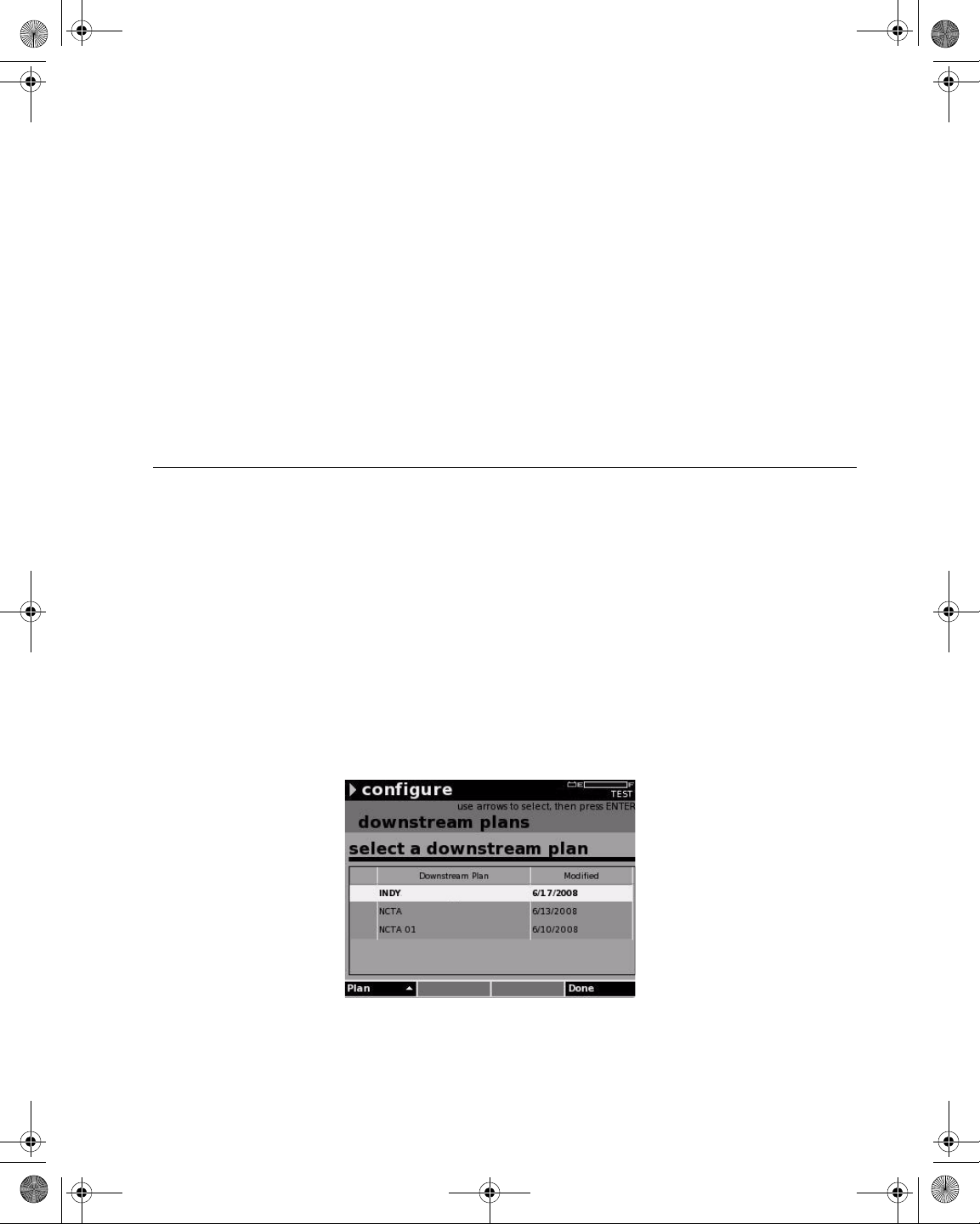
21128026 R001 DSAM Help User Guide.book Page 9 Thursday, February 5, 2009 2:02 PM
The blue shift key also shifts the functions of the softkeys to enable
access to the following:
–Level
– Miniscan
–Spectrum
–DOCSIS
Chapter 2 DSAM Navigation
The User Interface
Power Key
The User Interface
To display the Standby screen, press the green power key. The
Standby screen lets you place the DSAM in Standby mode up to 45
minutes, or turn the meter off.
The title bar at the top of the screen displays status indicators during
certain conditions. These indicator symbols flash to inform you that the
meter is:
– Conducting a repetitive measurement
– Paused (the measurement is not updated)
– Displaying a file
– In need of a charge
– Receiving a charge
– In need of service
Figure 5 Example: User Interface
DSAM Help User Guide Rev. 001 9
Page 50

21128026 R001 DSAM Help User Guide.book Page 10 Thursday, February 5, 2009 2:02 PM
Chapter 2 DSAM Navigation
Accessing Help
Active Channel
Plan Name
The active channel plan name is displayed in the far right corner of the
title bar, directly under the battery level indicator.
The battery symbol to the left of the battery level indicator begins to
flash when the battery charge condition is extremely low.
AC Power
Icons
A lightning bolt flashes when the unit is plugged in to AC power .
On the left side of the title bar (just to the left of the mode title), look for
the following symbols to appear when you are using the meter:
Table 9 Title Bar Icons
Name Symbol Description
Heartbeat Triangle
Pause Two thick vertical
lines
File File folder
Measurement
Failure
! An exclamation point indicates measurement failure. Check
A triangular “heartbeat” icon indicates the beginning of
each measurement cycle on screens wher e me a sur e ments are repetitive.
A pause icon (two thick vertical lines) indicates you
have enabled the pause function and the measurement is not updated.
A file icon indicates that a file is being viewed.
all of your settings and connections and try again. If the
exclamation point is still displayed, contact you nearest JDS
Uniphase Corporation Technical Assistance Center (TAC)
for further instructions.
Accessing Help
Introduction
10 DSAM Help User Guide Rev. 001
The DSAM is equipped with on-board Help designed to answer ma ny
of the questions you may have about the proper configuration of the
meter and the purpose and use of its measureme nt functions. Y ou can
access Help text as questions occur or easily review all of the text
associated with a particular function as a short tutorial before
attempting a task.
To access Help, press (Shift, ?) or (Shift, 5) on the alphanumeric
keypad (Figure 1 on page 2).
Page 51
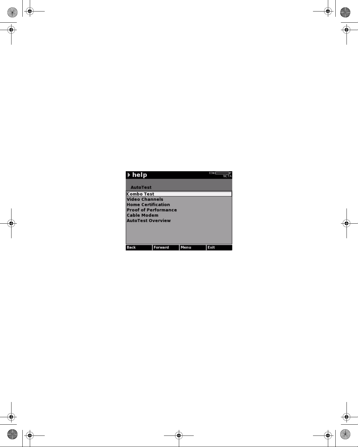
21128026 R001 DSAM Help User Guide.book Page 11 Thursday, February 5, 2009 2:02 PM
Chapter 2 DSAM Navigation
Accessing Help
Accessing Help
from a Mode Menu
When you access the Help system from one of the mode menus (such
as AutoT est or Measure), the DSAM displays a mode-level Help menu
that enables you to select the general topic you would like to research
within that mode (Figure 6 on page 11).
1 Using the arrow keys, select a topic.
2 Press ENTER.
The Help submode menu for that topic is displayed (Figure 7).
3 To specify the Help text you would like to review, use the arrow
keys again to select a topic.
4 Press ENTER.
Figure 6 Help Menu for AutoTest Mode
Accessing Help
from a Submode
DSAM Help User Guide Rev. 001 11
When you access the Help system from any screen within one of the
submodes (such as Combo AutoTest, DOCSIS, or Level), DSAM
displays a submode-level menu of specific Help topics (Figure 7).
1 Using the arrow keys, select a menu item.
2 Press ENTER.
Page 52
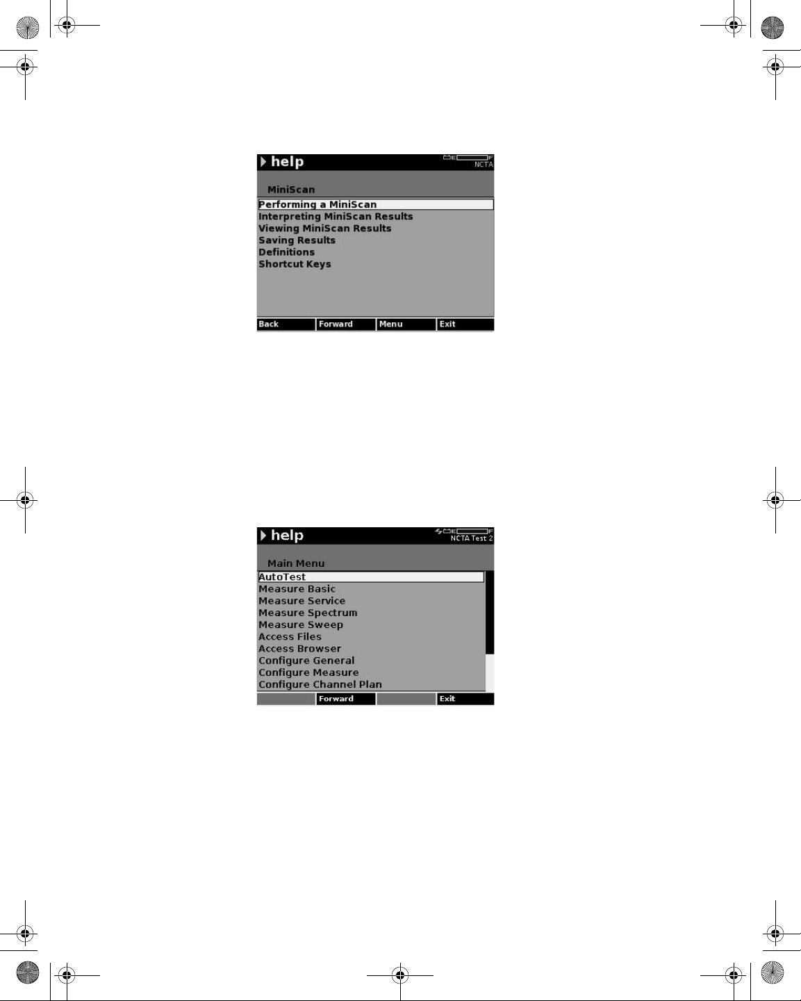
21128026 R001 DSAM Help User Guide.book Page 12 Thursday, February 5, 2009 2:02 PM
Chapter 2 DSAM Navigation
Accessing Help
Figure 7 Help Menu for AutoTest
Navigating Help
Use the Help screen softkeys (Figure 7 on page 12) to move forward
to the selected menu option or backward to the last viewed Help
screen.
1 To return to the beginning of the last active mode, press the Exit
softkey.
2 To display the Help main menu (Figure 8), use the Menu softkey.
Figure 8 Help Main Menu
12 DSAM Help User Guide Rev. 001
Page 53

21128026 R001 DSAM Help User Guide.book Page 13 Thursday, February 5, 2009 2:02 PM
Chapter3
Battery Installation
3
This chapter describes how to install and maintain a DSAM Product
Family Series battery. The topics discussed in this chapter are:
– “Installing and Maintaining the EZ Charge Battery” on page 14
– “Installing and Maintaining the Standard Capacity Battery” on
page 17
– “Making Additional Connections” on page 19
DSAM Help User Guide Rev. 001 13
Page 54
21128026 R001 DSAM Help User Guide.book Page 14 Thursday, February 5, 2009 2:02 PM
Chapter 3 Battery Installation
Installing and Maintaining the EZ Charge Battery
Installing and Maintaining the EZ Charge Battery
Installing the
Battery
Removing the
Battery
To install the battery
1 Hold the meter securely with the display screen facing away from
you and the keypad in the palm of your hand.
2 Holding the battery in your other hand with its label facing away
from you, rest the lower (contact) edge of the battery against the
raised edge at the bottom of the meter.
3 Gently lower the battery into the cavity of the meter until the top
edge of the battery latches into place.
To remove the battery
1 Ensure the power is off.
CAUTION INSTRUMENT DAMAGE
Failure to turn the power off before removing the batteries from the
DSAM Product Family Series Complete DSAM Meter Functionality
could damage internal components and/or corrupt th e software.
Always power down the unit before removing the batteries.
2 Hold the meter securely with the display screen facing away from
you and the keypad in the palm of your hand.
3 Press the release button (Figure 9) located directly above the
battery in the center of the back of the meter.
14 DSAM Help User Guide Rev. 001
Page 55
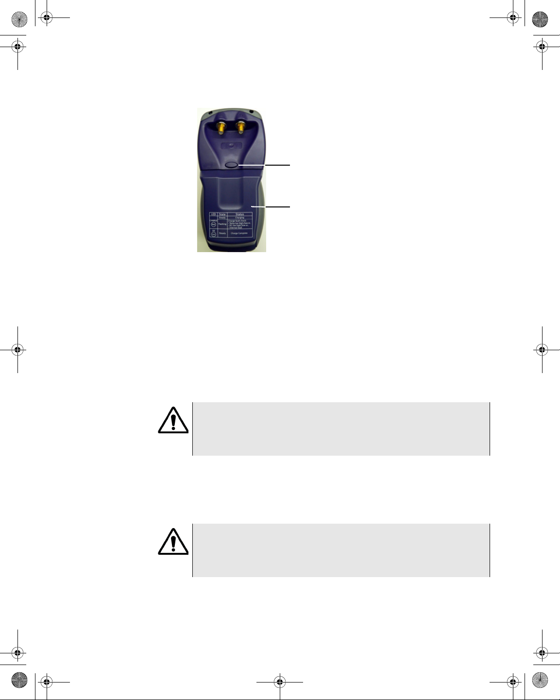
21128026 R001 DSAM Help User Guide.book Page 15 Thursday, February 5, 2009 2:02 PM
Battery Release
Button
Battery
Figure 9 DSAM Product Family Series Field Meter (Rear
View)
4 When released, gently pull the battery out of the cavity in the back
of the meter.
Chapter 3 Battery Installation
Installing and Maintaining the EZ Charge Battery
Connecting the
Power
Components
High Capacity Battery
to External Power
Connection
In addition to the battery , the following power components are supplied
with the DSAM Product Family Series:
– Charger module
– Power cord
IMPORTANT
Read all safety instructions in the front of this guide before attempting to power the meter or charge the battery (“Important Safety
Instructions” on page 304).
If a high capacity battery was provided with your DSAM you also
receive three additional power components with your DSAM Product
Family Series -- a 12 volt DC universal power supply module, a power
cord, and a 12-volt DC in-vehicle power cable.
IMPORTANT
Read all safety instructions in the front of this guide before attempting to power the meter or charge the battery (“Important Safety
Instructions” on page 304).
To connect the external power components (Figure 10 on page 16) to
the DSAM Product Family Series battery
DSAM Help User Guide Rev. 001 15
Page 56
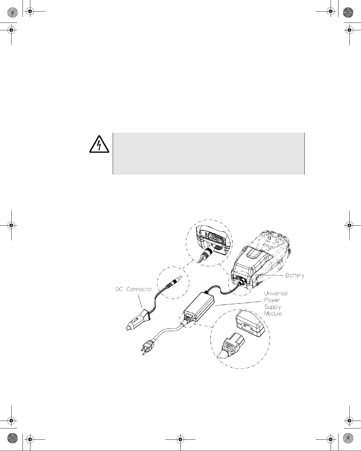
21128026 R001 DSAM Help User Guide.book Page 16 Thursday, February 5, 2009 2:02 PM
Chapter 3 Battery Installation
Installing and Maintaining the EZ Charge Battery
1 Align the 12 volt DC universal power supply module connector (or
DC connector) with the DC connection port in the battery.
2 Insert the connector into the connection port.
3 Align the power cord female connector with the 12 volt DC
universal power supply connection port.
4 Insert the connector into the connection port.
WARNING ELECTRICAL SHOCK
Electrical shock may result in serious injury or death. Be sure the
AC cord is connected to the correct voltage mains. Do not use outdoors or in wet locations. Use only the universal power supply supplied with the test set.
5 Insert power cord male plug to an AC power source when you are
ready to power the meter or charge the battery. (If you are using
the DC connector, connect it to an appropriate 12-volt DC power
source.)
Figure 10 High Capacity External Power Components
16 DSAM Help User Guide Rev. 001
Page 57
21128026 R001 DSAM Help User Guide.book Page 17 Thursday, February 5, 2009 2:02 PM
Installing and Maintaining the Standard Capacity Battery
Chapter 3 Battery Installation
Connecting the
RF Cable
To conduct measurements with your DSAM Product Family Series,
connect the RF cable of the system you are servicing to the RF
connection port on the back panel of the meter.
Installing and Maintaining the Standard Capacity Battery
Installing the
Battery
Removing the
Battery
To install the battery
1 Hold the meter securely with the display screen facing away from
you and the keypad in the palm of your hand.
2 Holding the battery in your other hand with its label facing away
from you, rest the lower (contact) edge of the battery against the
raised edge at the bottom of the meter.
3 Gently lower the battery into the cavity of the meter until the top
edge of the battery latches into place.
To remove the batter y
1 Hold the DSAM securely with the display screen facing away from
you and the keypad in the palm of your hand.
2 Press the release button located directly above the battery in the
center of the back of the meter.
3 Gently pull the battery out of the cavity.
NOTE
For information about optimizing battery life, refer to “Battery Con-
servation” on page 32.
Connecting the
Power
Components
(Standard
Capacity Battery)
DSAM Help User Guide Rev. 001 17
In addition to the battery , the following power components are supplied
with the DSAM Product Family Series:
– Charger module
– Universal power supply module
– Power cord
– 12-volt DC in-vehicle power cable
Page 58

21128026 R001 DSAM Help User Guide.book Page 18 Thursday, February 5, 2009 2:02 PM
Chapter 3 Battery Installation
Installing and Maintaining the Standard Capacity Battery
IMPORTANT
Read all safety instructions in the front of this guide before attempting to power the meter or charge the battery (“Important Safety
Instructions” on page 304).
Figure 11 Standard Capacity External Power Components
Connect the power components in the manner displayed in Figure 10
on page 16.
18 DSAM Help User Guide Rev. 001
Page 59
21128026 R001 DSAM Help User Guide.book Page 19 Thursday, February 5, 2009 2:02 PM
Follow these steps to connect the power components to the DSAM
Product Family Series battery (the battery can be in or out of the
meter):
1 Align the tabs of the charger module connector to the slots in the
battery and gently insert the connector tabs into the battery slots.
2 Align the universal power supply module connector (or DC
connector) with the DC connection port in the charger module and
gently insert the connector into the connection port.
3 Align the power cord connector with the universal power supply
connection port and gently insert the connector into the connection port. Connect the power cord plug to an AC power source
when you are ready to power the meter or charge the battery. (If
you are using the DC connector, connect it to an appropriate 12volt DC power source.)
Chapter 3 Battery Installation
Making Additional Connections
WARNING ELECTRICAL SHOCK
Electrical shock may resul t in serious injury or death. Be sure the
AC cord is connected to the correct voltage mains. Do not use outdoors or in wet locations. Use only the universal power supply supplied with the test set.
Making Additional Connections
Use the Ethernet port located on the top of the meter to clone settings
with other DSAM Product Family Series meters (“Clone” on page 48)
or to synchronize your data with optional TPP utility software
(“Synchronization” on page 106).
The headphone jack and USB port are locate d on the top of the meter .
The headphone jack is for V oIP and the USB po rt is for future features.
DSAM Help User Guide Rev. 001 19
Page 60

21128026 R001 DSAM Help User Guide.book Page 20 Thursday, February 5, 2009 2:02 PM
Chapter 3 Battery Installation
Making Additional Connections
20 DSAM Help User Guide Rev. 001
Page 61

21128026 R001 DSAM Help User Guide.book Page 21 Thursday, February 5, 2009 2:02 PM
Chapter4
Powering the DSAM
4
This chapter describes the test results that you gather when running a
test. Test results described in this chapter are as follows:
– “Powering the Meter” on page 22
DSAM Help User Guide Rev. 001 21
Page 62

21128026 R001 DSAM Help User Guide.book Page 22 Thursday, February 5, 2009 2:02 PM
Chapter 4 Powering the DSAM
Powering the Meter
Powering the Meter
IMPORTANT
Read all safety instructions in the front of this guide before attempting to power the meter or charge the battery (“Important Safety
Instructions” on page 304).
Choosing a Power
Option
Charging the
Battery
There are three ways to provide power to your DSAM Product Family
Series. Select the method that best suits your working conditions:
– DC power from the universal power supply connected to an AC
power source
– DC power from the battery alone
– DC power using the 12-volt DC in-vehicle cable connected to 12-
volt DC power source
With the power components properly connected, the DSAM Product
Family Series battery can be charged when outside of the me te r or
when installed in the meter.
NOTE
You can power the DSAM and recharge the batteries at the same
time. If you do not want to interrupt the current test, you may leave
the power on and connect the AC power adaptor.
1 For typical battery charging (fast charge or maximum capacity)
and normal operational values.
Table 10 Battery Charge and Operation Values
Item Charge Time
High Capacity Battery 11 AH (Amp Hour)
Fast Charge Period > 7.0 Hours
Normal Operation 5.0 Hours typical
Complete Charge Approximately 10 to 12 Hours
Standard Capacity Battery 6.6 AH (Amp Hour)
Fast Charge Period > 4.0 Hours
22 DSAM Help User Guide Rev. 001
Page 63

21128026 R001 DSAM Help User Guide.book Page 23 Thursday, February 5, 2009 2:02 PM
Table 10 Battery Charge and Operation Values (Continued)
Item Charge Time
Normal Operation 3.0 Hours typical
Complete Charge Approximately 6 to 7 Hours
2 For standard capacity battery charge LED indications, refer to
Table 11 on page 23.
OR
3 For high capacity battery charge LED indications, refer to Table 12
on page 25.
The charging time is be the same whether the power is on or off.
When you power the meter directly with an AC or a DC power
source, this source automatically charges the battery while
providing power on a separate path with no degradation to the
meter’s direct power. When the battery is fully charged, the
charger module provides a maintenance charge from the power
source. The charger module automatically identifies the type of
battery being charged. No battery configuration is required.
Chapter 4 Powering the DSAM
Powering the Meter
Understanding the
Standard Capacity
Battery LED’s
There are two LED indicator lights on your DSAM Product Family
Series standard capacity charger module -- the “Power” LED and the
“Charge” LED.
The green “Power” LED illuminates to indicate that the charger module
is receiving power.
The “Charge” LED illuminates in red, green, or orange to indicate the
present battery and charge condition. It may remain on constantly, or
it may begin to flash. T o interpret the “Charge” L ED indications, review
Table 11.
Table 11 Standard Capacity Charge LED Indications
LED color LED activity Battery and charge condition
Red On
(constant)
DSAM Help User Guide Rev. 001 23
Charger module is in fast charge
mode; maximum charge is delivered
to battery
Page 64
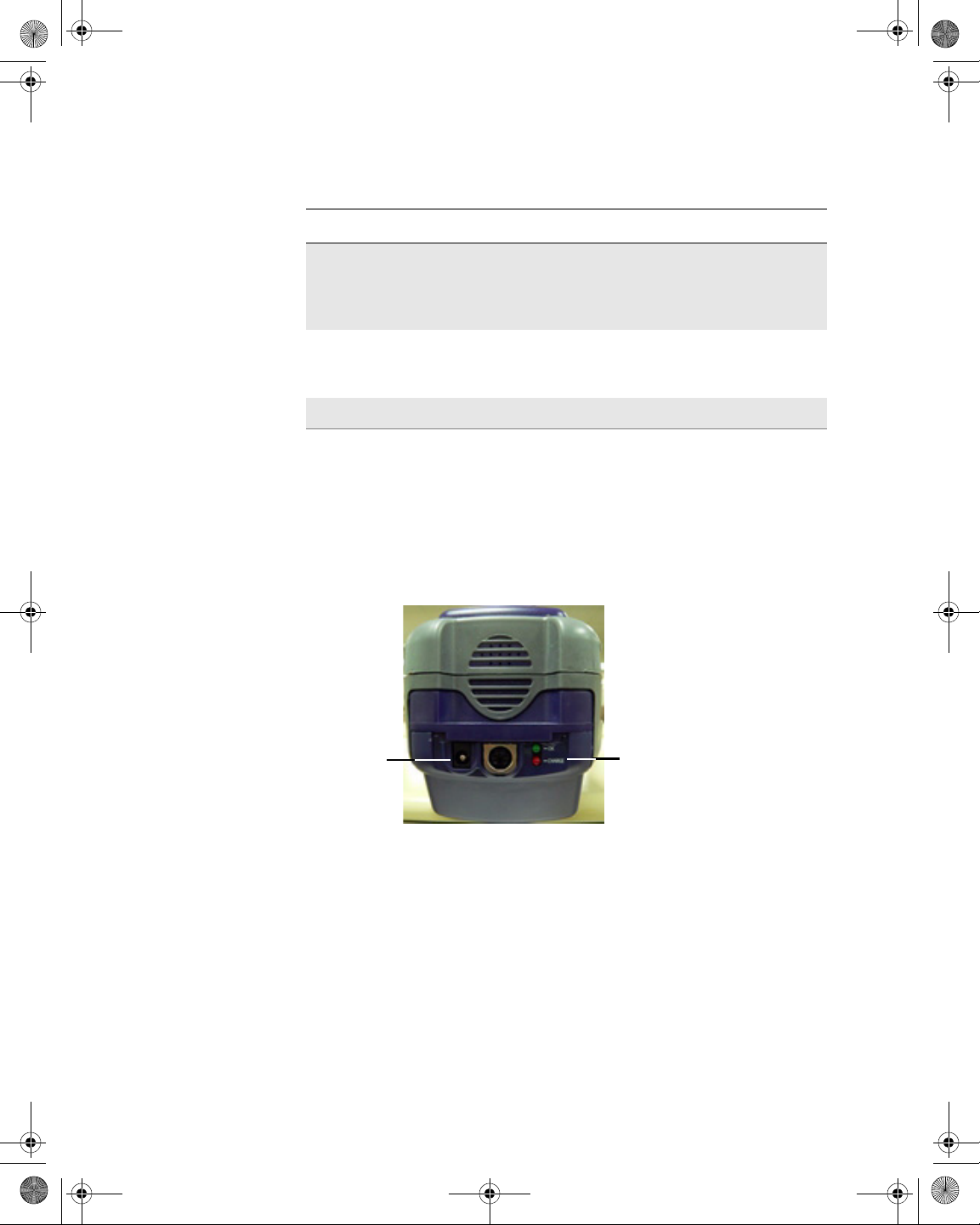
21128026 R001 DSAM Help User Guide.book Page 24 Thursday, February 5, 2009 2:02 PM
Chapter 4 Powering the DSAM
Powering the Meter
Table 11 Standard Capacity Charge LED Indications
LED color LED activity Battery and charge condition
Understanding the
High Capacity
Battery LED’s
Green On
(constant)
Red Flashing Battery-related error or defect
Orange Flashing DC input voltage is out of range.
Fast charge cycle is complete; battery
is ready for use and in maintenance
charge mode while attached to the
charger module
detected; min/max cell voltage or battery temperature is out of range)
For information about the charger module’s specifications, see
Table 48 on page 302.
There are two LED indicator lights located on the bo ttom of yo ur hig h
capacity DSAM Product Family Series battery (refer to Figure 12 on
page 24) -- the red “CHARGE” LED and the green “OK” LED.
12 Volt
DC Port
Charge
Indicator
LEDS
Figure 12 DSAM Product Family Series Field Meter (Bottom
View)
The green “OK” LED illuminates to indicate that the battery is
completely charged.
The red “CHARGE” LED illuminates to indicate the present charge
condition. Under normal charging conditions, this LED should remain
on constantly . A flashing LED is indicative of a fault conditio n. To interpret the “CHARGE” LED indications, review Table 12.
24 DSAM Help User Guide Rev. 001
Page 65
21128026 R001 DSAM Help User Guide.book Page 25 Thursday, February 5, 2009 2:02 PM
Table 12 High Capacity Charge LED Indications
LED color State Battery and charge condition
Chapter 4 Powering the DSAM
Powering the Meter
Charging
Temperature
Range
Red
(CHARGE)
Green (OK) Steady Charge Complete
Steady Charging
Flashing Charge fault check:
Temp too high/low or,
DC too high/low or,
Internal fault
For information about the charger module’s specifications, see
Table 48 on page 302.
Y our DSAM Product Family Seri es charger module does not allow the
charge mode to begin if the battery temperature is not within a safe
range for charging. To begin and maintain the charge mode, the
battery temperature should be approximately between 0° C (32° F)
and 50° C (122° F). The charge mode automatically resumes when the
battery temperature returns within this range.
DSAM Help User Guide Rev. 001 25
Page 66

21128026 R001 DSAM Help User Guide.book Page 26 Thursday, February 5, 2009 2:02 PM
Chapter 4 Powering the DSAM
Powering the Meter
26 DSAM Help User Guide Rev. 001
Page 67

21128026 R001 DSAM Help User Guide.book Page 27 Thursday, February 5, 2009 2:02 PM
Chapter5
Configuring the Meter
5
This chapter describes the functionality of the instrument. Topics
discussed in this chapter are as follows:
– “Overview” on page 28
– “Configure – General Tab” on page 28
– “Configure – Measure Tab” on page 55
– “Configure – Channel Plan Tab” on page 77
– “Configure – Access Tab” on page 96
DSAM Help User Guide Rev. 001 27
Page 68

21128026 R001 DSAM Help User Guide.book Page 28 Thursday, February 5, 2009 2:02 PM
Chapter 5 Configuring the Meter
Overview
Overview
This chapter describes general meter functionality configuration. Later
chapters in this manual describe the AutoTest and Measure modes
and the corresponding configuration information for each mode.
To take full advantage of the many features your DSAM Product
Family Series offers, be sure to properly configure the meter to
respond effectively to your working conditions and meet your data
management needs.
Configure – General Tab
The Configure mode – General tab enables you to edit the following
configuration areas for the DSAM:
Contrast
– Adjust contrast
– Adjust sounds
– Optimize battery life
– Enter your personal information
– Set date and time
– Configure printer
– Configure Ethernet
– Configure RF network
– Configure ports
– Set locale preferences
– Administer security
– Perfo rm me te r ma in te na nc e
– Clone settings with other DSAM Product Family Series meters
– Run meter diagnostics
The contrast adjustment function provides two modes of contrast
adjustment — Auto and Manual.
28 DSAM Help User Guide Rev. 001
Page 69
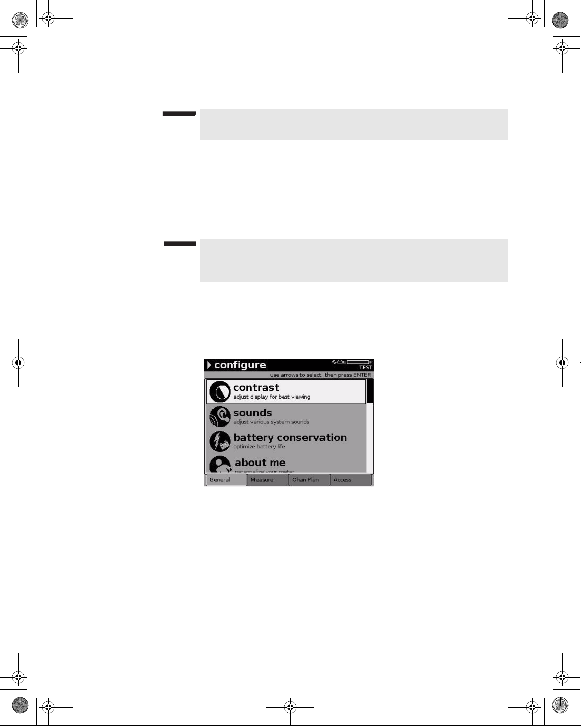
21128026 R001 DSAM Help User Guide.book Page 29 Thursday, February 5, 2009 2:02 PM
NOTE
Contrast is not applicable to DSAM
– Auto adjustment provides a limited contrast adjustment based on
the sensed temperature range.
– Manual adjustment provides full contrast adjustment across the
entire operational temperature range (0 to +120 degrees Fahrenheit or -20 to +50 degrees Celsius). The factory default for screen
contrast is 50%.
NOTE
When working in extreme temperatures, JDSU recommends using
Manual mode.
Chapter 5 Configuring the Meter
Configure – General Tab
XT
models.
Configuring Screen
Contrast
To configure screen cont ra st
1 Press Configure.
2 Press the General softkey.
Figure 13 Configure – General Tab: Contrast Adjustment
3 Using the arrow keys, select Contrast.
4 Press ENTER.
DSAM Help User Guide Rev. 001 29
Page 70
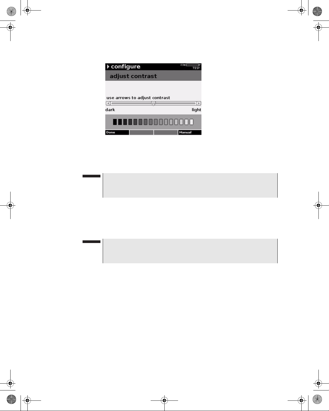
21128026 R001 DSAM Help User Guide.book Page 30 Thursday, February 5, 2009 2:02 PM
Chapter 5 Configuring the Meter
Configure – General Tab
Figure 14 Configure – Adjust Contrast
5 To switch between contr ast modes, press the Manual/Auto
softkey.
NOTE
When the Auto softkey is displayed, the DSAM contrast function is
in Manual mode and vice versa. The factory default mode is Auto.
6 Adjust the degree of difference between the lightest and darkest
areas of the screen by using the left and right arrow keys to move
the contrast indicator (slider).
The Auto mode allows a limited amount of adjustment.
NOTE
To perform a repetitive contrast adjustment, press and hold the left
or right arrow key.
7 Press the Done softkey.
Sound
Use the Adjust Sounds screen to change the volume of sounds and
the sensitivity of the microphone.
Configuring Sounds
To configure sounds
1 Press Configure.
2 Press the General softkey.
30 DSAM Help User Guide Rev. 001
Page 71
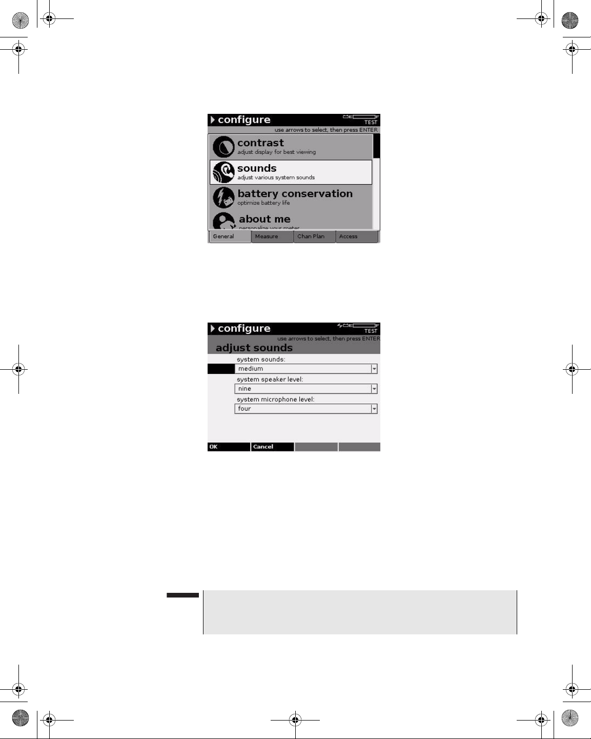
21128026 R001 DSAM Help User Guide.book Page 31 Thursday, February 5, 2009 2:02 PM
Figure 15 Configure – General Tab: Sounds
3 Using the arrow keys, select Sounds.
4 Press ENTER.
Chapter 5 Configuring the Meter
Configure – General Tab
Figure 16 Configure – Adjust Sounds
5 Using the arrow keys, select the parameter you want to edit.
6 Press ENTER.
7 Using the arrow keys, select an option.
8 Press ENTER.
9 Press the OK softkey.
NOTE
Press (Shift, 3) to access the Adjust Sounds screen from a measurement screen.
DSAM Help User Guide Rev. 001 31
Page 72
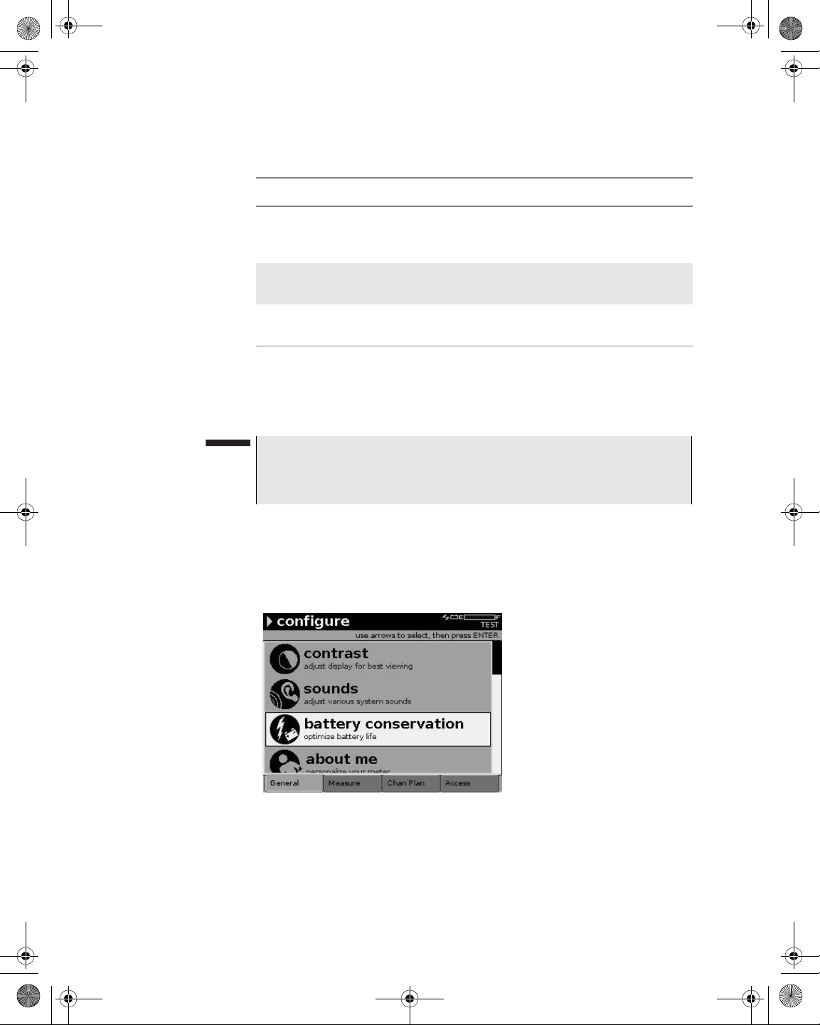
21128026 R001 DSAM Help User Guide.book Page 32 Thursday, February 5, 2009 2:02 PM
Chapter 5 Configuring the Meter
Configure – General Tab
Table 13 Sound Parameters
Name Description
System Sounds The sound level of beeps and other noises made by
the meter. Valid options are Off, Quiet, Medium and
Loud. The default option is Medium.
Battery
Conservation
Configuring Battery
Conservation
System Speaker
Level
System Microphone Level
The sound level of the speaker. Valid options are
one through ten. The default option is nine.
The sensitivity of the microphone. Valid options are
one through ten. The default option is four.
By configuring the battery conservation parameters for the meter and
backlight shutdown, you can optimize your most recent batter y charge
to suit your work practices.
NOTE
The factory default time for meter shut off is 10 minutes.
The factory default time for backlight shut off is “always.”
To configure battery conservation settings
1 Press Configure.
2 Press the General softkey.
Figure 17 Configure – General Tab: Battery Conservation
3 Using the arrow keys, select Battery Conservation.
4 Press ENTER.
32 DSAM Help User Guide Rev. 001
Page 73
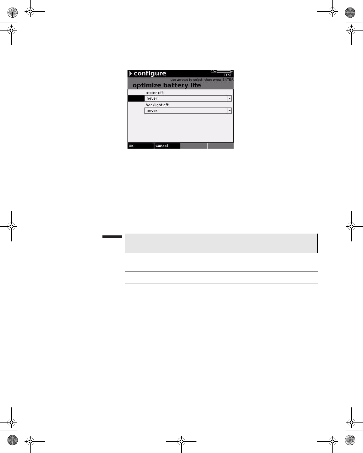
21128026 R001 DSAM Help User Guide.book Page 33 Thursday, February 5, 2009 2:02 PM
Figure 18 Configure – Optimize Battery Life
5 Using the arrow keys, select the parameter you want to edit.
6 Press ENTER.
Chapter 5 Configuring the Meter
Configure – General Tab
7 Using the arrow keys, select an option.
8 Press ENTER.
9 Press the OK softkey.
NOTE
Press Shift, Shift to turn the backlight on or off.
Table 14 Battery Conservation Parameters
Name Description
Meter Off The number of minutes of non-activity before the
meter powers off. Valid options are:
– After 5 minutes
– After 10 minutes
– After 15 minutes
– Never
The default option is After 15 minutes.
DSAM Help User Guide Rev. 001 33
Page 74

21128026 R001 DSAM Help User Guide.book Page 34 Thursday, February 5, 2009 2:02 PM
Chapter 5 Configuring the Meter
Configure – General Tab
Table 14 Battery Conservation Parameters (Continued)
Name Description
Backlight Off The number of seconds of non-activity before the
screen dims. Valid options are:
– Always
– After 5 seconds
– After 15 seconds
– After 30 seconds
– Never
The default option is After 15 seconds.
About Me
Configuring “About
Me”
You can personalize your meter by entering your name on the Enter
Your Info screen. (The Employee ID is set by TPP.)
To personalize your meter
1 Press Configure.
2 Press the General softkey.
Figure 19 Configure – General Tab: About Me
3 Using the arrow keys, select About Me.
4 Press ENTER.
34 DSAM Help User Guide Rev. 001
Page 75

21128026 R001 DSAM Help User Guide.book Page 35 Thursday, February 5, 2009 2:02 PM
Figure 20 Configure – Enter Your Info
5 Using the arrow keys, select My Name.
6 Press ENTER.
Chapter 5 Configuring the Meter
Configure – General Tab
Date and Time
7 Using the arrow keys and the alphanumeric keypad, edit the
value.
8 Press ENTER.
NOTE
Press the “1” key repeatedly to access a variety of special characters (- + # @ * etc.), then press ENTER.
9 Press the OK softkey.
Table 15 “About Me” Parameters
Name Description
My Name Your name as it will appear in TPP.
My Employee ID Your employee ID as assigned in TPP.
Use the Set Date and Time screen to set the current date and time.
NOTE
The Set Date and Time screen may be locked by TPP. Also, TPP
may be configured to update the date and time upon synchronization.
DSAM Help User Guide Rev. 001 35
Page 76

21128026 R001 DSAM Help User Guide.book Page 36 Thursday, February 5, 2009 2:02 PM
Chapter 5 Configuring the Meter
Configure – General Tab
Configuring Date and
Time
To set the meter date and time
1 Press Configure.
2 Press the General softkey.
Figure 21 Configure – General Tab: Date and Time
3 Using the arrow keys, select Date and Time.
4 Press ENTER.
5 Using the arrow keys, select the parameter you want to edit.
6 Press ENTER.
Figure 22 Configure – Set Date and Time
7 Using the arrow keys and the alphanumeric keypad, edit the
value.
8 Press ENTER.
36 DSAM Help User Guide Rev. 001
Page 77

21128026 R001 DSAM Help User Guide.book Page 37 Thursday, February 5, 2009 2:02 PM
NOTE
To change the date format see “Regional Preferences” on page 43.
9 Press the OK softkey.
Table 16 Date and Time Parameters
Name Description
Current Date The current date.
Current Time The current time in 24-hour format.
Chapter 5 Configuring the Meter
Configure – General Tab
Printer
Configuring the
Printer
Use the Configure Printer screen to select a printer or edit the lines
printed per page.
To configure the printer
1 Press Configure.
2 Press the General softkey.
Figure 23 Configure – General Tab: Printer
3 Using the arrow keys, select Printer.
4 Press ENTER.
DSAM Help User Guide Rev. 001 37
Page 78

21128026 R001 DSAM Help User Guide.book Page 38 Thursday, February 5, 2009 2:02 PM
Chapter 5 Configuring the Meter
Configure – General Tab
Figure 24 Configure – Configure Printer
5 Using the arrow keys, select the parameter you want to edit.
6 Press ENTER.
Ethernet Network
7 Using the arrow keys and the alphanumeric keypad, edit the
value.
8 Press ENTER.
9 Press the OK softkey.
Table 17 Printer Parameters
Name Description
Type The type of printer. Options are Epson (serial) and
Citizen (serial). The default option is Epson (serial).
Lines Per Page The number of lines printed per page. The default
value is 66. The maximum value for a Citizen printer
is 255.
NOTE
Only serial printers are supported.
The DSAM uses a DHCP (Dynamic Host Configuration Protocol)
server as its default network setting. Use the Configure Ethernet
Network screen to specify an alternate IP address, subnet mask,
default gateway and DNS server.
38 DSAM Help User Guide Rev. 001
Page 79

21128026 R001 DSAM Help User Guide.book Page 39 Thursday, February 5, 2009 2:02 PM
Chapter 5 Configuring the Meter
Configure – General Tab
Configuring Ethernet
Settings
To configure Ethernet settings
1 Press Configure.
2 Press the General softkey.
Figure 25 Configure – General Tab: Ethernet Network
3 Using the arrow keys, select Ethernet Network.
4 Press ENTER.
Figure 26 Configure Mode – Configure Ethernet
5 Using the arrow keys, select the parameter you want to edit.
6 Press ENTER.
7 Using the arrow keys and the alphanumeric keypad, edit the
value.
8 Press ENTER.
DSAM Help User Guide Rev. 001 39
Page 80
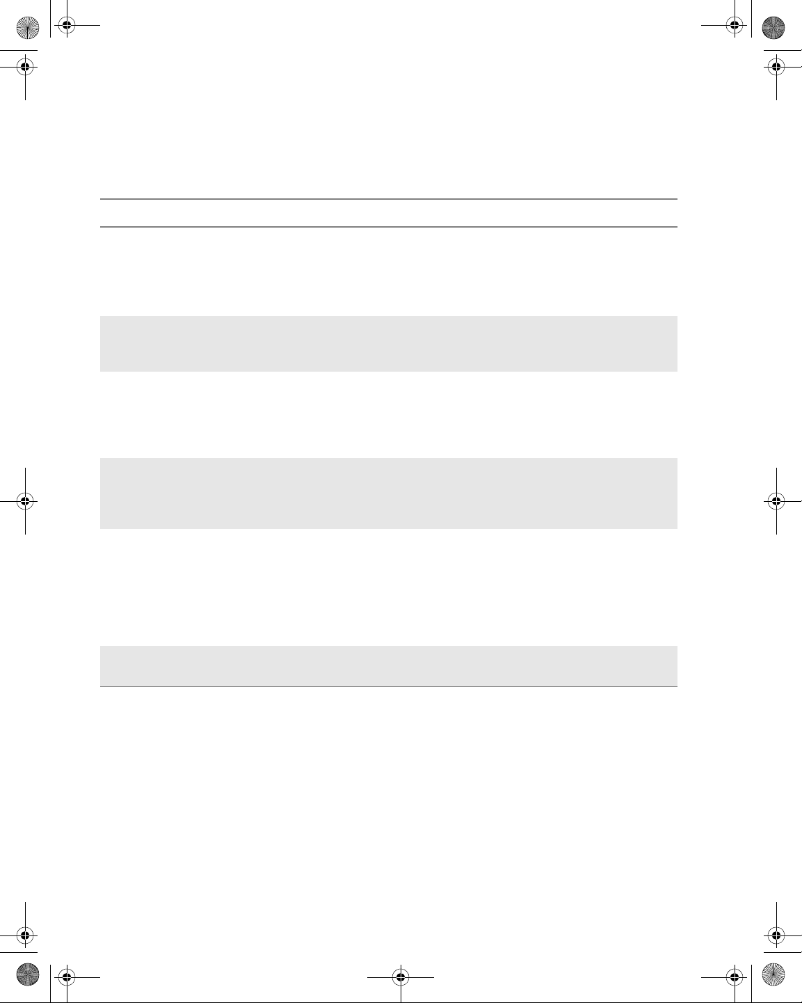
21128026 R001 DSAM Help User Guide.book Page 40 Thursday, February 5, 2009 2:02 PM
Chapter 5 Configuring the Meter
Configure – General Tab
9 Press the OK softkey.
Table 18 Ethernet Settings Parameters
Parameter Description
Obtain IP
Address From
Where the meter should obtain the IP address from. Options are DHCP Server
and Let Me Specify Below . The default option is DHCP Server. All IP addresses
are numeric only.
NOTE: When the meter is configured for DHCP, no additional configura-
tion is required.
IP Address The numerical identification (logical address) assigned to the meter that identi-
fies it to the network. The valid range for this value is 0.0.0.0 to
255.255.255.255. All IP addresses are numeric only.
Subnet Mask The subnet mask for the meter. A subnet mask is used in the IP addressing
system which divides the IP address in two parts: the network part and the host
part. The subnet mask works by masking out the network part from the full IP
address. The valid range for this value is 0.0.0.0 to 255.255.255.255. All IP
addresses are numeric only.
Default Gateway The default gateway for the meter. A default gateway is a node (such as a
router) on a computer network that serves as an access point to another network. The valid range for this value is 0.0.0.0 to 255.255.255.255. All IP
addresses are numeric only.
DNS Server The DNS server for the meter. The Domain Name System (DNS) associates
various information with domain names; most importantly, it serves as the
“phone book” for the Internet by translating human-readable computer host
names, e.g. www.example.com, into IP addresses, for example,
192.168.0.100, which networking equipment needs to deliver informatio n.The
valid range for this value is 0.0.0.0 to 255.255.255.255. All IP addresses are
numeric only.
DHCP Option-12
Computer Name
RF Network
The DHCP name of the meter on the network.
This meter uses a DHCP (Dynamic Host Configuration Protocol)
server as its default network setting. Use the Configure RF Network
screen to specify an alternate IP address, subnet mask, default
gateway and DNS server.
Configuring RF
Network Settings
To configure RF network settings
1 Press Configure.
2 Press the General softkey.
40 DSAM Help User Guide Rev. 001
Page 81
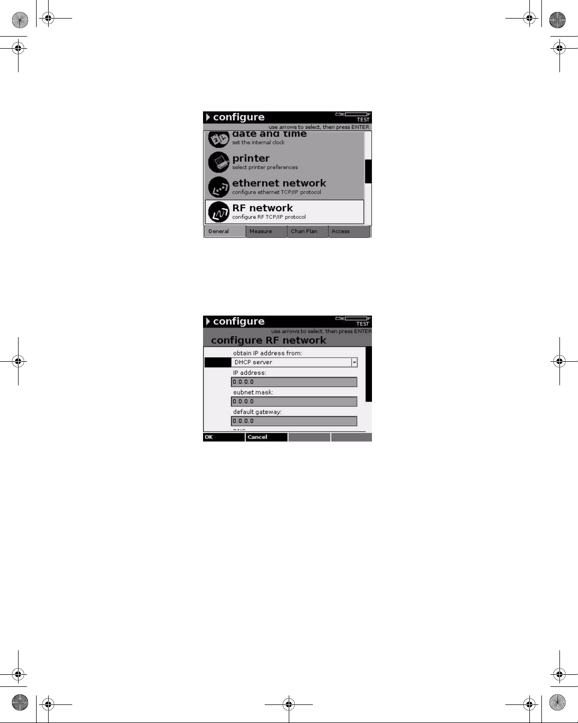
21128026 R001 DSAM Help User Guide.book Page 41 Thursday, February 5, 2009 2:02 PM
Figure 27 Configure – General Tab: RF Network
3 Using the arrow keys, select RF Network.
4 Press ENTER.
Chapter 5 Configuring the Meter
Configure – General Tab
Figure 28 Configure – Configure RF Network
5 Using the arrow keys, select the parameter you want to edit.
6 Press ENTER.
7 Using the arrow keys and the alphanumeric keypad, edit the
value.
8 Press ENTER.
9 Press the OK softkey.
RF Network Parameters
DSAM Help User Guide Rev. 001 41
RF network parameters are the same as Ethernet parameters. Refer
to “Ethernet Settings Parameters” on page 40.
Page 82
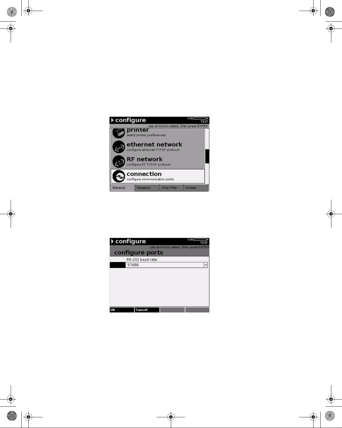
21128026 R001 DSAM Help User Guide.book Page 42 Thursday, February 5, 2009 2:02 PM
Chapter 5 Configuring the Meter
Configure – General Tab
Port Connections
Configuring
Connection Settings
This screen enables you to configure the baud rate of the RS-232 port.
To configure connection settings
1 Press Configure.
2 Press the General softkey.
Figure 29 Configure – General Tab: Connection
3 Using the arrow keys, select Connection.
4 Press ENTER.
Figure 30 Configure – Configure Ports
5 Press ENTER.
6 Using the arrow keys, select an option.
7 Press ENTER.
42 DSAM Help User Guide Rev. 001
Page 83
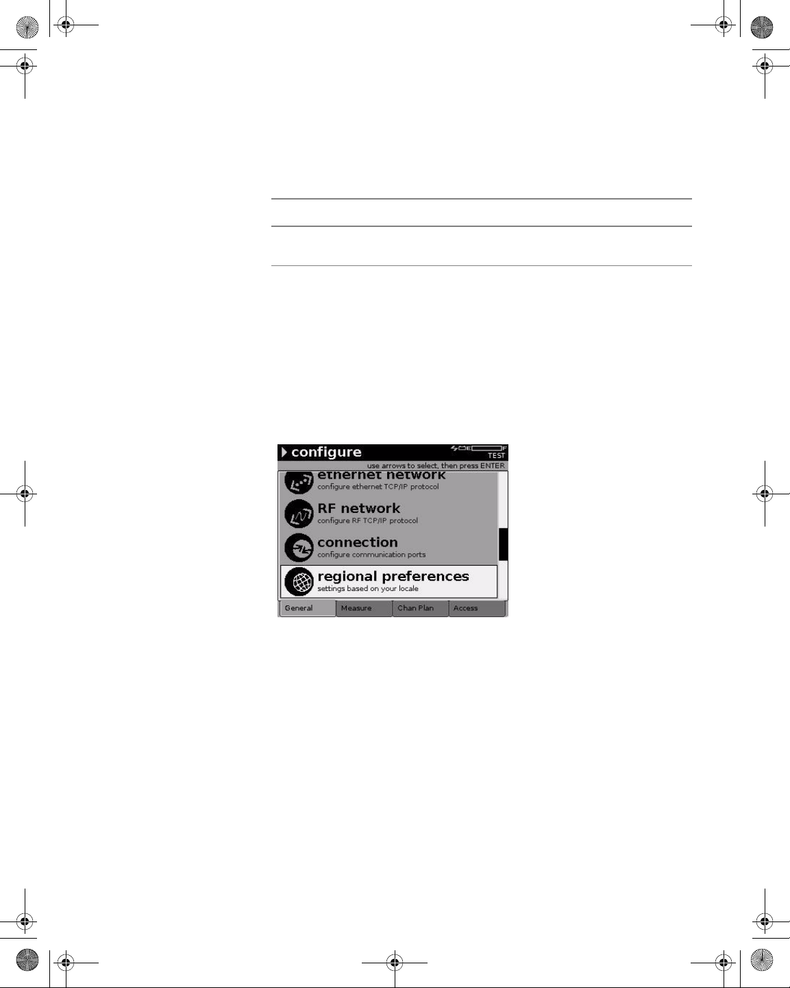
21128026 R001 DSAM Help User Guide.book Page 43 Thursday, February 5, 2009 2:02 PM
8 Press the OK softkey.
Table 19 Connection Parameters
Name Description
Chapter 5 Configuring the Meter
Configure – General Tab
Regional
Preferences
Configuring Regional
Preferences
RS-232 Baud
Rate
The signaling rate of the RS-232 port. The default
option is 57600.
Use the Set Local Preferences screen to specify the type of language,
date format, signal level units, temperature units, and digital performance units.
To configure regional settings
1 Press Configure.
2 Press the General softkey.
Figure 31 Configure – General Tab: Regional Preferences
3 Using the arrow keys, select Regional Preferences.
4 Press ENTER.
DSAM Help User Guide Rev. 001 43
Page 84
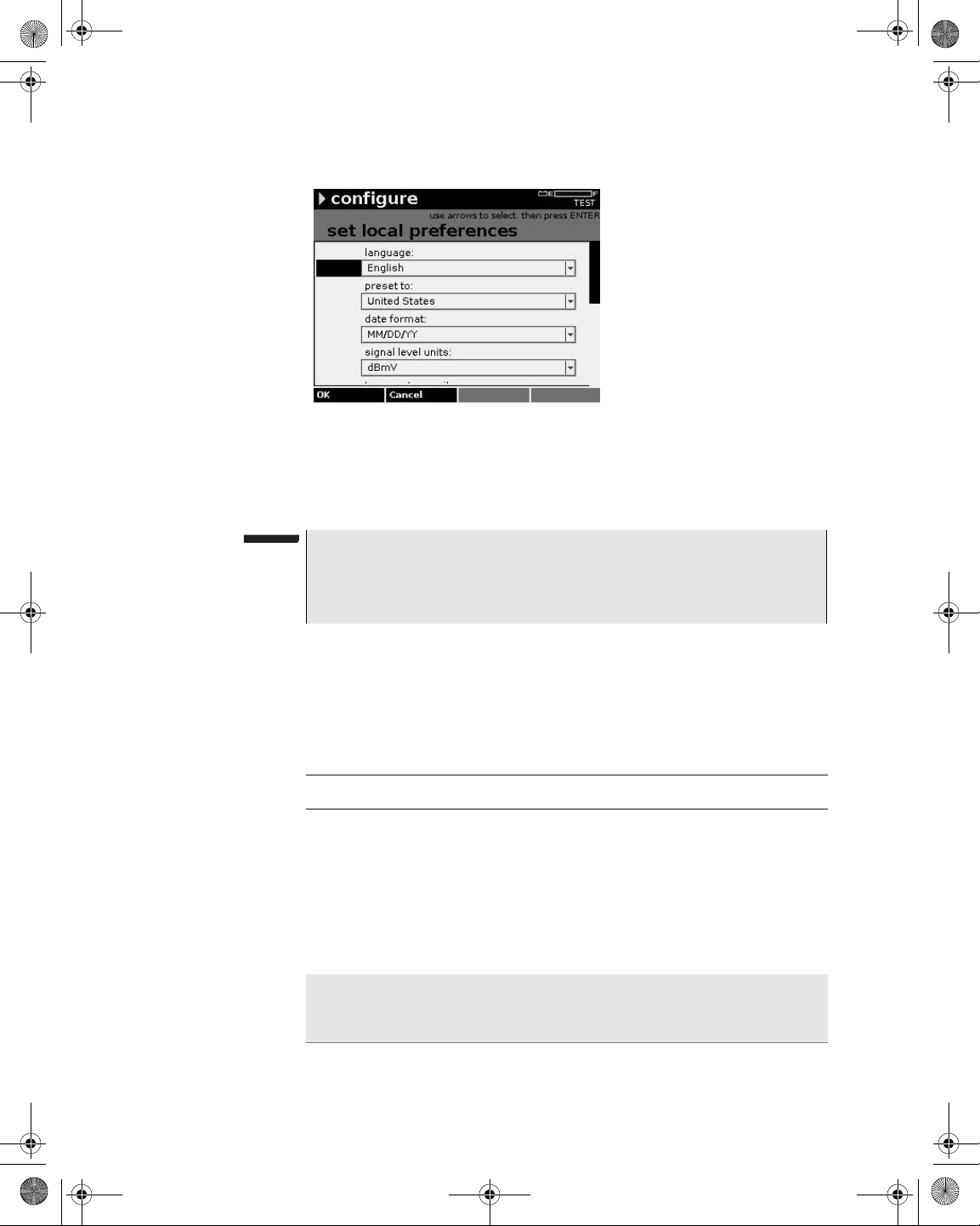
21128026 R001 DSAM Help User Guide.book Page 44 Thursday, February 5, 2009 2:02 PM
Chapter 5 Configuring the Meter
Configure – General Tab
Figure 32 Configure – Set Local Preferences
5 Using the arrow keys, select the parameter you want to edit.
6 Press ENTER.
NOTE
You can save time by choosing the Preset To parameter first. The
Preset To value determines the corresponding defaults for the other
options.
7 Using the arrow keys, select an option.
8 Press ENTER.
9 Press the OK softkey.
Table 20 Regional Preferences Parameters
Name Description
Language The language displayed in the user interface.
Options are English, French, German and Spanish.
(Other languages may be installed on your particular meter by the factory.) The default option is English.
NOTE:
ing the language for the new language to take
effect.
Preset To The country where the meter is used. The Preset To
value determines the corresponding defaults for the
other options. The default option is United States.
You must restart the meter after chang-
44 DSAM Help User Guide Rev. 001
Page 85
21128026 R001 DSAM Help User Guide.book Page 45 Thursday, February 5, 2009 2:02 PM
Table 20 Regional Preferences Parameters (Continued)
Name Description
Date Format The syntax for displaying dates in the user inter-
face. The default option is MM/DD/YY.
Chapter 5 Configuring the Meter
Configure – General Tab
Security
Signal Level
Units
Temperature
Units
Distance Units The unit of measure used to select the distant or
Digital Performance Units
Hum Result Units The unit of measure used to select th e Hum
Hum Power Grid The frequency at which the electric network oper-
The unit of measure used to select the signal level
unit options. Valid options are dBmV, dBµV, and
dBm. The default option is dBmV.
The unit of measure used to select the temperature
options. Valid options are Fahrenheit or Celsius.
The default option is Fahrenheit.
length options. Valid options are Feet or Meters.
The default option is Feet.
The unit of measure used to select the performance
rating options. Valid options are MER (modulation
error ratio) or EVM (error vector magnitude – or
MER presented in percentage format). The default
option is MER.
options. Valid options are Percent (%) or Decibels
(dB). The default option is Percent (%).
ates. Valid options are 50 Hz and 60 Hz. The default
option is 60 Hz.
Use the Administer Security screen to set your perso nal identification
number (PIN) or to enable/disable security protection on the meter.
When security protection is enabled, you must enter your PIN to select
or modify a channel plan, and to select or modify limit sets.
Setting Your PIN
To set your PIN
1 Press Configure.
2 Press the General softkey.
DSAM Help User Guide Rev. 001 45
Page 86

21128026 R001 DSAM Help User Guide.book Page 46 Thursday, February 5, 2009 2:02 PM
Chapter 5 Configuring the Meter
Configure – General Tab
Figure 33 Configure – General Tab: Security
3 Using the arrow keys, select Security.
4 Press ENTER.
Figure 34 Configure – Administer Security
5 Using the arrow keys, select Set your personal identification
number (PIN).
6 Press ENTER.
7 Type your four-digit PIN using only digits 0 through 9.
8 Press the Next softkey.
9 Type your PIN again to confirm it.
10 Press the OK softkey.
46 DSAM Help User Guide Rev. 001
Page 87
21128026 R001 DSAM Help User Guide.book Page 47 Thursday, February 5, 2009 2:02 PM
Chapter 5 Configuring the Meter
Configure – General Tab
Enabling/Disabling
Security Protection
Choose a Utility
To enable/disable security protection
1 Press Configure.
2 Press the General softkey.
3 Using the arrow keys, select Security.
4 Press ENTER.
5 Using the arrow keys, select Enable/disable security protec-
tion.
6 Press ENTER.
7 Press ENTER.
8 Using the arrow keys, select Enable or Disable.
9 Press ENTER.
10 Press the OK softkey.
NOTE
The default setting for security is Disabled.
Use the Choose a Utility screen to:
Clear All Files
This utility deletes all measurement files and channel plans currently
stored in your meter, including protected files.
Restore Factory
Defaults
Reset Meter
This utility restores all configuration parameters to their factory-preset
values.
This utility returns all parameters to the factory default values. It also
disables security protection and removes the existing personal identification number (PIN). Even protected files are affected.
NOTE
Reset Meter deletes all measurement files and channel plans.
To choose a utility
1 Press Configure.
2 Press the General softkey.
DSAM Help User Guide Rev. 001 47
Page 88
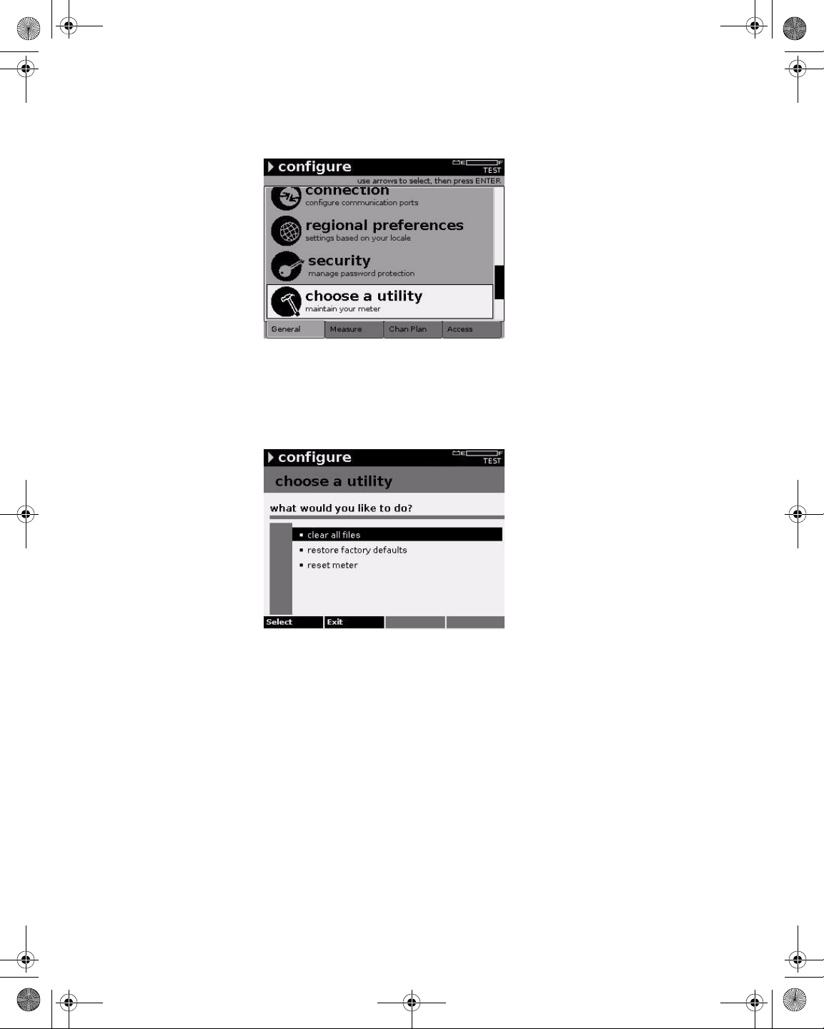
21128026 R001 DSAM Help User Guide.book Page 48 Thursday, February 5, 2009 2:02 PM
Chapter 5 Configuring the Meter
Configure – General Tab
Figure 35 Configure – General Tab: Choose a Utility
3 Using the arrow keys, select Choose a Utility.
4 Press ENTER.
Figure 36 Configure – Choose a Utility
5 Using the arrow keys, select the task you want to perform.
6 Press the Se lect softkey.
Clone
Sending Settings
48 DSAM Help User Guide Rev. 001
Use the Clone screen to copy configuration parameters, channel
plans, and limit plans between meters.
To send settings
1 Connect the meters via Ethernet cable.
The Ethernet port is located at the top of each meter. Use an
Ethernet crossover cable or a standard ethernet cable with a
crossover adapter to connect meters.
Page 89
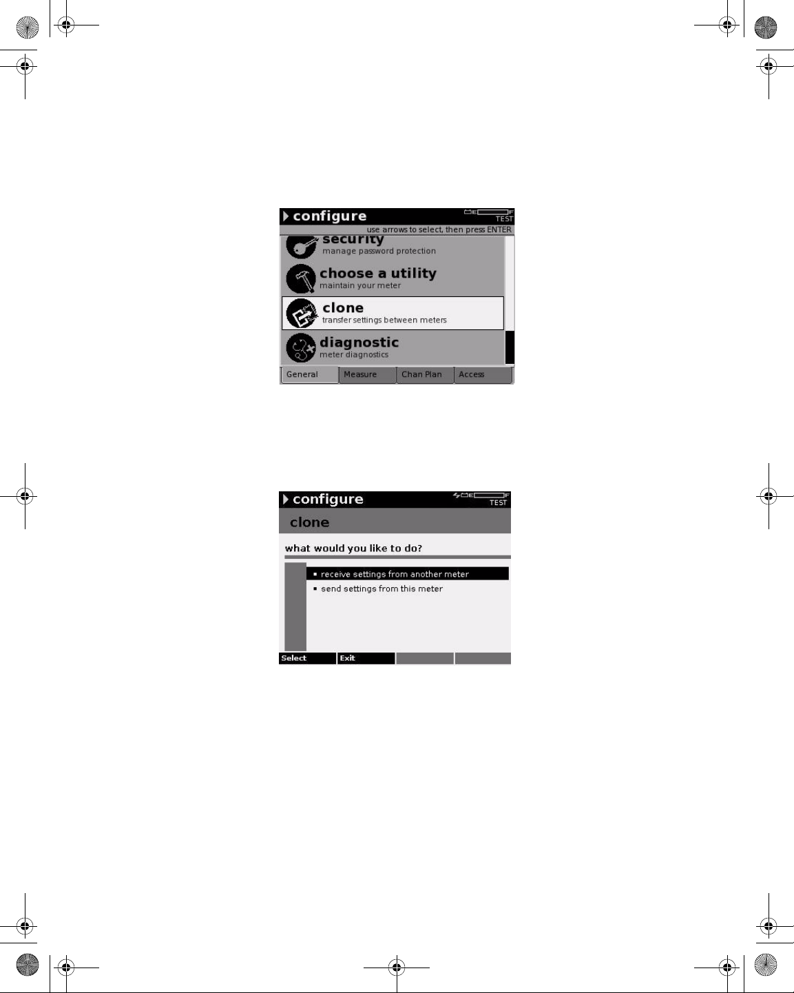
21128026 R001 DSAM Help User Guide.book Page 49 Thursday, February 5, 2009 2:02 PM
2 Press Configure.
3 Press the General softkey.
Figure 37 Configure – General Tab: Clone
Chapter 5 Configuring the Meter
Configure – General Tab
4 Using the arrow keys, select Clone.
5 Press ENTER.
Figure 38 Configure – Clone
6 Using the arrow keys, select Send settings from this meter.
7 Press the Select softkey.
8 Using the arrow keys and the Select softkey, select (or deselect)
the configuration group(s) you want to clone.
9 Press the OK softkey.
10 Press the Done softkey.
DSAM Help User Guide Rev. 001 49
Page 90

21128026 R001 DSAM Help User Guide.book Page 50 Thursday, February 5, 2009 2:02 PM
Chapter 5 Configuring the Meter
Configure – General Tab
11 Using the arrow keys, select receive settings from another
meter.
12 Press the Select softkey .
13 If cloning to multiple meters, attach the Ethernet cable to a
different meter and repeat.
Receiving Settings
Diagnostic
Testing the Keypad
To receive settings
1 Connect the meters via Ethernet cable.
The Ethernet port is located at the top of each meter. Use an
Ethernet crossover cable or a standard ethernet cable with a
crossover adapter to connect meters.
2 Press Configure.
3 Press the General softkey.
4 Using the arrow keys, select Clone.
5 Press ENTER.
6 Using the arrow keys, select receive settings from ano ther
meter.
Use the Diagnostic screen to test the keypad and/or connect to the
TPP network and control the DSAM from your computer.
To test the keypad
1 Press Configure.
2 Press the General softkey.
50 DSAM Help User Guide Rev. 001
Page 91
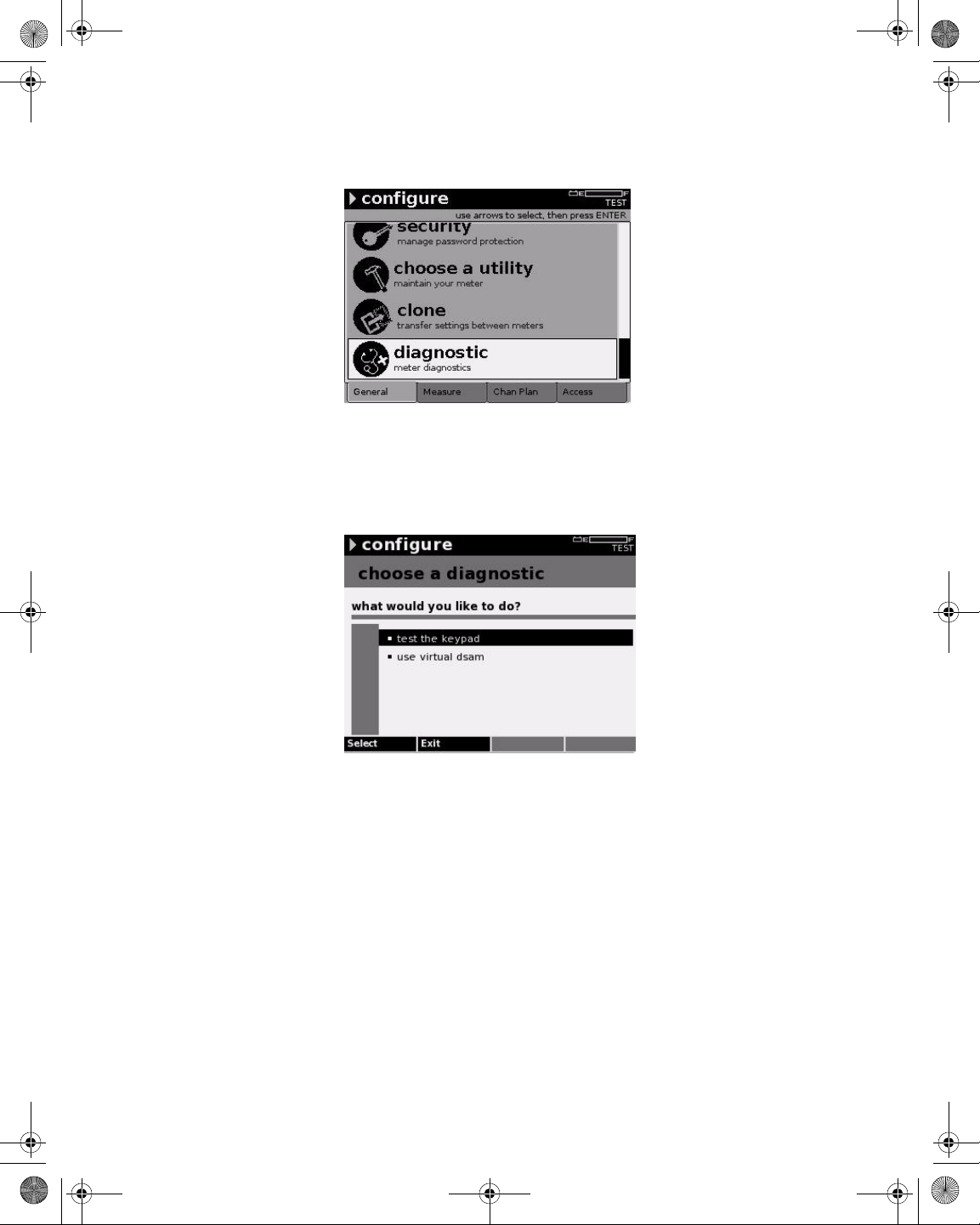
21128026 R001 DSAM Help User Guide.book Page 51 Thursday, February 5, 2009 2:02 PM
Figure 39 Configure – General Tab: Diagnostic
3 Using the arrow keys, select Diagnostic.
4 Press ENTER.
Chapter 5 Configuring the Meter
Configure – General Tab
Figure 40 Configure – Choose a Diagnostic
5 Using the arrow keys, select Test the Keypad.
6 Press ENTER.
An image of the keypad is displayed. When you press each key on
the pad, it is highlighted on the screen if functioning properly. The
key should remain highlighted as long as you press it.
DSAM Help User Guide Rev. 001 51
Page 92

21128026 R001 DSAM Help User Guide.book Page 52 Thursday, February 5, 2009 2:02 PM
Chapter 5 Configuring the Meter
Configure – General Tab
Figure 41 Configure – Keypad Test
7 If the keypad fails to function properly, contact your JDS
Uniphase Corporation Customer Service Representative.
8 Press the Done softkey.
Using Virtual DSAM
NOTE
During the test, the only keys that function normally are the Power
key and the Done softkey.
To use Virtual DSAM
1 Connect an Ethernet cable to the DSAM.
NOTE
In order to use Virtual DSAM, your computer and the Ethern et cable
must be connected to the same IP network or a public IP network.
2 Press Configure.
3 Press the General softkey.
4 Using the arrow keys, select Diagnostic.
5 Press ENTER.
6 Using the arrow keys, select Use Virtual DSAM.
7 Press the Se lect softkey.
52 DSAM Help User Guide Rev. 001
Page 93

21128026 R001 DSAM Help User Guide.book Page 53 Thursday, February 5, 2009 2:02 PM
The DSAM searches for an IP address. Once the meter o btains an
IP address, the Bind Results screen is displayed. The Bind
Results screen displays network assignments (IP address, Subnet
address, and Default Gateway) and meter information (CPE MAC
address).
Chapter 5 Configuring the Meter
Configure – General Tab
Figure 42 Configure – Bind Results
8 Launch the TPP Client application from your PC.
Figure 43 TPP – DSAM Remote Access
9 Click DSAM Remote Access.
The JDSU Remote DSAM window is displayed.
DSAM Help User Guide Rev. 001 53
Page 94

21128026 R001 DSAM Help User Guide.book Page 54 Thursday, February 5, 2009 2:02 PM
Chapter 5 Configuring the Meter
Configure – General Tab
Figure 44 TPP – JDSU Remote DSAM
10 From the Connection menu, select Connect to Meter.
The Connect to Meter window is displayed.
Figure 45 TPP – JDSU Remote DSAM
11 From the Bind Results screen (Figure 42), type the IP address.
12 Press the OK softkey.
54 DSAM Help User Guide Rev. 001
Page 95

21128026 R001 DSAM Help User Guide.book Page 55 Thursday, February 5, 2009 2:02 PM
Configure – Measure Tab
The Configure mode – Measure tab enables you to edit the following
configuration areas for the DSAM:
– Sweep Settings
–Limit Sets
– DOCSIS Throughput
– FDR Settings
– Other Settings
– Return QAM Generator
– Test Point Compensation
Chapter 5 Configuring the Meter
Configure – Measure Tab
Sweep Settings
Configuring Sweep
Settings
The Sweep Settings screen enables you to set the sweep, tilt, limit,
and reverse sweep port parameters.
To configure sweep settings
1 Press Configure.
2 Press the Measure softkey.
Figure 46 Configure – Measure Tab: Sweep Settings
3 Using the arrow keys, select Sweep Settings.
4 Press ENTER.
DSAM Help User Guide Rev. 001 55
Page 96
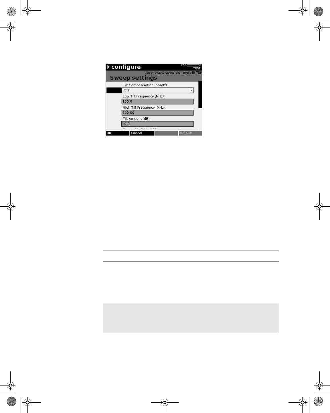
21128026 R001 DSAM Help User Guide.book Page 56 Thursday, February 5, 2009 2:02 PM
Chapter 5 Configuring the Meter
Configure – Measure Tab
Figure 47 Configure – Sweep Settings
5 Using the arrow keys, select the parameter you want to edit.
6 Press ENTER.
7 Using the arrow keys and the alphanumeric keypad, edit the
value.
OR
8 Using the arrow keys, select an option.
9 Press ENTER.
10 Press the OK softkey.
Table 21 Sweep Settings Parameters
Name Description
Tilt Compensation
Low Tilt Frequency
Sweep Tilt Compensation is different from the standard DSAM Tilt mode. Typically, Tilt Compensation
is used to adjust the sweep response on a branch
of a network where the branch tilt is not the same as
the mainline network. Valid options are On and Off.
The default option is Off.
Use the up and down arrow keys to increase or
decrease the value in 10 kHz increments. The valid
range is 5.0 to 999.99 MHz. The default value is 5.0
MHz.
56 DSAM Help User Guide Rev. 001
Page 97
21128026 R001 DSAM Help User Guide.book Page 57 Thursday, February 5, 2009 2:02 PM
Table 21 Sweep Settings Parameters (Continued)
Name Description
Chapter 5 Configuring the Meter
Configure – Measure Tab
High Tilt Fr equency
Use the up and down arrows to increase or
decrease the value in 10 kHz increments. The valid
range is 6.00 to 1,000.00 MHz. The default value is
1,000.00 MHz.
Tilt Amount The tilt adjustment required (positive or negative),
that adds to or subtracts from the mainline network
tilt represented in the sweep reference file (which is
typically captured at the output of the node amp).
Use the up and down arrows to increase or
decrease the value in .01 dB increments. The valid
range is -50.0 to +50.0 dB. The default value is 0.0
dB.
Sweep Limit Valid options are On and Off. The default option is
Off.
Sweep Limit
Value
The greatest deviation allowed for a passing sweep
response. The measured deviation is referred to as
the sweep max-min value or sweep peak-to-valley
value, both in dB delta. Thus, a Sweep Limit Value
of 2.0 dB allows a sweep max-min value in the
DSAM sweep display no greater than +1.0 to -1.0
dB on either side of the ideal sweep response. The
valid range is 0.00 to 5.0 dB. The default value is
2.00 dB.
Reverse Sweep
Port
Valid options are Port 1 - Bidirectional and Port 2 Reverse Only. If you select Port 2, both ports are
functional for connecting to directional test points.
Port 1 handles the downstream or forward traffic
while Port 2 handles upstream or reverse traffic.
Two-way test modes other than sweep may use this
configuration as well, such as DOCSIS and VoIP
testing on directional test points. The default option
is Port 2 - Reverse Only.
NOTE:
– If Port 1 is selected, both upstream and down-
stream traffic is handled through Port 1.
– Reverse Sweep Port only applies to DSAM
6000 models.
DSAM Help User Guide Rev. 001 57
Page 98
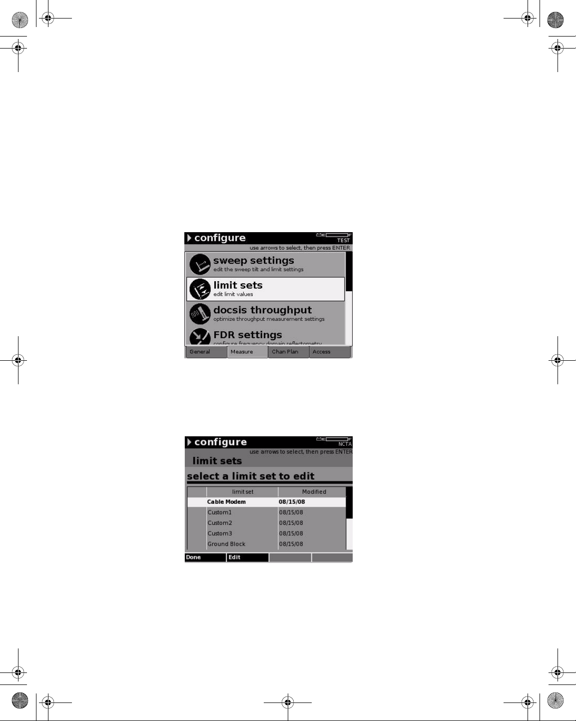
21128026 R001 DSAM Help User Guide.book Page 58 Thursday, February 5, 2009 2:02 PM
Chapter 5 Configuring the Meter
Configure – Measure Tab
Limit Sets
Configuring Limit
Sets
Use Limit Sets to configure the limit sets for measurements for tap,
ground block, TV, cable modem, proof, and up to three custom limits.
The limit set parameters you define remain constant for all channel
plans and measurement modes.
To configure limit sets
1 Press Configure.
2 Press the Measure softkey.
Figure 48 Configure – Measure Tab: Limit Sets
3 Using the arrow keys, select Limit Sets.
4 Press ENTER.
Figure 49 Configure – Limit Sets
5 Using the arrow keys, select the limit set you want to edit.
6 Press the Edit softkey.
58 DSAM Help User Guide Rev. 001
Page 99
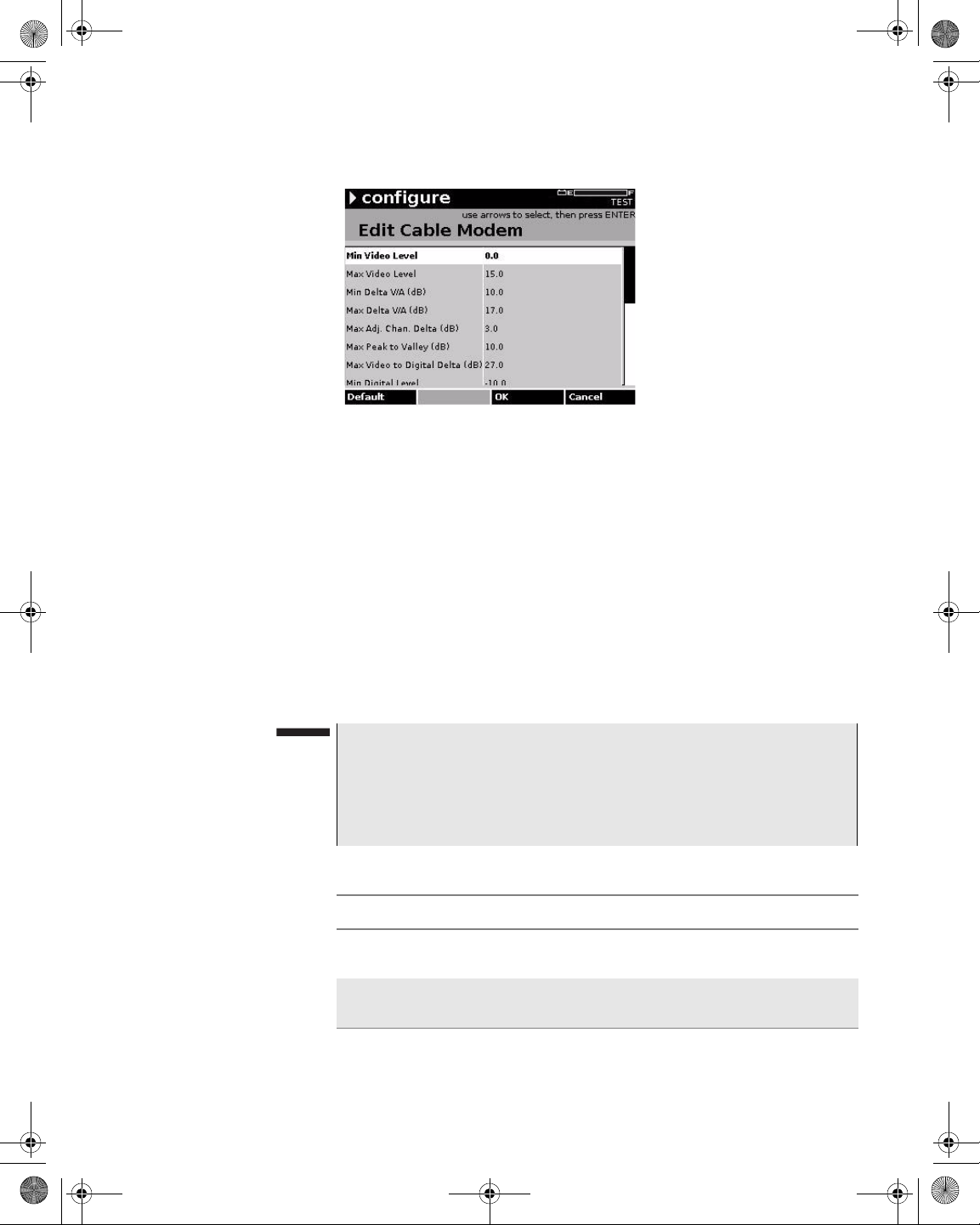
21128026 R001 DSAM Help User Guide.book Page 59 Thursday, February 5, 2009 2:02 PM
Figure 50 Configure – Edit Cable Modem
7 Using the arrow keys, select the parameter you want to edit.
8 Press ENTER.
Chapter 5 Configuring the Meter
Configure – Measure Tab
9 Using the arrow keys and the alphanumeric keypad, edit the
value.
10 Press ENTER.
11 Press ENTER.
12 Press the OK softkey.
13 Press the Done softkey.
NOTE
If a “key” icon is displayed to the left of a limit set, it indicates that
the limit set is locked and requires a PIN entry prior to editing.
To reset the currently selected parameter to it s factory default value,
press the Default softkey.
Table 22 Limit Set Parameters
Name Description
Min Video Level The minimum video signal level before it exceeds
your set limit. The default value is 0.0.
Max Video Level The maximum video signal level before it exceeds
your set limit. The default value is 15.0.
DSAM Help User Guide Rev. 001 59
Page 100
21128026 R001 DSAM Help User Guide.book Page 60 Thursday, February 5, 2009 2:02 PM
Chapter 5 Configuring the Meter
Configure – Measure Tab
Table 22 Limit Set Parameters (Continued)
Name Description
Min Delta V/A
(dB)
Max Delta V/A
(dB)
Max Adj. Chan.
Delta (dB)
Max Peak to Valley (dB)
The minimum delta video to audio before it exceeds
your set limit. Delta V/A is calculated by subtracting
the audio carrier level (first if DUAL) from the video
carrier level (for analog TV and DUAL type channels only). The valid range is 0.0 to 17.0. The
default value is 10.0.
The maximum delta video to audio before it
exceeds your set limit. Delta V/A is calculated by
subtracting the audio carrier level (first if DUAL)
from the video carrier level (for analog TV and
DUAL type channels only). The valid range is 0.0 to
100.0. The default value is 17.0.
(An adjacent channel is the next channel up to 9
MHz in front of the current channel. This limit check
is only applicable in AutoTests.) The maximum
adjacent channel delta before it exceeds your set
limit. The valid range is 0.0 to 100.0. The default
value is 3.0.
(The peak-to-valley is the highest level in the channel plan less the lowest level in the channel plan
or, the delta between the highest and lowest levels
in the channel plan.) The maximum peak to valley
before it exceeds your set limit. The valid range is
0.0 to 100.0. The default value is 10.0.
Max Video to Digital Delta (dB)
The maximum video to digital delta before it
exceeds your set limit. The valid range is 0.0 to
100.0. The default value is 27.0.
Min Digital Level The minimum digital level (in decibels) before it
exceeds your set limit. The valid range is -40.0 to
60.0. The default value is -15.0.
Max Digital Level The maximum digital level before it exceeds your
set limit. The valid range is -40.0 to 60.0. The
default value is 10.0.
Signal Quality 64
QAM
The minimum signal quality at 64 QAM. before it
falls below your set limit. The default value is 28.0
dB if digital the performance unit is set to MER in
Regional Preferences. The default value is 2.61 if
the digital performance unit is set to EVM in
Regional Preferences.
60 DSAM Help User Guide Rev. 001
 Loading...