

Page 1

2100/4100 OTDR Modules
OTDR Modules for T-BERD/MTS-2000 and T-BERD/MTS-4000
Handheld Modular Test Set
User Manual
Page 2

Page 3

2100/4100 OTDR Modules
OTDR Modules for T-BERD/MTS-2000 and T-BERD/MTS-4000
Handheld Modular Test Set
User Manual
Page 4

Page 5

Notice
Every effort was made to ensure that the information in this document
was accurate at the time of printing. However, information is subject to
change without notice, and JDSU reserves the right to provide an
addendum to this document with information not available at the time th at
this document was created.
Copyright
Trademarks
Ordering
information
WEEE Directive
Compliance
© Copyright 2013 JDSU, LLC. All rights reserved. JDSU, Enabling
Broadband and Optical Innovation, and its logo a re trademarks of JDSU,
LLC. All other trademarks and registered tradema rks are the property of
their respective owners. No part of this guide may be reproduced or
transmitted electronically or otherwise without written permission of the
publisher.
JDSU and MTS/T-BERD 2000/4000 are trademarks or registered trademarks of JDSU in the United States and/or other countries.
Microsoft, Windows, Windows CE, Windows NT, and Microsoft Internet
Explorer are either trademarks or registered trademarks of Microsoft
Corporation in the United States and/or other countries.
Netscape Navigator is a trademark or registered trademark of Net scape
Communications Corporation in the United States and other countries.
This guide is a product of JDSU's Technical Information Development
Department, issued as part of the User Manual.
JDSU has established processes in compliance with the W aste Electrical
and Electronic Equipment (WEEE) Directive, 2002/96/EC.
This product should not be disposed of as unsorted municipal wast e and
should be collected separately and disposed of according to your
national regulations. In the European Union, all equipment purchased
from JDSU after 2005-08-13 can be returned for disposal at the end of
its useful life. JDSU will ensure that all waste equipment returned is
reused, recycled, or disposed of in an environmentally friendly manner,
and in compliance with all applicable national and int ernational waste
legislation.
It is the responsibility of the equipme nt owner to return the equipme nt to
JDSU for appropriate disposal. If the equipment was imported by a
reseller whose name or logo is marked on the equipment, then th e owner
should return the equipment directly to the reseller.
User Manual 770000102/08 v
Page 6

Instructions for returning waste equipment to JDSU can be found in the
Environmental section of JDSU’s web site at www.jdsu.com. If you have
questions concerning disposal of your equipment, contact JDSU’s
WEEE Program Management team at WEEE.EMEA@jdsu.com.
vi User Manual 770000102/08
Page 7

Table of Contents
About This Guide xv
Purpose and scope . . . . . . . . . . . . . . . . . . . . . . . . . . . . . . . . . . xvi
Assumptions . . . . . . . . . . . . . . . . . . . . . . . . . . . . . . . . . . . . . . . . . xvi
Technical assistance . . . . . . . . . . . . . . . . . . . . . . . . . . . . . . . . . . . xvi
Recycling Information . . . . . . . . . . . . . . . . . . . . . . . . . . . . . . . . . .xvii
Conventions . . . . . . . . . . . . . . . . . . . . . . . . . . . . . . . . . . . . . . . . . .xvii
Chapter 1 Principle of Measurement 1
Principle of reflectometry measurements . . . . . . . . . . . . . . . . . 2
Information yielded by the measurement . . . . . . . . . . . . . . . . . . . . . . . . . . .2
Validity of Measurement . . . . . . . . . . . . . . . . . . . . . . . . . . . . . . . . . . . . . . . .3
Reflectance . . . . . . . . . . . . . . . . . . . . . . . . . . . . . . . . . . . . . . . . . . . . . . . . . . 3
Principle of optical power and attenuation measurements . . . . . .4
Power measureme nts . . . . . . . . . . . . . . . . . . . . . . . . . . . . . . . . . . . . . . . . . .4
Attenuation measurements (optical link loss) . . . . . . . . . . . . . . . . . . . . . . . . 4
Chapter 2 Starting up 7
Unpacking the device - Precautions . . . . . . . . . . . . . . . . . . . . . . 8
Fitting and removing a module . . . . . . . . . . . . . . . . . . . . . . . . . . . . .8
User Manual 770000102/08 vii
Page 8

Table of Contents
Fitting a module . . . . . . . . . . . . . . . . . . . . . . . . . . . . . . . . . . . . . . . . . . . . . . 8
Removing a module . . . . . . . . . . . . . . . . . . . . . . . . . . . . . . . . . . . . . . . . . . 10
Universal connectors and adapters . . . . . . . . . . . . . . . . . . . . . . . .10
Adapter types . . . . . . . . . . . . . . . . . . . . . . . . . . . . . . . . . . . . . . . . . . . . . . . 10
Switching adapter type . . . . . . . . . . . . . . . . . . . . . . . . . . . . . . . . . . . . . . . . 10
Changing the adapter on a LA OTDR Module . . . . . . . . . . . . . . . . . . . . . . 11
Cleaning universal connectors . . . . . . . . . . . . . . . . . . . . . . . . . . . . . . . . . . 12
Chapter 3 Activating OTDR function 13
Selecting the SmartOTDR™ . . . . . . . . . . . . . . . . . . . . . . . . . . . 14
Principle of the SmartOTDR™ . . . . . . . . . . . . . . . . . . . . . . . . . . . . . . . . . . 14
Selecting SmartO TDR™ . . . . . . . . . . . . . . . . . . . . . . . . . . . . . . . . . . . . . . . 14
Selecting the OTDR Expert function . . . . . . . . . . . . . . . . . . . . . . .15
Principle of the OTDR Expert . . . . . . . . . . . . . . . . . . . . . . . . . . . . . . . . . . . 15
Selecting OTDR Expert . . . . . . . . . . . . . . . . . . . . . . . . . . . . . . . . . . . . . . . 15
Chapter 4 Configuring the reflectometry test 17
Configuring the unit for SmartOTDR™ . . . . . . . . . . . . . . . . . . 18
Selecting the configu ration file . . . . . . . . . . . . . . . . . . . . . . . . . . . . . . . . . . 18
Modifying some parameters before the acquisition . . . . . . . . . . . . . . . . . . 19
Configuring the test in OTDR Expert . . . . . . . . . . . . . . . . . . . . . . .20
Configuring the Acq u is i tio n parameters . . . . . . . . . . . . . . . . . . . . . . . . . . . 21
Parameters . . . . . . . . . . . . . . . . . . . . . . . . . . . . . . . . . . . . . . . . . . 21
Launch cable pa rameters . . . . . . . . . . . . . . . . . . . . . . . . . . . . . . . .23
Configuring the Alarms parameters . . . . . . . . . . . . . . . . . . . . . . . . . . . . . . 24
Configuring the Mea s u r e ment parameters . . . . . . . . . . . . . . . . . . . . . . . . . 25
Measurement parameters . . . . . . . . . . . . . . . . . . . . . . . . . . . . . . . 25
Detection parameters . . . . . . . . . . . . . . . . . . . . . . . . . . . . . . . . . . . 27
Configuring the Link parameters . . . . . . . . . . . . . . . . . . . . . . . . . . . . . . . . . 29
Configuring the file storage parameters . . . . . . . . . . . . . . . . . . . . . . . . . . . 30
Configuration in Test Auto mode . . . . . . . . . . . . . . . . . . . . . . . . . . . . . . . . 32
Saving configuratio n parameters in a file . . . . . . . . . . . . . . . . . . . . . . . . . . 33
Loading an existing configuration file in ExpertOTDR . . . . . . . . . . . . . . . . 34
User Manual 770000102/08 viii
Page 9

Table of Contents
Chapter 5 Launching a reflectometry test and displaying results 37
Performing OTDR acquisitions . . . . . . . . . . . . . . . . . . . . . . . . . 38
Performing an acquisit io n in R e al Time mode . . . . . . . . . . . . . . . . . . . . . . 38
Principle of the Real time mode . . . . . . . . . . . . . . . . . . . . . . . . . . .38
Performing acquisition in Real Time . . . . . . . . . . . . . . . . . . . . . . . . 38
Stopping the real time acquisition . . . . . . . . . . . . . . . . . . . . . . . . . . 39
Performing a measure ment with SmartOTDR™ . . . . . . . . . . . . . . . . . . . . 40
Performing an acquisit io n wit h O TDR Expert . . . . . . . . . . . . . . . . . . . . . . . 40
Performing an acquisition from Results page . . . . . . . . . . . . . . . . . . . . . . . 42
Multi-wavelength acquisition . . . . . . . . . . . . . . . . . . . . . . . . . . . . . . . . . . . . 43
Actions on trace du rin g a c q uisition . . . . . . . . . . . . . . . . . . . . . . . . . . . . . . . 43
Results display . . . . . . . . . . . . . . . . . . . . . . . . . . . . . . . . . . . . . . . .45
Common function s . . . . . . . . . . . . . . . . . . . . . . . . . . . . . . . . . . . . . . . . . . . 46
Display of events on the trace . . . . . . . . . . . . . . . . . . . . . . . . . . . . . 46
Results table . . . . . . . . . . . . . . . . . . . . . . . . . . . . . . . . . . . . . . . . . . 47
Cursors . . . . . . . . . . . . . . . . . . . . . . . . . . . . . . . . . . . . . . . . . . . . . 49
Zoom function . . . . . . . . . . . . . . . . . . . . . . . . . . . . . . . . . . . . . . . . 50
Shift function (OTDR Expert only) . . . . . . . . . . . . . . . . . . . . . . . . . . 51
Summary . . . . . . . . . . . . . . . . . . . . . . . . . . . . . . . . . . . . . . . . . . . .52
Display of traces in overlay . . . . . . . . . . . . . . . . . . . . . . . . . . . . . . . 53
Traces display in double acquisition mode . . . . . . . . . . . . . . . . . . .54
Advanced functions in OTDR Expert mode . . . . . . . . . . . . . . . . . .54
Automatic measurement and detection . . . . . . . . . . . . . . . . . . . . . . . . . . . 55
Addition of event s . . . . . . . . . . . . . . . . . . . . . . . . . . . . . . . . . . . . . . . . . . . . 55
Manual measurements . . . . . . . . . . . . . . . . . . . . . . . . . . . . . . . . . . . . . . . . 56
Measurements of slope . . . . . . . . . . . . . . . . . . . . . . . . . . . . . . . . . 56
Measurement of ORL . . . . . . . . . . . . . . . . . . . . . . . . . . . . . . . . . . . 58
Measurement of Reflectance . . . . . . . . . . . . . . . . . . . . . . . . . . . . . 58
Splice measurements . . . . . . . . . . . . . . . . . . . . . . . . . . . . . . . . . . .59
Memorization of the po sit io n o f e vents . . . . . . . . . . . . . . . . . . . . . . . . . . . . 60
Overlay trace func t io n . . . . . . . . . . . . . . . . . . . . . . . . . . . . . . . . . . . . . . . . . 61
Overlaying several traces stored in memory . . . . . . . . . . . . . . . . . . 62
Display of traces in overlay . . . . . . . . . . . . . . . . . . . . . . . . . . . . . . . 62
Adding traces in overlay . . . . . . . . . . . . . . . . . . . . . . . . . . . . . . . . . 62
Swapping overlay traces . . . . . . . . . . . . . . . . . . . . . . . . . . . . . . . . 62
Removing a trace . . . . . . . . . . . . . . . . . . . . . . . . . . . . . . . . . . . . . . 63
Quitting the overlay menu . . . . . . . . . . . . . . . . . . . . . . . . . . . . . . . . 63
Reference Trace function . . . . . . . . . . . . . . . . . . . . . . . . . . . . . . . . . . . . . . 63
Use of the reference trace function in the Result page . . . . . . . . . .63
Using the refe rence trace function in the explorer . . . . . . . . . . . . . . 64
SLM (Smart Link Mapper) option . . . . . . . . . . . . . . . . . . . . . . . . . .65
Show the detailed information of one event . . . . . . . . . . . . . . . . . . . . . . . . 66
User Manual 770000102/08 ix
Page 10

Table of Contents
Event View . . . . . . . . . . . . . . . . . . . . . . . . . . . . . . . . . . . . . . . . . . . . . . . . . 66
Changing the type of an event . . . . . . . . . . . . . . . . . . . . . . . . . . . .67
OptiPulses option . . . . . . . . . . . . . . . . . . . . . . . . . . . . . . . . . . . . . .68
Configuring the OTDR acquisition with OptiPulses mode . . . . . . . . . . . . . 68
Results in OptiPulses mode . . . . . . . . . . . . . . . . . . . . . . . . . . . . . . . . . . . . 69
Saving the trace(s) and generating a report . . . . . . . . . . . . . . . . .70
Saving results and creating a report from results page . . . . . . . . . . . . . . . 70
Opening a report . . . . . . . . . . . . . . . . . . . . . . . . . . . . . . . . . . . . . . . . . . . . . 72
Storing OTDR measurements . . . . . . . . . . . . . . . . . . . . . . . . . . . . .73
Recalling OTDR files . . . . . . . . . . . . . . . . . . . . . . . . . . . . . . . . . . . . . . . . . 73
Chapter 6 FTTA-SLM Software option 75
Principle of FTTA-SLM . . . . . . . . . . . . . . . . . . . . . . . . . . . . . . . . 76
Acceptance Test in g . . . . . . . . . . . . . . . . . . . . . . . . . . . . . . . . . . . . . . . . . . 76
Troubleshooting Testing . . . . . . . . . . . . . . . . . . . . . . . . . . . . . . . . . . . . . . . 77
Configuring the Reflectometry test for FTTA network . . . . . . . . .78
FTTA setup . . . . . . . . . . . . . . . . . . . . . . . . . . . . . . . . . . . . . . . . . . . . . . . . . 79
Alarms paramet e r s . . . . . . . . . . . . . . . . . . . . . . . . . . . . . . . . . . . . . . . . . . . 80
File parameters . . . . . . . . . . . . . . . . . . . . . . . . . . . . . . . . . . . . . . . . . . . . . . 81
Launching the acquisition . . . . . . . . . . . . . . . . . . . . . . . . . . . . . . .83
Results page . . . . . . . . . . . . . . . . . . . . . . . . . . . . . . . . . . . . . . . . . .84
Trace View . . . . . . . . . . . . . . . . . . . . . . . . . . . . . . . . . . . . . . . . . . . . . . . . . 84
SmartLink view . . . . . . . . . . . . . . . . . . . . . . . . . . . . . . . . . . . . . . . . . . . . . . 85
Displaying the details of an event . . . . . . . . . . . . . . . . . . . . . . . . . . 85
Event View . . . . . . . . . . . . . . . . . . . . . . . . . . . . . . . . . . . . . . . . . . . 86
Changing the name of an event . . . . . . . . . . . . . . . . . . . . . . . . . . . 87
Saving the trace(s) and generating a report . . . . . . . . . . . . . . . . .87
Saving results and creating a report from results page . . . . . . . . . . . . . . . 88
Opening a report . . . . . . . . . . . . . . . . . . . . . . . . . . . . . . . . . . . . . . . . . . . . . 89
Chapter 7 Power meter and Source options of the OTDR Modules 91
Connection to the power meter . . . . . . . . . . . . . . . . . . . . . . . . 92
Configuring the Power meter . . . . . . . . . . . . . . . . . . . . . . . . . . . . .92
Configuring the measurement parameters of the power meter . . . . . . . . . 93
Configuring the alarm parameters of the power meter . . . . . . . . . . . . . . . . 94
Activating the Source function . . . . . . . . . . . . . . . . . . . . . . . . . . . .94
User Manual 770000102/08 x
Page 11

Table of Contents
Result page . . . . . . . . . . . . . . . . . . . . . . . . . . . . . . . . . . . . . . . . . . .95
Result page of the Power meter . . . . . . . . . . . . . . . . . . . . . . . . . . . . . . . . . 95
Table of results . . . . . . . . . . . . . . . . . . . . . . . . . . . . . . . . . . . . . . . . 95
Commands of the power meter parameters . . . . . . . . . . . . . . . . . .96
Result page of the Source . . . . . . . . . . . . . . . . . . . . . . . . . . . . . . . . . . . . . 96
Performing the power level measurement . . . . . . . . . . . . . . . . . .97
Performing the insertion loss measurement . . . . . . . . . . . . . . . . .98
Setting the zero value o f th e p o wer meter . . . . . . . . . . . . . . . . . . . . . . . . . 98
Carrying out the reference . . . . . . . . . . . . . . . . . . . . . . . . . . . . . . . . . . . . . 98
Carrying out the side by side reference . . . . . . . . . . . . . . . . . . . . . . 99
Carrying out the reference in loopback mode . . . . . . . . . . . . . . . . 100
Measurements on the fiber under test . . . . . . . . . . . . . . . . . . . . . . . . . . . 101
Storing and reloading results . . . . . . . . . . . . . . . . . . . . . . . . . . . .102
File Setup . . . . . . . . . . . . . . . . . . . . . . . . . . . . . . . . . . . . . . . . . . . . . . . . . 102
Storing results . . . . . . . . . . . . . . . . . . . . . . . . . . . . . . . . . . . . . . . . . . . . . . 102
Loading results . . . . . . . . . . . . . . . . . . . . . . . . . . . . . . . . . . . . . . . . . . . . . 102
Chapter 8 FiberComplete Modules 103
General introduction . . . . . . . . . . . . . . . . . . . . . . . . . . . . . . . . 104
Principle . . . . . . . . . . . . . . . . . . . . . . . . . . . . . . . . . . . . . . . . . . . . . . . . . . 104
Configurations . . . . . . . . . . . . . . . . . . . . . . . . . . . . . . . . . . . . . . . . . . . . . . 105
Activating the function . . . . . . . . . . . . . . . . . . . . . . . . . . . . . . . . .107
Establishing References . . . . . . . . . . . . . . . . . . . . . . . . . . . . . . . .107
Reference stage process . . . . . . . . . . . . . . . . . . . . . . . . . . . . . . . . . . . . . 108
Loopback Referencing method . . . . . . . . . . . . . . . . . . . . . . . . . . .109
Side-by-Side referencing method . . . . . . . . . . . . . . . . . . . . . . . . . 110
Configuring the units . . . . . . . . . . . . . . . . . . . . . . . . . . . . . . . . . . 111
Configuring the acquisition . . . . . . . . . . . . . . . . . . . . . . . . . . . . . . . . . . . . 111
Configuring the file saving for FiberComplete results . . . . . . . . . . . . . . . . 115
Saving the parameters from FiberComplete configuration . . . . . . . . . . . . 116
Loading a configuration file FiberComplete . . . . . . . . . . . . . . . . . . . . . . . 116
Performing the tests . . . . . . . . . . . . . . . . . . . . . . . . . . . . . . . . . . .117
Sending a message to the distant Platform . . . . . . . . . . . . . . . . . . . . . . . 117
Starting the test . . . . . . . . . . . . . . . . . . . . . . . . . . . . . . . . . . . . . . . . . . . . . 118
Results screen . . . . . . . . . . . . . . . . . . . . . . . . . . . . . . . . . . . . . . . .119
Cable view . . . . . . . . . . . . . . . . . . . . . . . . . . . . . . . . . . . . . . . . . . . . . . . . 119
Fiber View . . . . . . . . . . . . . . . . . . . . . . . . . . . . . . . . . . . . . . . . . . . . . . . . . 120
Fault Finder . . . . . . . . . . . . . . . . . . . . . . . . . . . . . . . . . . . . . . . . . . . . . . . . 120
User Manual 770000102/08 xi
Page 12

Table of Contents
OTDR . . . . . . . . . . . . . . . . . . . . . . . . . . . . . . . . . . . . . . . . . . . . . . . . . . . . 121
Saving results and generating a report . . . . . . . . . . . . . . . . . . . .122
Saving results and creating a report from results page . . . . . . . . . . . . . . 122
Opening a report . . . . . . . . . . . . . . . . . . . . . . . . . . . . . . . . . . . . . . . . . . . . 123
File management . . . . . . . . . . . . . . . . . . . . . . . . . . . . . . . . . . . . . .124
Storing results . . . . . . . . . . . . . . . . . . . . . . . . . . . . . . . . . . . . . . . . . . . . . . 124
Filenaming convention . . . . . . . . . . . . . . . . . . . . . . . . . . . . . . . . . . . . . . . 124
Chapter 9 File management 127
File Setup menu . . . . . . . . . . . . . . . . . . . . . . . . . . . . . . . . . . . . 128
Managing tabs . . . . . . . . . . . . . . . . . . . . . . . . . . . . . . . . . . . . . . . . . . . . . 128
File signature . . . . . . . . . . . . . . . . . . . . . . . . . . . . . . . . . . . . . . . . . . . . . . 129
File configuration . . . . . . . . . . . . . . . . . . . . . . . . . . . . . . . . . . . . . . . . . . . 129
Dir . . . . . . . . . . . . . . . . . . . . . . . . . . . . . . . . . . . . . . . . . . . . . . . .129
Rules for naming files (Filenaming parameter) . . . . . . . . . . . . . . . 130
Name of a file . . . . . . . . . . . . . . . . . . . . . . . . . . . . . . . . . . . . . . . . 131
Save mode . . . . . . . . . . . . . . . . . . . . . . . . . . . . . . . . . . . . . . . . . . 131
Auto store . . . . . . . . . . . . . . . . . . . . . . . . . . . . . . . . . . . . . . . . . . .132
Change Fiber Nbr . . . . . . . . . . . . . . . . . . . . . . . . . . . . . . . . . . . . .132
Fiber/Link Descrip tio n . . . . . . . . . . . . . . . . . . . . . . . . . . . . . . . . . . . . . . . . 132
Fiber ID and Fiber Number . . . . . . . . . . . . . . . . . . . . . . . . . . . . . . 132
Cable Id . . . . . . . . . . . . . . . . . . . . . . . . . . . . . . . . . . . . . . . . . . . . 132
Direction . . . . . . . . . . . . . . . . . . . . . . . . . . . . . . . . . . . . . . . . . . . . 132
Location A . . . . . . . . . . . . . . . . . . . . . . . . . . . . . . . . . . . . . . . . . . 133
Location B . . . . . . . . . . . . . . . . . . . . . . . . . . . . . . . . . . . . . . . . . . 133
Operator . . . . . . . . . . . . . . . . . . . . . . . . . . . . . . . . . . . . . . . . . . . . 133
Comment . . . . . . . . . . . . . . . . . . . . . . . . . . . . . . . . . . . . . . . . . . . 133
File export (T-BERD/MTS 4000 only) . . . . . . . . . . . . . . . . . . . . . . . . . . . . 133
Buttons on the right of the screen . . . . . . . . . . . . . . . . . . . . . . . . . . . . . . . 133
Explorer Function . . . . . . . . . . . . . . . . . . . . . . . . . . . . . . . . . . . . .134
Description of the explorer . . . . . . . . . . . . . . . . . . . . . . . . . . . . . . . . . . . . 134
Storage media . . . . . . . . . . . . . . . . . . . . . . . . . . . . . . . . . . . . . . . . . . . . . 135
Storage media built into the Platform . . . . . . . . . . . . . . . . . . . . . .135
External USB storage media . . . . . . . . . . . . . . . . . . . . . . . . . . . . 135
Remote T-BERD/MTS and data transfer . . . . . . . . . . . . . . . . . . . .136
Abbreviations for storage media . . . . . . . . . . . . . . . . . . . . . . . . . . . . . . . . 136
Directories and files edit function . . . . . . . . . . . . . . . . . . . . . . . . . . . . . . . 136
Saving files from the Explorer . . . . . . . . . . . . . . . . . . . . . . . . . . . . . . . . . . 136
User Manual 770000102/08 xii
Page 13

Table of Contents
Loading files and displaying traces . . . . . . . . . . . . . . . . . . . . . . . . . . . . . . 137
Simple loading . . . . . . . . . . . . . . . . . . . . . . . . . . . . . . . . . . . . . . . 137
Loading several traces in overlay . . . . . . . . . . . . . . . . . . . . . . . . .137
Load with configuration . . . . . . . . . . . . . . . . . . . . . . . . . . . . . . . . .138
Exporting files . . . . . . . . . . . . . . . . . . . . . . . . . . . . . . . . . . . . . . . . . . . . . . 138
Explorer/Link Manager . . . . . . . . . . . . . . . . . . . . . . . . . . . . . . . . . 138
Editing function . . . . . . . . . . . . . . . . . . . . . . . . . . . . . . . . . . . . . . . 139
Exporting a directory in a txt file . . . . . . . . . . . . . . . . . . . . . . . . . . . 139
Generating pdf report(s) . . . . . . . . . . . . . . . . . . . . . . . . . . . . . . . .140
Using the Merge key, with the txt/pdf files . . . . . . . . . . . . . . . . . . .141
Sending files by e-mail (T-BERD/MTS 4000 only) . . . . . . . . . . . . . 142
Chapter 10 Technical specifications 143
OTDR modules . . . . . . . . . . . . . . . . . . . . . . . . . . . . . . . . . . . . . 144
Characteristics of refle c to metry measurements . . . . . . . . . . . . . . . . . . . . 144
Manual Measurement . . . . . . . . . . . . . . . . . . . . . . . . . . . . . . . . .145
Typical specificatio n s . . . . . . . . . . . . . . . . . . . . . . . . . . . . . . . . . . . . . . . . 145
Ranges . . . . . . . . . . . . . . . . . . . . . . . . . . . . . . . . . . . . . . . . . . . . . . . . . . . 147
Class of the lasers of the OTDR modules . . . . . . . . . . . . . . . . . . . . . . . . 148
OTDR modules measurement . . . . . . . . . . . . . . . . . . . . . . . . . . . . . . . . . 148
Technical specifications of the Power meter function on module . .
148
Technical specifications of the Source function on module . . .149
Technical specifications of the FiberComplete modules . . . . . .150
Chapter 11 Options and accessories 151
References of measurement modules . . . . . . . . . . . . . . . . . . 152
OTDR Modules . . . . . . . . . . . . . . . . . . . . . . . . . . . . . . . . . . . . . . . . . . . . . 152
FiberComplete module with OTDR function . . . . . . . . . . . . . . . . . . . . . . . 153
FiberComplete module with Fault Finder function . . . . . . . . . . . . . . . . . . 153
Options . . . . . . . . . . . . . . . . . . . . . . . . . . . . . . . . . . . . . . . . . . . . . . . . . . . 153
User manual references . . . . . . . . . . . . . . . . . . . . . . . . . . . . . . . .154
References of optical connectors and adapters . . . . . . . . . . . . .154
Index 157
User Manual 770000102/08 xiii
Page 14

Table of Contents
xiv User Manual 770000102/08
Page 15

About This Guide
The T-BERD/MTS-2000/4000 of JDSU provides a handheld, modular
platform designed for the construction, validation and maintenance of
fiber networks.
The topics discussed in this chapter are as follows:
– “Purpose and scope” on page xvi
– “Assumptions” on page xvi
– “Technical assistance” on pagexvi
– “Technical assistance” on pagexvi
– “Conventions” on page xvii
User Manual 770000102/08 xv
Page 16

About This Guide
Purpose and scope
Purpose and scope
The purpose of this guide is to help you successfully use the T-BERD/
MTS-2000/4000 features and capabilities. This guide includes taskbased instructions that describe how to install, configure, use, and troubleshoot the T-BERD/MTS-2000/4000 with modules.
Assumptions
This guide is intended for novice, intermediate, and experienced users
who want to use the T -BERD/MTS-200 0/4000 ef f ectively and efficiently.
We are assuming that you have basic computer and mouse/track ball
experience and are familiar with basic telecommunicati on concep ts a nd
terminology.
Technical assistance
If you need assistance or have questions related to the use of this
product, call or e-mail JDSU’s Technical Assist ance Center for customer
support.
Table 1 Technical assistance centers
Region Phone Number
Americas
Talcum Products
Europe, Africa, and
Mid-East
Asia and the Pacific
Southeast Asia, Aus-
tralia, and New Zealand
All others 866 228 3762 tac@jdsu.com
xvi
866 228 3762
World Wide: 301 353 1550
+49 (0) 7121 86 1345
(Europe)
+33 (0) 1 30 81 50 60
(JDSU France)
+852 2892 0990
(Hong Kong)
+86 10 6833 7477
(Beijing-China)
User Manual 770000102/08
tac@jdsu.com
hotline.europe@jdsu.com
support.france@jdsu.com
Page 17

During off-hours, you can request assistance by doing one of the
following:
– leave a voice mail message at the Technical Assistance number in
your region
– e-mail North American Technical Assistance Center, tac@jdsu.com,
or European Technical Assistance Center, support.uk@jdsu.com
– submit your question using our online Technical Assist ance Request
form at www.jdsu.com.
Recycling Information
JDSU recommends that customers dispose of their instruments and
peripherals in an environmentally sound manner. Potential methods
include reuse of parts or whole products and recycling of products
components, and/or materials.
Waste Electrical and electronic Equipment (WEEE) Directive
In the European Union, this label indicates that this product should not
be disposed of with household waste. Il should be deposited at an appropriate facility to enable recovery and recycling.
About This Guide
Recycling Information
Conventions
This guide uses naming conventions and symbols, as described in the
following tables.
Table 2 Typographical conventions
Description Example
User interface actions appear in
this typeface.
Buttons or switches that you
press on a unit appear in this
On the Statu s bar, click Start.
Press the ON switch
TYPEFACE.
Code and output messages
appear in this typeface.
User Manual 770000102/08 xvii
All results okay
Page 18

About This Guide
Conventions
Tab le 2 Typographical conventions (Continued)
Description Example
Text you must type exactly as
shown appears in this type-
face.
Variables appear in this typeface.
Book references appear in this
typeface.
A vertical bar | means “or”: only
one option can appear in a single command.
Square brackets [ ] indicate an
optional argument.
Slanted brackets < > group
required arguments.
Type: a:\set.exe in the dialog box
Type the new hostname.
Refer to Newton’s Telecom
Dictionary
platform [a|b|e]
login [platform name]
<password>
Tab le 3 Keyboard and menu conventions
Description Example
A plus sign + indicates simultaneous keystrokes.
A comma indicates consecutive
key strokes.
Press Ctrl+s
Press Alt+f,s
xviii
A slanted bracket indicates
choosing a submenu from
menu.
On the menu bar, click
Start > Program Files.
Tab le 4 Symbol conventions
This symbol represents a general hazard.
User Manual 770000102/08
Page 19

About This Guide
Conventions
This symbol represents a risk of electrical shock.
NOTE
This symbol represents a Note indicating related information or tip.
This symbol, located on the equipment or its packaging
indicates that the equipment must not be disposed of in a landfill site or as municipal waste, and should be disposed of
according to your national regulations.
Table 5 Safety definitions
WARNING
Indicates a potentially hazardous situati on which, if not avoi ded, could
result in death or serious injury.
CAUTION
Indicates a potentially hazardous situation which, if not avoided, may
result in minor or moderate injury.
User Manual 770000102/08 xix
Page 20

About This Guide
Conventions
xx
User Manual 770000102/08
Page 21

Chapter1
Principle of Measurement
1
This chapter gives the principles of the measurements made by the
optical modules.
The topics discussed in this chapter are as follows:
– “Principle of reflectometry measurements” on page2
– “Principle of optical power and attenuation measurements” on
page 4
User Manual 770000102/08 1
Page 22

Chapter 1 Principle of Measurement
Principle of reflectometry measurements
Principle of reflectometry measurements
Optical time domain reflectometry consists in injecting a light pulse into
one end of the optical fiber to be analyzed and observing, at the same
end, the optical intensity passing through the fiber in the opposite direction to the propagation of the pulse.
The signal detected is exponentially diminishing in form, typical of the
phenomenon of backscattering, with superimposed peaks due to reflections from the ends of the fiber or oth er va ri atio ns i n the ref ract ive i ndex.
Information
yielded by the
measurement
2
Fig. 1 Trace showing typical backscattering
From a backscatter trace it is possible, in particular, to determine the
position of a section of fiber within a li nk. The measurement result must
reveal:
– the attenuation
– the location of faults, by their distance from a point of origin,
– attenuation with respect to distance (dB/km)
– the reflectance of a reflective event or a link.
To locate faults, a reflectometer measures only ti me. Consequently,
group velocity must be introduced in order to determine the distance
of the location. This is done by introducing the refractive index of the
fiber into the instrument.
User Manual 770000102/08
Page 23

Chapter 1 Principle of Measurement
Principle of reflectometry measurements
Validity of
Measurement
Reflectance
UTI-T, in recommendations G.650, G.651 and G.652, give backscatter
measurement as an alternative method for measuring attenuation, the
method of reference being the cut fiber.
The field of application of backscatter is not limited, but the conditions for
application of this method are nevertheless stipulated:
– injection conditions: Fresnel refl ections must be limi ted at f iber input.
– a high-power source (laser) should be used.
– receiver bandwidth should be chosen to achieve a compromise
between pulse rise time and noise level.
– backscatter power should be represented on a logarithmic scale.
Reflectance is a value with which the coefficient of reflection of a
reflecting optical element can be quantified. It is defined as the ratio of
the power reflected by the element over the incident power.
These reflections are due to variations in refractive index all along the
optical link in certain telecommunications applications. If they are not
controlled, they may degrade the performance of the system by
perturbing the operation of the emitting laser (especially DFB lasers) or
may generate interference noise in the receiver by multiple reflections.
The reflectometer is particularly well suited to the measurement of
discrete reflectances on an optical fiber link. To calculate the coefficient
of reflection, it is necessary to measure the tot al amplitude of the Fresnel
reflection generated and then to apply a conversion f ormula to obtain the
reflectance value.
This formula takes into account:
– the total amplitude of the reflection measured by the reflectometer.
– the pulse width used to measure the amplitude of the reflection (in
nanoseconds)
– the backscatter coefficient of the fiber used:
– typical values of the backscatter coefficient for a pulse of 1 ns
and
– for a single-mode fiber:-79 dB at 1310 nm
-81 dB at 1550 nm and 1625 nm
– for a multi-mode fiber:-70 dB at 850 nm
-75 dB at 1300 nm
User Manual 770000102/08 3
Page 24

Chapter 1 Principle of Measurement
Laser light
source
Reference
fiber
Link under test
Power meter of the
MTS/T-BERD
2000/4000
1
2
Principle of optical power and attenuation measurements
NOTE
To measure the widest range of reflection coefficient, it is necessary
to insert a variable optical attenuator between the reflectometer and
the link to be tested. This attenuator enables the leve l of the trace to
be adjusted so as to avoid saturation of the reflectometer by the
reflection to be evaluated.
Principle of optical power and attenuation measurements
Power
measurements
Attenuation
measurements
(optical link
loss)
A power meter, is all that is needed to measure emitted or received
power:
– to measure emitted power, connect the power meter directly to the
output of the optical emitter;
– to measure the power at the input of an optical receiver, the power
meter is connected to the end of the fiber, at the point where the
optical receiver would be connected.
For measurement of the attenuation of power in a complete link or in
elements such as sections of fiber , connectio ns or optical components, a
light source and a power meter are required.
This attenuation is usually deduced from the measurement of optical
power at two points:
Attenuation A
To perform accurate measurements, the following conditions are neces-
sary
– Use a light source which is stable both in time and as a function of
temperature.
– Make sure that all connections and fibers and the receiving cell are
perfectly clean.
– Use a reference link between the laser source and the test subject.
If several measurements are to be made under identical light injection conditions, this reference fiber must not be disconnect ed during
the period while measurements are taking place.
(dB)
= P1
(dBm)
- P2
(dBm)
4
User Manual 770000102/08
Page 25

Chapter 1 Principle of Measurement
Principle of optical power and attenuation measurements
Insertion loss method
1 The power meter is first connected to the laser source via the refer-
ence fiber: P1 is measured.
2 Then the fiber to be tested is inserted between the reference fiber
and the power meter: P2 is measured.
The difference between P2 and P1 gives the attenuation of th e fiber
under test.
It is preferable to use the same type of connector at both ends of the
fiber being tested, to ensure the same connection conditions for
measuring P1 and P2.
Accuracy of measurements
– A high degree of accuracy is often required. It is then necessary to
perform a preliminary calibration without the fiber under test to eliminate the losses due to connections as far as this is possible. To do
this, use the «Reference Value» function.
User Manual 770000102/08 5
Page 26

Chapter 1 Principle of Measurement
Principle of optical power and attenuation measurements
6
User Manual 770000102/08
Page 27

Chapter2
Starting up
2
This chapter describes how to start using the MTS/T-BERD.
The topics discussed in this chapter are as follows:
– “Unpacking the device - Precautions” on page 8
– “Fitting and removing a module” on page 8
– “Universal connectors and adapters” on page 10
User Manual 770000102/08 7
Page 28
Chapter 2 Starting up
Unpacking the device - Precautions
Unpacking the device - Precautions
We suggest that you keep the original pa cking material. It is designed for
reuse (unless it is damaged during shipping). Using t he origi nal p ackin g
material ensures that the device is properly protected during shipping.
If another packaging is used (for returning the equipment for example),
JDSU cannot give warranty on good protection of the equipment.
If needed, you can obtain appropriate packing materials by contacting
JDSU Technical Assistance Center.
Fitting and removing a module
The MTS/T-BERD must be switched off, and if it is operating on
the mains, its supply cable must be unplugged.
Fitting a
module
8
1 Turn the instrument face down on the work surface.
2 Set the two notches on the module part (1a) into the two holes
provided for that purpose on the Base (1b).
3 Make flush the 2 connections (2a & 2b), on module and base.
4 Once positioned, fix the module to the base screwing the 2 screws
(3a) fixing the receptacle.
5 With a
User Manual 770000102/08
T-BERD/MTS 4000, repeat the process if a second small
module must be installed at the back of the platform.
Page 29

Chapter 2 Starting up
C
a
p
t
i
v
e
s
c
r
e
w
s
f
i
xi
n
g
t
h
e
m
o
d
u
l
e
1b
1b
2a
2b
2
0
0
0
P
l
a
t
f
o
r
m
w
i
t
h
m
o
d
u
l
e
i
n
s
t
a
l
l
e
d
2
0
0
0
P
l
a
t
f
o
rm
w
i
t
h
o
u
t
m
o
d
u
l
e
1a
1a
3a
3a
Captive screws fixing the module(s)
1a
1b
2b
2a
1a
2a
Fitting and removing a module
Fig. 2 Fixing the module to the 2000 Base-Unit
Fig. 3 Fixing the module to the 4000 Base-Unit
User Manual 770000102/08 9
Page 30
Chapter 2 Starting up
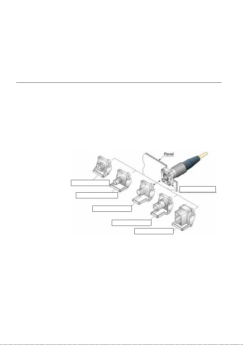
FC Adapter (EUFCAD)
DIN Adapter (EUDINAD)
LC Adapter (EULCAD)
ST Adapter (EUSTAD)
SC Adapter (EUSCAD)
PC or APC Connector
Universal connectors and adapters
Removing a
module
1 Unscrew the two captive fixing screws of the module complete ly (up
to the stop).
2 Remove the two slots of the module from their housing onto the
base.
3 Carefully remove the module ou t of its slo t.
Universal connectors and adapters
OTDR modules may be equipped with a universal connector and adapter
selected at time of order.
Adapter types
JDSU offers 5 different adapters, all compatible with this connector,
allowing the user to switch from one adapter to another according to
which fiber type he intends to work with.
Adapter types supplied are: FC, SC, DIN, ST and LC.
adapter type
10
Switching
Fig. 4 5 different types of adapters may be mounted on the
universal connector
In order to switch from an adapter to another, proceed as shown.
User Manual 770000102/08
Page 31

Universal connectors and adapters
Pull out in the direction of the
arrow in order to release the
adapter from the lug holes
To place an adapter, position
the handle as shown in order to
engage with the the lugs, push
hard and pull the handle down
Fig. 5 Removing and refitting an adapter
Chapter 2 Starting up
Changing the
adapter on a LA
OTDR Module
The LA modules are equipped with specific connector and adapters.
The adapters available are FC or SC adapters, screw type.
To mount a new adapter onto the LA Module:
1 Unscrew the two screws of the adapter currently mounted onto the
connector.
2 Remove the adapter
3 Set the new adapter vertically on the optical connec tor , maki ng flush
the «mark» on the adapter with the mark on the connector.
Fig. 6 Position of the adapter onto the connector
4 Fix the adapter with the two screws.
User Manual 770000102/08 11
Page 32

Chapter 2 Starting up
Universal connectors and adapters
Fig. 7 Fixing the adapter
Once adapter is mounted, the module is ready to be used onto the
Base-Unit.
Cleaning
universal
connectors
Remove the adapter in order to access the ferrule and clean it using a
cotton swab.
12
User Manual 770000102/08
Page 33

Chapter3
Activating OTDR function
3
Once the OTDR module is correctly set onto the equipment and the T-
BERD/MTS is switched on, the desired OTDR function must be selected
before any OTDR configuration, or measurement.
The topics discussed in this chapter are as follows:
– "Selecting the SmartOTDR™" page 14
– "Selecting the OTDR Expert function" page 15
User Manual 770000102/08 13
Page 34

Chapter 3 Activating OTDR function
Selecting the SmartOTDR™
Selecting the SmartOTDR™
Principle of the
SmartOTDR™
Selecting
SmartOTDR™
The SmartOTDR™ is used to perform OTDR acquisitions using a pre
loaded configuration file (no setup required) and access to essential
analysis features.
The SmartOTDR™ function is available whatever is the OTDR module
set onto the T- BERD/MTS.
To select this function, after the equipment starts:
1 Press the H
Fig. 8 Home page
2 Select the SmartOTDR™ icon
OME button
14
The icon turns yellow .
After a few seconds, the Results page displays.
NOTE
The selection of SmartOTDR™ icon automatically deselects the
ExpertOTDR icon and vice-versa.
NOTE
In the case a Singlemode/Multimode module, one line contains the
Multimode icons and a second one the Singlemode icons.
To distinguish both modes, multimode icons contain the MM mark.
User Manual 770000102/08
Page 35

Selecting the OTDR Expert function
Chapter 3 Activating OTDR function
Selecting the OTDR Expert function
Principle of the
OTDR Expert
Selecting OTDR
Expert
The OTDR Expert is used to
– perform OTDR acquisitions with full OTDR setup capabilities, and
advanced analysis features.
– create configuration files that can be loaded by SmartOTDR™
users.
The OTDR Expert function is available whatever is the OTDR mod ule set
onto the T-BERD/MTS.
To select this function, after the equipment start:
1 Press the H
2 Select the OTDR Expert icon
The icon turns yellow .
After a few seconds, the Results page displays.
NOTE
The selection of OTDR Expert icon automatically deselects the SmartOTDR™ icon and vice-versa.
NOTE
In the case a Singlemode/Multimode module, one line contains the
Multimode icons and a second one the Singlemode icons.
OME button
User Manual 770000102/08 15
Page 36

Chapter 3 Activating OTDR function
Selecting the OTDR Expert function
16
User Manual 770000102/08
Page 37

Chapter4
Configuring the reflectometry
test
4
Pressing the START/STOP key is all that is needed to start or stop a
measurement. However, it is necessary to configure the measurement
and the type of results desired.
This chapter describes the different sta ges in configuring a reflectometr y
measurement using an OTDR module, in SmartOTDR™ or OTDR
Expert.
The topics discussed in this chapter are as follows:
– "Configuring the unit for SmartOTDR™" page 18
– "Configuring the test in OTDR Expert" page 20
User Manual 770000102/08 17
Page 38

Chapter 4 Configuring the reflectometry test
Configuring the unit for SmartOTDR™
Configuring the unit for SmartOTDR™
Once the SmartOTDR™ icon is validate, the Results page displays
automatically.
Before any test in SmartOTDR™:
1 select the configuration file, which contains all acquisition parame-
ters and file storage setup, and which has been created in Expert
mode (see “Saving configuration parameters in a file” on page 33).
2 the user can then configure some parameters before starting the
test
Selecting the
configuration
file
To load the configuration file to be used for SmartOTDR™ test:
1 Press F
2 In the Explorer page, on the left of the screen, select the storage
3 Select the file on the right list: icon / type: .Config.
4 Press Load > Load as SMART Config. menu keys.
ILE hard key.
media and directory into which file configuration is saved.
A beep is emitted to validate the selection of the configurat ion file.
Fig. 9 Load file as SmartOTDR™ Configuration
5 Press R
acquisition with the pre loaded configuration.
NOTE
Some configuration files are available into the equipment, in disk/
config.
ESULTS hard key to go to results page and perform OTDR
18
User Manual 770000102/08
Page 39

Chapter 4 Configuring the reflectometry test
Configuring the unit for SmartOTDR™
Modifying some
parameters
before the
acquisition
In SmartOTDR™ mode, the user have access to 4 parameters he can
modified before launching the test.
To display and modify i necessary the parameters:
1 Once Results page is displayed, press S
The Setup page for OTDR acquisition in SmartOTDR™ mode
displays.
ETUP hard key
Fig. 10 SmartOTDR™Setup page
Laser The acquisition will be carried out on the
wavelength(s) selected (for multiple-wavelength
modules). In case of a multi-wavelength module,
select All to perform a measurement for all the
wavelengths available (this parameter visible
exclusively on modules with one single OTDR
port). The possible values depend on the module
used.
Fiber Number Modify, if necessary, the number of the fiber
using left and right direction keys.
Distance unit select the unit to be used for distan ce (km / kfeet
/ miles / meter / feet).
Config. This parameter displays the configuration file
selected for SmartOTDR™ acquisition, and
cannot be modified
The configuration file can be downloaded from the Setup page, pressing
the Load Config. menu key.
.
Press R
sition (it can be launched directly from the Setup page).
User Manual 770000102/08 19
ESULTS hard key to return to results pag e and launch the acqui-
Page 40

Chapter 4 Configuring the reflectometry test
Configuring the test in OTDR Expert
Configuring the test in OTDR Expert
Once the OTDR Expert icon is selected, the Results page automatically
displays.
In OTDR Expert, the parameters for acquisition and for file storage can
be configured.
1 To call up the test configuration window, press the
Dialog boxes and menu keys on the same screen enable selection
of
– Acquisition parameters
Used for the OTDR acquisition– Alarms parameters
– Measurement parameters
–Link parameters
– File parameters
Used for the OTDR results saving
SETUP button.
20
Fig. 11 OTDR setup in OTDR Expert mode
In these windows, the parameter selected is in video inverse.
User Manual 770000102/08
Page 41

Chapter 4 Configuring the reflectometry test
Configuring the test in OTDR Expert
Configuring the
Acquisition
parameters
Parameters Laser
You can choose the OTDR acquisition parameters.
1 Once the Setup page is displayed, press Acquisition menu key to
configure the Acquisition parameters.
The Acquisition Setup page is divided into two part s: the Acquisition box
and the Launch cable box.
If some acquisition parameters are not accessible (not visible or displayed in grey), check in the Home page that the OTDR Expert function has really been selected (see "Selecting the OTDR Expert
function" page 15).
The acquisition will be carried out on the wavelength(s) selected (for
multiple-wavelength modules). In case of a multi-wavelength module,
select All to perform a measurement for all the wavelengths available
(this parameter visible exclusively on modules with one single OTDR
port). The possible values depend on the module used.
Acquisition
Select the kind of acquisition to be performed:
Manual The acquisition parameters Pulse / Range / Resolu-
tion can be set by user.
Auto The acquisition parameters Pulse / Range / Resolu-
tion are defined automatically and cannot be modi-
fied
The Measurement time will be set to Auto, but can be modified.
Range
The possible range depends on the pulse length selected. This range is
given for each pulse length in the paragraph "Ranges" p age 147. This
parameter is exclusively configurable if Acquisition parameter is set to
Manual. It depends on the module used
Auto allows to detect automatically the range.
In Auto mode, the range is selected as a functi on o f the end of the fibe r.
Pulse
From 3ns to 20µs according to module used. Parameter sele ct able on ly
if Acquisition parameter is set to Manual.
See "Typical specifications" page 145.
User Manual 770000102/08 21
Page 42

Chapter 4 Configuring the reflectometry test
Configuring the test in OTDR Expert
NOTE
According to the value selected for Pulse parameter, the Range
parameter can be automatically modified, and vice-versa.
Resolution
This parameter is exclusively configurable if Acquisition parameter is
set to Manual.
Auto resolution is selected automatically according to the
High Resolution the highest resolution is applied
High Dynamic the highest dynamic is applied
Time
Real time the equipment performs up to ten acquisitions per
NOTE
Whatever is the acquisition mode selected, an acqui sit io n in re al t i me
mode can be launched maintaining the
for about 2 seconds.
last two parameters above.
second (see "Performing OTDR acquisitions" page
38).
START/STOP button pushed
22
NOTE
If the Acquisition parameter is defined to Auto, then the Time
parameter is defined to Auto, but can be modified.
Manual Enter the acquisition time desired (from 5 s. to 5
minutes max).
Predefined Select one of the acquisition times predefined: 10
seconds / 20 seconds / 30 seconds / 1 minute / 2
minutes / 3 minutes.
Smart Acquisition
This parameter allows to launch a short acquisition before the standard
one.
The first acquisition is performed with the sho rtest pulse in order to detect
more precisely the events at the beginning of the fiber.
To configure the Smart Acq. parameter:
User Manual 770000102/08
(not available in Multimode)
Page 43

Chapter 4 Configuring the reflectometry test
Configuring the test in OTDR Expert
Auto a first short acquisition is performed with the shortest
pulse in the range, before the standard one.
No the standard acquisition is directly launched.
If the option OptiPulse is available, see “Configuring th e OTDR acquisi -
tion with OptiPulses mode” on page 68 to configure the OTDR acquisi-
tion with this option.
Otdr Connector test
This parameter allows to choose if a test of the front connector must be
performed when acquisition is launched.
No the OTDR connection is tested with indication Bad/
Good.
Yes & Continue the OTDR connection is tested, and if the state is not
good, the acquisition continues but a warning
displays.
Yes & A bor t the OTDR connection is tested, and if the state is
bad, a warning displays and the acquisition stops.
Launch cable
parameters
Launch Cable End / Receive Cable Start
No All the results are displayed and referenced on the
basis of the board of the module.
Evt 1, 2, 3 The results relating to the launch cabl e are eliminated
from the table. Attenuation and distances are then
measured on the basis of the marker Evt 1, 2 or 3
selected.
Distance Use the Edit Number key to enter a distance (Min= 0
/ Max=50 km / 164.042 kfeet / 31.075 miles) or affect
the active cursor value, using the Set Cursor
Distance key.
Include Link Start Connector / Include Link End Connector
Defining the Launch Cable End parameter with an event number or a
distance will automatically activate the corresponding parameter Include
Link Start Connector. This parameters can be set to Yes if the budget
must include the connectors loss of the launch cable at end
Defining the Receive Cable Start parameter with an event number or a
distance, will automatically activate the corresponding parameter
Include Link End Connector. This parameters can be set to Yes if the
budget must include the connectors loss of the launch cable at start
If those parameters are set to No, the budget only displays the connector
loss of the fiber.
User Manual 770000102/08 23
Page 44

Chapter 4 Configuring the reflectometry test
Configuring the test in OTDR Expert
Configuring the
Alarms
parameters
If one parameter is selected, click on Next menu key to follow the OTDR
configuration and define the Alarms parameters or click on the Acquisi-
tion header and press one of the menu key Alarms, Measur’t, Link or
File to configure the selected parameters.
Once the Alarms page is displayed, configure the parameters for
applying thresholds to results displayed.
Threshold
None The alarm function is not active.
User This menu lists possible major alarm thresholds that
the user can select.
Thresholds can be defined for: Splice Loss / Connector Loss / PON
Splitter Loss / Reflectance / Slope / Fiber Length Min and Max / Total
Loss Min and Max / ORL.
TIA-568 C / ISO/IEC 11801 / JDSU Default
Select one of this parameter to configure the alarm
thresholds with predefined values:
Tab l e 1 Singlemode Modules
JDSU Default TIA-568C & ISO/IEC 11801
Splice Loss > 0.20 dB > 0.30 dB
Connector Loss > 0.50 dB > 0.75 dB
a
Slope
Reflectance > - 35 dB ORL < 27 dB -
a. This parameter is not available in OEO-OTDR configuration
> 1.00 dB/km > 1.00 dB/km
24
Tab l e 2 Multimode Modules
JDSU Default TIA-568C & ISO/IEC 11801
Splice Loss > 0.20 dB > 0.30 dB
Connector Loss > 0.50 dB > 0.75 dB
Slope 850 nm > 3.50 dB/km > 3.50 dB/km
Slope 1300 nm > 1.50 dB/km > 1.50 dB/km
Reflectance > - 35 dB ORL < 27 dB -
If results are above those thresholds, they are highlighted in red in the
table of results, and the icon appears at the top right of the screen.
User Manual 770000102/08
Page 45

Chapter 4 Configuring the reflectometry test
Configuring the test in OTDR Expert
If all the results lie withi n the thresholds (no result is in red or yellow), they
are displayed in green in the table and the icon is displayed at the
right top of the trace.
Configuring the
Measurement
parameters
Measurement
parameters
In the Setup page, press Measur’t softkey, or press Next if one parameter is selected in the current screen until the Measurement Setup p age
displays.
The Measurement Setup page is divided into two p arts: the Parameters
box and the Detection box.
Section Attenuation
dB/km Displays the section slope in the table of results.
When the fiber is too short to measure the slope
accurately, no value is displayed (empty field).
dB Displays the section Loss in the table of results. With
short fiber where the slope cannot be measured with
a good accuracy, the loss in dB is approximate and
displayed.
None The section attenuation and Loss values are not
displayed in the table of results.
Index of refraction
Choice of group refraction index of the whole fiber.
User Define for each wavelength (1310 SM, 1360-1510
SM, 1550 SM, 1625 SM) a refraction index of
1.30000 to 1.69999. The selection of an index alters
the value of the section AB (actual distance between
cursors A and B).
or,
If the actual distance between the cursors A and B is
known, enter its value under Section AB to establish
the index of the fiber. Selection of this distance
causes the display of the indices. The extreme
distance values are given by the index values
(1.30000 à 1.70000).
Predefined It is possible to choose one of the predefined values
given for certain cables. The corresponding indices
given in the table below are repeated on the screen.
User Manual 770000102/08 25
Page 46

Chapter 4 Configuring the reflectometry test
Configuring the test in OTDR Expert
Wavelength (nm) 1310 SM 1360 - 1510 SM 1550 SM 1625 - 1650 SM
Generic G652 G657 1.46750 1.46800 1.46800 1.46850
Generic G653 G655 1.46750 1.46800 1.46800 1.46850
ATT SM 1.46600 1.46700 1.46700 1.46700
Corning SMF-28 1.46750 1.46810 1.46810 1.46810
Corning SMF-DS 1.47180 1.47110 1.47110 1.47110
Corning SMF-LS 1.47100 1.47000 1.47000 1.47000
Corning-Leaf 1.46890 1.46840 1.46840 1.46900
Draka SMF 1.46750 1.46800 1.46800 1.46850
Draka Longline 1.46700 1.46700 1.46710 1.46750
Draka Teralight 1.46820 1.46820 1.46830 1.46850
Draka Benbright 1.46750 1.46750 1.46800 1.46850
Fitel Furukawa 1.47000 1.47000 1.47000 1.47000
OFS Lucent Allwave 1.46750 1.46750 1.46750 1.46850
Lucent Truewave 1.47100 1.47100 1.47000 1.47000
SpecTran SM 1.46750 1.46810 1.46810 1.46810
Sterlite 1.46700 1.46700 1.46750 1.46750
Sumitomo Litespec 1.46600 1.46600 1.46700 1.47000
Sumitomo Pure 1.46600 1.46600 1.46700 1.47000
26
Fig. 12 Predefined index values (Single Mode)
Wavelength (nm) 850 MM 1300 MM
Corning 62.5 1.50140 1.49660
Corning 50 1.48970 1.48560
SpecTran 62.5 1.49600 1.49100
Generic 50 1.49000 1.48600
Generic 62.5 1.49000 1.48700
Generic OM1-62/125 1.49600 1.49100
OM2-3- 4 50/125 1.48200 1.47700
Fig. 13 Predefined index values (Multi Mode)
User Manual 770000102/08
Page 47

Chapter 4 Configuring the reflectometry test
Configuring the test in OTDR Expert
Scatter coefficient
User Selects for each wavelength, the backscatter coeffi-
cient of -99 dB to -50 dB by increments of 0.1dB.
Modification of the backscatter coefficient K changes
the measurements of reflectance and ORL.
Auto Backscatter coefficients are selected automaticall y for
each wavelength.
In Multimode, two predefined scatter coefficients are available:
– Generic 50: 850 MM - > -66.3 dB
1300 MM -> -73.7 dB
– Generic 62.5: 850 MM -> -66.1 dB
1300 MM -> -70.3 dB
The default values are given in the paragraph "Reflectance" page 3.
Distance Unit
Define the unit of the distances displayed: km, kfeet, miles, meter, feet.
Results on trace
None the trace alone
All the trace with results and markers.
Graphics the trace with markers only.
If All or Graphics is selected, the reflectometry trace is disp layed with a
dotted vertical line set on the end of launch cable (if the Launch
Cable is defined in the
of fiber .
SETUP menu) and a dotted vertical line on the end
Detection
parameters
Otdr Connector Measurement
This parameter allows to choose if a measurement of the front con nector
must be performed when acquisition is launched.
No In the results table, the first l ine corresponds to the
first event detected.
Yes In the results, the first result corresponds to the front
connector measurement, at 0 meter (estimated
value).
Splice
Select if a level of detection for splice must be defined.
User Manual 770000102/08 27
Page 48

Chapter 4 Configuring the reflectometry test
Configuring the test in OTDR Expert
Press Edit Number soft key and select a value:
– Enter a min level of detection, from 0.01 to 1.99 dB
– No: no splice detection
– Auto: to automatically detect splice
Reflectance
Select if level of detection for reflecta nce must be defined.
Press Edit Number soft key and select a value:
– Enter a min level of detection, from -98 to -11 dB
– None: no reflectance detection
– All: all reflectances are detected
Ghosts
Choice (Yes / No / No Analysis) of whether information relating to
ghosts is to be displayed. If ghosts are displayed, the reflection icon in
the table of results appears dotted and the reflection value is displayed
in brackets on the trace, for example «(R:-50 dB)».
28
PON Splitter
Once parameter is selected, press Edit Number key to display the
numeric keypad and select the wished value:
None there is no splitter set onto the network.
Auto each event being > to 3dB is considered as a splitter.
Events which are < to 3 dB are displayed as splices or connectors.
1 to 21 dB (steps of 1 dB): each event superior to the custom-
(not available in Multimode)
ized value is considered as a splitter. The events
below this value are displayed as splices, bends or
connectors.
Fiber end
Once parameter is selected, press Edit Number key to display the
numeric keypad and select the wished value:
Auto (recommended) option in which the T-BERD/MTS
automatically detects the end of a fiber.
3 to 20 dB (steps of 1 dB): threshold of detection of end of fiber.
User Manual 770000102/08
Page 49

Chapter 4 Configuring the reflectometry test
Configuring the test in OTDR Expert
Bend
(not available in Multimode)
With any dual or triple-wavelength measurement module, the user will
have access to the macro bend detection functi on in the test setup. Each
event of the selected wavelengths will then be compared.
Once parameter is selected, press Edit Number key to display the
numeric keypad and select the wished value:
None Bend will not be detected.
Auto Bend will be automatically detected.
Define by user Enter the bend value (in dB), with direction keys or
numeric keypad.
Configuring the
Link
parameters
In the Setup page, press Link softkey, or press Next if one parameter is
selected in the current screen until the Link Setup page displays.
The information entered in the Link Description window concerns the
editing and/or the modifications of t he cable and fiber p arameters. When
a trace is recalled without recall of the configurat ion, the parameters of
this trace will be present only in its signature.
Fiber ID and Fiber Number
1 Select the parameter Fiber Id and enter a name for the fiber, using
the edition keypad.
2 Select the parameter Fiber Number and modify the number of the
fiber to be tested.
The fiber number can be automatically incremented/decremented at
each new file save if it has been configured in the File Setup page (see
"Change Fiber Nbr" page 32).
Cable Id
This parameter allows to enter an identification of the cable, using the
Edition menu.
Direction
The direction shows if the acquisition has been made from the origin to
the extremity (A->B) or from the extremity to the origin (B->A). Changing
direction makes it possible, when different extremities are handled, to
see the parameters of the fiber for the other extremity.
Location A
The name of the Location A of the link may be entered here.
User Manual 770000102/08 29
Page 50

Chapter 4 Configuring the reflectometry test
Configuring the test in OTDR Expert
Location B
The name of the Location B of the link may be entered here.
Operator
Use the arrow to enter the name of the operator carrying out the
measurement.
Comment
In contrast to the other data in this menu, the comment is specific to a
fiber. Thi s line is thus used to enter a new comment and not to display it.
The comment appears at the top of the screen, with the other parameters
of the fiber.
This comment will remain available for the next acquisition, unless it is
deleted. It is also saved when a trace is saved with a comment.
Configuring the
file storage
parameters
The File storage parameters must be also configured, i n order to defi ne
how the results traces will be saved onto the T-BERD/MTS.
In the Setup page, press File softkey, or press Next if one parameter is
selected in the current screen until the File Setup page displays.
Dir
This parameter cannot be configured, and di splay the direc tory selected
by default into which the file(s) will be save d (the last directo ry selected).
To modify the directory, go to the Explorer page and select another
directory.
Filenaming
Select Filenaming parameter and press the right arrow key to modify the
name of the file for the result trace.
In the edition keypad, enter a name manually for the fil e and/or use
the predefined parameters available (Cable_Id, Fiber_Num...).
Then, press Enter to validate.
30
User Manual 770000102/08
Page 51

Chapter 4 Configuring the reflectometry test
Predefined
parameters for
naming files
Configuring the test in OTDR Expert
Fig. 14 Filenaming - Edition keypad
or
Press Default Filename to apply the name by default to the file:
Fiber[Cable_Id][Fiber_Num]_[Lambda]_[Direction][Pulse]
The name of the file is displayed in grey under Filenaming parameter
File Content
In this parameter, select the file content for traces saving:
One Trace in case of traces in overlay, each trace i s saved in a
distinct file (.sor extension).
All Traces in case of traces in overlay, all traces are saved in
one single file (.msor extension).
Save Mode
When a trace or more is displayed, in the p arameter Save Mode, you can
select three types of methods for storing traces:
– File Only: only the trace(s) is/are stored in one/several file(s), with
its extension (.sor, .msor)
– File + txt; the trace(s) is/are stored in one/several file(s), with its
extension and one txt file is also generated.
– File + pdf: the trace(s) is/are stored in one/several file(s), with its
extension and one pdf file is also generated .
Auto Store
Select Yes to store automatically the trace or trace s resulting from each
acquisition according to the filenaming rules.
User Manual 770000102/08 31
Page 52

Chapter 4 Configuring the reflectometry test
Configuring the test in OTDR Expert
Change Fiber Nbr
Increment the fiber number is automaticall y incremented at each
Decrement the fiber number is automatically decremented at
No the Fiber number must not automatically modified.
new file-save.
each new file-save
Configuration
in Test Auto
mode
The Test Auto key imposes the parameters for acquisition, measure-
ment and display of results defined as default settings in factory.
Tab l e 3 Acquisition parameters in Test Auto mode
Tab Acquisition Tab Launch Cable
Laser: All Launch Cable End: No
Acquisition: Auto Launch Cable Start: No
Time: Auto
Smart Acq: No
OTDR Connector Test: Yes & Cont
Alarms parameters in Test Auto mode
Thresholds: None
Tab l e 4 Measurement parameters in Test Auto mode
Tab P a r ameters Tab Det e c t i on
Section Attenuation: dB/km OTDR Connector Meas: No
Index of Refraction: G652 G657 Splice: Auto
Scatter Coefficient: Auto Reflectance: All
Results on trace: Graphics Ghost: No
PON Splitter: None
Fiber End: Auto
Bend: Auto
32
Tab l e 5 File configuration in Test Auto mode
File
Filenaming: Auto filenaming:
Fiber[Cable_Id][Fiber_Num]_[Lambda][Direction]
User Manual 770000102/08
Page 53

Chapter 4 Configuring the reflectometry test
Directory into
which file will
be saved
Configuring the test in OTDR Expert
Tab l e 5 File configuration in Test Auto mode
Auto Store: Yes
Change Fiber Nbr: Increment
Saving
configuration
parameters in a
file
Once File and Measurement parameters have been configured, those
parameters can be kept in memory and saved in a configu ration file.
This configuration file can then be recalled in two cases:
– in order to be applied when acquisition in SmartOTDR™ mode is
performed.
– in order to be recalled for future acquisition in OTDR Expert
To save parameters in a configuration file:
1 If necessary, press
2 Select one parameter in one of the setup page (acquisition, link..)
3 Press menu key .
An edition keypad displays
4 Enter a name for the configuration file.
NOTE
Configuration file is saved by default in the directory disk/config.
SETUP to return to Setup page.
Fig. 15 Save Configuration file - Edition keypad
5 Press Enter to validate
The configuration file is saved with the extension .fo_cfg (icon ).
User Manual 770000102/08 33
Page 54

Chapter 4 Configuring the reflectometry test
Configuring the test in OTDR Expert
This configuration file can be selected in SmartOTDR™ (see "Selecting
the configuration file" page 18) or loaded for ExpertOTDR.
Loading an
existing
configuration
file in
ExpertOTDR
T o load a confi guration file previously created o r available in the T -BERD/
MTS and apply parameters to new OTDR Expert tests:
From the File Explorer page
1 Press FILE hard key
2 Select the configuration file desired
3 Press Load > Load Config.
– Press S
You can modify some acquisition or file storage parameters, and save
them in a new configuration file (see “Savin g configuration parameters in
a file” on page 33).
ETUP hard key to display the OTDR acquisition parameters
saved in the selected configuration file.
From the Setup page
1 Select one header in either Setup page (Acquisition, Link, File...)
2 Press Load Config. menu key.
The file Explorer page displays
3 Select the configuration file desired
4 Press Load Config. to load the configuration file for acquisition in
OTDR Expert mode.
A sound is emitted to confirm the loading.
The Setup screen is displayed again.
34
If the menu key Load as SMART Config. is pressed, the configuration is applied for acquisition in OTDR Expert, and in SmartOTDR™
mode too.
NOTE
Some configuration files are available into the equipment, in disk/
config.
User Manual 770000102/08
Page 55

Chapter 4 Configuring the reflectometry test
Configuration file will
be used for Expert
OTDR acquisition
only
Configuration file will
be used for Expert
OTDR and SmartOTDR acquisitions
The main parameters available in the selected
configuration file are displayed in the File signature.
Configuring the test in OTDR Expert
Fig. 16 Loading a configuration file
User Manual 770000102/08 35
Page 56

Chapter 4 Configuring the reflectometry test
Configuring the test in OTDR Expert
36
User Manual 770000102/08
Page 57

Chapter5
Launching a reflectometry
test and displaying results
5
Once the configuration for acquisit ion and file storag e has been define d,
the instrument is ready to launch an OTDR measurement.
Pressing the S
OTDR measurement on the T-BERD/MTS.
This chapter describes the different stages in a reflectometry measurement made using an OTDR module. It then describes the functi ons available on trace(s).
The topics discussed in this chapter are as follows:
– "Performing OTDR acquisitions" page 38
– "Results display" page 45
– "Advanced functions in OTDR Expert mode" page 54
– "SLM (Smart Link Mapper) option" page 65
– "OptiPulses option" page 68
– "Saving the trace(s) and generating a report" page 70
– "Storing OTDR measurements" page 73
User Manual 770000102/08 37
TART/STOP key is all that is needed to start or stop an
Page 58

Chapter 5 Launching a reflectometry test and displaying results
Performing OTDR acquisitions
Performing OTDR acquisitions
Performing an
acquisition in
Real Time mode
Principle of the
Real time mode
Performing
acquisition in Real
Tab l e 6 Connection indicator
State Connection
Good The connection is OK
Bad – There are several connectors close to the external connector of the MTS/T-BERD.
– One of the connectors is dirty or badly connected. Replace the la unch cable, make
the connection again properly or clean the connector of the OTDR or of the jumper.
– No fiber is connected.
Acquisition in real time must not be used if a precise measurement is
required because of the high noise level, but it is suff ici ent for rapi d opt imization of a connection and for obs erving a fiber in process of utilization.
To carry out an acquisition in real time:
Time
1 Hold the S
the acquisition in real time
or
If the Time parameter is defined with Real Time in Setup page in
OTDR Expert mode, press S
The red Testing indicator will go on to show that real time acquisi-
tion is in progress. The trace acquired is displayed in real time.
An indicator of the state of the connection ( Good/Bad) is displayed
below the trace:
TART/STOP key down for about three seconds, to launch
TART/STOP hard key.
38
If the state of the connection is bad, it is still possible to carry out a
measurement, but the results will not be very reliabl e.
User Manual 770000102/08
Page 59

Chapter 5 Launching a reflectometry test and displaying results
Performing OTDR acquisitions
Fig. 17 Example of acquisition in Real Time (with OTDR
)
Expert
Traffic detection
Traffic on the fiber under test is automatically detected and reported.
Stopping the real
time acquisition
Press the
cates there is traffic on the fiber and asks you if you wish to continue or
not:
– If you click on
– If you click on
NOTE
If the measurement is validated despite the traffic (key
measurement will be automatically performed, even if traffic is still
detected on fiber.
If the measurement is cancelled (key
pushed another time, the box asking if you wish to continue or not is
displayed.
The functioning of Traffic Detection is then indicated in the scaled down
representation of trace, on the upper left part of screen .
During an acquisition in real time, several actions can be made on results
in progress: see "Actions on trace during acquisition" page 43.
To stop or interrupt an acquisition in real time mode, press the START/
TOP key at any time.
S
User Manual 770000102/08 39
START/STOP key to begin the measurement. A message indi-
NO, the measurement is not launched.
YES, the measurement is performed, despite the
traffic.
YES), the next
NO), and the START/STOP
Page 60

Chapter 5 Launching a reflectometry test and displaying results
Number of
averages calculated
Total acquisition timeElapsed time
Performing OTDR acquisitions
Performing a
measurement
with
SmartOTDR™
The acquisition is carried out with the parameters saved in the Configuration file. It may be stopped at any time using the
At the end of test, the results page displays.
1 Press S
2 The quality of the connection is displayed
3 Then, a bar graph shows elapsed and remaining acquisition time.
TART/STOP hard key to launch measurement.
The red Test indicator goes on to show that the T-BERD/MTS is in
process of acquisition and the screen displays the trace in proc ess
of acquisition.
for a few seconds (see Table 6 page 38)
START /STOP key.
Performing an
acquisition with
OTDR Expert
40
Fig. 18 Acquisition in progress in SmartOTDR™
At the end of the acquisition, a beep is emitted, and the measurements
are displayed.
NOTE
During acquisition, the traffi c on fiber is automatically detected (see
"Traffic detection" page 39)
In this mode, the T-BERD/MTS carries out a number of averagings
defined as a function of the maximum acquisition time specified in the
Acquisition menu, and then terminates the acquisition.
User Manual 770000102/08
Page 61

Chapter 5 Launching a reflectometry test and displaying results
Number of averages
calculated
Elapsed
acquisition time
Total
acquisition time
Elapsed
time
Performing OTDR acquisitions
The acquisition is carried out with the p arameters p reviousl y selected in
the Acquisition menu. It may be stopped at any time using the
TOP key.
S
START/
1 Press the
START/STOP key to start the acquisition.
The red indicator goes on to show that the T-BERD/MTS is in
process of acquisition and the screen displays the trace in process
of acquisition.
2 The quality of the connection is displayed
for a few seconds (see Table 6 page 38)
3 Then, a bar graph shows elapsed and remaining acquisition time.
Fig. 19 Acquisition in progress with OTDR Expert
At the end of the acquisition, a beep is emitted , the trace is displayed and
an automatic measurement is started.
NOTE
During acquisition, the traffic on fi ber is automatically detected (see
"Traffic detecti on" page 39)
NOTE
To stop the acquisition, the
START/STOP key may be pressed at any
time. Then an automatic measurement is carried out, but some events
cannot be detected (a manual measurement must then be made).
User Manual 770000102/08 41
Page 62

Chapter 5 Launching a reflectometry test and displaying results
Performing OTDR acquisitions
Performing an
acquisition
from Results
page
Once the results page is displayed, you can perform a new acquisition
modifying the main acquisition parameters.
Before launching a new OTDR acquisition, make sure the
trace(s) displayed have been previously saved if necessary, as
the new acquisition will automatically delete the displayed
results.
1 On Results page, press Quick Setup softkey
In OTDR Expert mode, the acquisition parameters that can be modified displays under the results trace.
In SmartOTDR™ mode, the Setup screen displays (see Figure 10
on page 19).
42
Fig. 20 Results page and Quick Setup menu (OTDR Expert)
2 Modify the acquisition parameters wished in the displayed menu:
– In OTDR Expert mode: Laser / Acquisition / Range / Pulse /
Time
See page 21 and page 22.
– In SmartOTDR™ mode: Laser / Fiber Number / Distance unit
See page 18.
3 Once configured, launch the new OTDR test pressing the S
S
TOP hard key.
Press again Mini Setup menu key to hide the menu under the trace.
User Manual 770000102/08
TART/
Page 63

Chapter 5 Launching a reflectometry test and displaying results
Performing OTDR acquisitions
Multi-
wavelength
acquisition
Actions on
trace during
acquisition
If the module possesses several lasers, to perform successive acquisitions on all the wavelengths:
1 In the
2 Start the acquisition by pressing the
3 Once the acquisition for the first wavelength is finished, the acquisi-
The different traces appear in the same win dow and can be handled similarly to overlaid traces (see "Overlay trace function" page 61).
During an acquisition, several actions are available on results in progress.
SETUP menu, check in Laser line, that several lasers are
selected (or select All if a module with onl y on e OTDR port is us ed).
START/STOP button.
tion for the following wavelength starts automatically.
or
To stop manually the acquisition for current wavelength, click on
Stop Wavelength. Th is will allow to automatically start the
measurement for the following wavelength.
Positioning Cursors A and B
1 Select Cursor A or Cursor B and:
– Set both cursors A & B to control distance between two points.
– Set one cursor A or B to get the distance from one point.
– Set one cursor A or B to zoom on this cursor
Zooming on trace
1 Select Zoom function:
– use the menu key in SmartOTDR™
– use the menu key in OTDR Expert
2 Use touchscreen or validation key to zoom in and zoom out on trace
(see “Zoom function” on page 50)
Shifting the trace (OTDR Expert only)
In OTDR Expert mode only, the trace can be shifted vertically or horizontally during the acquisition:
1 Select Shift function on menu key
2 Use touchscreen or direction keys to shift horizontally or vertically
the trace (see “Shift function (OTDR Expert only)” on page 51)
User Manual 770000102/08 43
Page 64

Chapter 5 Launching a reflectometry test and displaying results
Performing OTDR acquisitions
Displaying Trace or Summary page
1 Use the menu key Trace/Summary to display either:
– the acquisition trace in progress and the bar graph of time
– the Summary page with exclusively the bar graph of time.
In the case of measurement on several wavelengths, once a measurement is completed for one wavelength:
– the Trace function allows to display the trace and results table f or
this wavelength: once Trac e is selected, press validation key to
pass from Trace + results t able on 1 l ine to T race + resul ts t able on 4
lines, and vice-versa,
– the Summary function allows to display a summary of results for
this wavelength.
Modifying acquisition parameters (in Real Time mode only)
You can modify the acquisition parameters without returning to the
SETUP menu.
1 Press the Acquisition Param key
2 Use displayed keys to scroll through the possible values of the
various acquisition parameters.
44
Fig. 21 Example of acquisition in Real Time
Zooming on the fiber end (in Real Time mode only)
During a real time acquisition, you can reach the end of the fiber under
test at any time:
1 Press Zoom to End menu key.
The display automatically reaches the end of the fiber under test.
The menu key Zoom to End becomes Zoom to Start.
Press Zoom to Start to display the start of the fiber under test.
User Manual 770000102/08
Page 65

Chapter 5 Launching a reflectometry test and displaying results
Results display
Performing measurements during acquisition (Real Time mode only)
The real time mode allows to make Loss, ORL or Reflectance measurement using the A & B cursors and the key Loss / ORL / Reflect.:
1 Position A & B cursors on the trace
2 Click as many times as necessary on key to get the
measurement between A & B cursors.
Fig. 22 Example of loss measurement
Results display
The traces acquired or recalled from a memory are displayed on the
Results page. According to the mode of acquisition (OTDR Expert or
SmartOTDR™), the results page offers simil ar functions, but also
different functions.
User Manual 770000102/08 45
Fig. 23 Example of results trace with SmartOTDR™
Page 66

Chapter 5 Launching a reflectometry test and displaying results
Results display
Fig. 24 Example of results trace with OTDR Expert
– On the upper right side, the alarm icon is displayed (if some alarm
thresholds are defined in the pre loaded configuration file).
Tab l e 7 Alarms display
Fail Indicates that at least one result exceeds the alarm thresh-
olds defined in the configuration file used for acquisition
Results are displayed in red in table.
Valid Indicates that all the results lie within the threshol ds (no
result is in red or yellow).
Results are displayed in green in the table.
Common
functions
Display of events
on the trace
46
Each event detected is referenced under the trace by a serial number.
The reflectometry trace is displayed with a dotted vertical line set on the
start of launch cable (if the Launch Cable End parameter is defined
in the
SETUP menu)
The trace can also be displayed with a dotted ve rtical line on the end of
fiber .
The icon is displayed on trace if the Receive Cable Start param-
eter has been defined in the Setup menu.
The results of the measurements of attenuation, reflectance and slope
can be marked on the trace.
The reflectance of a ghost event is displayed in brackets on the trace.
User Manual 770000102/08
Page 67

Chapter 5 Launching a reflectometry test and displaying results
Results display
Criteria for display of an event
An event will be displayed if it s attenuation or it s reflectance e xceeds the
corresponding threshold selected in the
the test in OTDR Expert" page 20). Attenuation and reflectance results
for an event will be displayed if they can be calculated
The reflectance of an event is always measured except when the event
causes a saturated Fresnel peak or if it is drowned out by noise. In this
case, the T-BERD/MTS displays > to show that the actual reflectance
exceeds the value displayed.
When there is saturation for a reflective event, the maximum val ue
measured is displayed with the sign >. This shows th at the act ua l ref lectance is greater than the value shown (for example, if R >-29,5 dB is
displayed, the reflectance could be -18dB)
SETUP menu (see "Configuring
Results table
Under the trace is displayed the resul ts table with all the event s detected
during acquisition.
– In SmartOTDR™, the 4 lines table is always displayed under trace.
– In ExpertOTDR mode, once Trace is selected, press validation key
to pass from Trace + results table on 1 line to Trace + results
table on 4 lines, and vice-versa
A table with one line displayed under the trace and giving the type
and characteristics of the event nearest to the cursor.
A table giving the type and the characteristics of all the events
detected during the measurement: the 4 first lines displayed correspond to the 4 first events nearest to the cursor. The line corresponding to the event nearest to the cursor is highlighted. This
highlighting moves if the cursor is moved.
Fig. 25 Example of trace and results table
User Manual 770000102/08 47
Page 68

Chapter 5 Launching a reflectometry test and displaying results
Results display
At the top of the table, a line shows the generic parameters of the fiber:
numbers of events present, total ORL of the link and, in ExpertOTDR
mode, reference trace icon (if trace is the reference trace - see “Refer-
ence Trace function” on page 63).
Each event is referenced under the t race by a nu mber which is repeated
in the first column of the table. The table then shows:
– icon symbolizing the type of the event:
Receive cable Start
Launch cable End: the attenuation and dist ances are measured
on the basis of the corresponding marker.
Non-reflecting attenuation (e.g. splice).
Splitter.
Event with Reflectance. (e.g. connector)
Ghost reflection.
Slope of the fiber (when no fault follows the slope).
End of fiber
OTDR connector
48
Event marker when a measurement cannot be carried out . If the
event to be added is too close to an existing event, the icon
appears on the trace and the table, but no measurement is
carried out: to obtain the results fo r this event, a manual
measurement is necessary.
The event underlined in yellow is the one the nearest of the cursor set on
trace. To visualize an event, click on this event on the table to set the
cursor on it onto the trace.
Click on one event icon in the resul ts t able t o di splay the event type and
the alarm threshold defined for this event (if Ala rms have been defined in
the Setup page).
If the value of the event selected exc eeds the defined threshold, t hen the
possible causes for this alarm are described in the window:
User Manual 770000102/08
Page 69

Chapter 5 Launching a reflectometry test and displaying results
Click
Results display
Fig. 26 Event description
The following columns are then displayed next to each event icon:
Cursors
Distance
Loss
Reflect.
Slope
(OTDR Expert
only)
Section
(OTDR Expert
only)
T. L o ss
The cursors A and B are represented by vertical lines of different colors:
– in a solid line if the cursor is selected.
– in a dotted line if the cursor is not selected.
The distance of the event from the beginning of
the fiber, in meters (or miles)
The attenuation due to the event, in dB
The reflectance of the event, in dB
The slope before the event, in dB/km (or dB/kft) if
it can be measured
The length of the section = the distance between
the marker of the event and the previous marker.
The total attenuation of the fiber (total loss), in dB
Positioning the cursor
1 Press the key to active the cursor.
2 Touch the screen on the required location on trace where the active
cursor must be set.
You can also use the direction keys and to move the selected
cursor along the trace
User Manual 770000102/08 49
Page 70

Chapter 5 Launching a reflectometry test and displaying results
First
press
Second press
Zoomed area
Results display
Above the trace is shown the 2-points loss measurement between the
two cursors, together with the distance between the two cursors.
The cursors data are displayed exclusively if the Cursor menu
key is active. If another key is active, the display shows help
tooltips, different according to the selected function.
When the cursor function is selected, the key s and move the trace
vertically.
Zoom function
The Zoom function is used to analyze part of the trace in greater detail.
The zoom is centred on the active cursor
.
The position of the section of trace displayed with respect to the complete
trace is represented by a red rectangle on the mini-trace at the to p lefthand corner of the screen.
Defining a zoom on the trace using the touchscreen or screen deported on PC
1 Press Zoom or Zoom/Shift softkey to activate the zoom function
– menu key in SmartOTDR™
– menu key in OTDR Expert
2 Press once in one location on the screen, which will represent the
upper left corner of the zoomed area.
The icon is displayed on the screen.
3 Press another time on the location which will represent the lower
right corner of the zoom.
50
Fig. 27 Zoom on trace using touchscre en
Defining a zoom level on the trace using direction keys
1 Select Cursor A or B and center it on the zone to be examined
2 Press Zoom softkey.
User Manual 770000102/08
Page 71

Chapter 5 Launching a reflectometry test and displaying results
Results display
3 Use the or key to increase or reduce the zoom factor, keeping
the selected cursor centered on screen.
Swapping from an automatic zoom to full trace and vice-versa
The automatic zoom allows to get an optimized display of the trace.
To apply an automatic or entire zoom on the trace:
1 Select the Zoom function on key Zoom/Shift.
2 Press validation key ( or E
Press again validation key ( or E
screen.
NTER) to apply an auto zoom on trace.
NTER) to display the trace in full
Specific functions of the zoom with a touchscreen
With the touchscreen, once the Zoom function is selected on menu key
Zoom, you can:
– maintain your finger pressed on screen and shift the traces horizon-
tally or vertically
– position your finger on a cursor and move it on trace maintaining
your finger pressed and moving it toward left or right
– once a zoom is performed, double click on the zoomed zo ne to undo
the zoom
Shift function
(OTDR Expert only)
Zooming on the different events in succession
1 Set the cursor on one event
2 Define a zoom on this event.
3 Click on another event in the results table.
The cursor is automatically positioned on this event , which is always
centered on the screen, keeping the zoom level selected.
The Shift function is used to displace the displayed section of the trace
by pressing the direction keys or directly clicking on the touchscreen.
The horizontal shift is performed maintaining the point of intersection
between the trace and the selected cursor at the same level, s crolling the
trace horizontally while followin g it vertical ly, so that it never goes of f the
screen.
To use this function:
1 Select the zoom factor as described above.
2 Choose cursor A and cursor B position.
User Manual 770000102/08 51
Page 72

Chapter 5 Launching a reflectometry test and displaying results
Results display
3 On the Zoom/Shift key, select Shift.
4 Displace trace manually on touchscreen toward left/right or upward/
backward.
or
Use the direction keys to shift the trace in the desired direction
Summary
To display a summary of the results, select Summary function on Trace/
Summary menu key.
The upper table displays a summary of result s for each wavelength onto
which measurement has been performed.
Some results can be displayed in color (green or red) if they lie within or
exceed the alarm thresholds defined in the Set up screen in ExpertOTDR
mode and defined in the configuration file used for acquisition in SmartOTDR™ mode (see “Selecting the configuration file” on page 18).
Fig. 28 Summary page & Alarms table
In the lower part of the screen, the Alarms table, gives the summary of
the alarms detected (Reflectances, Splices, Splitters, Connectors,
Bends...).
52
Select one event in the Alarm table and click on Event Diagnosis menu
key or directly on the event icon in the Alarm table to get a detailed
description of the event.
User Manual 770000102/08
Page 73

Chapter 5 Launching a reflectometry test and displaying results
Results display
Abb. 29 Summary key - Event Diagnosis
Click on Trace View softkey to return to display of T race + Res ults Table.
Display of traces in
overlay
– The traces are shown in different colors (the active trace is green).
– The mains acquisition parameters are displayed at the top of the
screen.
Fig. 30 Traces in overlay
Selecting one trace from overlaid traces
To make actions on a trace in overlay (move on events, set a cursor...),
it must first be swapped with the active trace. To do this:
1 Press the Trace key
User Manual 770000102/08 53
Page 74

Chapter 5 Launching a reflectometry test and displaying results
traces
numbers
Short acquisition
(in blue)
Standard acquisition (in green)
Advanced functions in OTDR Expert mode
2 Press the direction keys and , as many times as
necessary, until the active trace is displayed in green.
or
Click on the trace numbers in the upper right side of
the result page until the trace desired is selected.
or
Click on the upper part of the screen, in Trace information zone to
scroll the traces.
NOTE
Actions relative to traces (move cursors, move on event s.. .) are exclusively done on the active trace (in green), not on the other ones.
Traces display in
double acquisition
When a double acquisition has been performed, i.e. a short acquisition
preceding a standard one (see “Smart Acqui sition (not availabl e in Multi-
mode)” on page 22), two traces are displayed in the same window.
mode
Fig. 31 Traces display in double acquisiti on mode
The short trace is the one resulting from the short acquisition and stops
while the standard one continues until the end of measureme nt.
Advanced functions in OTDR Expert mode
Several actions on trace displayed can be performed in ExpertOTDR
mode only.
54
User Manual 770000102/08
Page 75

Chapter 5 Launching a reflectometry test and displaying results
Advanced functions in OTDR Expert mode
Automatic measurement and detection
Addition of
events
If the instrument does not detect all the expected events, additional
manual measurements can be carried out.
To delete all the markers, press the Advanced key, then select Delete.
The following procedure is recommended:
1 By default, the instrument locates the events and proceeds to the
measurements.
2 Addition of events (see “Addition of events” on page 55) in the cases
of splices showing low attenuation and of close events . The TBERD/MTS then automatically measures the slope before and after
the markers selected and measures the attenuation of the splice.
3 Addition of manual measurements if necessary (for deeper anal-
ysis). The T-BERD/MTS performs the meas urements requested by
the user.
To start an automatic measurement while a measurement is already in
progress:
1 Press the Advanced key.
2 Select Delete and press validation key ( or
3 Select Auto Meas. and press validation key ( or
You can also manually place markers in addition to those positioned
automatically during automatic measurement.
ENTER).
ENTER).
Representation of the events
The events are represented by the symbol : if they are set during a
measurement.
The events are represented by the symbol if they are set manually in
Advanced mode.
To add markers of events:
1 Select a cursor (A or B).
2 Use the direction keys or touchscreen to move the cursor to the
place where you want to position a marker.
3 Press the keys: Advanced > Set Event.
4 An event marker is displayed at the position of the cursor and a
measurement is carried out on the event.
User Manual 770000102/08 55
Page 76

Chapter 5 Launching a reflectometry test and displaying results
Advanced functions in OTDR Expert mode
Measurement of slope before the marker starts just after the
previous event (or at the end of the dead zone at the beginning of
the fiber); measurement of slope after the marker stops just before
the next marker or at the end of the fiber.
Hints on the positioning of markers
– Do not add markers (with the Set Event key) after a manual
measurement, as all the result s will be recalculate d automaticall y by
the instrument.
– If two markers are too close together, they will appear on the trace
and the table but no measurement will be carri ed ou t o n th e seco nd
marker: to obtain results for this marker, a manual measurement is
necessary.
– If you press the Set Event key when the cursor is very close to a
marker, the latter will be deleted.
Deleting events
To delete an event, move the cursor onto the event and press the Set
Event key . The event selected will be deleted and a complete measure-
ment, without this event, is carried out.
Deletion of events can cause incorrect measurement results.
Manual
measurements
Measurements of
slope
56
As soon as you have made an acquisition, with or without automatic
measurement, you can make manual measurements on any event on
the trace by means of the cursors A and B, in association with the functions of slope, detection of splice and calculation of ORL.
The manual measurements are accessible in the Results page, after
pressing the keys: Advanced, then Manual Measurement.
To make a manual measurement of slope, press the RESULTS but ton t o
call up the trace and then:
1 Place the cursor A at the beginning of the secti on of the t race wher e
the slope is to be measured.
2 Place the cursor B at the end of this section.
3 Press the Advanced key, then the Manual key, then select Slope.
4 Press validation key ( or
trace section is displayed.
User Manual 770000102/08
ENTER) : the slope of the specified
Page 77

Chapter 5 Launching a reflectometry test and displaying results
Slope
Advanced functions in OTDR Expert mode
Fig. 32 Manual Measurement results
Result of slope measurement
The result is displayed on the screen between the two slope indicators
[and].
The measurement results are also available in the table:
1 Press Exit to return to the initial results page.
2 Select Trace using Trace/Summary soft key
3 Press validation key ( or
the trace.
"Distance" shows the distance between the beginning of the trace and
the end of the slope;
ENTER) to display results table under
If no result is displayed in the table, this means that the dist ance between
the cursors A and B is too small.
Deleting a slope measurement
To delete a particular slope measurement result:
1 Superimpose the cursors A and B on the slope concerned
2 Select Slope (after, if necessary, pressing Advanced > Manual
Meas.).
3 Press validation key ( or
trace section is deleted.
User Manual 770000102/08 57
ENTER) : the slope of the specified
Page 78

Chapter 5 Launching a reflectometry test and displaying results
Advanced functions in OTDR Expert mode
Measurement of
ORL
It is possible to carry out an ORL measurement on a part of the fiber.
Follow the following procedure to measure a part of the fiber:
1 Position the cursors A and B to delimit the section that you wish to
measure.
2 Press the Advanced > Manual Measurement, then select ORL.
3 Press validation key ( or
The ORL is measured for the section of trace defined.
ENTER) .
Fig. 33 Result of ORL measuremen t
ORL on a saturated trace
If saturation occurs during an ORL measurement, the result is given with
the sign <. This means that the actual ORL value is less than the value
displayed.
Measurement of
Reflectance
58
It is possible to carry out a reflectance measurement of a Fresnel for a
reflective event.
Follow the following procedure to measure the reflectance:
1 Position the cursor A at the base of the peak
2 Position the cursor B at the top of the peak of the required Fresnel,
or after the peak to calculate automatically the maximum reflectance.
3 Press the Advanced > Manual Measurement, then select Reflec..
4 Press validation key ( or
The Reflectance value is defined in dB, and displayed in the trace in
purple.
User Manual 770000102/08
ENTER) .
Page 79

Chapter 5 Launching a reflectometry test and displaying results
Advanced functions in OTDR Expert mode
Fig. 34 Reflectance measurement
Splice
measurements
There are two methods of carrying out manual measurement s of s plices
on the trace: the two-cursor method and the five-cursor method.
The five-cursor method is the more accurate, as it take s into account the
difference of level between the sl ope before the splice and the slope af ter
the splice. This method should be used whenever possible.
If very close events have created a dead zone preventing the measurement of slope by the five-cursor method, it is possible to use the twocursor method. This considers the difference in level between the
cursors.
Before performing one of these measurements, define in the Setup
menu the splice detection threshold.
Two points method
T o perform a splice measurement by the "two-points" method, display the
Results page, then:
1 Place cursor A exactly on the fault, then place cursor B after the
splice that you wish to define.
2 Press the Advanced key, then Manual Measurement, then select
the function 2 Pt Loss.
3 Press validation key ( or
The splice marker is placed at the point defined by the first (lefthand) cursor and the result is displayed on the screen. If the fault is
reflective, the reflectance value is also measured and displayed.
These results are added to the table of results.
ENTER).
User Manual 770000102/08 59
Page 80

Chapter 5 Launching a reflectometry test and displaying results
Advanced functions in OTDR Expert mode
NOTE
If you try to measure a splice on a slope, the measurement is not carried out and the following error message is displayed: "Slope found
between two cursors".
Five points method
To carry out a splice measurement by the "five points" method:
1 Measure the slope preceding the fault to be measured, then the
slope following it.
2 Place the cursor on the fault (between the two sections).
3 Press the Advanced key , then Manual Measurement, then sele ct 5
Pt Loss.
4 Press validation key ( or
The splice event marker is placed on the cursor and the result is
displayed on the trace and in the table of results.
NOTE
If no result is displayed, it is possible that the display threshold of the
attenuation measurement result is higher than the attenuation that
you are trying to measure.
ENTER).
Memorization of
the position of
events
60
NOTE
If you try to measure a splice on a slope, the measurement is not carried out and the following error messa ge is dis played: Slope found
between two cursors.
T o memori ze the position of event s with a view to repeat ing the measurements at the same place during a future acquis itio n or on anoth er trace,
press the Advanced key, then select Lock Evts. The event memoriza-
tion icon will appear in the title bar.
The positions memorized will then be used in the subsequent measurements, either at the end of the manual a cquisition, or when a stored trace
is recalled.
NOTE
This function memorizes the markers placed on the current trace.
The following procedure is recommended to start a measurement with
markers:
User Manual 770000102/08
Page 81

Chapter 5 Launching a reflectometry test and displaying results
Advanced functions in OTDR Expert mode
1 Carry out an automatic measurement.
2 Memorize the position of the events selecting Lock with the key
in the Advanced menu.
3 Add the manual measurements required (keys: Advanced >
Manual Meas.).
CAUTION
If an event is added (with the Set Events key) after manual measure-
ments have been performed, then all the event s on the trace wi ll be converted into AUTO markers and an automatic measurement will be
performed using these events. The previous manual measurement s will
be lost.
Provided the event memorization icon is displayed, the automatic
measurement following the acquisition is carried out using the events
which were present before the acquisition.
If you wish to make a measurement without events, deactivate memorization of events by pressing the Free Events key.
Overlay trace
function
This very useful function enables up to eight traces t o b e displayed on
the screen at once:
– either to compare traces acquired on a number of different fibers in
the same cable,
– or to observe changes over time in traces taken of one and the
same fiber.
Fig. 35 Example of overlaid traces
User Manual 770000102/08 61
Page 82

Chapter 5 Launching a reflectometry test and displaying results
Advanced functions in OTDR Expert mode
Overlaying several
traces stored in
memory
Display of traces in
overlay
Adding traces in
overlay
To display up to 8 traces from the memory, deleting the current trace(s)
already loaded:
1 Press the
2 Select the files of the traces for display.
3 Press the Load key.
4 Press View trace(s).
5 When loading is complete, the Results screen appears: the first
trace selected is the active trace (in green), the other traces being
overlaid.
– The traces are shown in different colors (the active trace is green).
– Their serial numbers are repeated at the top of the screen.
– The OTDR markers are referenced on the active trace by the
symbol , and on the other traces by vertical dashes.
With one or more traces already displayed, to add further traces to the
display (the number of traces displayed cannot exceed 8):
1 Define at least one trace as reference (see “Reference Trace func-
tion” on page 63)
2 Press the
traces to be added.
3 Press Load key.
4 Press the View Trace(s) or Load Trace + Config.
When loading is complete, the new traces are displayed in overlay
with those that were defined as reference traces (see.“Reference
Trace function” on page63)
FILE button.
FILE button, and in the Explorer , select the files of the
Swapping overlay
traces
62
NOTE
If the number of files selected exceeds the display capacity, a message gives warning that loading will be incomplete: only the trace or
traces selected first will be displayed, up to the permitted limit of 8
traces.
Measurements can only be made on the acti ve trace and not on overlai d
traces. To make measurements on a trace in overlay, it must first be
swapped with the active trace.
1 Press the Trace key,
User Manual 770000102/08
Page 83

Chapter 5 Launching a reflectometry test and displaying results
traces
numbers
Advanced functions in OTDR Expert mode
2 Press the and direction keys, as many times as necessary,
until the active trace is displayed in green.
or
Click on the trace numbers in the upper right side of the
result page until the trace desired is selected.
Removing a trace Removing the current trace in overlay
It is possible to remove a trace displayed. To do this, first select it (see
previous paragraph), then successively press Advanced > Overlay >
Remove Current Trace.
Removing all the traces in overlay
To remove all the traces except the current trace, then successively
press Advanced > Overlay > Remove Other Traces.
Quitting the
overlay menu
Reference
Trace function
Use of the
reference trace
function in the
Result page
To quit the overlay menu, press the Exit key.
The reference trace function consists in defining trace(s) which will be
«blocked» on screen and used as models before acquiring or loading
other standard trace(s).
Once one or several trace(s) is/are displayed, after an acquisition or
loaded from the explorer:
1 If several traces are in overlay, check the correct current trace is
selected
2 Go in the Advanced menu
3 Click on Overlay
4 Click on Set curve As Reference key.
The active trace becomes the reference trace;
– the icon appears on the upper right hand part of the results
table.
T o define all the traces dis played as reference traces, click on Set All As
Reference key (whatever is the active trace).
User Manual 770000102/08 63
Page 84

Chapter 5 Launching a reflectometry test and displaying results
Advanced functions in OTDR Expert mode
Removing the reference trace(s)
T o change one reference trace into a «st andard» trace, select it using the
Trace/Event key, and in the Advanced > Overlay menu, click once
again on Set curve As Reference.
To change all the reference traces displayed into «standard» traces,
whatever is the active trace, go in the Advanced > Overlay menu and
click on Set All As Reference.
Performing an acquisition once one or several trace(s) is/are defined
Three situations can occur once an acquisition is performed:
– Only reference trace(s) is/are displayed: the trace acquired is added
to the reference ones.
– Reference trace(s) and «standard» trace(s) are displayed: the refer-
ence trace(s) are «blocked», the standard ones are removed and
the new trace acquired is displayed with the reference one(s).
– No reference trace(s) defined: all the «standard» traces are
removed and only the new trace acquired is displayed.
reference trace
function in the
64
Using the
explorer
A trace stored in memory can be set as reference trace before loading
one or several «standard» trace(s).
To open one or several reference trace(s):
1 Go on the File Explorer
2 Select the trace(s) to be defined as reference
3 Click on Load and select Reference = Yes on the key
4 Click on View Trace(s) or Load Trace + Config.
The icon appears on the upper right hand part of the results
table.
To open «standard» traces to be added to the reference ones:
1 Go back to the Explorer
2 Select the trace(s) to be opened in the same screen as the refer-
ence traces
3 Click on Load and select Reference = No on the key
4 Click on View Trace(s) or Load Trace + Config.
User Manual 770000102/08
Page 85

Chapter 5 Launching a reflectometry test and displaying results
Zone 1
Zone 2
Zone 3
SLM (Smart Link Mapper) option
The SLM function is delivered as a licence, available on option with the
T-BERD/MTS.
It is usable with OTDR trace exclusively and can be used either with a
trace just acquired or with OTDR trace(s) saved onto the equipment.
Once the installation of the licence is completed (se e Base-Unit manual):
1 Return to the result trace pressing
OTDR file from the Explorer).
The Trace/Summary menu key is replace by the Trace/SmartLink
menu key.
2 Click on this menu key to select SmartLink.
A screen as the following one is displayed:
SLM (Smart Link Mapper) option
RESULTS hard key (or load an
Fig. 36 SmartLink function
The screen is divided into three zones:
– Zone 1: Graphical representation of the link, with icons symbolizing
the different events detected.
– Zone 2: Link Table, which gives a summary of results for each
wavelength, with results within/without thresholds in green/red
(according to Alarm thresholds defined in the setup screen).
– Zone 3: Alarms table (if any)
User Manual 770000102/08 65
Page 86

Chapter 5 Launching a reflectometry test and displaying results
SLM (Smart Link Mapper) option
Show the
detailed
information of
one event
Event View
The information concerning the event, its type and the al arm th re shol ds
defined for this event, can be displayed from the SmartLink screen.
1 Select the event for which information must be displayed, on the
graphic using the touchscreen or direction keys.
The event is highlighted in yellow once selected.
2 Click on the Event Diagnosis menu key.
A small window displays. It describes:
– the event type
– the value above which it is on defect
Fig. 37 Event Dia gnosis
1 Click on Event View menu key to display a detailed description of
one event detected on trace.
2 Select the event to be described on graphic (highlighted in yellow).
The corresponding event description is displayed on the Zone 3,
with a recall of alarm threshold for this event:
66
Fig. 38 SmartLink: Event View
User Manual 770000102/08
Page 87

Chapter 5 Launching a reflectometry test and displaying results
SLM (Smart Link Mapper) option
3 Click on View Trace to display the selected event in the results t able
and zoomed on trace.
NOTE
The event is framed in red if it is above the alarm thresholds defined in
the setup menu.
It is framed in green if it lies within the thresholds.
It is framed in grey if no alarm has been defined in the Setup menu
Changing the type
of an event
Once the Event View is displayed, the type of event can be modified:
1 Select the event to be modified (framed in yellow)
2 Press Event Code menu key
3 Click on the event type to be applied to the selected event :
Fig. 39 Event Code
4 Click on Exit to return to Event View.
5 Click back on Event View menu key to return to Summary screen
or
Click on Trace View menu key to return to trace (and table) results
screen.
NOTE
The event modification is automatically applied on trace and in the
results table.
User Manual 770000102/08 67
Page 88

Chapter 5 Launching a reflectometry test and displaying results
OptiPulses option
OptiPulses option
The OptiPulses function is delivered as a licence, available on option
with the T-BERD/MTS.
It is usable with OTDR trace exclusively and can be used before
performing an OTDR acquisition.
This option allows to merge the results of the short acquisition wit h those
of the standard one in the results table and summary page.
Configuring the
OTDR
acquisition with
OptiPulses
mode
Once the installation of the licen ce is completed (see Base-Unit manual)
and the ExpertOTDR icon is selected in the Home page:
1 Press S
2 In the Acquisition parameters, select OptiPulses and configure
ETUP hard key to display the configuration parameters
the acquisition:
No No OTDR short acquisition with the shorted
pulsewidth is performed before the standard one
Auto this parameter allows to perform a short
acquisition, before the standard one, with the
Short Pulse and Short Range parameters
defined automatically.
Manual this parameter allows to perform a short
acquisition, before the standard one, with the
Short Pulse and Short Range parameters
defined by the user in the two following lines.
68
Fig. 40 OptiPulses configuration
See “Smart Acquisition (n ot available in Multimode)” on pag e 22 for information on principle of the acquisition.
3 Configure the other parameters for the OTDR acquisition to be
performed
User Manual 770000102/08
Page 89

Chapter 5 Launching a reflectometry test and displaying results
event detected
on trace with
shortest pulse
events detected
on standard trace
4 Launch the acquisition pressing START/STOP key
A beep is emitted at the end of the acquisition.
OptiPulses option
Results in
OptiPulses
mode
Once the acquisition is completed, a screen as the fol lowing one
displays:
Fig. 41 OTDR Traces with OptiPulses
With the OptiPulses option, the screen is as follows:
– Two traces for each wavelength measured: the trace with
shortest pulse and the standard one,
– One single results table per wavelength with results from both
traces merged.
Example: if OTDR acquisition if performed on two wavelengths, the
screen displays 4 traces and 2 results table.
Click on one event in the results table to automaticall y turns the trace on
which it has been detected active
In the Summary page, the Link Table is displayed in one single line
is displayed for the wavelength.
OptiPulses and SmartLink option
If the OptiPulses option is used with the SmartLink option, the n the SmartLink screen displays the graphical representation of the li nk wit h all t he
events detected, whether they are detected on the tra c e with shortest
pulse or on standard trace.
User Manual 770000102/08 69
Page 90

Chapter 5 Launching a reflectometry test and displaying results
events detected on trace
with shortest pulse
events detected on
standard trace
SmartOTDR™
OTDR Expert
Saving the trace(s) and generating a report
Fig. 42 OptiPulses results in SmartLink mode
Saving the trace(s) and generating a report
Once the results page is displayed, the trace(s) can be saved and a
report can be generated directly from the results screen.
The traces saving and report generation can have already been
performed automatically if the parameter Auto Store was defined on Yes
in the Setup screen (see “Auto Store” on page 31) with the appropriate
Save Mode (file only or file + txt or + pdf).
Saving results
and creating a
report from
results page
70
To save the trace and generate a report:
1 Press Fast Report key .
A menu displays under the trace.
2 In the menu, configure the file saving mode (and the report)
Fig. 43 Fast report configuration
a In the Save Mode parameter, select:
File Only to save exclusively the trace in a sor file
User Manual 770000102/08
Page 91

Chapter 5 Launching a reflectometry test and displaying results
Saving the trace(s) and generating a report
File + txt to save the trace in a sor file and to generate a txt file
of the results
File + pdf to save the trace in a sor file and to genera te a report
in a pdf format
b In the Cable Id parameter, enter/modify the name of the Cable
using the edition keypad.
c Modify the Fiber Number using the key .
d In the Direction parameter, select/modify the directio n, to define
if the measurement has been performed from Origin to
Extremity (A -> B) or from Extremity to Origin (B -> A)
e In the Location A and Location B parameters, enter/modify the
name of Origin and Extremity.
1 Once saving is configured as wished, press Save All menu key
2 Enter a name for the file in the edition keypad.
or
Click on Auto Filenaming menu key to apply the file name defined
in the Setup screen, in Filenaming parameter (see “Filenaming” on
page 30)
3 Press Enter to validate
NOTE
The sor file and the txt or pdf file will have the same name.
The icon displays during saving process.
Once saving is completed, a sound is emitted onto the Platform.
NOTE
The file and the report are saved in the last storage media and directory selected.
Saving and report for traces in overlay
If several traces are displayed in overlay in the results page, one or
several file(s)/report(s) is/are generated:
– If in the File Setup page (S
is defined with One Trace, one .sor file and one pdf/txt report will be
generated for each trace
Example: if 3 traces are displayed in overlay, 3 .sor files and 3 pdf/
txt files will be saved.
User Manual 770000102/08 71
ETUP > File), the parameter File Content
Page 92

Chapter 5 Launching a reflectometry test and displaying results
Saving the trace(s) and generating a report
Opening a
report
– If in the File Setup page (S
is defined with All Traces, one single .msor file and one single txt/
pdf report will be generated, bringing together all traces.
Example: if 3 traces are displayed in overlay, one single .msor file
and one single txt/pdf file (with one trace per page; except if the
results table is too long for one page) will be saved.
1 To open the report, press FILE hardkey
2 In the Explorer page, in the directory selected, select the file/report.
The file name is:
For the txt file: trace file_sor.txt
For the pdf file: trace file.sor.pdf
3 Press Load.
The file opens on the T-BERD/MTS.
ETUP > File), the parameter File Content
72
Fig. 44 PDF report
User Manual 770000102/08
Page 93

Chapter 5 Launching a reflectometry test and displaying results
NOTE
A PDF Report can also be generated from the File Explorer page onto
the T-BERD/MTS 8000 V2 or 6000/6000A (see “Generating pdf
report(s)” on page 320).
Storing OTDR measurements
Once the measurements have been made, results can be stored.
If Auto store has been selected in the config uration file, then the resu lts
will be saved automatically.
If not, you can click on Store Trace to save the results trace with the
name saved in the configuration file (with SmartOTDR™) or with the filename defined in the F
The OTDR traces are stored with the extension ".sor" or «.msor».
Saving when the instrument is shut down
When the instrument is switched of f, all the paramet ers and all the traces
opened are saved.
They are recalled at the next start of the T-BERD/MTS.
Storing OTDR measurements
ILE > Setup page (with OTDR Expert).
Recalling OTDR
files
Once a OTDR file has been stored, recall it using the Explorer:
1 Select Explorer with the F
2 Select the directory and then the file to open
3 Click on Load > View Trace(s)
The selected file(s) open(s)
NOTE
Pressing View Trace maintain the Setup parameters currently used.
For further informations on file management, see Chapter 4 “File
management”.
User Manual 770000102/08 73
ILE hardkey
Page 94

Chapter 5 Launching a reflectometry test and displaying results
Storing OTDR measurements
74
User Manual 770000102/08
Page 95

Chapter6
FTTA-SLM Software option
6
This chapter describes the use of the FTTA-SLM option, when the software license has been purchased with an OTDR module.
The topics discussed in this chapter are as follows:
– “Principle of FTTA-SLM” on page 76
– “Configuring the Reflectometry test for FTTA network” on page 78
– “Launching the acquisition” on page 83
– “Results page” on page 84
– “Saving the trace(s) and generating a report” on page 87
User Manual 770000102/08 75
Page 96

Chapter 6 FTTA-SLM Software option
Principle of FTTA-SLM
Principle of FTTA-SLM
FTTA -SLM is an OTDR software application that is delivered as an option
of the OTDR module (see references in the ordering inf ormation section),
and is installed onto the mainframe as a licen se key (see the 2000/4000
base-unit user manual for the instructions on license files installation).
FTTA-SLM simplifies OTDR testing for cell-tower technicians and eliminates complexities of result interpretation.
In a FTTA environment, the OTDR module, associated with the FTTASLM application, allows to:
– Characterize and measure the fiber link loss, measure the loss and
reflectance of each passive element, and provide the position for each one: Acceptance Testing
– Locate and identify causes of failure on a fiber link: Trouble-
shooting / Maintenance.
Acceptance
Testin g
One way to judge installation quality is to use a loopback device (a
retractible/expandable fiber leash cable or a patchcord) on duplex fiber
to test at the junction box or RRU location and shoot wit h an OTDR from
the BBU or fiber-patch panel location to qualify the entire fiber channel.
76
User Manual 770000102/08
Page 97

Chapter 6 FTTA-SLM Software option
Loopback
Device
TX Feeder
RX Feeder
JDSU 20m
cable leash
recommended
Launch
lead
Receive lead
Principle of FTTA-SLM
Troubleshootin
g Testing
Fig. 45 Acceptance Testing
An OTDR from the BBU or fiber patch panel locati on will troubleshoot the
fiber link up to the RRU/RRH. Before performing the OTDR measurement, make sure that the fiber being te ste d h as no s ign al and the e qui pment is shut down.
User Manual 770000102/08 77
Page 98

Chapter 6 FTTA-SLM Software option
RX Feeder
Launch
Lead
Configuring the Reflectometry test for FTTA network
Fig. 46 Troubleshooting Testing
Configuring the Reflectometry test for FTTA network
Once the OTDR module is set into the T -BERD/MTS, and the FTTA-SLM
license installed:
1 Select the FTTA-OTDR icon .
The results page automatically displays.
78
2 Press S
User Manual 770000102/08
ETUP hard key to display the OTDR configuration screen f or
FTTA network.
Page 99

Configuring the Reflectometry test for FTTA network
Fig. 47 FTTA OTDR Setup
Chapter 6 FTTA-SLM Software option
FTTA setup
In the first screen, configure the following parameters:
Mode
Select the kind of acquisition to be performed:
Construction Select this mode to perform the OTDR
acquisition in the case of an Acceptance Testing
(see “Acceptance Testing” on page 76).
Maintenance Select this mode to perform the OTDR
acquisition in the case of Troubleshooting (see
“Troubleshooting Testing” on page 77).
Laser
The acquisition will be carried out on the wavelength(s) selected (for
multiple-wavelength modules). In case of a multi-wavelength module,
select All to perform a measurement for all the wavelengths available
(this parameter visible exclusively on modules with one single OTDR
port). The possible values depend on the module used.
Base Station Id
If known, enter the name of the Base Station using the edition keypad,
displayed pressing the right arrow key.
RRU Id
If known, enter the name of the RRU/RRH (Remote Radio Unit / Head)
using the edition keypad, displayed pressing the right arrow key.
User Manual 770000102/08 79
Page 100

Chapter 6 FTTA-SLM Software option
Configuring the Reflectometry test for FTTA network
Fiber Code / Fiber Num
To use the Fiber Code convention, with Rx/Tx labeling, choose bet ween
the following config files: FTTA_Rx_Tx.SM-OTDR or FTTA_Rx_Tx.MM-
OTDR.
For a simple labeling of the fiber number (1 to 24), load one of the
following config files: FTTA_Simple.SM-OTDR or FTTA_Simple.MM-
OTDR
Example of fiber code in:
– Construction mode (with loopback): from 1-Rx_1-Tx to 24-Rx_24-
Tx
– Maintenance mode: from 1-Rx to 24-Rx
Change Fiber Nbr
Select if the fiber number must be automatically Incremented or Decre-
mented at each new file save.
Alarms
parameters
Launch Cable End / Receive Cable Start
(not available in
Maintenance mode)
No All the result s are displayed and referenced on the basis of
the board of the module.
Evt 1, 2, 3 The results relating to the launch cable are eliminated from
the table. Attenuation and distances are then measured on
the basis of the marker Evt 1, 2 or 3 selected.
Distance Use the Edit Number key to enter a distance (Min= 0 /
Max=50 km / 164.042 kfeet / 31.075 miles) or af fect the active
cursor value, using the Set Cursor Distance key.
Loopback Cable
Select if a loopback cable is used (parameter available exclusively in
Construction mode).
Config.
This parameter displays the last confi gurati on fi le loade d a nd cann ot be
modified unless a new configuration file is loaded.
Press the Alarm menu key (or Next key when one parameter of the
Setup page is selected) to configure the alarm thresho ld s for th e OTDR
measurement.
None The alarm function is not active.
80
User Manual 770000102/08
 Loading...