

Page 1
Assembly Guide
Limited Edition O2+ODAC
Preparations
The Limited Edition O2+ODAC consists of a typical O2+ODAC with substituted headphone jack, input jack, and
power jacks. In order to accommodate a 1/4" headphone jack,
The following components should be omitted during basic assembly:
• J1 (Power jack)
• J2 (3.5mm input jack)
• J3 (3.5mm headphone jack)
• R1, R2
• D2, D6
• BT2
Also note that this guide requires special assembly of the following components:
• R10, R11
• C8, C9
Basic Assembly
1. Begin by installing resistors R10 and R11 on the bottom surface of the PCB.
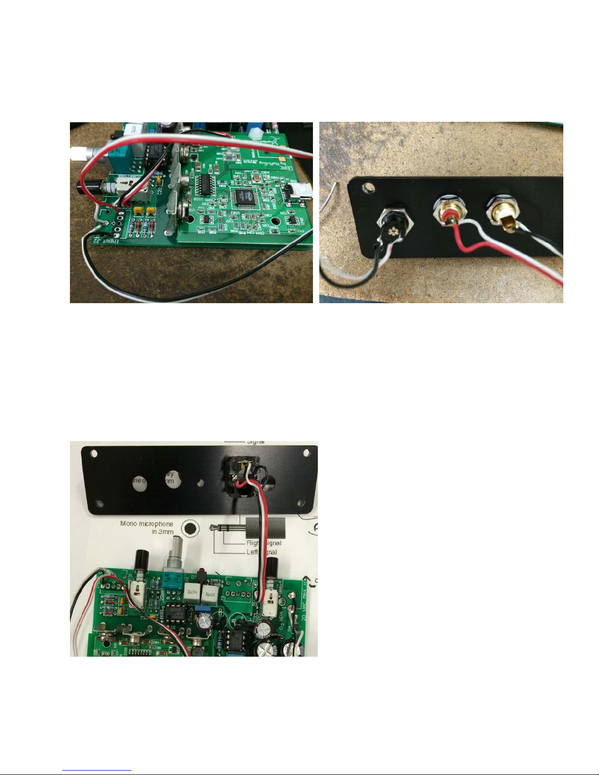
2. Bend leads of capacitors C8 and C9 and cover with heat shrink as shown in Figure 1.
3. Install C8 and C9, then complete remaining assembly of O2+ODAC. Remember to:
a. Omit J1, J2, and J3.
b. Cut input traces at bottom surface of J2, as normal in O2+ODAC assembly.
Figure 1: Install C8 and C9 as pictured. R10 and R11 shall be installed on opposite surface of PCB.
External Jack Assembly
1. Begin by mounting RCA jacks and AC power jack to rear plate.
2. Solder sufficient length of wire to AC power jack and each RCA jack.
3. Wire power jack:
Assembly Guide of Limited Edition O2+ODAC | Document Revision 1 Pg. 1 of 2
Page 2
a. Center pin of power jack is GROUND. Solder center pin (ground wire) to top, right hole of J1.
b. Sleeve pin of power jack is AC voltage. Solder sleeve pin to bottom hole of J1.
4. Wire RCA jacks:
a. White RCA jack is Left audio. Solder center pin to far Left pin of J2
b. Red RCA jack is Right audio. Solder center pin to far Right pin of J2
c. Outer sleeve of RCA jacks represent ground. Solder both wires to top, center pin of J2.
d. Solder enclosure ground wire to center pin of J2.
Figure 2: Wiring of RCA Jacks
5. Wire 1/4" headphone jack:
a. See Figure 3 for pinout of headphone jack (L = White, Red = Right, Black = Ground). Solder wires
of sufficient length to headphone jack to P2.
b. Solder headphone jack wires to P2. Pinout of P2 as viewed from top to bottom is:
i. GND
ii. GND
iii. LEFT
iv. RIGHT
Figure 3: Pinout of Headphone Jack. See step 5a
6. Make sure to orient headphone jack pins as shown. Jack will not fit into case otherwise!
7. Insert entire assembly into enclosure:
a. Attach screws of rear plate first
b. Attach front plate; remember to position enclosure ground wire around bottom right screw!
Assembly Guide of Limited Edition O2+ODAC | Document Revision 1 Pg. 2 of 2
 Loading...