

Page 1
ES SHUTTER FAN
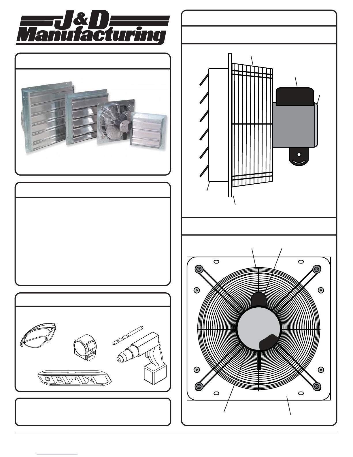
PRODUCT LEGEND
SIDE VIEW
Guard
Capacitor
Motor
WARRANTY
J&D Manufacturing warrants all products are free from defects in materials
and workmanship under normal use for the period of one year from date of
purchase. Our warranty does not cover normal or regular wear and tear.
J&D Manufacturing can repair or replace at our option, any product or part
of the product that is found to be defective. Our warranty applies to
materials only, and does not include return freight, delivery, loss or damage
to personal property, cost of removal or installation, any incidental or
consequential damages or labor. This warranty does not apply to products
which are misused, abused, altered, improperly installed or subject to
negligence. All warranties must be approved through our warranty
department. The original purchaser must present a copy of the invoice for
the defective product. One year is our standard warranty unless specified
on our literature or in the installation instructions or user manuals.
RECOMMENDED TOOLS FOR INSTALLATION (NOT PROVIDED)
Safety Glasses
Measuring Tape
Drill and Drill Bit
Shutter
Flange
BACK VIEW
Guard
Capacitor
Level
INSTALLATION HARDWARE IS NOT PROVIDED
Use appropriate fasteners and washers for your structure.
IS209-11I J&D Manufacturing • 6200 Hwy 12 • Eau Claire, WI 54701 • 1-800-998-2398 • www.jdmfg.com
Motor
Flange
Page 1 of 3
Page 2
INSTALLATION
POWERING UNIT
Please read over all instructions carefully before you
begin. If you have any questions please call your local
dealer, or contact J&D Manufacturing at 1-800-998-2398.
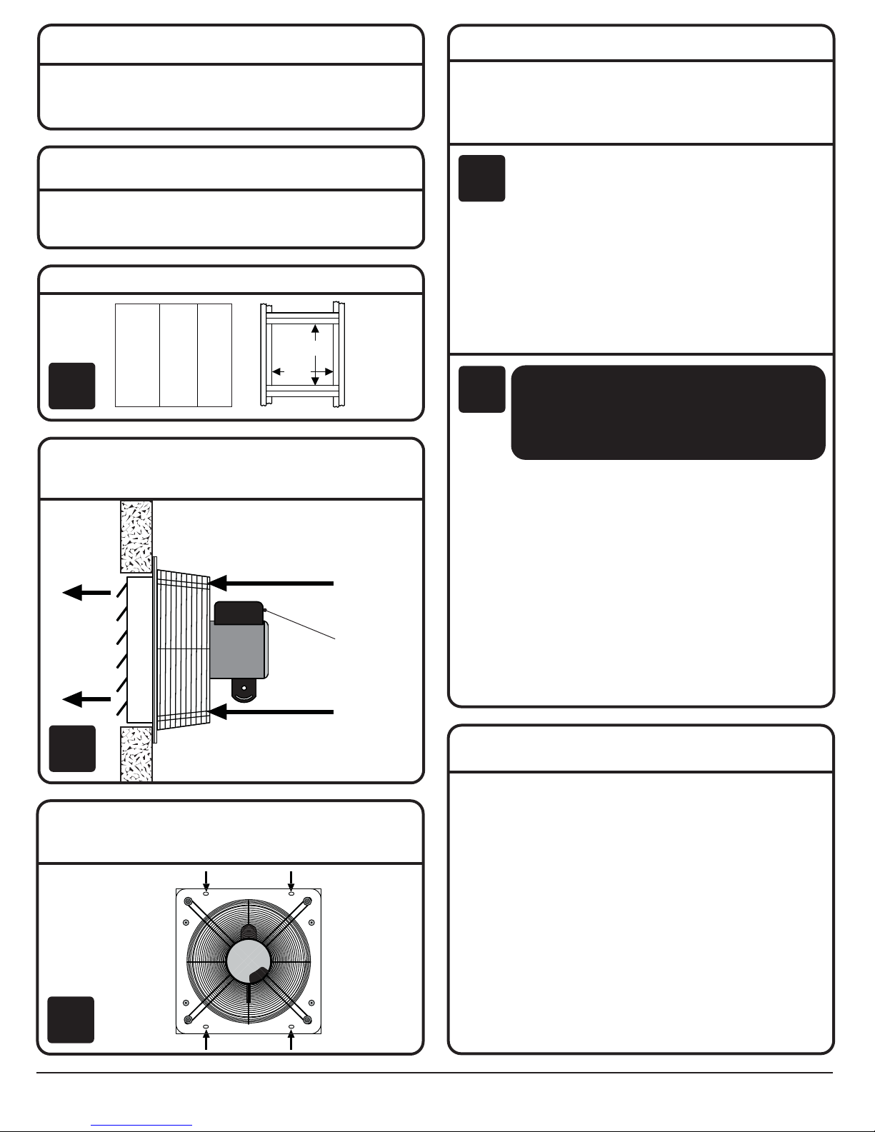
STANDARD INSTALLATION
This is the preferred method of installation. If the wall you are using is
exceptionally thick, or if you wish to have the shutter mounted to the
outside of your building, the ALTERNATE INSTALLATION may be used.
Construct a structurally sound rough opening for your fan.
Fan Size
___________________
___________________
___________________
___________________
___________________
___________________
1
Insert exhaust fan shutter into finished opening making sure that shutter
can move freely. Exhaust fan must be mounted with the motor inside of
structure, protected from the weather, and with capacitor on top as shown.
10”
12”
16”
20”
24”
30”
Height
10½”
12½”
16½”
20½”
24½”
30½”
Width
10½”
12½”
16½”
20½”
24½”
30½”
Height
Width
The ES Shutter fan is available with or without a pre-wired cord. If the
model you purchased includes an attached cord, proceed to step 4a for
instructions on powering your fan. If you purchased a model without a
cord, proceed to step 4b for wiring instructions.
• Plug cord into 115 AC grounded outlet that meets national,
regional and local codes.
4a
• Route electrical cord from motor to outlet with drip loop.
Drip loop will drain accumulated moisture away from the
motor and outlet.
• Only permit power to unit when shutter and guard is fully
installed to prevent injury.
Separate variable speed control is required to adjust fan speed.
Contact your dealer for more information.
ALL ELECTRICAL WORK SHOULD BE
4b
COMPLETED BY QUALIFIED PERSONNEL
AND MEET NATIONAL, REGIONAL
AND LOCAL CODES.
• Install manual disconnect switch inside building adjacent to
fan per national, regional,and local electrical codes.
Outside
Inside of structure
Direction
of airflow
Capacitor
Direction
of airflow
2
Using appropriate hardware (not provided) for your structure and the
weight of your exhaust fan, secure the fan to your structure using the (4)
pre-drilled holes on the flange.
• Route wire to motor with drip loop and secure. Drip loop will
drain accumulated moisture away from the motor.
• Configure internal wires to match supply voltage and wire
according to motor nameplate. Test to verify correct rotation.
• Only permit power to unit when shutter and guard is fully
installed to prevent injury.
Separate variable speed control is required to adjust fan speed.
Contact your dealer for more information.
MAINTENANCE INSTRUCTIONS
• Disconnect power before cleaning or maintaining your fan in order
to prevent serious injury or death.
• Service and repair of fan should only be completed by a qualified
technician.
• For maximum efficiency and fan life, keep the following free from
dirt and dust:
- blades
- housing
- shutters
- motor
- guard
3
IS209-11I
J&D Manufacturing • 6200 Hwy 12 • Eau Claire, WI 54701 • 1-800-998-2398 • www.jdmfg.com
• The totally enclosed air over motor has sealed ball bearings and
does not require additional lubrication.
Page 2 of 3
Page 3
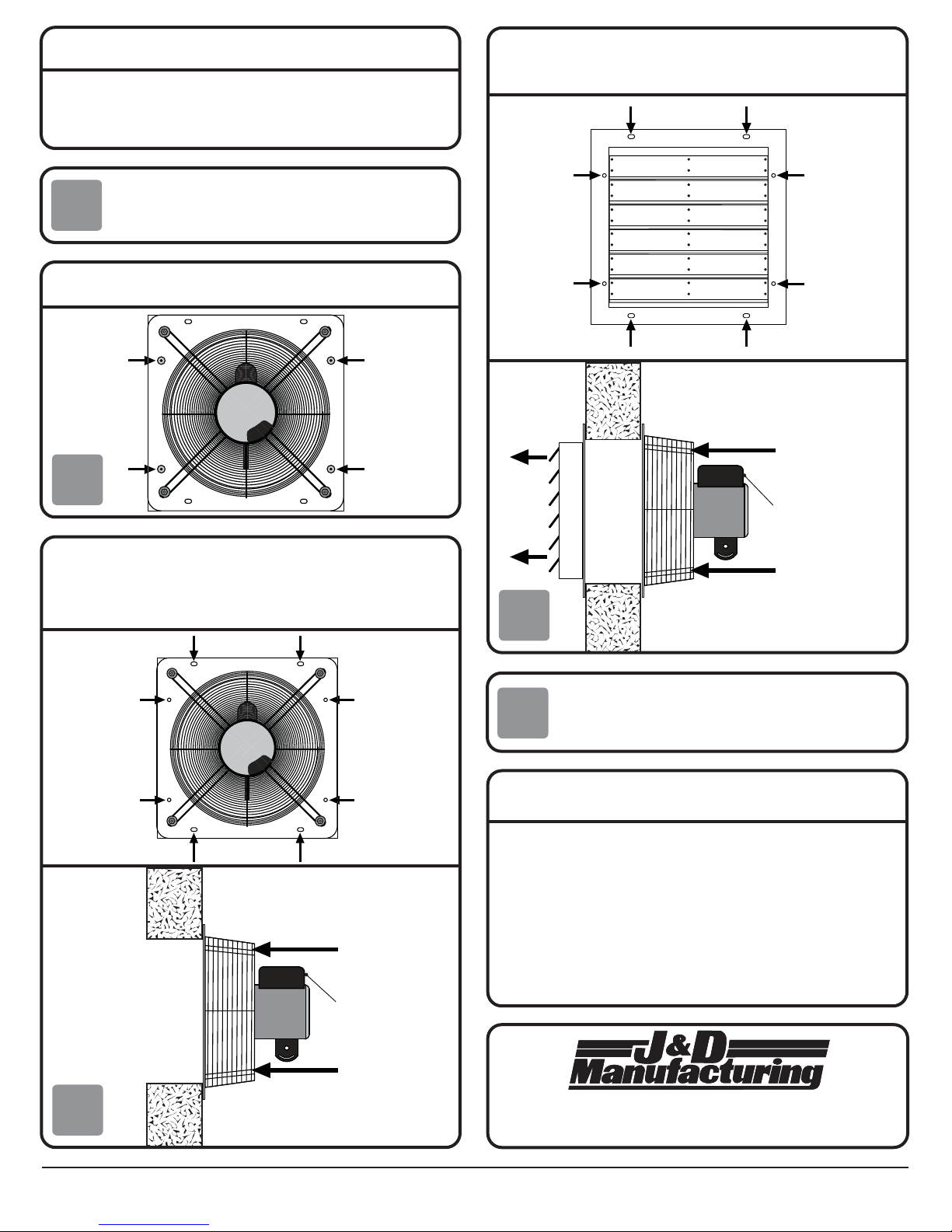
ALTERNATE INSTALLATION
The STANDARD INSTALLATION method is the preferred method. If the
wall you are using to mount your exhaust fan is exceptionally thick, or if
you wish to have the shutter mounted to the outside of your building, the
ALTERNATE INSTALLATION method may be used.
Construct a rough opening using dimensions listed in step 1
1
Separate the shutter from the assembled fan by drilling out the 4 rivets that
hold the shutter to the flange as shown below.
of STANDARD INSTALLATION
Using appropriate hardware (not provided) for your structure and the weight
of the shutter, secure the shutter to the outside of your structure using the
(8) pre-drilled holes on the flange. Louvers should open to the outside.
2
Using appropriate hardware (not provided) for your structure and the
weight of your exhaust fan, secure the fan to your structure using the (8)
pre-drilled holes on the flange. Exhaust fan must be mounted with the motor
inside of structure, protected from the weather, and with capacitor on top
as shown.
Outside
Inside of structure
Direction
of airflow
Capacitor
Outside
Inside of structure
Direction
of airflow
Capacitor
Direction
of airflow
4
Refer to step 4 of STANDARD INSTALLATION for instructions
on how to power your exhuast fan.
5
MAINTENANCE INSTRUCTIONS
• Disconnect power before cleaning or maintaining your fan in order
to prevent serious injury or death.
• Service and repair of fan should only be completed by a qualified
technician.
• For maximum efficiency and fan life, keep the following free from
dirt and dust: blades, housing, shutters, motor, and guard
• The totally enclosed air over motor has sealed ball bearings and
does not require additional lubrication.
Direction
of airflow
3
IS209-11I J&D Manufacturing • 6200 Hwy 12 • Eau Claire, WI 54701 • 1-800-998-2398 • www.jdmfg.com
6200 Hwy 12 • Eau Claire, WI 54701 • 1-800-998-2398
Visit our website at www.jdmfg.com
Page 3 of 3
 Loading...