

Page 1
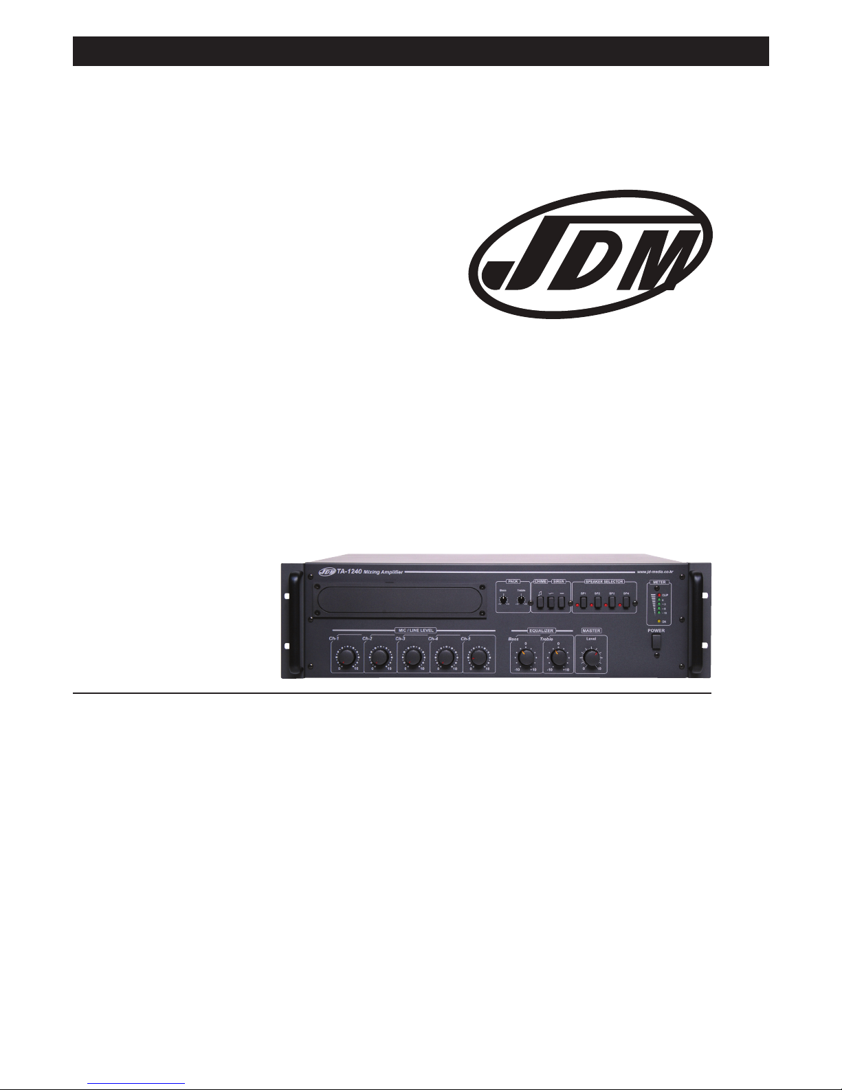
JDM®4 Zone Public Address Amplifier
1
Professional Four Zone
Desktop Mixing Amplifiers
A 4324 240W
Distributed by Altronic Distributors Pty. Ltd. Perth. Western Australia.
Phone: 1300 780 999 Fax: 1300 790 999
Internet: www.altronics.com.au
Operating Instructions
Revision 02/10/12
Page 2

Congratulations on purchasing this 4-Zone amplifier. It is housed
in a heavy duty 3RU rack mount cabinet and includes a host of
features. It provides an economical solution for smaller
installations including offices, workshops, smaller shopping
arcades, schools etc.
FEATURES
VERSATILE INPUTS
Channels 1 - 5 are combination XLR / 6.35mm balanced jack
sockets located on the rear panel. The XLR are microphone
level and the 6.35mm are line level (tip / ring / sleeve) inputs.
TELEPHONE INPUT
A telephone paging and music-on-hold input connection is
provided via spring terminals on the rear panel. Music sources
can be from a choice of optional modules that are installed into
the front panel slot.
SLOT FOR OPTIONAL INPUT MODULES
A slot in the front panel is provided in order to fit one of the
following optional modules: A 4344A (TP-100RDS) AM/FM RDS
Radio tuner module, A 4346 (CDR-100RDSU) CD/tuner module
with USB.
PRIORITY MUTING
MIC 1, CHIME and SIREN have priority over other inputs. The
muting level can be adjusted via a knob on rear panel.
REMOTE CHIME AND SIREN
This is operated by buttons on the front panel which play various
tones across the speakers. When the spring terminal on the rear
panel is shorted, CHIME is activated.
FOUR ZONES SPEAKER SELECTOR
Any combination of mono speakers (4 or 8ohm) can be selected
via front panel selector switches.
PRE OUT
A preamp output socket is provided enabling connection to extra
slave amplifiers or a signal processor.
24V EMERGENCY OPERATION
The unit will operate from 24V batteries for use in emergency
applications. Screw terminals provided on the rear.
AMP SECTION
• Automatic variable speed fan
• Over current protection
• Load short circuit protection
• Built-in low pass filter circuit
• Output level LED VU meter
SAFETY INSTRUCTIONS
• Please read these instructions before use. DO NOT switch on
the mains power until installation is complete.
• Locate the device away from any heat source, such as radiators, heating vents or in direct sunlight etc.
• DO NOT install in a confined space such as a cupboard or
book case. Ensure adequate ventilation of the unit.
• DO NOT expose to any form of liquid.
• DO NOT drop any foreign object or liquid inside the amplifier.
• This device should be serviced by a qualified service person.
IN THE BOX
• JD-Media PA Mixer Console
• Power Cord
• Rack Mounting Screws and Washers
• Operation Manual
OPTIONAL ACCESSORIES
• A 4346 CD Player / AM/FM Radio Tuner module
(CDR-100RDSU) with FM RDS / USB
• A 4344A– AM/FM Radio Tuner module
(TP-100RDS) with FM RDS
Note: The two modules listed above fit into the slot on the PA
mixer front panel. Each module includes the antenna
terminal, which fits into the PA amplifier rear panel.
• C 0377 - PUSH-TO-TALK Paging Mic which connects using
only a 3-Pin XLR Jack.
Note: These are the accessories which are supported for this
product in Australia, and which have descriptions within this
manual, as well as having their own manuals.
INSTALLATION
MOUNTING:
These amplifiers are designed to fit into standard 19” racking
space, and include the left and right mounting brackets in the
box.
COOLING:
When installing in a rack frame, never block the air vents on the
side, and make sure there is enough space (44mm) on either
side of the amplifier to allow air flow. Check the temperature inside the rack system to ensure it is not above 40 degrees Celsius. A cooling fan on the rear rack panel is recommended.
JDM®4 Zone Public Address Amplifier
2
Page 3
JDM®4 Zone Public Address Amplifier
3
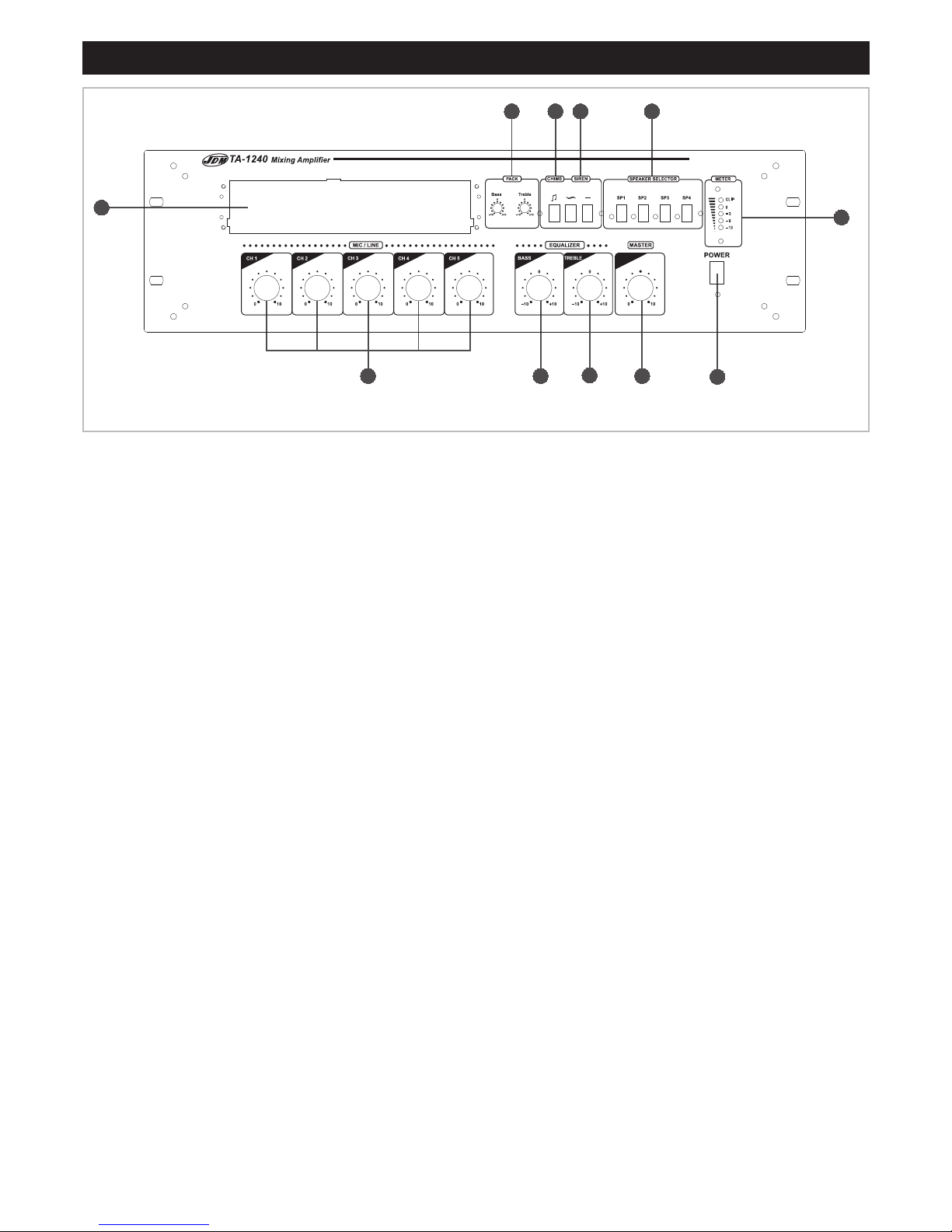
FRONT PANEL CONTROLS
1. POWER
Push switch to turn on. Power LED will illuminate when on.
2. METER
LEDs display the audio output level on the VU meter.
3. SPEAKER SELECTOR (SP1 – SP4)
These switches activate the amplifier speaker zones. Any
zones can be set to any output loading, but the total output
loading must not exceed the amplifiers maximum loading
specification.
4. SIREN
Pressing these switches will activate the siren tones. Two
sound patterns are offered, depending on which button is
pressed. One tone is continuous; the other tone varies in
pitch in a repeating cycle.
5. CHIME
Pressing this switch will activate the tone chime circuitry. This
is a four-tone ascending sound - ʻBONG BONG BONG
BONGʼ.
6. BLANK PANEL (PACK)
This is used for mounting the optional tuner (A4344A) or CD
player (A4346) modules or ʻPACKsʼ, which can be installed
into front panel slot, with the complementary antenna module
being installed on the rear.
7. MIC / LINE
These knobs (CH1 to CH5) adjust the volume levels of the
microphone or line inputs as selected by the rear panel switch
of CH 1 to CH 5.
8. BASS (EQUALISER)
Knob to adjust the low frequency sound to the MASTER
volume output.
9. TREBLE (EQUALISER)
Knob to adjust the high frequency sound to the MASTER
volume output.
10. MASTER
This knob is used for adjusting the volume of the output audio
mixed from all five sources.
11. PACK (BASS & TREBLE)
These BASS and TREBLE knobs control the bass and treble
signals of the optional tuner or CD player (also called
ʻPACKʼ), but only when either is installed in the front slot of
the amplifier.
7 8 10
34511
1
2
6
ON
www.jd-media.co.kr
9
Fig 1: Front Panel Controls
Page 4

JDM®4 Zone Public Address Amplifier
REAR PANEL CONTROLS
1. AC POWER INPUT.
2. FUSE HOLDER
This fuse holder contains the power fuse (T 4AL 250V).
Ensure it is replaced with same type of fuse when it blows. If
it continually blows, there may be an amplifier fault. Please
contact a qualified service technician.
3. DC POWER 24V/20A
This terminal is for connecting the 24V battery for emergency
operations.
WARNING: Ensure the correct battery polarity to prevent
damage to the amplifier.
4. SPEAKER ZONES
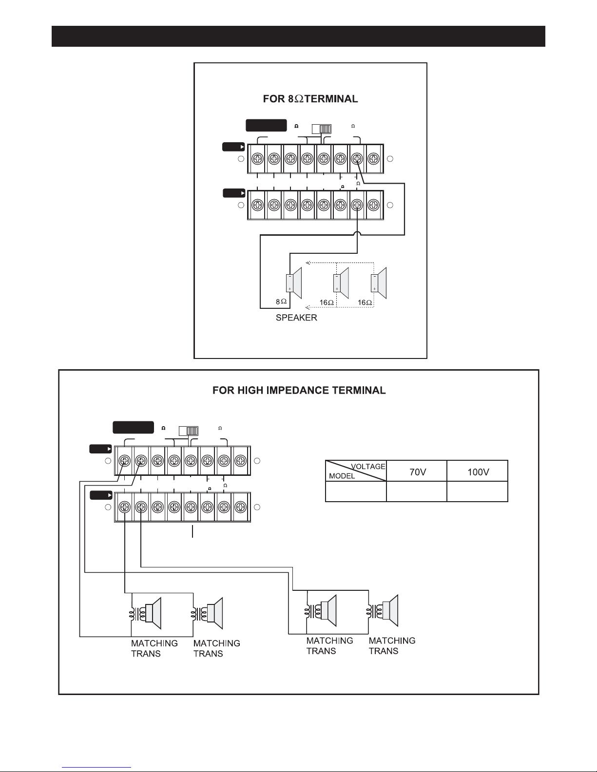
Refer to the speaker connection terminals figures 3a and 3b.
WARNING:
• Do not connect speakers to more than one terminal type.
That is, connect only to the four ohm, or only to the eight
ohm, or only to the high impedance terminals.
• Do not connect speakers to the four ohm or eight ohm
terminals where the power rating of the speakers is less
than the power rating of the amplifier.
• For the high impedance terminals do not connect
speakers where the total impedance is less than the rated
impedance (see Fig. 3b). Failure to follow this may result
in damage to the amplifier and / or speakers.
5. MESSAGE PRIORITY
Not Supported in Australia
6. ANTENNA
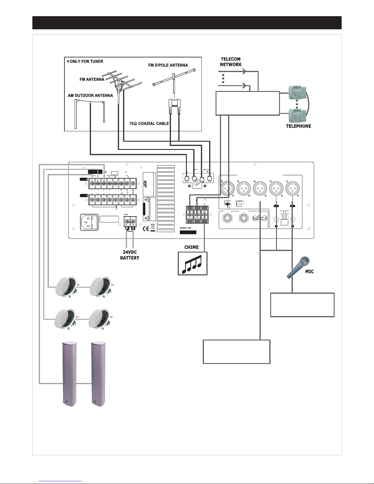
Only fitted when either a tuner (A4344A) or CD (A4346)
module is installed. See Fig 4 for wiring.
NOTE: The picture of the amplifierʼs rear panel above shows
the antenna terminal in place. This section of the amplifierʼs
rear panel is blocked by a removable ʻknock-outʼ section of
metal plate, which needs to be punched out and removed in
order for the antenna terminal to be screwed in place.
7. MIC(XLR) / LINE(PHONE) INPUTS
These are for microphone or line inputs CH1 to CH5.
Microphone input sensitivity and impedance is 3mV/600 ohm.
Line input is 300mV/50k ohms.
The XLR / Phone jack combined sockets have been designed
for Mic or Line inputs without the need for switches.
Note: Pin 1 on the XLR and the Sleeve on the phone jack are
grounded, as per the diagrams on the rear panel.
8. MUTE
These knobs adjust the muting levels of inputs CH1 and CH2.
9. PRIORITY / (PHANTOM POWER)
Two of the four dip switches provide CH1 and CH2 with
phantom power for condenser microphones. The other two
switches activate priority muting for the same two channels.
IMPORTANT: When using phantom power, turn the CH1 and
CH2 volume control knobs on the front panel anti-clockwise
to decrease the level, so as to avoid damaging the speakers.
10. PRE OUT
This jack is for connecting line level output signal to external
amplifier or a signal processor such as an equalizer.
11. AMP IN
This input is for a direct signal from external equipment (+4dB
level). It is controlled by the MASTER volume knob on the
front panel.
12. REMOTE CHIME terminal
When these terminals are shorted, the chime is activated.
13. REMOTE SIREN terminal
When these terminals are shorted, the chime is activated.
14. TEL IN
These terminals are for connection to a telephone system for
paging. Use an Austel approved line isolation unit with this
input.
Note: When paging, all other input signals except AMP IN are
muted.
15. HIGH IMPEDANCE SWITCH
This switch is for selecting the impedance of the high
impedance speaker terminals (70V or 100V).
1 2 3 9
8
7
14 13 12 11 10
654
BALANCED OUTPUT
(20 ) 70V 100V(42 )
MESSAGE
E/M CON
HIGH IMPEDANCE
DIRECT
OUTPUT
SPK ZONES
CLASS 1 WIRING
FUSE RATING
T4AL 250V
CLASS 2 WIRING
8
LOW
25V
HIGH
1
2
34
(2.6 )
70V
100V
( )
HOT
COLD
CAUTION:
TO REDUCE THE
RISK OF FIRE REPLACE ONLY
WITH SAME TYPE FUSE.
DC POWER
24V/20A
MODEL.: T
A-1240
MADE IN KOREA
CAUTION
RISK OF ELECTRIC SHOCK
DO NOT OPEN
WARNIN G:
T
O REDUCE THE RISK OF FIRE
OR ELECTRIC SHOCK DON'T EXPOSE THIS
EQUIPMENT TO RAIN OR MOISTURE.
MIXING AMPLIFIER
300
AM GND
FM 75
AMP IN
PRE OUT
MASTER
CLASS 2
MIC
S (GND)
T ( )
R ( )
SRT
LINE
G
1
2
3
5
4
3
2
CHIME
REMOTE
SIRENTEL IN
1
MIC(XLR) / LINE(PHONE) INPUTS
30
20
10
50
1
2
30
20
10
50
P.H P.H
LINE MIC
LINE
MIC
H.A
H.A
RMS 240W
PRIORITYPRIORITY
AC230~50Hz 625W
JD-MEDIA CO.,LTD.
15
Fig 2: Rear Panel Layout
4
Page 5
JDM®4 Zone Public Address Amplifier
A 4324 20Ω
41Ω
BALANCED OUTPUT
(20 ) 70V 100V(42 )
HIGH IMPEDANCE
DIRECT
OUTPUT
SPK ZONES
8
LOW
25V
HIGH
1
2
34
(2.6 )
70V
100V
( )
HOT
COLD
RMS 240W
BALANCED OUTPUT
(20 ) 70V 100V(42 )
HIGH IMPEDANCE
DIRECT
OUTPUT
SPK ZONES
8
LOW
25V
HIGH
1
2
34
(2.6 )
70V
100V
( )
HOT
COLD
RMS 240W
+VE
Terminal
Common
Terminal
Common
Terminal
Be sure that total impedance is not
less than rated impedance. This
includes switched speaker zones
& direct 70/100V is a permanent
output connection, irrespective of
speaker zone switching.
These terminals can be used for speakers
to bypass the speaker zone switching.
Fig 3a & 3b: Connect speakers as per these diagrams. Ensure power is off before connecting or disconnecting speakers.
Fig 3a
Fig 3b
5
Page 6
JDM®4 Zone Public Address Amplifier
BALANCED OUTPUT
(20 ) 70V 100V(42 )
MESSAGE
E/M CON
HIGH IMPEDANCE
DIRECT
OUTPUT
SPK ZONES
CLASS 1 WIRING
FUSE RATING
T4AL 250V
CLASS 2 WIRING
8
LOW
25V
HIGH
1
234
(2.6 )
70V
100V
( )
HOT
COLD
CAUTION:
TO REDUCE THE
RISK OF FIRE REPLACE ONLY
WITH SAME TYPE FUSE.
DC POWER
24V/20A
MODEL.: T
A-1240
MADE IN KOREA
CAUTION
RISK OF ELECTRIC SHOCK
DO NOT OPEN
WARNING:
TO REDUCE THE RISK OF FIRE
OR ELECTRIC SHOCK DON'T EXPOSE THIS
EQUIPMENT TO RAIN OR MOISTURE.
MIXING
AMPLIFIER
300
AM GND
FM 75
AMP IN
PRE OUT
MASTER
CLASS 2
MIC
S (GND)
T ( )
R ( )
SRT
LINE
G
1
2
3
5
4
3
2
CHIME
REMOTE
SIRENTEL IN
1
MIC(XLR) / LINE(PHONE) INPUTS
30
20
10
50
1
2
30
20
10
50
P.H P.H
LINE MIC
LINE
MIC
H.A
H.A
RMS 240W
PRIORITYPRIORITY
AC230~50Hz 625W
JD-MEDIA CO .,L TD .
TELEPHONE
PABX UNIT
TELEPHONE PAGING INPUT
MUSIC ON HOLD
SPEAKERS
SPEAKERS
SPEAKERS
BALANCED
INPUT SOURCE
AUX INPUT SOURCE
EG: CD PLAYER
Fig 4: Connection Guide
6
Page 7
JDM®4 Zone Public Address Amplifier
7
SPECIFICATIONS
A 4324 power: ...................................................... 240 watts RMS
Distortion: .............................................................. < 1% @ 1kHz
Signal to noise ratio .................................... Line: >70dB Mic: >60dB
Frequency response .......................................... 80Hz - 15kHz, ±3dB
Mic input sensitivity: .............................................. 3mV balanced
Line inputs sensitivity: ...................................................... 300mV
Phono input sensitivity: ...................................................... 2.4mV
Telephone input ................................................................ 245mV
Bass: .................................................................. ±10dB @ 100Hz
Treble: ................................................................ ±10dB @ 10kHz
Standby current (DC operation): ........................................ 0.51A
Fuse ..............................................T4AL 4A M205 4 x 20mm type
Power supply: .............................................. 240V AC or 24V DC
Dimensions: ...................................... ≈483W x 350D x 133H mm
A 4324 weight: .................................................................. 18.7kg
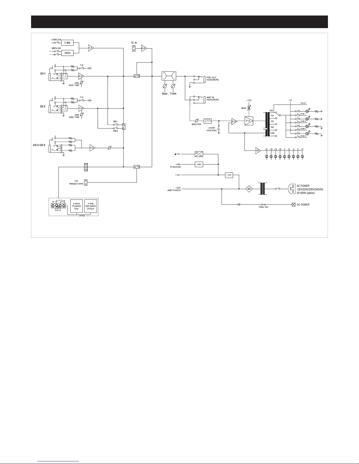
Fig 5: Block circuit diagram.
Page 8

Altronic Distributors warrants this product for two years from the date of purchase from Altronics or its resellers to the consumer. If this
item is part of an installation or another product, please contact the installer or supplier for your warranty.
During the warranty period, we undertake to repair or replace your product at no charge if found to be defective due to a manufacturing
fault. The warranty excludes damage by misuse or incorrect installation (i.e. failure to install and operate device according to
specifications in the supplied instruction manual), neglect, shipping accident, or no fault found, nor by use in a way or manner not
intended by the supplier.
For repair or service please contact your PLACE OF PURCHASE.
If this item was purchased directly from Altronics please make a warranty claim by:
1. FOR MAIL ORDER CUSTOMERS (includes school and trade orders),
a) Ringing us on 1300 797 007 and quoting your tax invoice number.
b) Upon contacting Altronics, we will issue an R.A. (Return Authorisation).
As Altronics have a number of service agents throughout Australia,
a copy of the R.A. will be emailed, faxed or mailed to you with full instructions
of how and where to send the goods. The freight for shipping goods back to
Altronics for all repairs is at the customers expense.
c) A copy of the R.A. form, (or at the very minimum, the R.A. number) must
accompany the goods to effect the repair.
d) Altronics will pay the return freight to the customer where the warranty claim
has been accepted.
e) Please quote the R.A. number in any correspondence to us.
2. FOR OVER THE COUNTER PURCHASES to make a warranty claim,
please return the goods to us in any of our stores, with a copy of your
proof of purchase (tax invoice).
a) Upon leaving the goods at one of our stores, an R.A. number
will be issued to you.
b) Once repaired, you will be contacted, advising that the goods are ready to be
collected from the store.
It is at Altronics discretion as to whether the goods will be repaired or replaced (whilst under warranty); and as to whether identical
goods will be used to replace the item due to changes of models / products.
Note: Under no circumstances should you attempt to repair the device yourself or via a non-authorised Altronics service
centre, as this will invalidate the warranty!
Our goods come with guarantees that cannot be excluded under the Australian Consumer Law. You are entitled to a replacement or
refund for a major failure and for compensation for any other reasonably foreseeable loss or damage. You are also entitled to have the
goods repaired or replaced if the goods fail to be of acceptable quality and the failure does not amount to a major failure.
JDM®4 Zone Public Address Amplifier
8
NOT FIELD SERVICEABLE.
Distributed by Altronic Distributors Pty. Ltd.
Phone: 1300 780 999 Fax: 1300 790 999
www.altronics.com.au
 Loading...