

Page 1
1
Page 2

2
Content
Preface…………………………………………………………………………………………(2)
I Summary………………………………………………………………………………………(6)
II Safety instruction………………………………………………………………………(9)
III Installation……………………………………………………………………………(12)
IV Unwind--Feeder……………………………………………………………………………(16)
V Offset printing unit………………………………………………………………………(21)
VI Offset printing water and ink uints…………………………………………………(25)
VII Cold foil unit …………………………………………………………………………(52)
VIII Die cutting unit………………………………………………………………………(55)
IX Matrix unit…………………………………………………………………………………(65)
X Rewind unit……………………………………………………………………………………(69)
XI Lubrication system…………………………………………………………………………(74)
XII Maintenance……………………………………………………………………………… (79)
Annex I Manual for mounting plate
Page 3

3
Preface
This manual is an operation manual about Jiangxi Zhongjing Group JDL-420 multi-
function web printing machine. The control process of accessories and third-party
equipments is only for reference, such as electrical control, sample table, alcohol
box, bending plate machine, laminate machine, UV and water cooling equipment.
【Notes on special security】
For your safety and the protection of the machine, please be sure to read the manual
and all the accompanying information on other related equipments before installing,
running, maintaining and checking. Make sure the operator in charge of the operation
reads and understands the instructions.
Please be familiar with related knowledge, safety information and notes about all
equipments before use.
The machine can only be operated by people who can meet the intellectual and
physical requirements of machine operation.
1、 Notes on intallation
(1)The installation and commissioning of the machine must be carried out by our
own specialists or by our authorized specialists.
(2)The operating environment has an important influence on the quality of print
samples. So a good operating environment can reduce the occurrence of failures. The
installation and use environment shall meet the requirements of the production of
specialized equipment. ( For details, please refer to the requirements in Chapter
III, "Installation and Use Environment of Machine".)
(3)The requirements of lifting and level when installation must be done strictly in
accordance with the requirements of (Chapter III Installation)
(4)This model uses alcohol plating, alcohol, printing ink, printing paper, grease
and other flammable goods. The printing workshop requires good fire prevention
measures and no fireworks.
2、 Notes on electrical appliances
(1)For details on electrical safety of machines, please refer to the "Manual of
Electrical Operation".
(2)Touching exposed high-voltage lines can be extremely damaging with electric
shocks.
Page 4

4
3、 Notes on starting, operation, maintenance
(1)The machine must be used by operators who are specially trained and specialized
in rotating trademark printing machines.
(2)All operations and maintenance on the central console, machinery, electrical
appliances and third-party equipments must only be performed by persons who are
fully familiar with the operation, maintenance and repair of the machine and who are
aware of the danger.
(3)Safety precautions relating to other related equipments, accessories and third-
party equipments, for details in the annexes, the safety instructions about other
related equipments, and third-party equipments and all information attached to other
related equipments.
4、The machine is ready to run when the bell is ringing. All manual operations
must be stopped and withdrawn from the dangerous position immediately.
5、Notes on disusing
When the machine is discarded, please treat it as industrial waste.
【USE】
1、Material
⑴、JDL-420 model series multi-function web printing machines are suitable for
printing adhesive, coated paper, offset paper, cardboard, plastic film and so on.
If there are any special materials, it must be confirmed by us before printing
⑵、Paper size and thickness should not exceed or be lower than the values
indicated in the manual. The paper stiffness must be within the range of general
printing materials. Printing ink should be commercial rotation UV ink, light oil
or glue.
2、Technical conditions without defects
⑴、Machines, accessories and third-party equipments can only be operated without
defect technical conditions. All protective devices on the machine and all safety
devices in the printing workshop must be complete and functional.
3、Modifications are not allowed.
It is prohibited to modify, add or refurbish the machine without the permission of
the manufacturer of the machine. For example, replacing software, installing new
features, changing machine parameters and electronic control are not allowed.
4、Comply with operating instructions
Page 5

5
⑴、The use includes complying with operation and maintenance instructions provided
by the manufacturer, which also applies to external parts and third-party equipments.
⑵、All operations on central consoles, machines and third-party equipments can only
be performed by personnel who are fully familiar with the operation, maintenance and
repair of the machine and who are aware of the danger.
⑶、The machine is only available to those in charge who are specially trained to
specialize in web printing. Responsibility and distribution of tasks must be clear
and supervised.
5、Abide by the law
Comply with the laws and regulations of the country concerning labor safety,
environmental protection and use of equipment. Printed products, publications, and
etc. shall comply with the relevant provisions of the country's intellectual
property protection law, public publications, and etc.
6、Irresponsible matters
For your safety and the protection of the machine, please read the instructions in
details before using the machine. During use, you should operate the machine
strictly according to instructions of the Manual, especially pay more attention to
the safety notes.
Any use that is not mentioned here or is used out of the above is not an expected
usage. For example, the modification,joint and the idling of the installed machine
affect the normal function of the machine, or the unrestricted use, or the skipping
of the safety equipment, or failure to use the machine in accordance with the
parameters specified in the instruction manual, The operation of machines that do
not comply with the requirements of the instructions for use is within the scope of
unexpected use.
We do not allow any claims for any unexpected usage, personal injury, or damage to
the machine.
7、Printing output
The reference to 150 m/min refers to technically possible capabilities, but it is
not actually achieved in daily production, depending on the parameters beyond our
control. For example, the operator's proficiency, printing materials, printing
plates, ink and preparation of the printing environment, etc..
Page 6
6
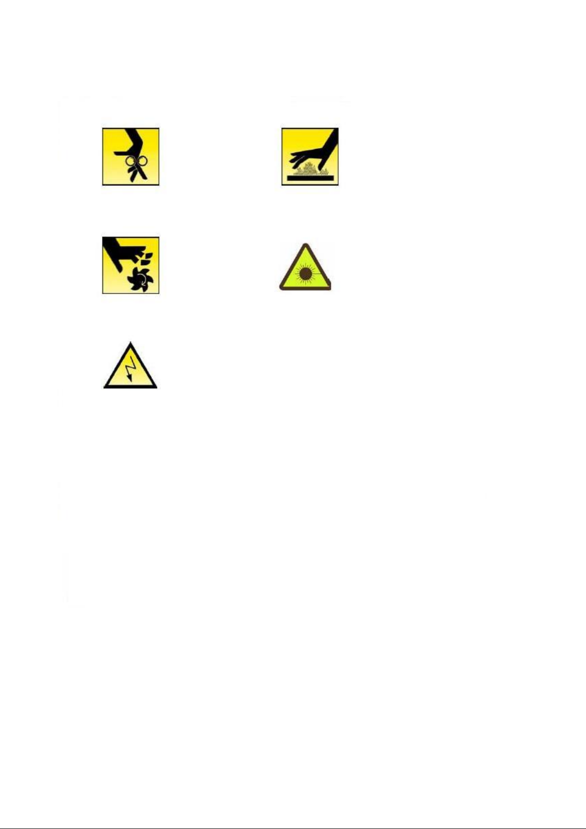
Warning sign
Watch your
fingers
High surface
temperature
Rotating
sharp
objects
Don’t look
directly
Dangerous
Electricity
Page 7

7
I Summary
Printing speed
150m/min
Printing units
4-8 units
Max.Pinting repetition length
635mm
Min. Pinting repetition length
469.9mm
Max.web width
420mm
Min.web width
210mm(paper) 315mm(film)
Max.printing width
410mm
Web thickness
0.06~0.35mm
Max.unwinding diameter
1000mm/350Kg
Max.rewinding diameter
1000mm/350Kg
Max. unwinding and rewinding diameter of
cold foil
600mm/40Kg
Offset plate thickness
0.3mm
Blanket thickness
1.95mm
Flexo plate thickness
1.14mm
Thickness of double sided adhesive
0.5mm
Margin
3mm
Total power
See machine installation diagram
Voltage
Three phases, 380V±10%
Control voltage
220V
Frequency
50Hz
一、Use
JDL-420 model series continuous PS plate composite trademark printing presses are
suitable for printing adhesive, coated paper, cardboard, aluminum foil and
plastic film. The machines adopt unit type modular combination, which can be used
in 4-8 color printing. Each unit can be chosen any printing methods in offset,
flexo, screen, and cold foil. They adopt shaftless drive configuration, automatic
registration system and pre-registration system, in order to ensure accurate
registration with high speed (150m/min) and low rate of spoiled products. They
are ideal machines to print high-grade products, daily chemical products, wine
labels, medicine labels, packaging boxes, adhesive labels and so on.
二、Specifications
Page 8

8
Main machine size(length*width*height)
13000X2220X2280
Net weight
Offset printing units
2270Kg/unit
Unwinding unit
1400Kg
Die cutting and matrix units
1350Kg
Rewinding unit
920Kg
Cases size
Offset printing units
2380X1850X1900
Unwinding unit
2585X2370X1900
Die cutting and matrix units
2380X1850X2300
Rewinding unit
2380X1850X1300
Control table
1800X900X2000
Main power cabinet
1200X600X2200(2 pcs)
UV main power cabinet
850X600X2000(2 pcs)
Sticker machine
1200X700X1650
Bending machine
1600X1000X1250
Air compressor
1600X650X1200
Alcohol tank
650X550X1100
三、Features
1. Combination printing and unique sharing platform technology. It can be combined
with offset printing, flexo printing, screen printing, cold foil, super glazing,
laminating and other printing processes. Various printing processes can be combined
arbitrarily according to the requirements of different printing products. It is
suitable for various types of label printing.
2. Large printing area is 410 X 635mm and maximum printing perimeter can be up to
635mm. The maximum speed can reach 150m/min. Whether it is a large quantity order or
big label job, you can handle it easily.
3. It can print many kinds of printing materials, such as paper, plastic film, metal
foil. The thickness is from 0.06mm (film) to 0.35mm (cardboard).
4. Shaftless drive: The whole machine adopts the servo drive technology from
unwinding to printing, die-cutting to rewinding. The servo drive is been applied to
unwinding and rewinding units, so that the printing tension can be controlled more
accurately. The printing tension adopts closed loop control system, which is driven
Page 9

9
by servo motors separately. Offset plate rollers, blanket rollers, impression
rollers, ink and water are all been driven by the servo motors, which is stable
operation and high precision. It can reduce ink bar without gears.
5. Automatic registration system, especially for more than one unit, registration
system is better than others. Its registration adjustment precision is to 0.01mm.
The axial and radial registration can be adjusted automatically and simultaneously.
The registration can be in the right place within two printing circumference.
6. Preset registration function: to install the plate roller before printing, then
press the start button, the plate roller will automatically look for the zero
position for registration. Registration requirements can be achieved without manual
adjustment. It improves efficiency, saves a lot of materials and labor costs.
7. Portable sleeve technology. The plate and blanket sleeve of magnesium aluminum
alloy can change the printing format and type easily. The operation is simple and
the maintenance cost is low.
8. It can adjust the parameters of the machine at any time through a digital handle,
store and call datum of each production working orders in printing management center.
The datum contain the optimal state of the machine during production. These datum
will be used to set the machine state when the order is stored and called. In
addition to boot, shutdown, speed control, counting and other basic functions, it
can achieve all the control of the printing machine, and perform work storage and
call, offset water and ink can be controlled automatically, registration control and
real-time detection.
Page 10

10
II Safety instruction
一、Safety instruction
1. The printing press shall be operated and used by trained professionals. The
installation and commissioning of the machine must be carried out by our own
specialists or by our authorized specialists.
2. For your safety and the protection of the machine, please read the instructions
in details before using the machine. During use, you should operate the machine
strictly according to instructions of the manual, especially pay more attention to
the safety notes.
3. Our company shall not accept any claims for any personal injury or damage caused
by any use of the machine not in accordance with the parameters specified in the
instructions and for the operation of the machine not in accordance with the
provisions of the instructions.
4. The ignition point of the printing ink must be higher than 21 °C. Thickness of
substrate: 100-200 μ m
二、Management standard
1. Please keep the manual next to the machine so that you can read it at any time
2. In addition to what is mentioned in the operation manual, the operation must
comply with the regulations on accident prevention and environmental protection
stipulated by local laws at the same time.
3. For safety reasons, staffs are required to wear clean work clothes. Sleeves and
chest buttons must be buttoned up, not open chest. Ladies must wear hair caps to
enter the workshop.If ladies do not wear hair caps, they are not be allowed to
operate the machine. It is strictly forbidden to use the machine in shoes, high
heels, earplugs, long skirts, long hair, and other violations of the relevant
operating rules
4. This model uses alcoholic system. Alcohol, printing ink, printing paper and
grease belongs to flammable items. If the machine is placed in a closed space, pay
attention to the flammable gas concentration and ensure air exchange timely to
avoid spontaneous combustion or explosion. The printing workshop must make good
fire prevention measures and strictly prohibit fireworks.
5. Compliance with safety and warning instructions on the machine.
Page 11

11
6. Modification, addition or replacement of any devices that may affect safety is
forbidden.
7. Spareparts must be purchased in accordance with the technical requirements
specified by the manufacturer or authorized manufacturers
8. Software programs of control systems are prohibited to change. If changing, our
company shall terminate any liabilities immediately.
9. It is forbidden to place flammable or explosive or solvent coated rags next to
UV lamps to avoid explosion.
10. UV lamps produce harmful rays that damage the skin and eyes of the human body.
So it is prohibited to open the safety cover during the operation of the machine.
11. UV lamps produce ozone, so ventilation systems must be installed. The maximum
amount of indoor ozone is not allowed to exceed 0.1 ppm.
三、Security notes
1. Normalize operations to avoid any breach of safety regulations
2. The necessary precautions must be taken to use the machine in safe and secure
conditions.
3. The machine can only be operated if the safety protection device is working
properly. Such as: removable safety devices, emergency stop devices, soundproofing
and exhaust systems.
4. The machine must be checked for damage at each shift, and any changes must be
reported to the company in time. If necessary, it must be shut down and locked
immediately.
5. You must check the safety of the device at least once before starting.
6. The yellow device can only be unloaded when the device is replaced. After the
device is removed, the device must be reinstalled. Power must be turned off before
this operation can be performed.
7. The temperature of the plant in which the machine is located must not exceed 36º
C. High temperature will affect the life of the electrical equipment and increase
the surface temperature of the substrate.
8. UV lights and drying equipment must be turned off before cleaning equipment.
9. Only after the power is turned off, the safety cover can be removed.
10. Only personnel with relevant electrical qualifications are allowed to open the
cabinet door.
Page 12

12
11.The filter of the ventilation system must be kept clean. Otherwise, the function
of the system will be reduced, and the air flow to the heating element will be
reduced, which may cause overheating or fire.
12.The temperature of UV lamp tube and oven cover shell is high, watch out for
scald.
13.Only experienced personnel are allowed to adjust, maintain, inspect equipment
and replace parts.
14.When maintaining and repairing the equipment, be sure to turn off the power and
lock the main switch to prevent inadvertent turning on the power.
15.After the machine is overhauled, maintained or repaired, the safety cover must
be reinstalled and checked immediately.
16.In the case of downtime during the printing process(for example, due to the
breaking of the tape or high temperature alarm, etc.), the UV lamp must be turned
off to prevent the tape from overheating and burning.
Page 13

13
III Installation
一、Working environment, transportation and storage requirements
The operating environment of the machine has an important influence on the quality
of printed materials. A good operating environment can reduce the occurrence of
faults. The installation and use environment of the machine shall conform to the
requirements of the production of web printing machine.
1.In the process of transportation and storage takes safety measures, such as dust-
proof, earthquake-proof, collision-proof, fire-proof, corrosion-proof, Rust-proof
and other measures.
2.Workshop ground should take moisture-proof and shock-proof measures. Design of
doors and windows should be moisture-proof, or the use of wind curtains to block the
flow of outside air into the workshop to avoid the impact on the balance of ink.
3.When the printing press is installed, it should take safety measures, such as
dust-proof, earthquake-proof, fire-proof, heat, ventilation, lighting,
dehumidification, noise reduction and other measures. Room air should not include
acids, salts and corrosive gases. Best relative humidity 55 % -65 %, no condensate
water. The installation of the machine is conducive to the arrangement between the
various processes and the logistics direction is reasonable.
4.The installation temperature of the machine is not more than 37 °C, the constant
ambient temperature is conducive to the stability of the printing quality, the
optimal temperature range of 20 ± 2 °C.
5.The min. installation distance between electric cabinet and wall is 0.8 meters,so
as to ensure heat dissipation, ventilation and easy maintenance.
6.Power voltage is 380V. Fluctuation is less than 10 %. Frequency is 50Hz. For areas
surrounded by large electrical equipment, it should install automatic voltage
control power with 100KW. This machine uses communication methods to connect and
control various units. It is necessary to prevent strong magnetic interference
around it, such as high-voltage lines, microwave transmission stations. If necessary,
the factory building must take metal network shielding measures.
二、Installation
1、Installation preparation
Build the foundation according to drawings (there are some differences because of
different options). Before pouring concrete, please pre-bury the cable pipe or make
a good line groove for laying the wire.
Page 14

14
If the machine is installed upstairs, the bearing capacity of the building must not
be less than 2 T/m².The machine seat must pass through a load-bearing beam. The
weight of the load-bearing beam is calculated by multiplying the weight of the
machine by 1.2 times (load coefficient).
For plant foundations filled with soft soil areas or original farmlands / lakes, the
thickness of the foundation must be increased by 500MM to prevent irregular
settlement and affect the accuracy and life of the machine.
2、Installation
(1) Connect each module unit according to the schematic diagram of the machine.
(2) Calibrate machine level and adjust support bolts on machine base to find machine
level.
Gradienter specification: 0.02/1000
Calibration Level Requirements:
Longitudinal level (in the direction of the length of the machine) is not greater
than: 0.08/1000
Transverse level is not greater than 0.04/1000
The degree of parallelism between the leveling units is not greater than 0.03.
【Notes】:
①、In order to increase the stability of the machine, the closer the seat is to the
ground, the better.
②、After installing and putting into operation about 70-80 shifts, the level of the
machine should be re-adjusted to check the changes after the foundation is pressed.
(3)、Fixed expansion screws in offset printing units.
(4)、Connect UV, Refrigerator,alcohol tank and control table.
(5)、Connect ventilation.
(6)、Connect lubricating tubing.
(7)、Clean rust resistant oil.
(8)、Connect electrical wires (for details, please refer to the "Electrical Section
of the Manual")
(9)、Test run (see test run before installation and operation).
三、Test run
1.Long-distance transportation may lead to loosening of certain wiring screws and
lead to poor contact resulting in control failure. The user is required to re-check
Page 15

15
and tighten the terminal screws of all components and terminal rows before turning
on the power.
2.Before test run, all parts of the machine shall be fully inspected for connectors,
fasteners, fastening screws, tapers, opening pins, Stoppers, etc., to prevent
accidents caused by loose or falling parts that may occur during transportation.
3.According to the lubrication instructions, add the necessary lubricant to the fuel
tank and oil cup, and use the oil gun to fill each artificial injection point.
4.Check if the power feed phase sequence is correct or not.
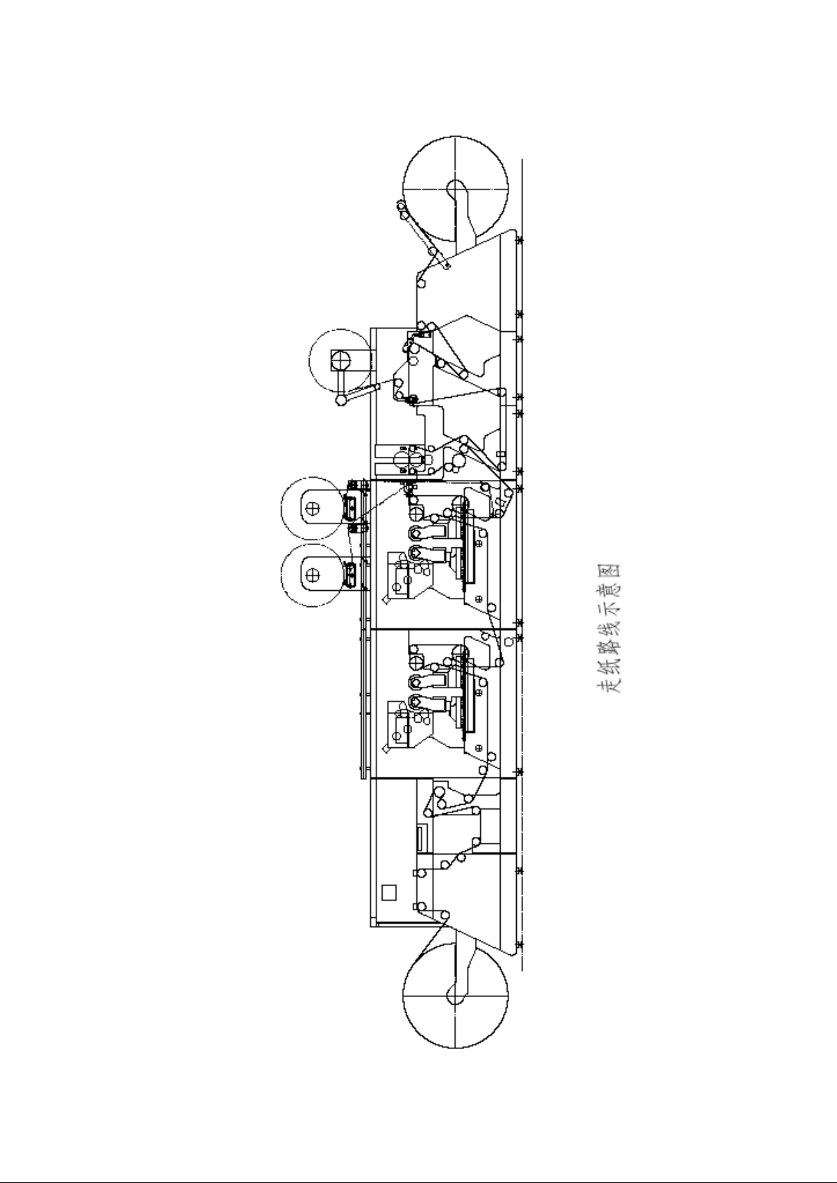
5.According to the paper route shown in Figure 3-1, put on the paper tape, click the
machine, confirm that there is no problem, and then you can carry out various
preparations before printing test.
Page 16
16
Figure 3-1
Page 17
17
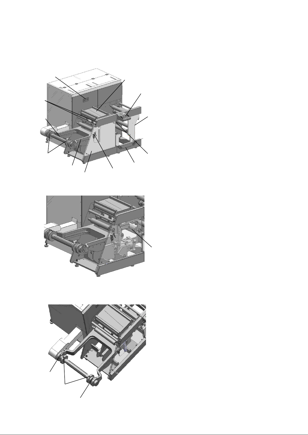
一、Overview of the structure
1 Unwinding unit
2 Lifting arm
3 Support bearings
4 Unwinding gas fluctuation shaft
5 Unwinding lift arm lift/drop button
6 Scrolling edge operation screen
7 Sheet laying table
8 Unwind-feeder operation screen
9 Feeder
10 Control paper adjustment
11 Emergency stop wires and cables
12 Air gun
1 Release button (Inner ring)
2 Mark Point(Outer Ring)
Two support bearings are installed on the
lifting arm to support the gas fluctuation
shaft equipped with paper rolls. Support
bearings consist of outer and inner rings.
The support bearing is fixed to the
lifting arm through the outer ring, and
the inner ring can rotate and push along
the shaft. Only when the release button on
the inner ring is aligned with the mark
point on the outer ring, the release
button can be pressed, the inner rings of
the two bearing are respectively pushed
outwards / inwards to remove / lock the
gas increase axis. The design of bearing
can prevent the accidental fall off of the
gas fluctuation shaft.
1 Lift arm supports air cylinder
Lift arm is used to support pre-printing
scroll by gas fluctuation shaft. Air cylinder is
used to support lift arm. If the air supply is
insufficient, the lifting arm will remain in its
current position. And then, as a safety
precaution, it drops very slowly. It prevents
injury to the operator and prevents damage to
the lifting arm. The role of the air cylinder
itself is used to stop the bottom of the lifting
arm.
1
1 2 2
12
2
3
5
4
6
7
8 9 10
11
1
二、Unwinding unit
2.1 Lift Arm and air cylinder
IV Unwind--Feeder
2.2 Support bearings
Page 18
18
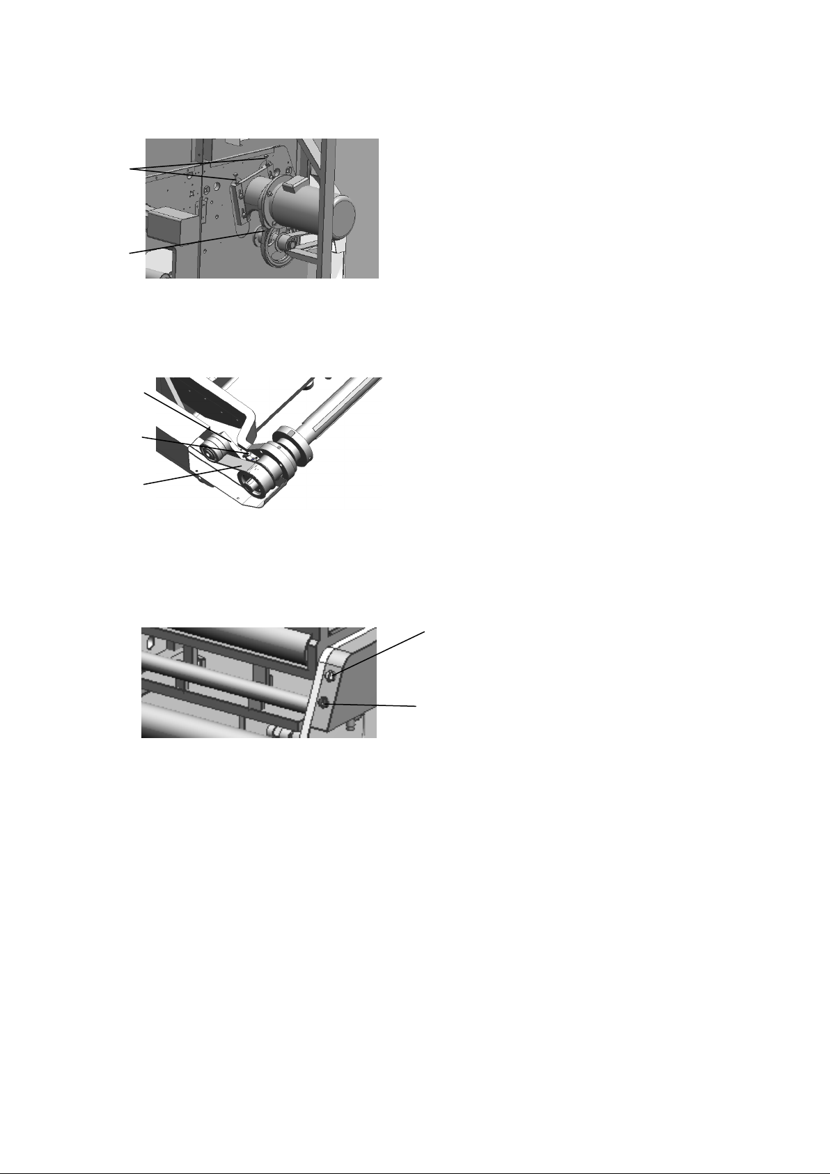
2.3 Unwinding main motor belt tensioning
1. adjusting screws
2. circle-arc tooth Synchronous belt
Keep the arc tooth synchronous belt
tight during running by adjusting the
screw so as to ensure the best
running state.
1. Tensioning support
2. adjusting screws
3. circle-arc tooth Synchronous belt
By adjusting the adjustment screw on
the tensioning support, circle-arc
tooth Synchronous belt is kept tight
during running in order to ensure the
best running state.
1. lift button
2. drop button
Lift / Drop Button is used to lift /
drop a pre-printed paper roll through
a lift arm
1
2
1
2
1 2 3
2.4 Unwinding drive belt tensioning
2.5 Lift and drop function of lifting arm
Page 19
19
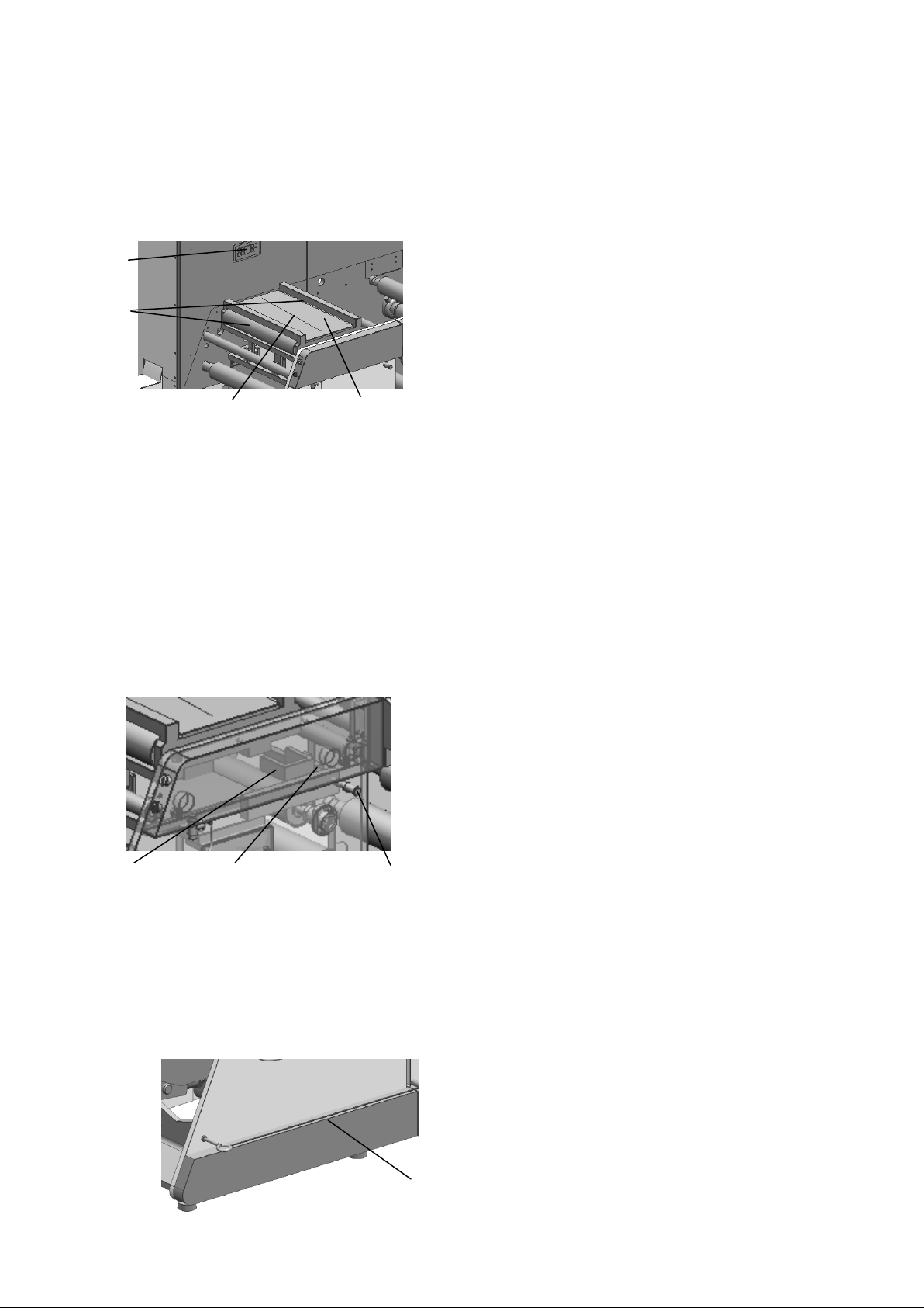
2.6 Scrolling edge control and sheet laying
1.Scrolling edge operation screen
2.Edge control roller
3.Cut line
4. Sheet laying table
The paper edge can be adjusted by
scrolling edge control. Place the
paper roll in the middle of the
printing unit when entering the
printing unit to begin printing.
The paper roll edge control
includes sheet laying table, where
the ends of different paper rolls
can be connected. After the new
paper roll is installed, the paper
is passed through the first edge
control roller controlled by the
paper roll edge, and the end of
the old and new paper roll is
respectively cut off along the
cutting line on the table. Through
the operation panel, scroll edge
control can be set up and related
operations
1 2 3
1. Fine-tuning handle
2. Sensor support
3. Sensor
Sensor support is used to
regulate the side of scroll edge
control. To make the adjustment
more precise, fine-tuning
handles can be used as needed.
1
1. Emergency stop wires and
cables
Emergency stop wires and
cables are installed at the
lower end of the machine's
operating side. If the
operator wants to stop the
entire machine, it will be
activated.
1
2
3
4
table
2.7 Emergency stop
Page 20
20
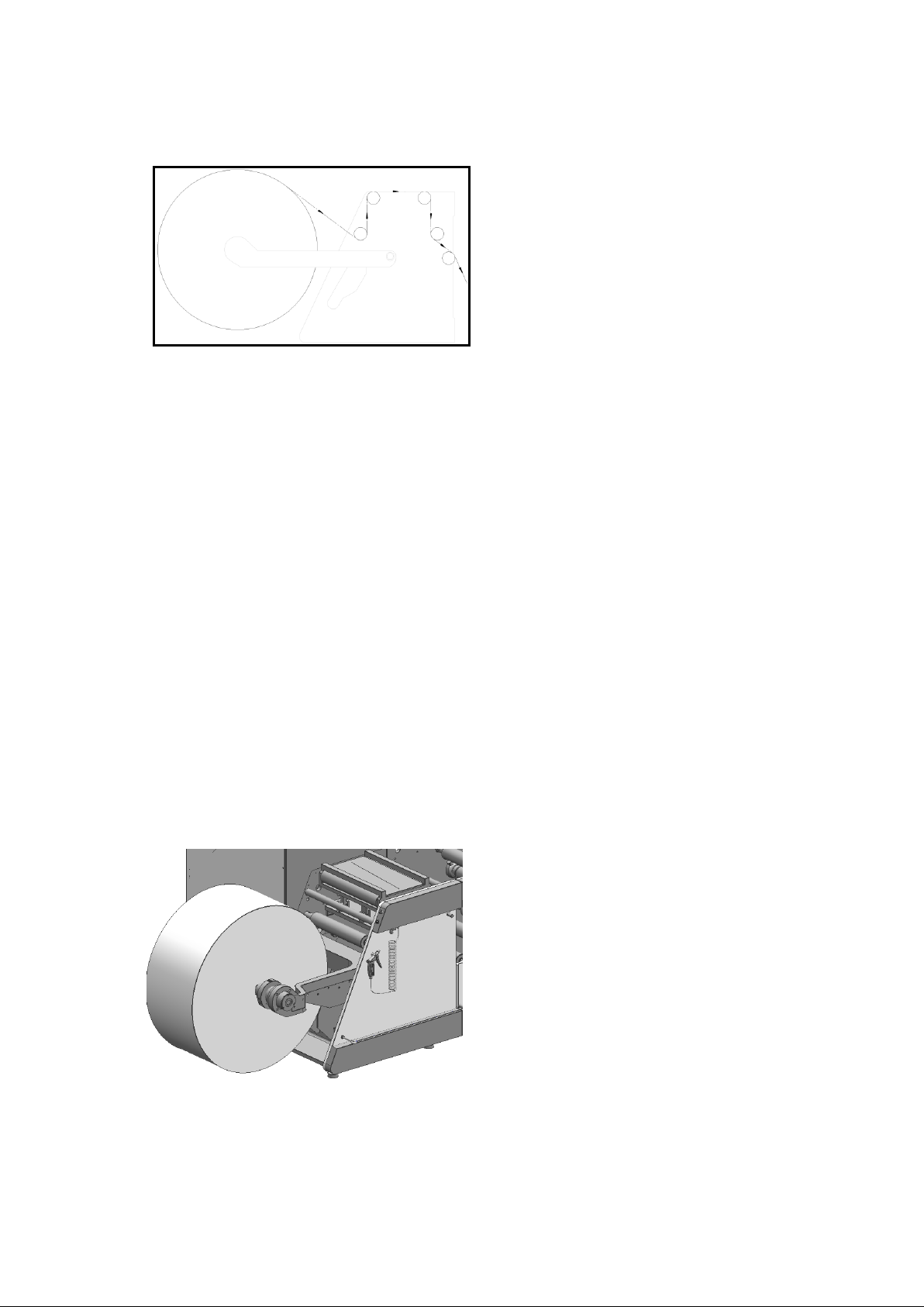
2.8 unwinding unit paper route
Rotate the inner rings of the two
bearing bearings so that the release
button is aligned with the mark point,
press the release button, push the inner
rings to the outside and take down the
gas fluctuation shaft, and let airbag
release. Then, the gas fluctuation shaft
is penetrated into the inner hole of the
pre-printed scroll. According to the
scale on the gas fluctuation shaft, the
paper is correctly installed. The air
fluctuation is inflated by air gun and
the scroll is fastened. Press the lifting
arm to lift / drop the operating button,
so that the lifting arm is in a suitable
position, and the inner ring of the two
bearings is rotated to align the release
button with the marking point. The
scroll installed on the gas fluctuation is
placed into the center hole, and the
inner ring of the two bearing is
respectively pushed to lock the gas
fluctuation shaft. Press the lift /drop
operation button to keep the lift arm in
a horizontal position.
2.9 Installation of scroll
Page 21
21
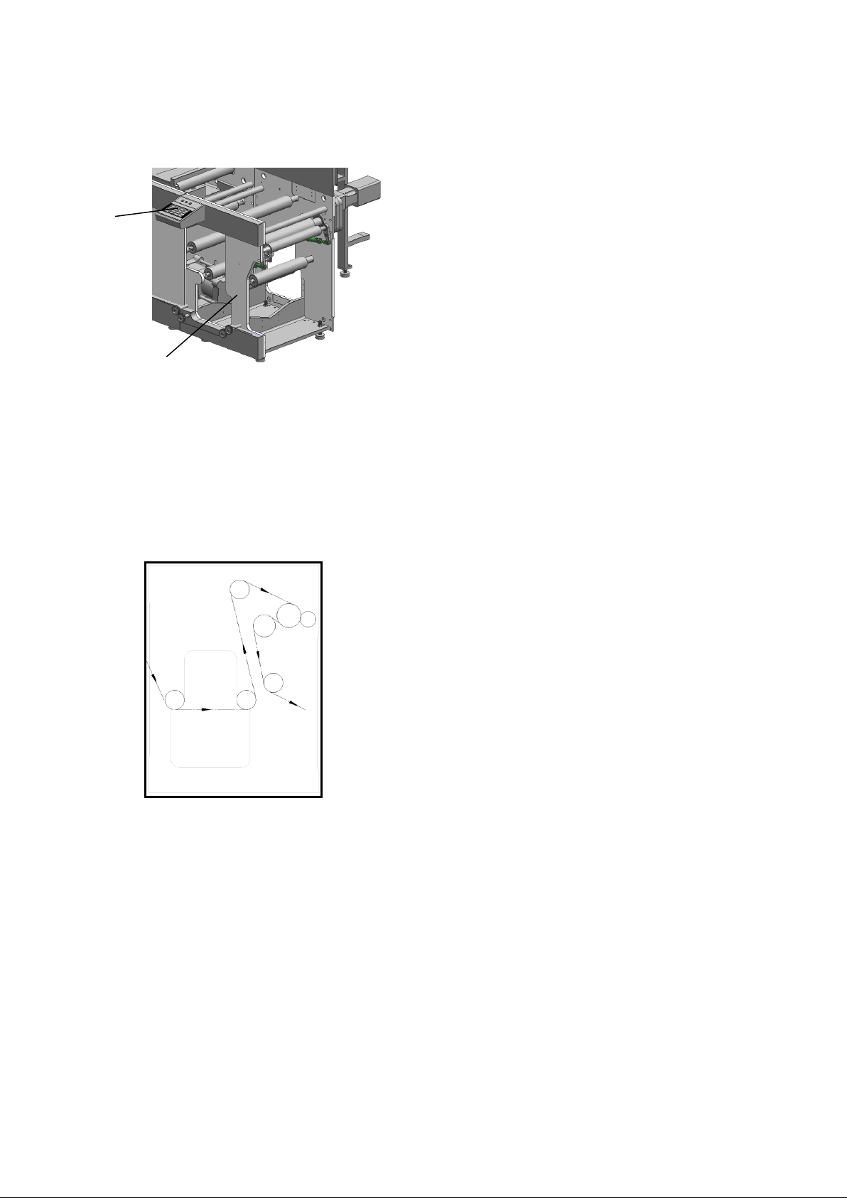
三、Feeder
1
2
1 Unwinding/feeder operation
Panel
2 Feeder unit
Feeder unit follows the
unwinding unit, and feeder unit
ensures that scroll remains
stable and unchanged during
printing. Through unwinding /
feeder operation panel, you can
set up various functions of
unwinding/feeder, such as turn
on/off, setting the scroll
diameter, tensioning and etc.
3.1 Summary
3.2 Feeder unit paper route
Page 22
22
V Offset printing unit
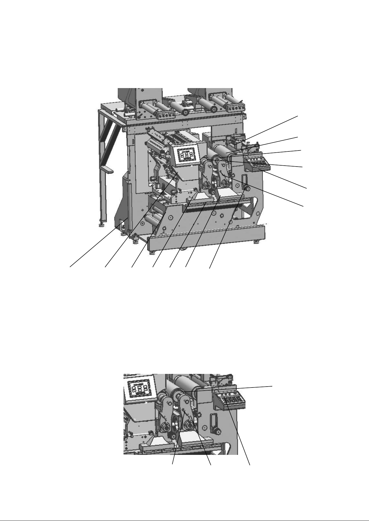
1 4 6 7 10
11
12
13
2 3 5 9 8
2 3 4
1
一、Composition of offset printing units
1、Frame (driving side) 2、water and ink unit 3、Frame (operating side) 4、Plate
roller bridge 5、Common platform 6、Blanket roller bridge 7、Regulating handle 8、
operating handle 9、Operational panel 10、plate cylinder 11、blanket cylinder 12、
impression cylinder 13、Coloring device
二、Replace blanket cylinder
2.1 steps
Page 23
23
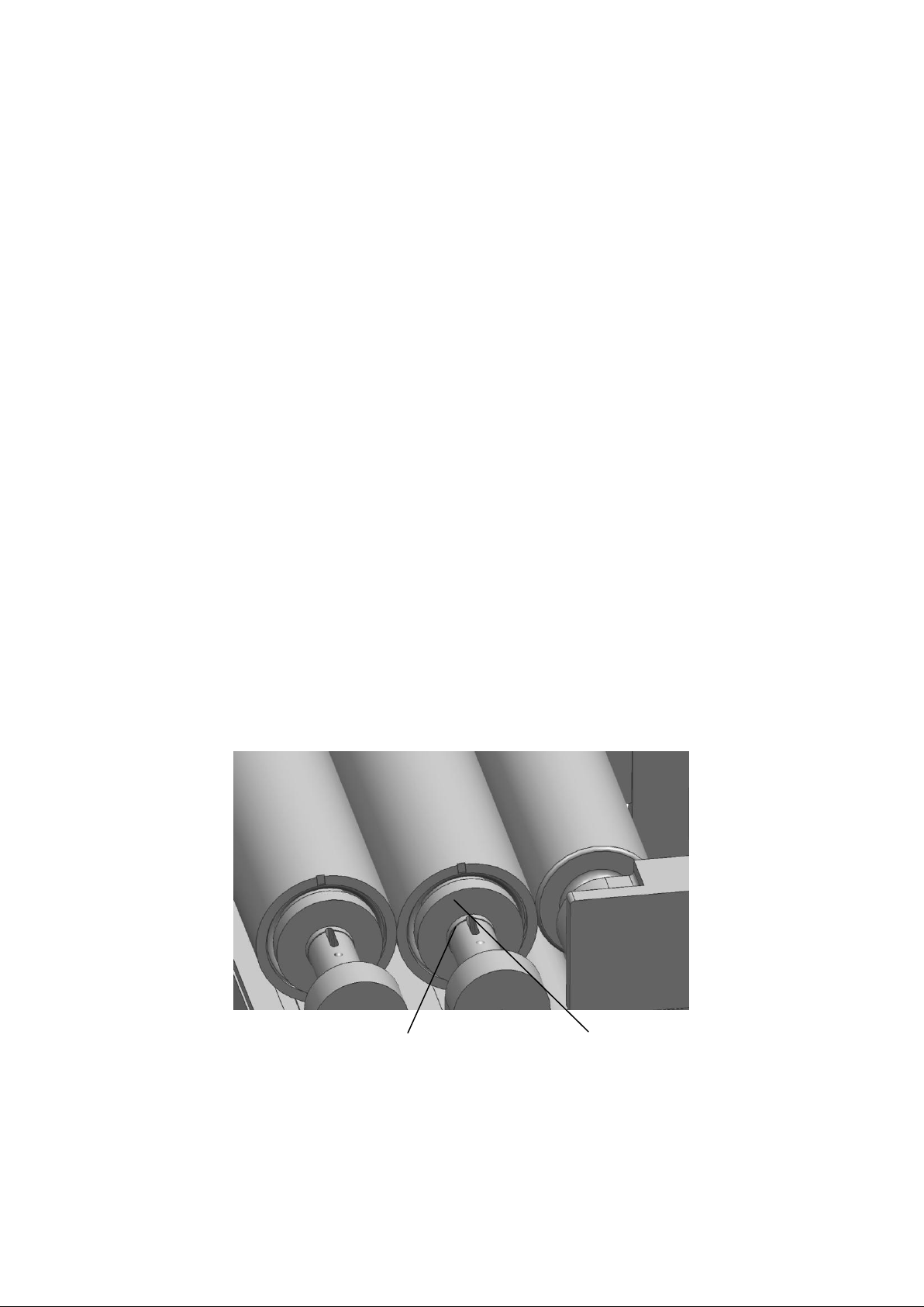
1)Select the cylinder exit key on the operating panel 3. At this time, plate roller
2
3
bridge and blanket roller bridge move to the printing "0" point position.
2)Turn the operating handle 2 counterclockwisely to the right swing arm 1
completely out of the state.
3)Turn the right arm 1 clockwisely to the lowest point.
4)Use the special hexagonal plate hand, the screw on the expansion sleeve 4 at both
ends of blanket cylinder is released. At this time, the cylinder and the core shaft
are separated.
5)Remove the cylinder along with both sides of the expansion sleeve from the core
shaft.
6)Remove the drive side expansion sleeve from the replaced cylinder and load it
into the new cylinder and load it into the machine core shaft.
7)Load the expansion sleeve on the operating side, use a special positioning plate
to registrate the position of the blanket cylinder notch.
8)Fasten the cylinder on the core shaft with the fastening screw on the fastening
sleeve of the special handle.
9)Close the right swing arm, rotate the handle clockwisely, and fix the swing arm.
2.2 Notes
1)When replacing the cylinder, it must be confirmed that the cylinder is completely
out of the state, otherwise the swing arm may not be in place
2)Load the operating side expansion sleeve 3 to ensure that the position of the
cylinder positioning gap 1 and the slot 2 on the core axis is accurate. Otherwise
there may be a phenomenon of uneven or wrong 180 degrees in the plate seam.
3)When locking screws on the sleeve, the force of the standard torque must be pre-
tightened. The operating side is 24N.。M. The driving side is 40N. 。M. Otherwise,
it will affect the printing effect and the service life of the expansion sleeve.
4)When replacing the cylinder, it is necessary to ensure that the mixing surface of
the cylinder, expansion sleeve and core shaft is clean; Otherwise, it will affect
Page 24
24
the outer circle beating after the cylinder is on the machine, resulting in an
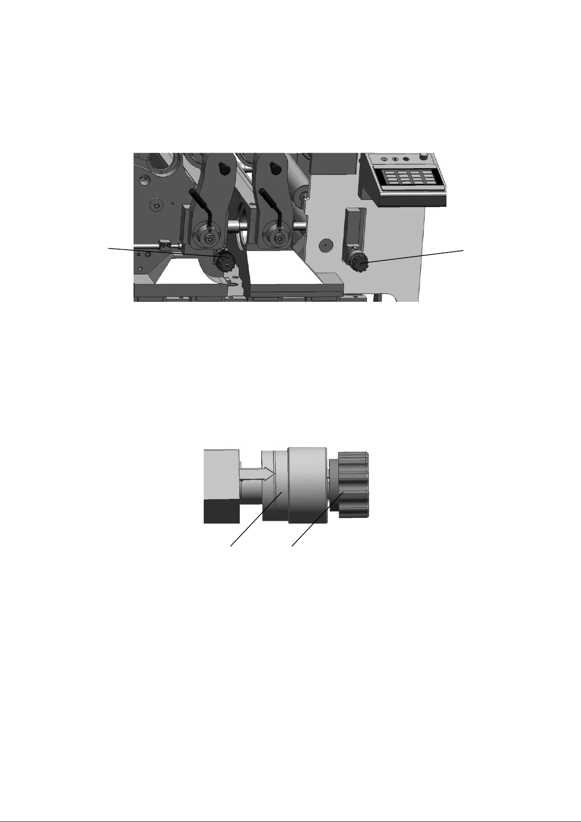
1 2 2
1
impact on the quality of the product.
三、Replace plate cylinder
The process is similar to replacing blanket cylinder.
四、Cylinder parallelism and pressure adjustment
1、The front adjusting handle 1 adjusts the parallel and printing pressure between
the plate cylinder and the blanket cylinder.
2、The back adjusting handle 2 adjusts the parallel and printing pressure between
the blanket cylinder and the impression cylinder.
Note: Before the machine leaves the factory, the parallel and printing pressure of
the cylinder is adjusted. In the offset printing state, the adjusting handle is
locked, and non-professionals must not adjust without authorization.
Adjusting parallel: Roller handwheel 1 round, change 0.04 mm. Turn clockwise to
increase the pressure on the operating side. Instead, turn counterclockwise to
reduce the pressure on the operating side.
Note: The front end of the pointer has been adjusted to be in the center of the
flower-wheel indicator slot at the factory.
Printing pressure: Handle 2 turns and changes 0.14. Turn clockwise and increase the
printing pressure; Turn counterclockwise, reduce printing pressure.
Note: The printing pressure between the cylinders will be automatically adjusted
according to the paper thickness entered in the PMC. This handle 2 will only be
activated when it is converted into a flexo printing state!
Page 25

25
五、Offset printing pressure setting
1.Before printing, according to the material thickness, you can find the paper
thickness setting menu at the PMC management center and enter the thickness.
This value is applicable to all units.
2.According to the actual printing effect, if you need adjust the printing
pressure as a whole, you only change the thickness data. Increasing the
material thickness will reduce the actual printing pressure as a whole.
3.If you need adjust the printing pressure of a single unit, select the
corresponding unit first and enter the corresponding data in the plate cylinder
and blanket cylinder.
Page 26
26
一、Summary
VI Offset printing water and ink uints
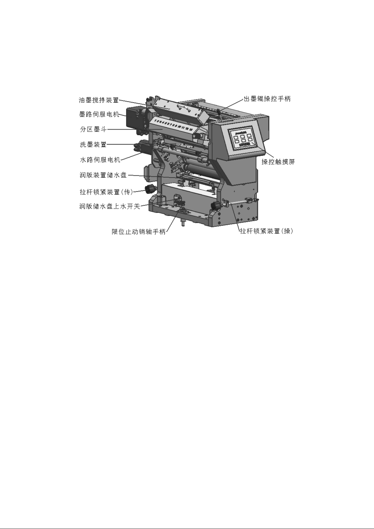
Fig.1-1 Water and ink unit
The water and ink unit in offset printing (ink transfer and dampening device) is
installed as an independent module on the slider of the linear guide rail at both
ends of the offset printing platform, and can be moved back and forth with the
slider on the linear guide rail. When offset printing, just lift up the limited stop
positioning pin handle and push the ink unit frame forward, so that the front
positioning surface of the wall plate on both sides of the frame and the positioning
block of the plate roller bridge on the offset printing platform are flattened.
Tighten the locking device on both sides of the lever. It makes water and ink unit
and plate roller bridge is connected into one. When offset printing is not carried
out, only the two sides of the lever locking device should be removed and the ink
unit frame should be pushed backwards. At this time, the water and ink unit should
be separated from the plate roller bridge and moved away to the limit position. The
limited stop positioning pin will automatically fall into the positioning hole and
will limit the position of the water and ink unit.
It is equipped with a ink remote control. There are 13 ink keys to control motor. It
can track and control the ink preset and ink color ratio adjustment on the central
console. There is an automatic ink mixing device driven by air cylinder, so as to
ensure that the ink roller can continuously supply ink evenly and steadily with high
Page 27

27
speed offset printing, thus ensuring the printing quality and printing stability of
under high speed offset printing.
It is equipped with an ink roller cooling device. Cooling water can be used to
control the ink roller and ink temperature, which is in the inner cavity of the ink
roller and the 2nd and 3rd ink roller cores. To make ink performance is not affected
by the printing time and high-speed printing and to ensure the stability of printing
quality.
The ink transmission device and dampening device are two independent transmission
systems, which are driven and controlled by the ink servo motor and the water servo
motor seperately. It is also equipped with an ink roller automatic cleaning device.
When it is necessary to clean the ink roller, the ink roller (including the water
roller) of the ink transmission device can be automatically cleaned by manipulating
the button on the touch screen.
二、Notes
2.1、Use of UV offset printing inks
UV lamp drying device is provided on each offset unit. All rollers are UV rollers,
which are suitable for UV ink (UV curing ink) printing. When using printing ink,
because UV offset ink chemical properties are different from traditional offset ink,
the use of traditional offset ink will affect the transmission performance of water
and ink transfer.
(1)The quality of rollers is very important to ensure the printing quality. Only
good quality rollers can provide the best transmission effect.
(2)Accurate adjustment of the best pressure between the rollers can optimize the
performance of water and ink transmission and extend the service life of the rollers.
(3)High quality rollers and the best pressure can ensure that the offset press has
a high quality of printing
2.2、Basic requirements for printing
(1)Adjust the output parameters of UV dryer to printing requirements.
(2)Use PS plate suitable for UV offset printing. If you use an ordinary PS plate,
you must perform a toasting treatment to improve its corrosion resistance.
(3)Use UV self-adhesive blanket.
(4)Use UV ink special auxiliaries, additives and cleaning agents.
(5)UV ink must not be mixed with traditional ordinary offset ink, and do not mix
with other types of UV ink.
(6)Do not use UV ink that beyond warranty period.
(7)Do not overuse additives in UV ink. If overuse, it is easy to cause ink film
drying and other problem.
Page 28

28
(8)Compared with the traditional ordinary offset ink, UV ink balance tolerance is
narrower, it is easy to cause ink emulsification, dirty plate, etc.. Especially at
the beginning of printing, the supply of UV ink in the ink ductor is not very smooth,
and then ink is gradually increased. Therefore, it is important to adjust the amount
of ink and water supply to reach the balance.
2.3、Storage, Maintenance and Transportation of rollers
(1)After printing, make sure to clean the ink on the surface of the roller, and
the ink can not be left on the roller.
(2)If there is a hard film on the roller surface, it musts remove as early as
possible. If there is crack on roller glue surface, it musts grind in time.
(3)Temporary storage of rollers must be placed on the shelf.
(4)When the roller is kept for a long time, it must be supported at both ends of
the shaft. There should be space between the rollers. It is forbidden to squeeze
each other to prevent the adhesive from being deformed or sticking. The surface of
the long-term preservation rollers may produce cracks, which must be ground before
use.
(5)Rollers should be kept in a cool, dry, ventilated place in the room. Rollers
are wrapped in paper or plastic film to prevent aging of the rubber surface. Storage
should not be with acids, bases, oils, and sharp hard materials, so as to avoid
corrosion or bump. The metal parts exposed at both ends of the roller should be
protected against rust.
(6)Rollers should be loaded into wooden cases when transportation. In order to
avoid abrasions, there must be a space between the rollers and between the rollers
and the boxes.
2.4、UV ink storage
UV ink should be kept in a cool and dry room, avoiding room temperature above 30 °C
or direct sunlight.
2.5、Clean rollers
During the printing process, impurities such as paper hair, paper powder, ink will
adhere to the surface of the roller, or they will be deposited in the micropores on
the surface of the roller or in liquid, which will easily cause the surface of the
roller to harden (glaze). Thus it makes influence on the ink transfer performance of
the roller. Therefore, in addition to ink replacement, the ink transfer and
dampening device should also be thoroughly cleaned once a week at least. When
printing coated paper or plastic film, the time interval for cleaning rollers need
to be shortened to 3-4 days. When the ink transmission device is not used for a long
time, the ink bucket and the ink roller must also be cleaned. After cleaning, wipe
with a soft, clean, fiberless fluff with a good absorbent cloth.
Specially Recommended Method for Cleaning UV Ink Roller
(1)Close the ink knife in the ink washers, use UV ink special cleaning agent to
pre-clean and remove ink till the ink roller surface is clean.
Page 29
29
(2)Remove the ink knife, use a deep cleansing ointment on the cleaned ink roller
for deep cleaning, then start the machine to make the ink roller running for 3 to 5
minutes, the deep cleaning cream can clean the stubborn ink wax.
(3)Then spray the calcium removal agent on the ink roller, start the machine to
make the ink roller running for 3 to 5 minutes, so that it is fully mixed with the
cleaning cream on the ink roller.
(4)About 5 minutes shut down, so that the roller calcium removal agent and
cleaning cream stay on the roller chemical effect.
(5)Close the ink knife once again, start the machine to make the ink roller
running 3 to 5 minutes, use the UV wash water to clean the roller again, and finally
use water to thoroughly wash the roller clean.
After deep cleaning, the surface of the roller is clean and the elastic of the
rubber layer is restored, and the ink transfer performance is improved.
If it is not possible to clean the surface of the roller with stubborn wax, remove
the roller from the machine for manual cleaning. If it is not possible to clean the
surface, the rollers must be replaced
三、Roller Installation
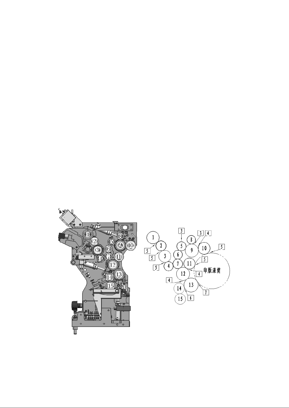
3.1、Recommended Pressure for Printing Roller Adjustment
Figure 3.1 shows the recommended pressure for the adjustment of ink and water
rollers. The width of the indentation is shown in the list in millimeters.
Fig.3.1 The recommended pressure for the adjustment of ink and water rollers
Page 30
30
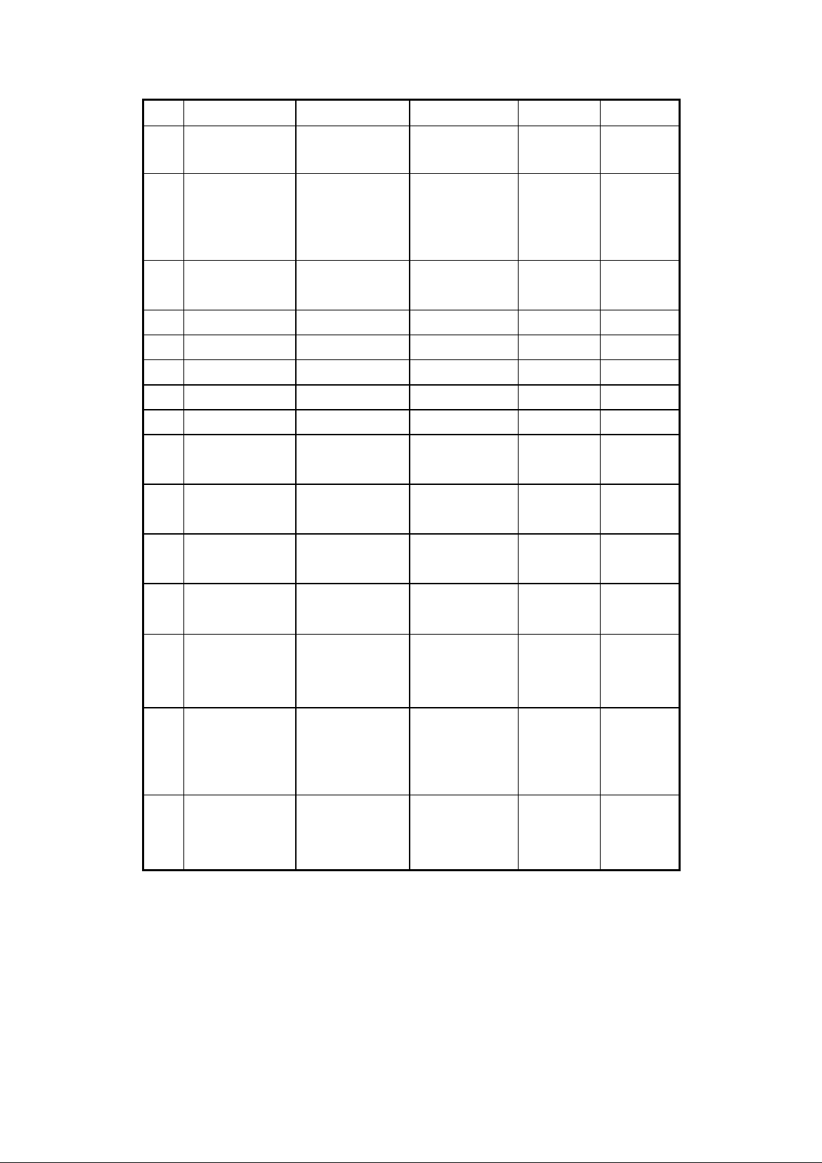
No.
Name
Drawing No.
Diameter(mm)
Material
Remarks
1
Ink fountain
roller
B1-1203-05/0
φ 70
Metal
2
Ink
distributor
roller
B1-1204-03/0
φ 57
Rubber
UV
3
Ink vibrating
roller
B1-1205-02/0
φ 67.8
Plastic
4
Rider roller
B1-1206-12/0
φ 52
Rubber
UV
5
Rider roller
B1-1206-03/0
φ 52
Rubber
UV
6
Rider roller
B1-1206-10/0
φ 50
Plastic
7
Rider roller
B1-1206-11/0
φ 54
Rubber
UV
8
Rider roller
B1-1206-02/0
φ 48
Rubber
UV
9
Ink vibrating
roller
B1-1205-01/0
φ 74
Plastic
10
Form inking
roller
B1-1207-01/0
φ 67
Rubber
UV
11
Form inking
roller
B1-1207-19/0
φ 63
Rubber
UV
12
Ink vibrating
roller
B1-1205-06/0
φ 74
Plastic
13
Form
dampening
roller
B1-1207-20/0
φ 80
Rubber
UV
14
Metering
roller
B1-1222-01
φ 60
Metal
Chromium
Roller
15
Water
fountain
roller
B1-1222-02
φ 60
Rubber
3.2、Installation sequence of printing rollers
Installation sequence of printing rollers
Rider roller 8 →Rider roller 4 → Rider roller 7,6,5 →ink distributor roller 2 →
Form inking roller 10,11, and Form dampening roller 13 →Water fountain roller 15 →
Metering roller 14
3.3、Installation method of printing rollers
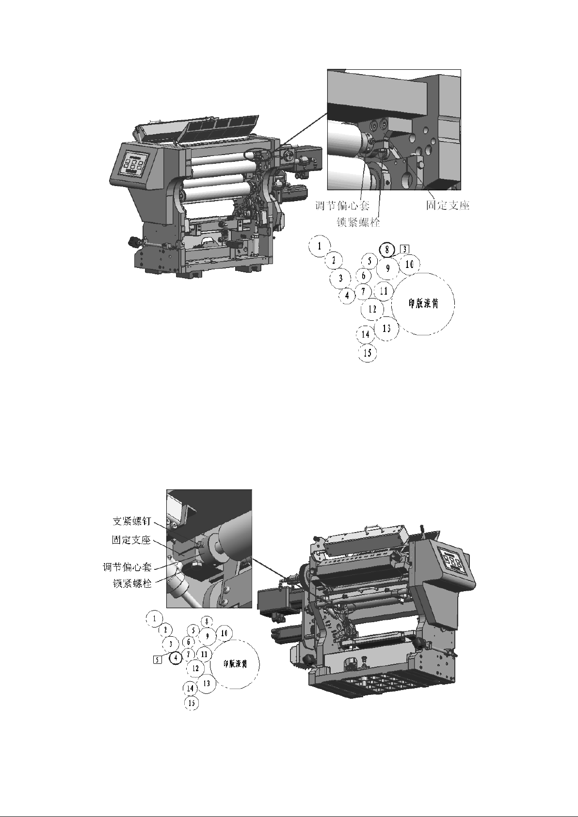
3.3.1 Installation of Rider roller 8
Page 31
31
Fig. 3.3.1 Installation of Rider roller 8
Installation Method: See Fig.3.3.1, Loosen the locking bolts on the fixed support
seats on both sides, and load the adjusting eccentric sleeve on the shaft heads of
the rider roller into the fixed support seats on both sides respectively, then
adjust the rider roller parallel to ink vibrating roller, and tighten the locking
bolts on both sides of the fixed support seats., Both ends of the rotation adjust
the eccentric sleeve to tighten the screw into the ring groove and tighten it firmly.
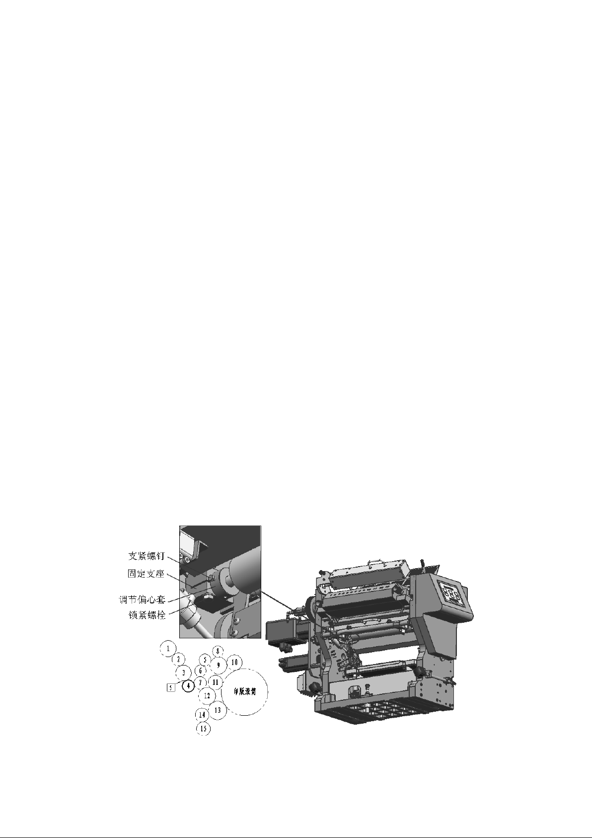
3.3.2、Installation of rider roller 4
Fig.3.3.2 Installation of Rider roller 4
Page 32
32
Installation Method: See fig.3.3.2, Loosen the locking bolts on the fixed support
seats on both sides, and load the adjusting eccentric sleeve on the shaft heads of
the rider roller into the fixed support seats on both sides respectively, then
adjust the rider roller parallel to ink vibrating roller, and tighten the locking
bolts on both sides of the fixed support seats., adjusting the eccentric sleeve with
the screw into the ring groove and tightening firmly at both ends
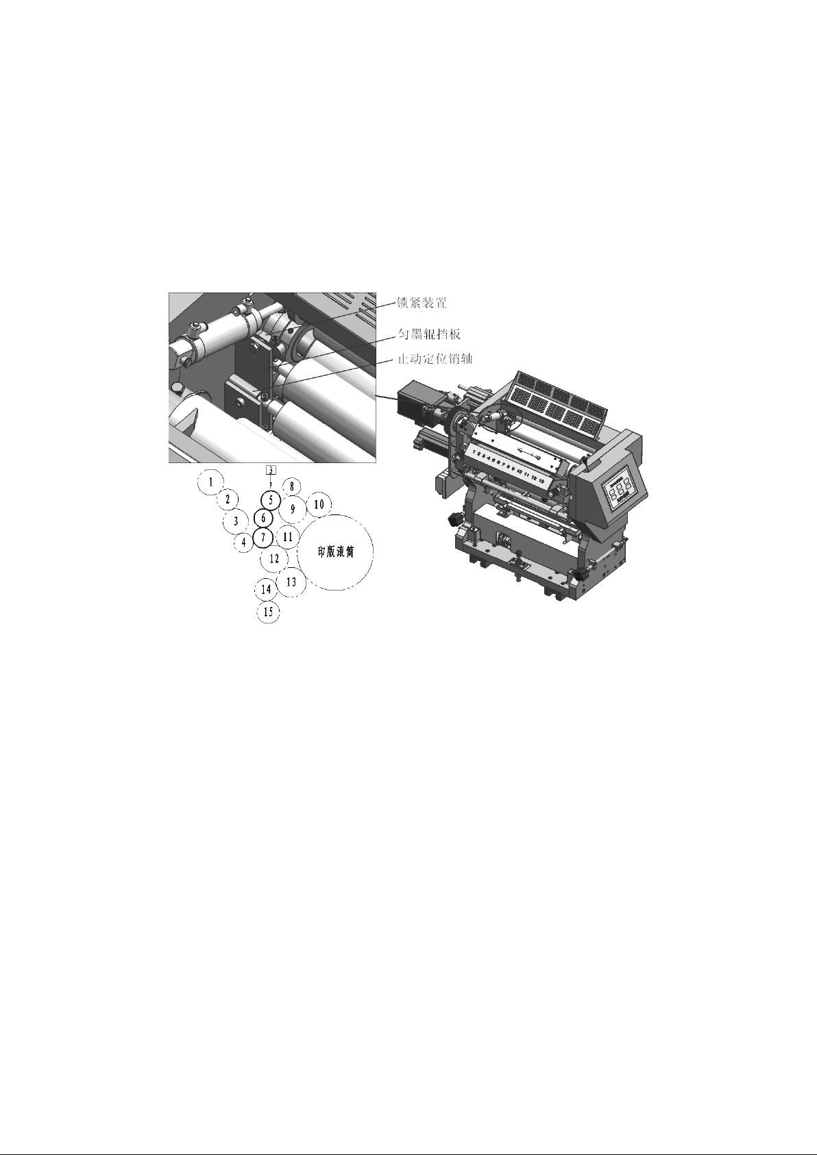
3.3.3、Installation of rider roller 5,6,7
Fig.3.3.3 Installation of Rider roller 5,6,7
Installation Method:See fig.3.3.3, Put the rider roller 7, 6, and 5 into the stop
positioning pin of the two sides baffle in sequence, adjust the fastening screws on
the two sides of the locking device, so that the above rider roller surfaces are
close to each other. Tighten the nut on the fastening screw to hold it firmly.
Page 33
33
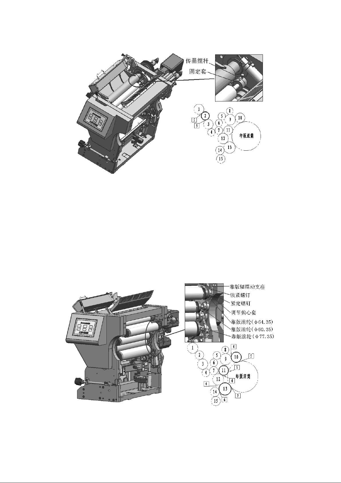
3.3.4、Installation of ink distributor roller 2
Fig.3.3.4 Installation of ink distributor roller 2
Installation method: see Fig.3.3.4, Loosen the fastening screws on both sides of the
ink swing rod, and load the two ends of the ink distributor roller into the inner
holes of the two sides, then adjust the parallel of the ink distributor roller and
the ink vibrating roller, tighten the fixing screw of the control side ink
distributor rod, tighten the screw on both sides. Tighten the screw on the fixed
sleeve at both ends of the spinning ink roller into the ring groove and tighten and
fix firmly.
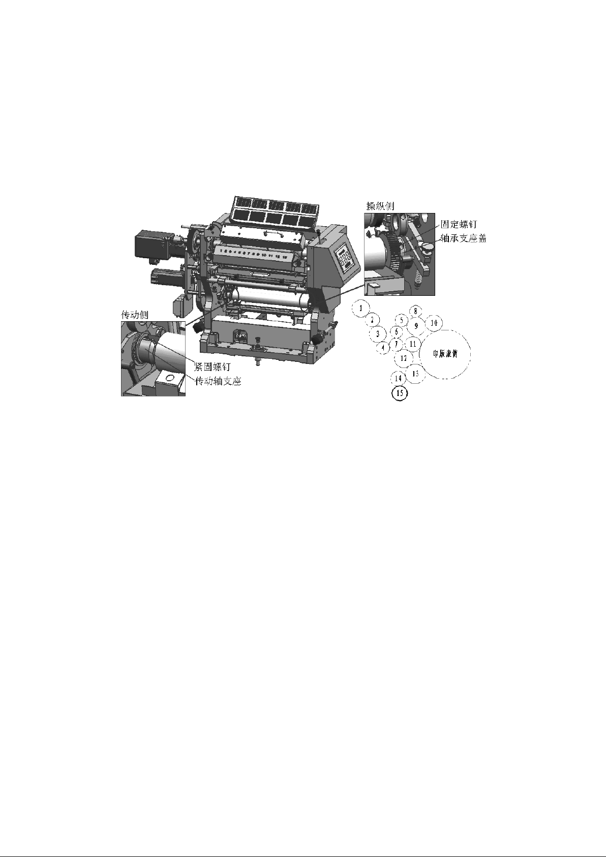
3.3.5、Installation of Form inking roller 10,11 and Form dampening roller 13
Fig.3.3.5 Installation of Form inking roller 10,11 and Form dampening roller 13
Installation method: see Fig.3.3.5, The corresponding plate roller is installed at
both ends of the plate roller (Pls note that the eccentric direction of the plate
Page 34
34
roller needs to be the same), and the locking screws on both sides of the plate
swing support are loosened. The fixed sleeves at both ends of the plate roller are
respectively loaded into the inner holes of the swing supports on both sides. The
adjustment of the plate roller is parallel to ink vibrating roller. The locking
screws on the swing supports are firmly tightened, and the tightening screws on the
eccentric sleeve are adjusted at both ends. Into the ring slot and tighten.
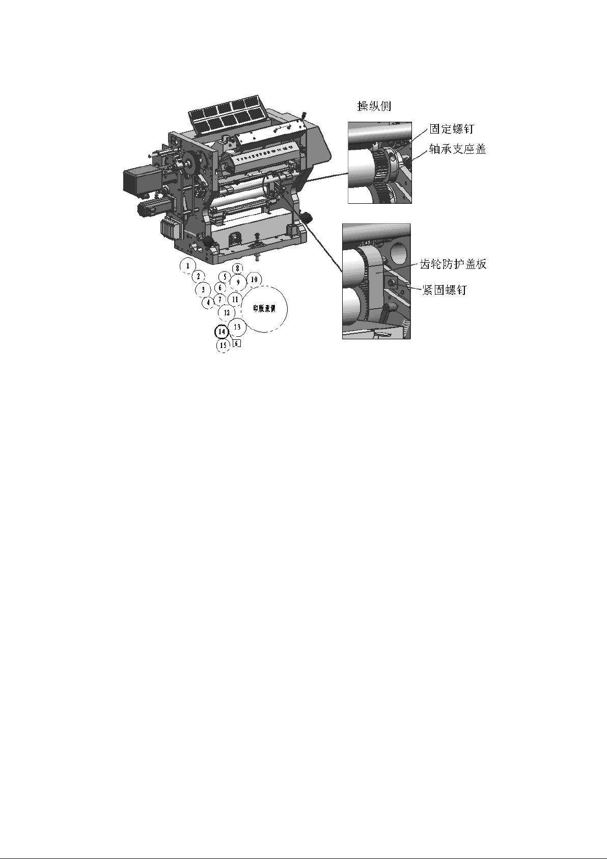
3.3.6、Installation of Water fountain roller 15
Fig.3.3.6 Installation of Water fountain roller 15
Installation Method: See Fig.3.3.6, Remove the bearing support cover on the inner
side of the operating side of the machine, install the two ends of the water
fountain roller in place (the side of the gear on the water fountain roller is the
operating side), and screw the driving side fastening screw. Reload the bearing
support cover of the operating side as mentioned above, tighten the fixed screw on
the cover, tighten the driving side fastening screw. (Note that the bearing cover
and support are paired parts that need to be used in combination with the serial
number).
Page 35
35
3.3.7、Installation of metering roller 14 and gear protection cover
Fig.3.3.7 Installation of metering roller 14
Installation Method: See Fig.3.3.7, Remove the bearing support cover on both sides
of the machine and install the two ends of the metering roller in place (the side of
the gear on the metering roller is the operating side). Re-install the two sides of
the bearing support cover removed from the above (note that the bearing support
cover and the support are paired parts, need to be used in combination with the
number, can not be mixed), and the tightening screw is firmly fixed. Install the
gear protection cover, tightening screw fixed firmly.
Note: The adjustment of the metering roller must ensure that the metering roller is
parallel to water fountain roller, and the gear on the metering roller is meshed
with the upper gear of water fountain roller. In the future machine maintenance, in
order to prevent gear wear and rust, this meshing gear should be manually added oil
at least once a day.
四、adjustment of printing rollers
The adjustment quality of ink rollers and water rollers has a great influence on the
printing quality and service life of the machine. The poor adjustment of pressure
between rollers or the non-parallel adjustment between rollers will lead to abnormal
extrusion and friction between rollers, resulting in an increase in the surface
temperature of the roller body., aggravated the wear of the roller.
Page 36
36
The adjustment of the ink rollers and the water rollers shall be made at normal room
temperature, and it must be ensured that the adjusted rollers are parallel to each
other.
The ink rollers and the water rollers should be adjusted before it is put into
operation and after a long period of use.
4.1、Initial adjustment(basic adjustment)
The initial adjustment of the ink rollers and the water rollers is carried out
before supplying ink. After the installation of the ink rollers and the water
rollers, the distance between the two rollers needs to be initially adjusted.
Adjustment method: Loosen the adjusting locking devices on both sides of the roller
to be adjusted, take 2 pieces of 0.05 mm thickness plugs, place them at both ends of
the roller to be adjusted, then adjust the adjustment devices on both sides of the
roller to be adjusted, and pump the plug at both ends until the pump plug the piece
needs to be extracted with the same force. Adjusting device on both sides of the
locking roll to be adjusted.
4.2、The sequence and method of fine adjustment of Printing Rollers
During the fine adjustment of the ink and water rollers, the ink unit module must be
connected with the roller bridge on the offset printing platform so that the machine
can be started to run the ink transfer and dampening device.
The pressure of ink roller and water roller is carefully adjusted in the following
order and adjustment method.
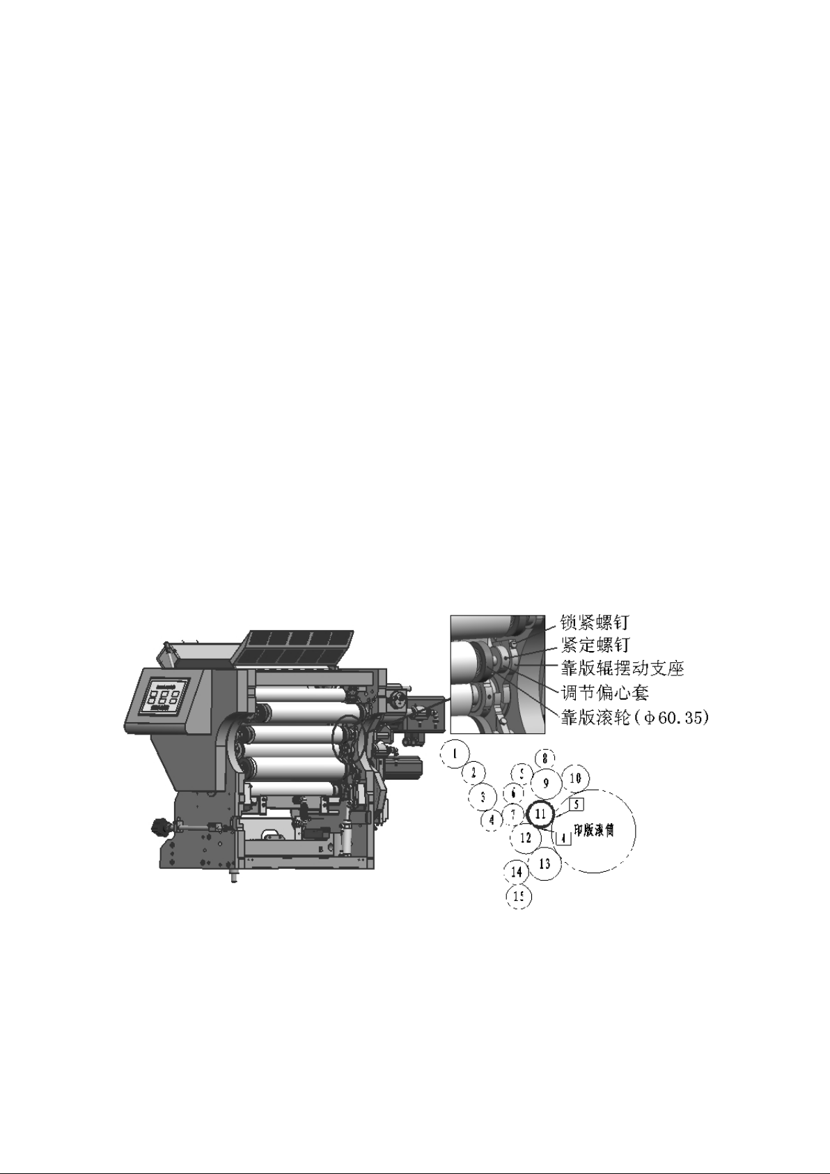
4.2.1、Fine adjustment of the pressure between the rider roller 4 and ink
vibrating roller 3
Fig.4.2.1 the pressure between the rider roller 4 and ink vibrating roller 3
Page 37
37
Installation method:See Fig.4.2.1, Apply a light ink(such as yellow ink) on the ink
roller, start the machine to let the ink evenly; After the ink is well and stop the
machine. Dot the machine again to view the indentation width left on the roller. The
indentation width between the rider roller 4 and ink vibrating roller 3 is 5mm, and
the indentation width is uniform and consistent in the length direction. If the
indentation width does not meet the requirements, adjust the adjustment device at
both ends of the rider roller 4
When adjusting, stop running the machine to ensure that the machine does not
accidentally start. Loosen the locking bolts on the fixed supports on both sides of
the rider roller 4, rotate and adjust the eccentric position of the adjusting
eccentric sleeve at both ends of the rider roller 4 (if the positive rotation
indentation widens, the reverse rotation indentation narrows), and review the
indentation width until the indentation width meets the requirements. After the
adjustment is completed, the locking bolts on the fixed supports on both sides must
be tightened to adjust the position of the eccentric sleeve to be firmly fixed
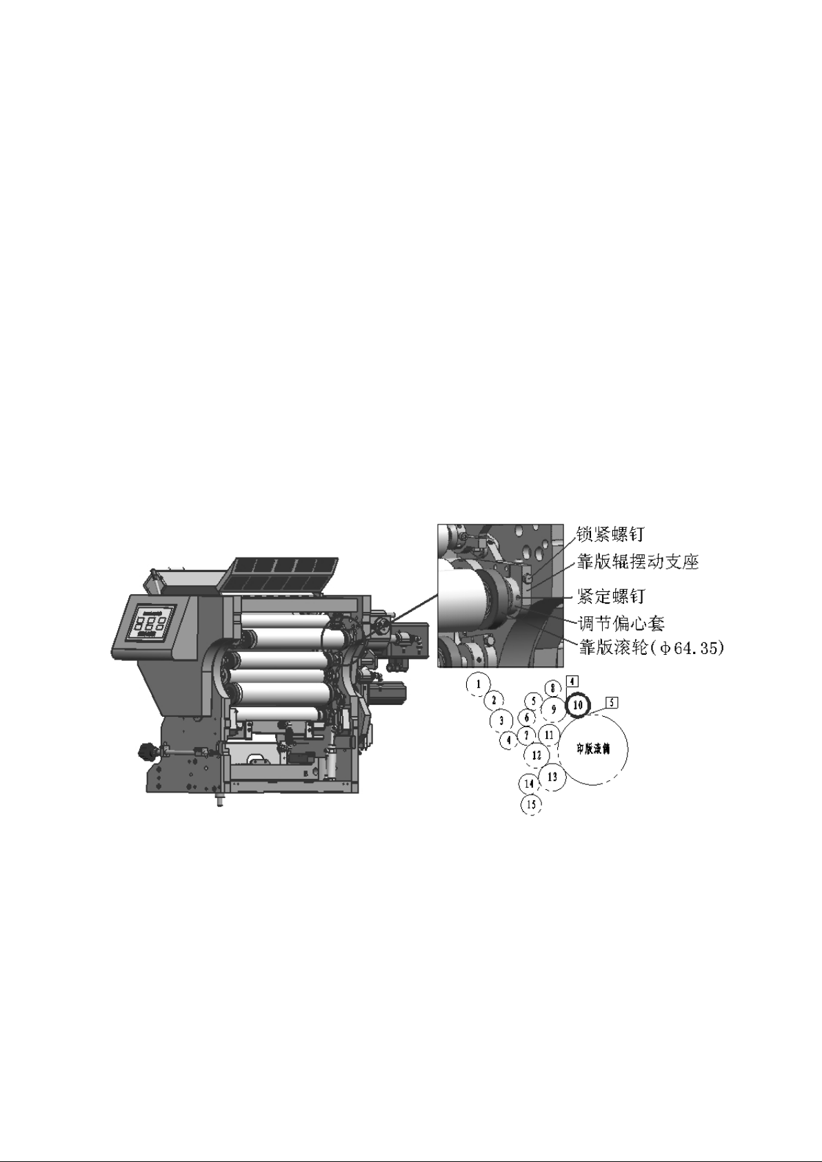
4.2.2、Fine adjustment of the pressure between form inking roller 11 and the
ink vibrating roller 12
Fig.4.2.2 Fine adjustment of the pressure between form inking roller 11 and the ink
vibrating roller 12
Adjustment method: see Fig.4.2.2, With the above 4.2.1, light ink (such as yellow
ink) and indentation methods are used to check that the indentation width between
Page 38
38
the form inking roller 11 and ink vibrating roller 12 is required to be 4mm, and the
indentation width is uniform in the length direction. If the indentation width does
not meet the requirements, the adjustment device at both ends of the ink roller 11
needs to be adjusted.
When adjusting, stop running the machine to ensure that the machine does not
accidentally start. Loosen the locking screws on the swing supports on both sides of
the form inking roller 11, rotate and adjust the eccentric position of the adjusting
eccentric sleeve at both ends of the form inking roller 11(if the positive rotation
indentation widens, the reverse rotation indentation narrows), and review the
indentation width, Until the indentation width meets the requirements. After the
adjustment is completed, the locking screws on the swing supports on both sides must
be tightened to adjust the position of the eccentric sleeve to be firmly fixed.
4.2.3、Fine adjustment of the pressure between the form inking roller 10 and
ink vibrating roller 9
Fig.4.2.3 Fine adjustment of the pressure between the form inking roller 10 and ink
vibrating roller 9
Adjustment method: see Fig.4.2.3, With the above 4.2.1, light ink(such as yellow ink)
and indentation methods are used to check that the indentation width between form
inking roller 10 and ink vibrating roller 9 is required to be 4mm, and the
indentation width is uniform in the length direction. If the indentation width does
Page 39
39
not meet the requirements, adjust the adjustment device at both ends of form inking
roller 10.
When adjusting, stop running the machine to ensure that the machine does not
accidentally start. Loosen the locking screws on the swing supports on both sides of
the form inking roller 10, rotate and adjust the eccentric position of the adjusting
eccentric sleeve at both ends of form inking roller 10 (if the positive rotation
indentation widens, the reverse rotation indentation narrows), and review the
indentation width, Until the indentation width meets the requirements. After the
adjustment is completed, the locking screws on the swing supports on both sides must
be tightened to adjust the position of the eccentric sleeve to be firmly fixed
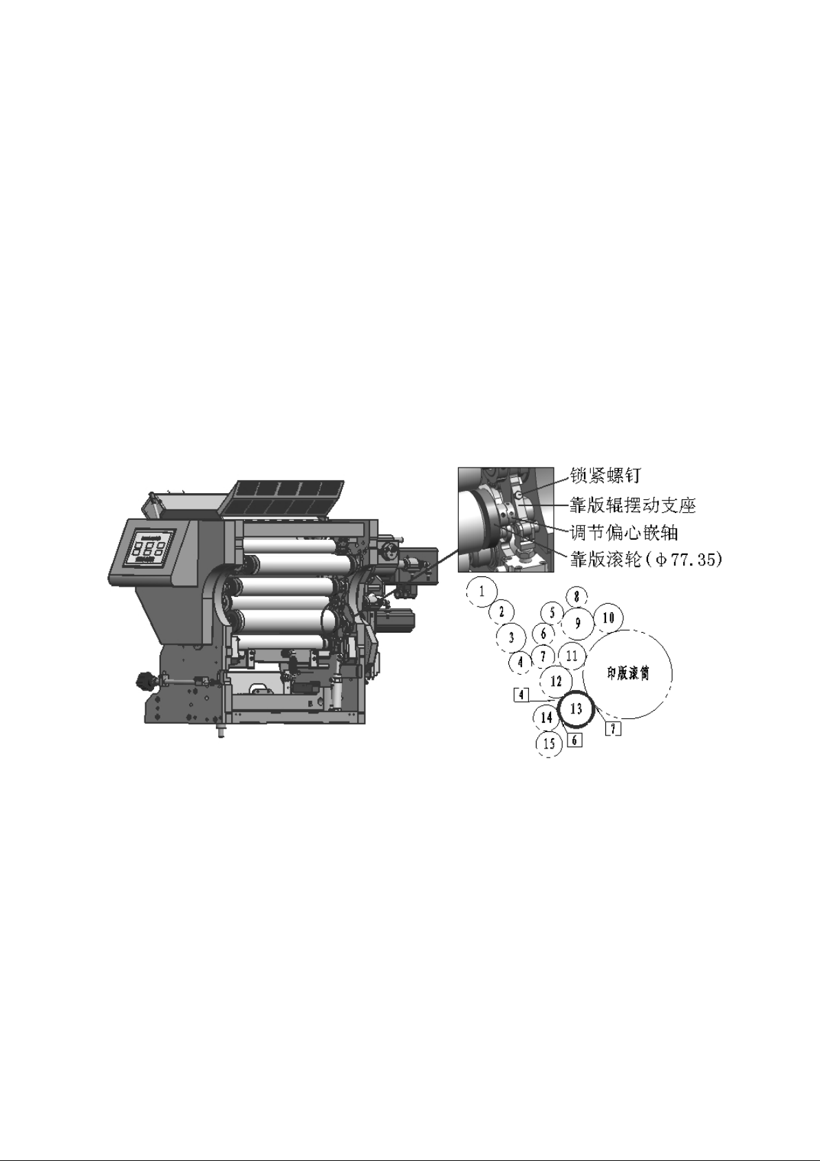
4.2.4、Fine adjustment of the pressure between the form dampening roller 13 an d
ink vibrating roller 12
Fig.4.2.4 Fine adjustment of the pressure between the form dampening roller 13 and
ink vibrating roller 12
Adjustment method: See fig.4.2.4, With the above 4.2.1, light inks(such as yellow
inks) and indentation methods are used to check that the indentation width between
the form dampening roller 13 and ink vibrating roller 12 is required to be 4mm, and
the indentation width is uniform in the length direction. If the indentation width
does not meet the requirements, it is necessary to adjust the adjustment device at
both ends of the fomr dampening roller 13.
Page 40
40
When adjusting, stop running the machine to ensure that the machine does not
accidentally start. Loosen the locking screws on the swing supports on both sides of
the form dampening roller 13, rotate and adjust the eccentric position of the
adjustable eccentric axis at both ends of form dampening roller 13 (if the positive
rotation indentation widens, the reverse rotation indentation narrows), and review
the indentation width, Until the indentation width meets the requirements. After the
adjustment is completed, the locking screws on the swing supports on both sides must
be tightened to adjust the position of the eccentric axis to be firmly fixed.
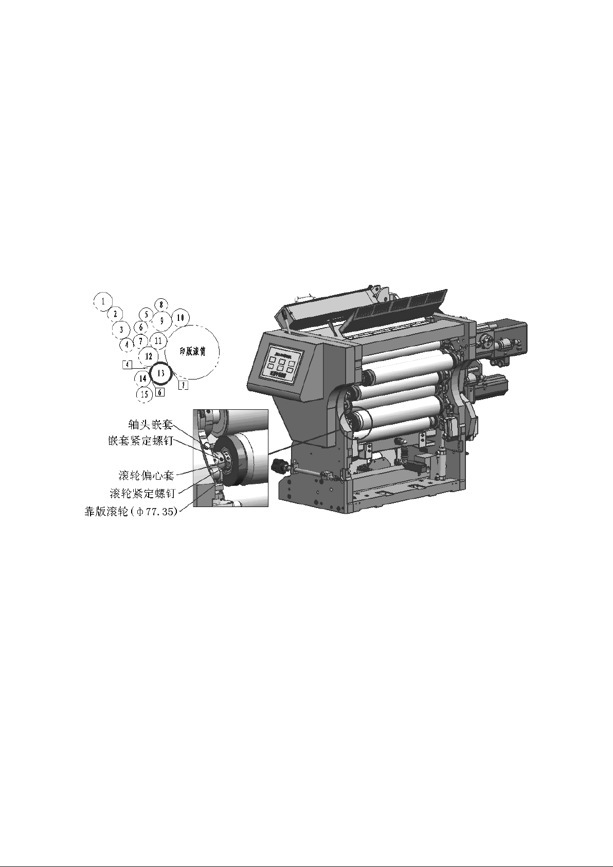
4.2.5、Fine adjustment of the pressure between the form dampening roller 13 an d
the plate cylinder
Fig.4.2.5 Fine adjustment of the pressure between the form dampening roller 13 and
the plate cylinder
Adjustment method: see Fig.4.2.5, Installation of plate cylinder (including printing
plate) in place, the same as the use of light ink(such as yellow ink) and
indentation method inspection, requiring indentation width between the form
dampening roller 13 and the plate is 7mm, And the indentation width is uniform in
the length direction. If the indentation width does not meet the requirements,
adjust the adjustment device at both ends of form dampening roller 13.
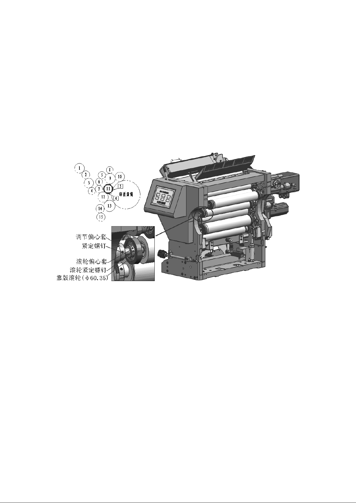
When adjusting, loosen the fastening screw on the nested axles on both sides of the
form dampening roller (Note: Do not loosen the roller fastening screw on the
eccentric sleeve of the roller at both ends), and rotate to adjust the eccentric
Page 41
41
position of the eccentric sleeve (if the positive rotation indentation widens, The
reverse rotation indentation becomes narrower; At this point, the core shaft of the
form dampening roller will rotate together with the eccentric sleeve of the roller),
and the indentation width will be reviewed until the indentation width meets the
requirements. After the adjustment is completed, the fastening screws on the nested
shaft heads on both sides must be tightened, and the nested shaft heads must be
firmly fixed with the coiled shaft of the form dampening roller.
4.2.6、Fine adjustment of the pressure between the form inking roller 11 and
the plate cylinder
Fig.4.2.6 Fine adjustment of the pressure between the form inking roller 11 and the
plate cylinder
Adjustment method: see Fig.4.2.6, The same as above uses light ink(such as yellow
ink) and indentation method inspection, requiring the indentation width between the
form inking roller 11 and the printing plate is 5mm, and the indentation width is
uniform in the length direction. If the indentation width does not meet the
requirements, the adjustment device at both ends of the form inking roller 11 needs
to be adjusted.
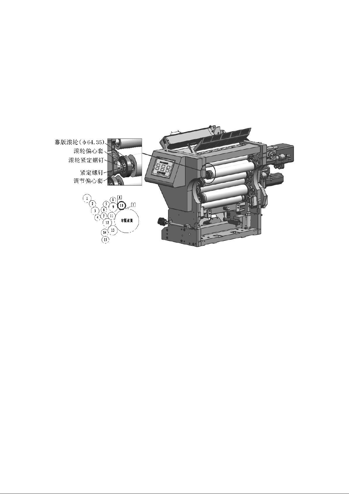
When adjusting, loosen the tightening screws on the eccentric sleeve on both sides
of the form inking roller (Note: Do not release the roller tightening screws on the
eccentric sleeve of the roller at both ends), rotate and adjust the eccentric
position of the eccentric sleeve of the steering wheel(if the positive rotation
indentation widens, The reverse rotation indentation becomes narrower; At this point,
Page 42
42
the form inking roller core shaft will rotate together with the eccentric sleeve of
the roller), review the indentation width until the indentation width meets the
requirements. After the adjustment is completed, the fastening screws on the
eccentric sleeve must be tightened on both sides. The fastening of the eccentric
sleeve and the form inking roller coiling shall be firmly fixed
4.2.7、Fine adjustment of the pressure between the form inking roller 10 and
the plate cylinder
Fig.4.2.7 Fine adjustment of the pressure between the form inking roller 10 and the
plate cylinder
Adjustment method: see Fig.4.2.7, The same as above uses light ink(such as yellow
ink) and indentation method inspection, requiring the indentation width between the
form inking roller 10 and the printing plate is 5mm, and the indentation width is
uniform in the length direction. If the indentation width does not meet the
requirements, the adjustment device at both ends of the form inking roller 10 needs
to be adjusted.
When adjusting, loosen the tightening screws on the eccentric sleeve on both sides
of the form inking roller (Note: Do not release the roller tightening screws on the
eccentric sleeve of the roller at both ends), rotate and adjust the eccentric
position of the eccentric sleeve of the steering wheel(if the positive rotation
indentation widens, The reverse rotation indentation becomes narrower; At this point,
the form inking roller core shaft will rotate together with the eccentric sleeve of
the roller), review the indentation width until the indentation width meets the
requirements. After the adjustment is completed, the fastening screws on the
Page 43
43
eccentric sleeve must be tightened on both sides. The fastening of the eccentric
sleeve and the form inking roller coiling shall be firmly fixed.
五、Dampening system adjustment
The dampening system includes water storage pan, water fountain roller 15, metering
roller (Chromium roller) 14 and form dampening roller 13, etc.. The liquid in the
water storage pan is output through water fountain roller 15, under the control of
metering roller (Chromium roller) 14, a thin and uniform moistening film is formed
and then passed to the form dampening roller 13. When printing, the speed of the
water fountain roller must be adjusted on the touch screen to match the printing
speed of the offset press.
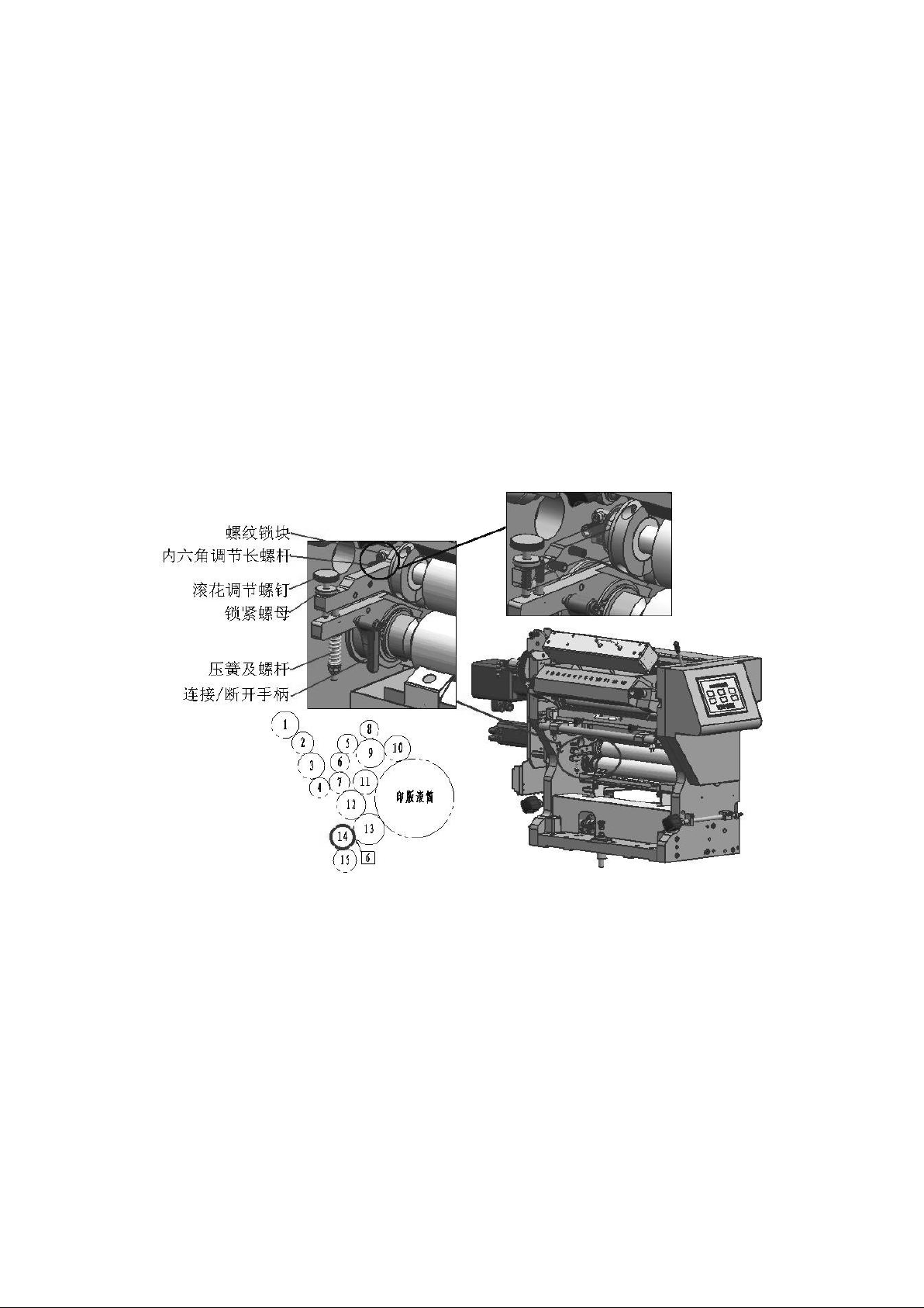
5.1、Connection and Disconnection Device for metering roller (Chromium Roller)
14,see Fig.5.1
Fig.5.1 Connection and Disconnection Device for metering roller (Chromium Roller) 14
and adjustment
See Fig.5.1, The connecting / disconnecting handle allows the contact between the
metering roller 14 and the water fountain roller 15 to switch between the connection
and the disconnection state. When printing, the connecting / disconnecting handle
must be operated to connect the metering roller 14 to the water fountain roller 15
connection. When the printing work is not carried out for a long time, the contact
between the metering roller 14 and the water fountain roller 15 can be disconnected
by switching the handle.
Page 44

44
When connecting / disconnecting handle is facing up, the contact between metering
roller 14 and water fountain roller 15 is disconnect.
When connecting / disconnecting handle is facing down, the contact between metering
roller 14 and water fountain roller 15 is continue.
Note: When switching the contact connection between the metering roller 14 and the
water fountain roller 15, it must be ensured that the water fountain roller 15 is
wet, that is, there must be liquid in the water storage pan. If the water fountain
roller 15 is dry, it will cause the water fountain roller 15 wear quickly due to the
speed difference.
In order to ensure that water fountain roller is not worn during operation, liquid
must be injected into the water storage pan before switching
connecting/disconnecting handle connection.
5.2、Fine adjustment of the pressure between metering roller (Chromium
Roller)14 and the water fountain roller 15
Fig. 5.1 The spring force makes the metering roller 14 close to water fountain
roller 15. The spring force has been adjusted before the machine leaves the factory,
and the spring force can not be adjusted no long.
Before adjusting the pressure between the metering roller 14 and the water fountain
roller, it ensures that liquid has been injected into water storage pan.
When needle-rolled flower adjustment screws are adjusted clockwise, metering roller
14 and water fountain roller 15 will be disconnected.
When needle-rolled flower adjustment screws are adjusted counterclockwise, metering
roller 14 and water fountain roller 15 will be contacted continuely.
Adjustment method: see Fig.5.1, Switch connecting/disconnecting handle, so that the
metering roller 14 and the water fountain roller 15 is in contact connection state.
Loosen the locking nut on both sides of the ball-adjusting screw, adjust the ball-
adjusting screw clockwise so that the metering roller 14 and the water fountain
roller 15 are in a state of disconnection, and turn on the machine running the water
Page 45

45
fountain roller 15, it can be seen that the water fountain roller 15 transmits a
clear wet water film from the water storage pan. Counterclockwise adjustment of both
sides of the roll adjustment screw to make 15 contact between the metering roller 14
and the water fountain roller 15. When adjusting, pay attention to the water film
condition on the surface of the water fountain roller 15. When adjusting to the
surface of the water fountain roller 15, only dim surfaces can be seen. When there
is no water film, then the clockwise callback adjust the half circle of the roll
adjustment screw can be, tightening the lock nut will be the two sides of the roll
adjustment screw position fixed firmly.
5.3、Fine adjustment of the pressure between metering roller (Chromium
Roller)14 and the form dampening roller 13
See fig.5.1, When adjusting the internal hexagonal long screw, loosen the fastening
screw on the threaded lock block and tighten the screw after adjustment is completed.
Clockwise adjustment of the internal hexagonal long screw increases the distance
between the metering roller 14 and form dampening roller 13, also increase the water
supply.
When adjusting the internal hexagonal long screw counterclockwise, the center
distance between the metering roller 14 and form dampening roller 13 will be reduced,
and also reduce the water supply.
Note: Before adjusting the pressure between the metering roller 14 and form
dampening roller 13, it ensures that the liquid has been injected into water storage
pan.
Adjustment method: Stop running the water fountain roller 15, and let the metering
roller 14 surface dry. The same as above uses light ink (such as yellow ink) and
indentation method inspection, which requires that the indentation width between the
metering roller 14 and form dampening roller 13 be 6mm, and the indentation width is
uniform and consistent in the length direction. If the indentation width does not
meet the requirements, it is necessary to adjust the internal hexagonal long
adjusting screw device at both ends of the metering roller 14.
Page 46

46
When adjusting, loosen the fastening screw on the threaded lock blocks at both ends,
use a 6mm internal hexagonal wrench to rotate the internal hexagonal long adjusting
screw device at both ends of the adjustment(clockwise rotation indentation becomes
narrow, and increase water. The counterclockwise rotation indentation widens, and
reduce water). After the adjustment is completed, the fastening screws on the screw
screw locking blocks must be tightened on both sides to make the position of the
adjusting screw firmly fixed.
5.4、Clean dampening device
During the printing process, paper hair, paper powder, or ink impurities will be
deposited in the liquid of the storage water pan. The contaminated liquid will
affect the balance of water and ink, and the transmission of liquid during printing.
Therefore, the dampening device should be cleaned at least once a week. If the
liquid is seriously contaminated, replace the liquid. Manual cleaning must be used
for cleaning the water storage pan, metering roller 14 and water fountain roller 13.
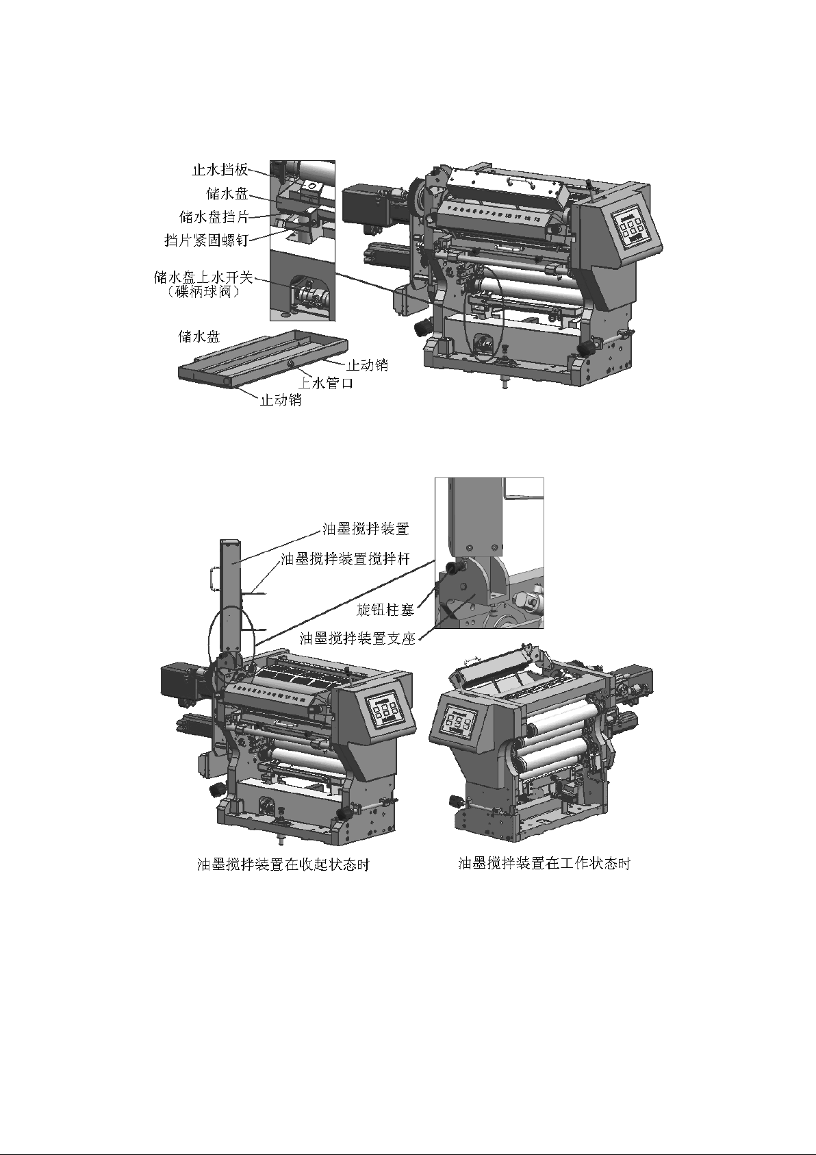
Method of remove the water storage pan: See Fig. 5.4, Close the water switch (disc
handle valve) on the water storage pan, loosen the screws and baffles on the support
of the two sides of the water storage pan, and extract the water storage pan by
force. Remove the water storage pan from the support.
Installation method of the storage pan: See Fig. 5.4, placing the storage pan on the
storage pan bracket(Note: the stop pin at the bottom of the storage pan is stuck on
the outside of the two brackets). Adjust the position so that the upper water pipe
at the front end of the water storage pan is aligned with the upper water outlet on
the support tank plate, push the water storage pan forward into position, and then
adjust the baffles on the two sides of the support to block the water storage pan
and tighten the screws to fix it.
When opening the water switch(disc handle valve) on the storage pan, pay attention
to check that the amount of water flowing in and out of the control tank is
basically in balance to prevent the liquid overflow or insufficient in the storage
pan.
Page 47
47
Note: During the removal and installation of the water storage pan, be careful not
to bump or scratch water fountain roller 15.
Fig.5.4 clean water storage pan
六、Ink agitator
Fig.6 Ink agitator
In high-speed printing, in order to ensure that the ink fountain roller can supply
ink uniformly and stably, the ink agitator must be turned on to stir the ink in the
ink tank. See Fig. 6, when the ink needs to be stirred, hold the ink agitator by
hand and extract the knob plunger handle. The ink agitator can be turned downwards
Page 48
48
and automatically positioned horizontally above the ink tank. At this point the ink
agitator's bottom end will extend into the ink. On the control touch screen to open
the ink stirring button, ink agitator's mixing rod is in the ink tank to go back and
forth. Press the ink stirring button again to cancel the ink stirring, ink agitator
will stop the ink stirring action.
Since the mixing rod is a deformable part, in order to prevent the mixing rod from
touching and scratching the ink roller or ink fountain, at the beginning of
operation, pay attention to check the gap between the ink mixing rod and the ink
fountain roller or ink fountain. The gap is required to be greater than 3mm.
When there is no need to stir the ink or clean the ink fountain, the ink agitator
can be turned up and lifted vertically. At this time, the front-end plunger of the
knob plunger will automatically slide into the position of the flip link firmly
fixed the position of the ink agitator to prevent the ink agitator from falling.
七、Clean ink
The ink washing device includes water storage tank, ink wash tank and spray pipe,
etc.. Through the touch screen button operation on this module, the ink roller
(including the form dampening roller) can be automatically cleaned.
7.1、Liquid in water storage tank
In UV printing, the cleaning of ink rollers should use UV wash water suitable for UV
ink. The dilution ratio of liquid can be seen in the UV liquid usage manual.
Fig.7.1 Liquid in water storage tank
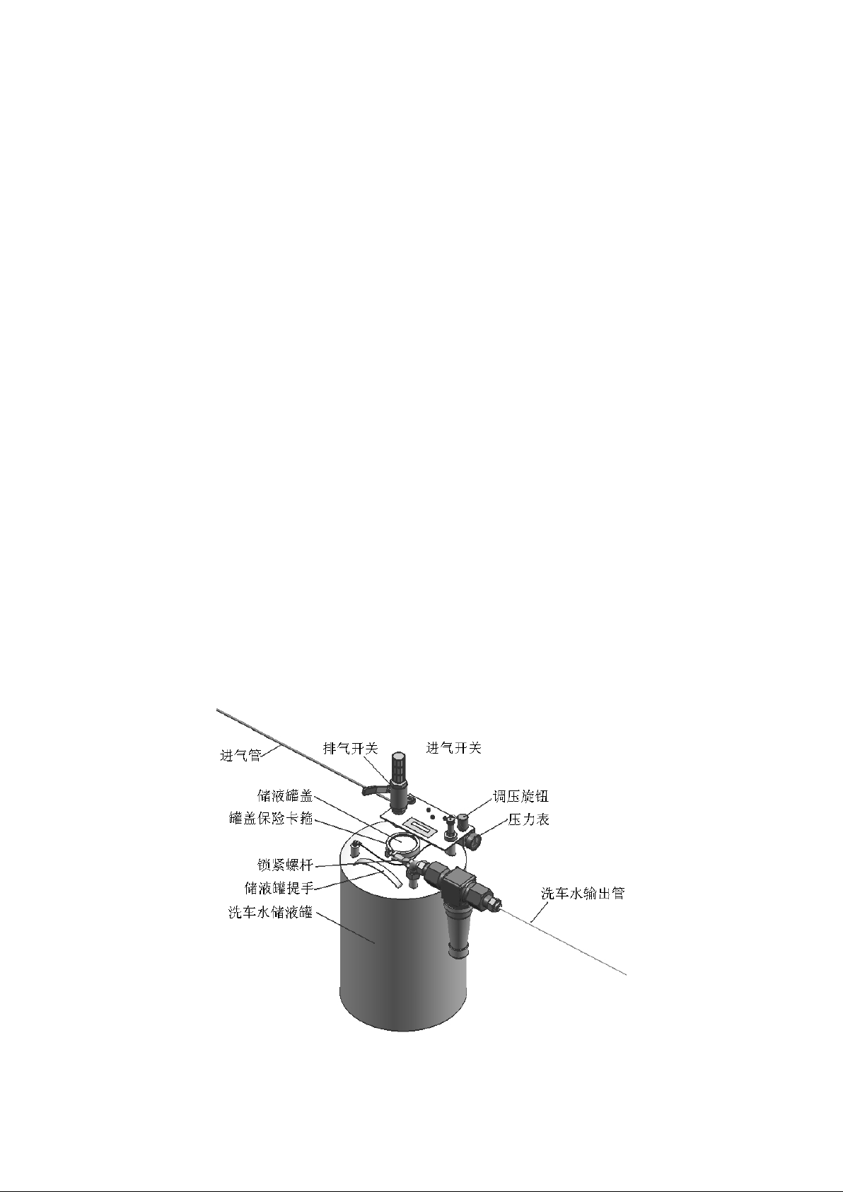
Page 49

49
Method of liquid in water storage tank, see Fig.7.1
(1)Close the air intake switch and turn on the exhaust switch(ball valve), Observe
the barometer and wait for the pressure in the tank to fall back to "0" kg
(2)Unscrew the locking screw on the cover of the liquid storage tank and remove
the cover of the liquid storage tank.
(3)Open the tank cover and add liquid to the tank, requiring no less than 3L water
to be washed in the tank
(4)Re-cover the tank cover, install the cover and tighten the locking screw rod to
make the cover secure.
(5)Close the exhaust switch, turn on the intake switch, adjust the pressure knob
and observe the barometer to keep the pressure in the tank at around "3" Kg. After
that, you can clean the ink roller (including the form dampening roller) through the
button operation on the touch screen of the ink unit module.
Note: It is strictly forbidden to loosen the locking screw and open the cover when
the pressure in the tank does not fall back to "0" kg.
7.2、Automatic ink washing of ink rollers(including form dampening roller)
Before starting the ink roller automatic ink washing, first it ensures that the ink
tank is installed, and there is liquid in the tank and adjust the pressure of the
tank to about 3Kg. Open the pipe between the tank and the ink washing device. Ball
valve switch on the pipe.
On the touch screen of this module, press the "wash ink" button to open the
automatic ink wash of the ink roller. After that, the machine will automatically
close the ink roller scraping chip of the ink wash groove and automatically spray
water to the ink roller(including form dampening roller) wash. In the process of
automatic ink washing, the local residual ink on the ink roller assisted manual
spraying of liquid, can improve the ink washing efficiency. When washing ink, press
the "wash ink" button on the touch screen again, then stop the wash ink, wash ink
groove ink roller scraping ink sheet automatically out of the string ink roller.
After the ink roller cleaning is completed, it is necessary to remove the ink bath
in time, and clean up the waste ink and wash water in the ink tank.
Page 50
50
In the process of automatic ink washing, by adjusting the opening size of the switch
on the water pipeline, the amount of water sprayed by the water spray pipe can be
controlled.
Automatic ink washing action and sprinkling time setting and other methods, for
details, see the "Machine Electrical Use Manual"
Note: When washing ink, the water must not drop into the liquid or drip onto the
plate.
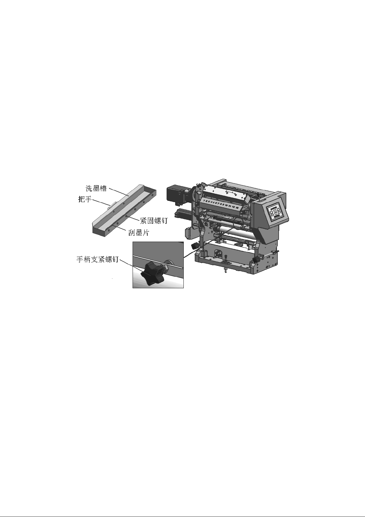
7.3、Method for removing and installing ink tank, see Fig.7.3
Fig.7.3 ink tank
Remove the ink tank method: Unscrew the handle fastening screws on both sides of the
ink tank stand, grab the hand of the ink tank and lift it up and then pull it out,
and the ink wash can be removed from the ink tank stand.
Installation method of the ink tank: the ink tank placed on the ink tank stand, hand
hold the ink tank handle forward flat push, push the ink tank in place and tighten
the ink tank stand on both sides of the handle tightening screw.
In order to ensure that the ink washers and the ink washers in good contact with the
ink washers, while preventing the front of the ink washers to bump and hurt the ink
rollers, when necessary, the height of the ink washers need to be fine-tuned. Loosen
the six fastening screws of the wash-bath scraper during adjustment. After adjusting
Page 51

51
the wash-bath scrapper to the appropriate height, re-tighten the six fastening
screws of the wash-bath scraper according to the contact situation of the wash-bath
scrapper and the toner. When adjusting the height of the blotting film, ensure that
the height of the two ends of the blotting film is the same.
八、Use and Maintenance of Alcohol Circulating Refrigeration Water Tank(including
Intermediate Box)
When connecting and using an alcoholic cycle refrigeration tank (including an
intermediate tank), care should be taken to ensure that the transmission lines are
open and that the connections on the pipeline are firmly connected and leak free. At
the same time, the outer surface of the infusion tube (including incoming and
outgoing water) should be wrapped with a layer of thermal insulation tube to prevent
condensation of water droplets on the pipeline.
The specific operation and use and maintenance methods of the alcohol run version of
the cycle refrigeration tank (including the middle box) are described in the "Manual
for the Use of Alcohol Run Edition Cycle Refrigeration Water Tank".
九、Use and adjustment of ink remote control
It is euquipped with ink remote control, which uses 13 ink keys motor to control. It
can track and control the ink prepositioning and ink color ratio adjustment on the
central console.
The specific methods for the use and adjustment of ink remote control (including the
central console) are described in the "Machine Electrical Use Manual" and the "Ink
Remote Control usage instruction manual."
十、Use of roller cooling devices
In long-term printing or high-speed printing, in order to reduce the impact of ink
heating on the printing quality, it is necessary to turn on the ink roller cooling
device to cool the ink roller and ink temperature, so that the ink performance is
not affected by the printing time and high-speed printing during the printing
process. Improve the stability of printing quality.
Before turning on the ink roller cooling device, it ensures that the cooling water
pipeline is unobstructed, and the connections on the pipe road are firmly connected
and no leakage.
The method of opening the ink roller cooling device is: start the water cooler,
adjust the setting temperature and other parameters on the control screen of the
Page 52

52
water cooler, and open the long-handled ball valve switch on the cooling water
pipeline(including water intake and exit) connecting the water cooler and the ink
roller.
The specific operation and maintenance methods of the water cooler are described in
the "Instruction for the Use of the Water cooler".
十一、Others
1.The use of the ink module function operation button, for details of the "Machine
electrical use instructions"
2.Pay attention to check the ink unit module transmission lateral synchronous belt
T5 × 690 × 16 wear, if the wear is serious, it needs to be replaced.
3.Pay attention to check the lubrication condition of the transmission gear on the
outside of the ink unit module, where the gear adopts centralized oil supply
automatic drip lubrication method. When use, it is necessary to clean up the oil
outlet frequently to ensure that the oil drip is smooth. If there are impurities or
contamination in the lubricants, the lubricants need to be replaced in time.
Page 53
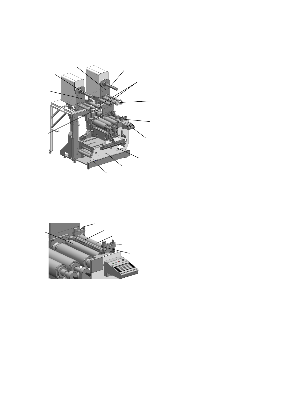
53
一、Summary
1
2
4
5
6
7 9 8
10
11
12
3
1 3 4
5 6 2
1 Emergency stop wires and
cables
2 Offset unit
3 Waste stripping roller
4 Offset unit operation
panel
5 Hot cold roller bracket
6 Unwinding operation panel
7 Horizontal control roller
8 Cold foil rewinding gas
fluctuation axis
9 Cold foil rewinding unit
10 Cold foil unwinding gas
fluctuation axis
11 Cold foil unwinding unit
12 Cold foil unwinding unit
operation panel
1 paper guide roller
2 Limit screw
3 Cold foil roller
4 Metal roller
5 adjusting screw
6 locking screw
At both ends of the operating side and the driving side,
insert a 0.1 mm stopper between the paper guide roller and the
cold foil roller, and turn the adjustment screws at both ends to
make the handle feeling of the stopper pull consistent and
tighten the lock screw. Maintain the current hot and cold state
by limiting the screw and nut, and the reuse of the hot and cold
function does not require repeated adjustments.
VII Cold foil unit
二、Hot cold roller bracket
2.1 Adjustment
Page 54
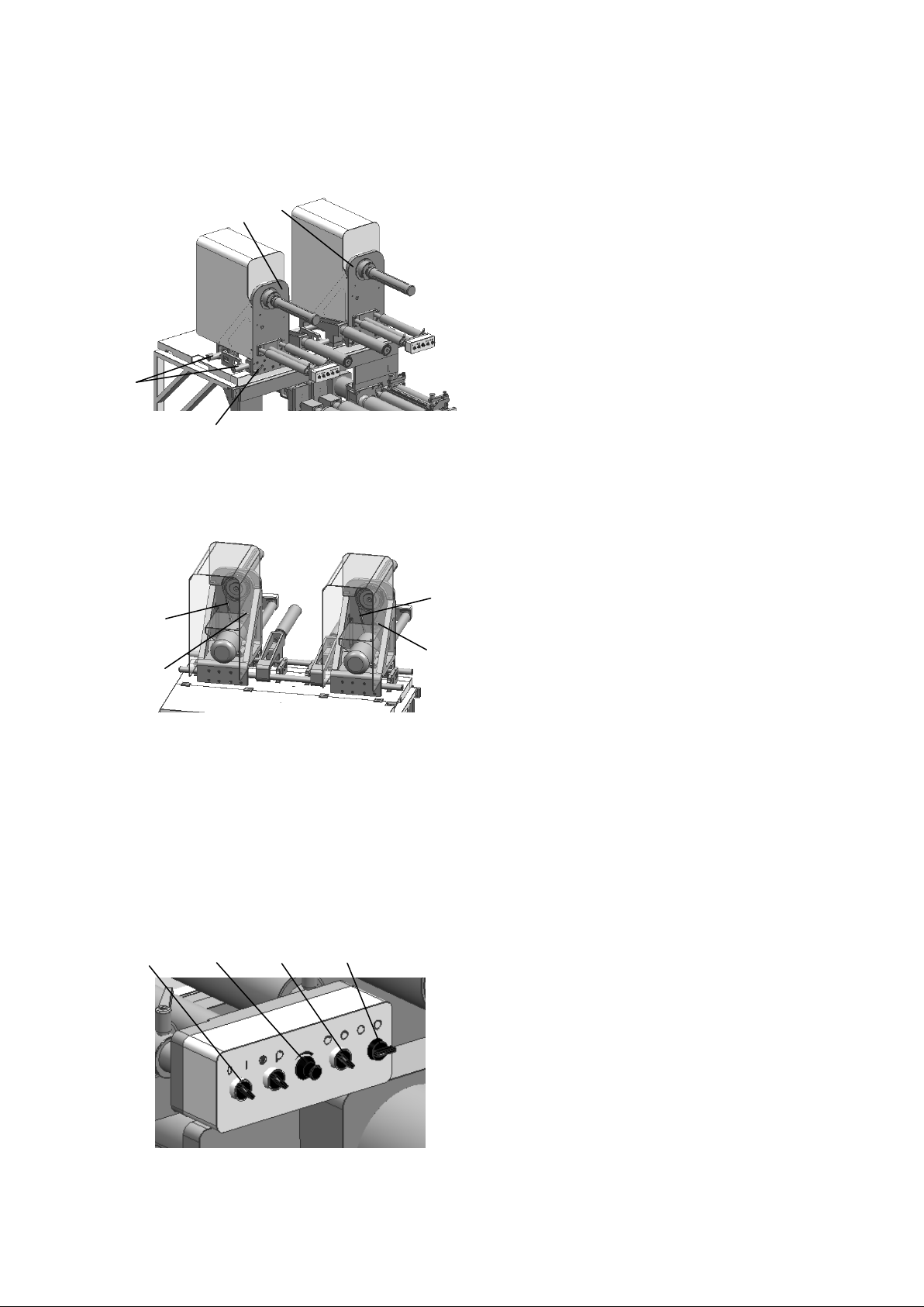
54
三、Cold foil rewinding and unwinding unit
1
2
3
4
1 1 2 2 1 2 3
4
1 Straight Slide
2 Adjustable grip
3 Cold foil rewinding bracket
4 Cold foil unwinding bracket
Unscrew adjustable tightness handles, manually
move cold foil rewinding and unwinding roller
supports on the straight slide rails so that
they are in the appropriate position. Tighten
the adjustable tightness handles to fix the
position of the cold foil rewinding and
unwinding supports.
1 Arc tooth synchrotron belt
2 Tighten stent
By adjusting the position of the tensioning support, the arc
teeth synchronization belt is kept tight during the running
process in order to ensure the best operating status.
1 Startup / stop
2 Tension adjustment
3 Positive / Reverse of
Motor
4 Tightening/relaxation of
the gas fluctuation axis
3.1 The adjustment of the position of cold foil rewinding and unwinding brac ket
3.2 Motor belt tensioning
3.3 Cold foil unwinding and rewinding operation panel
Page 55
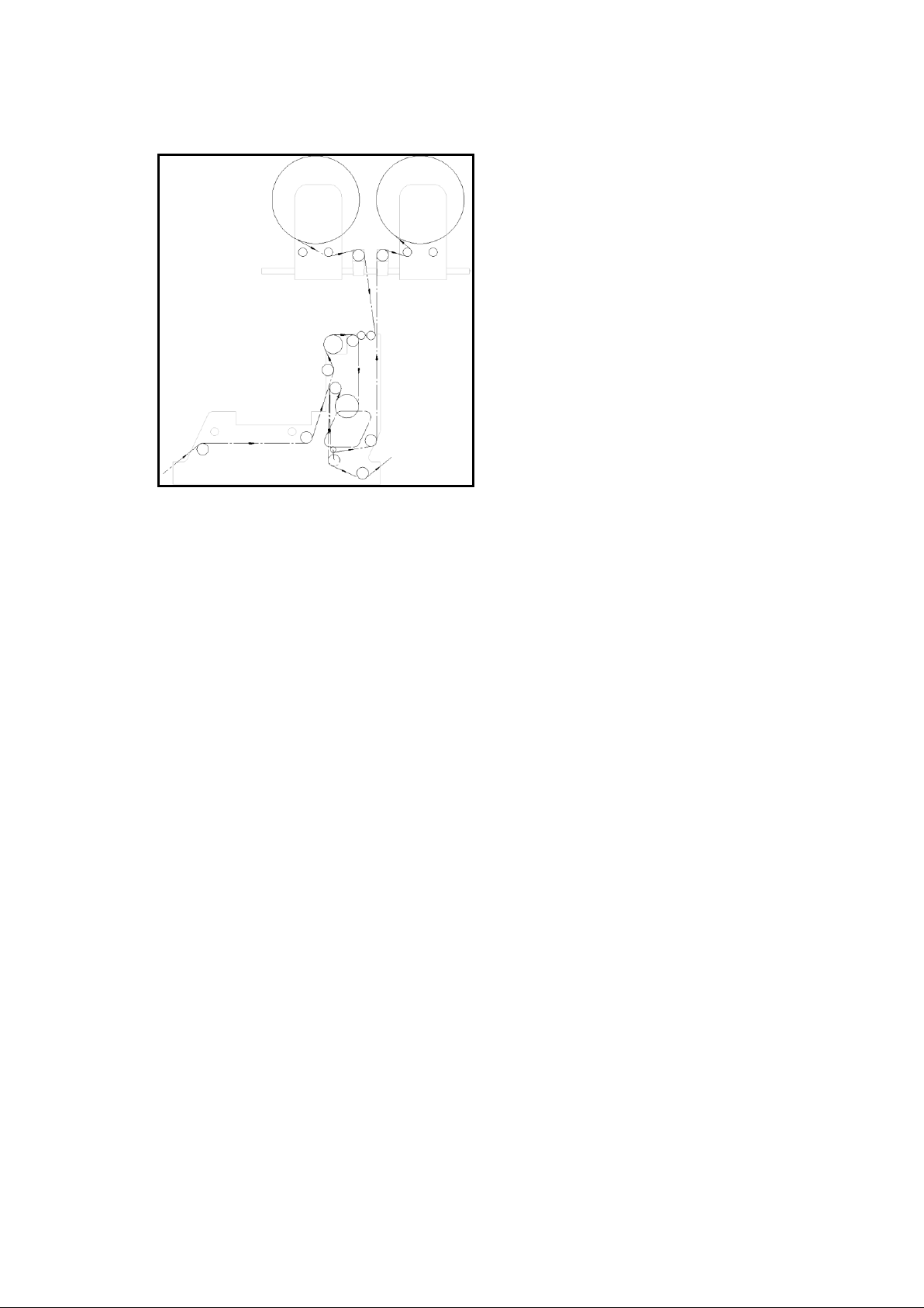
55
3.4 Paper route of cold foil unwinding and rewinding
Page 56
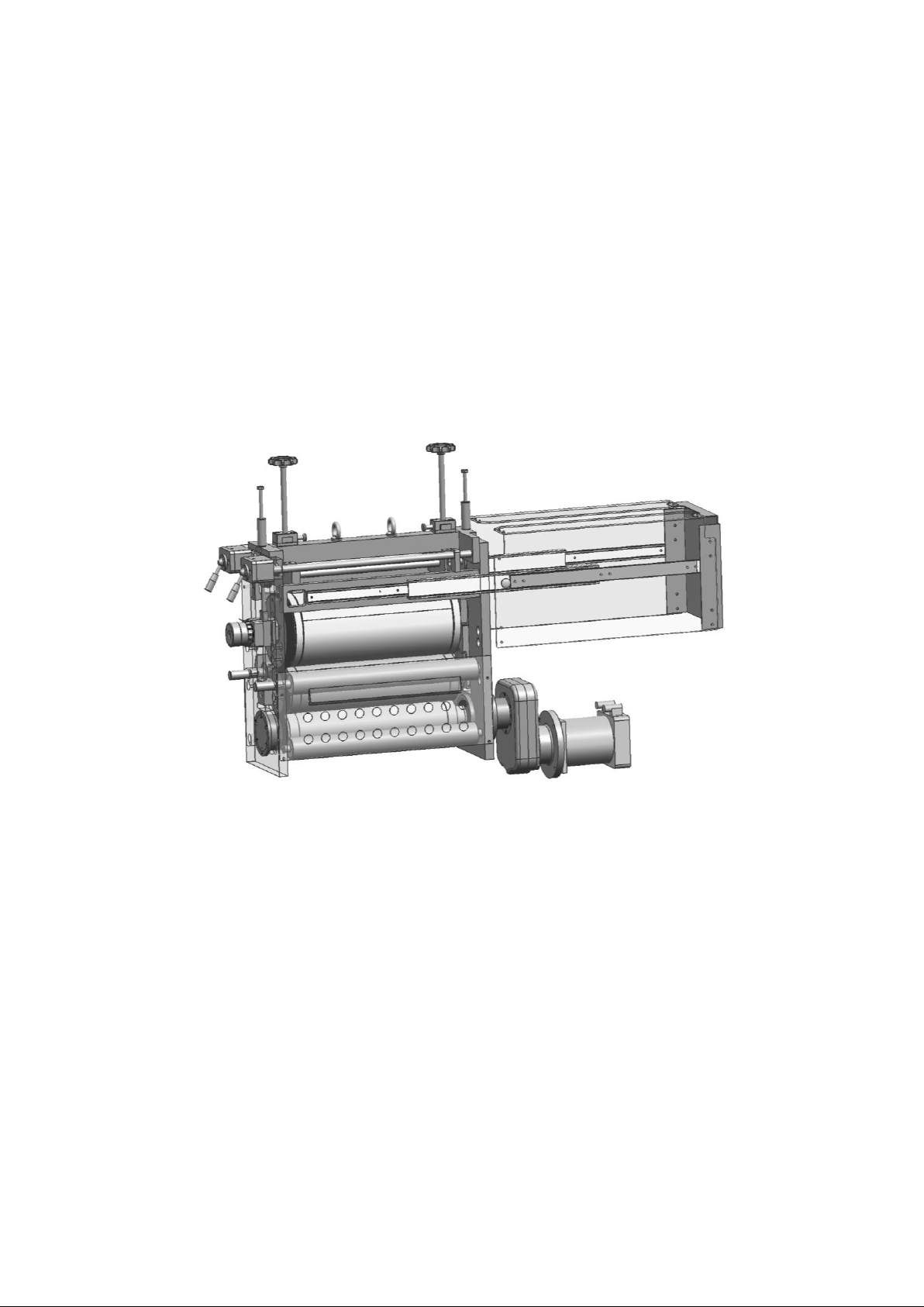
56
VIII Die cutting unit
Magnetic die-cutting cylinder
size
96 ~ 200 Z (Optional outer circle diameter
97.02 ~ 202.13 mm)
Max.paper width
425 mm
Max.die-cutting width
420 mm
Max.die-cutting speed
120 m/min
Clearance between die-cutting
cylinder and anvil roller
0.48 mm
Die-cutting tool thickness
0.44 mm
Die-cutting cylinder working
pressure
30-60bar
The die-cutting position is located in the penultimate third position of the
printing line, in front of the matrix unit and the rewind unit. The die-cutting
position has two die-cutting unit mounting bits, and the die-cutting pattern you can
be completed by die-cutting.
The die cutting unit contains multiple components, including die cutting cylinder,
cutting roller, transmission roller, die cutting frame assembly, pressure mechanism,
safety cover shell assembly. Each component is very important for the die cutting
unit. Before use, you must make sure that you have carefully read the contents
described in this manual and have a clear understanding of each component.
Specification of die-cutting unit
Die-cutting unit
Page 57

57
Die-cutting cylinder axial
registration
±1mm
Lubricating grease for die-
cutting unit
Lithium-based lubricating grease consistency
grade 2
Lubricating oil for gearbox
Mobile gear 629, ISO VG 150
Page 58
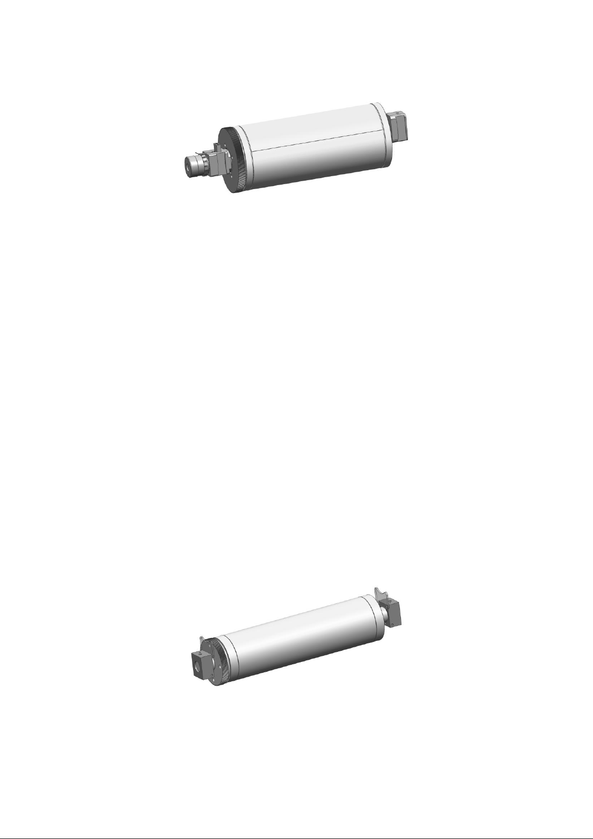
58
一、Die-cutting cylinder
The die-cutting cylinder assembly consists of magnetic die-cutting cylinder, axial
adjustment device, die-cutting gear and bearing seat, etc..
1.1 Magnetic die-cutting cylinder is the installation position of the die-cutting
tool. There is a clear side busbar on the outer circle of the cylinder. It is the
benchmark for tool installation. The edge of the tool plate at the time of
installation must be the same as the side busbar. This will facilitate the overlap
of the die-cutting tool and the die-cutting pattern, cutting out the perfect icon.
1.2 The role of the axial adjustment device is to adjust the position of the die-
cutting tool and the die-cutting pattern in the axial direction, to lift the
limited-position sign, and to rotate the drawing sleeve, which will cause the
magnetic die-cutting cylinder to shift in the axial direction, To reach our desired
position, put down the limit sign to lock the drawing sleeve position to avoid axial
displacement of the tool during work.
1.3 Every time a magnetic roller is used, it is important to check whether the die-
cutting gear is properly engaged with the anvil roller gear before it is impressed
1.4 Don't try to check the cutting tool with your hand for sharpness, which will
cause you harm
二、Cutting board cylinder
2.1、The cutting board cylinder is used as a bearing cylinder for die-cutting unit.
The dimensions of the outer circle and the roller pillow are the same. The
Page 59

59
roller pillow is tangent to the die-cutting magnetic roller pillow to form a
gap of 0.48 mm for the installation of the die-cutting tool.
2.2、The cutting board cylinder is fixed in the die-cutting unit. It depends on the
bearing seat and driving roller at both ends to limit it. During use, the
bearings in the bearing seat at both ends must be lubricated regularly. The
lubrication period is once every quarter. Lithium-based lubrication is
recommended.
Page 60
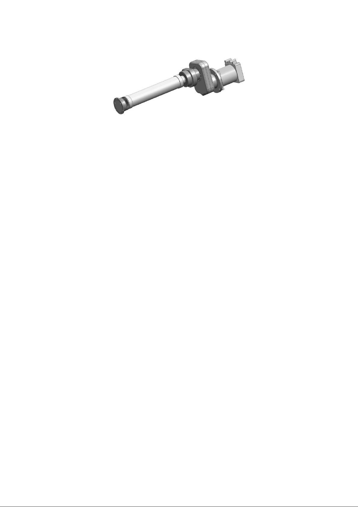
60
三、driving roller
3.1、The driving roller is the source of the die-cutting cylinder and the cutting
board cylinder positioning and power. It forms a connection with the servo
motor through the gearbox, and controls the gear transmission moment and
direction of the side end to the die-cutting cylinder and the cutting board
cylinder gear.
3.2、In the die cutting unit, the driving roller, the cutting board cylinder, and
the die cutting cylinder are all used to control the clearence through the
roller pillow. Therefore, the lubrication and cleaning of the roller pillow are
very important. On the die-cutting frame, a pair of felt is pressed on the
roller pillow of the driving roller under the action of a Reed. It assumes the
role of cleaning the pillow and oil storage lubrication.
3.3、The lubricating oil model used in the gearbox is Mobile gear 629, ISO VG 150.
There is a cursor on the gearbox that can check the capacity of the oil at any
time. There is an internal hexagonal flat end tightening screw on the upper
part of the gearbox. The rotation can inject oil into the gearbox. The
injection period is twice per year.
Page 61
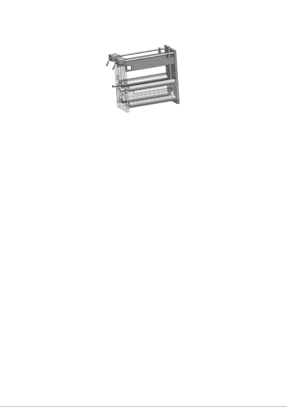
61
四、Die-cutting frame assembly
4.1、The die-cutting frame assembly is the framework for the installation of the
entire die-cutting unit and provides positioning and constraints for all
components installed on the frame.
4.2、The axial displacement of the long and short guide bar can be realized by
rotating the exposed handle, so that the pressure mechanism component can be
loaded and locked.
4.3、The guide roller in the middle position can be quickly dismantled. After
removing the sheet metal cover shells on both sides, the guide roller is
rounded with a hand-held guide roll. The other hand forces the quick handle to
press the inside of the handle to remove it from the limit slot. And rotate to
the exit channel, You can remove the quick handle, and after dismantling, you
can remove the guide roller.
Page 62
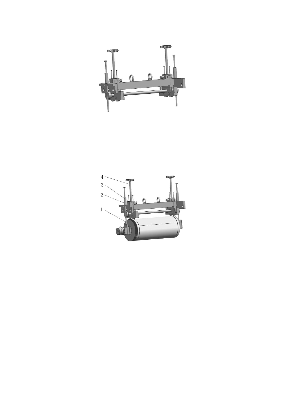
62
五、Pressure mechanism component
5.1、The main role of the pressure mechanism is to complete the installation and
disassembly of the die-cutting cylinder and the cutting board cylinder, and to
provide a stable cutting pressure to the die-cutting cylinder during work. The
installation and disassembly are achieved by connecting two screws ① with the
cylinder assembly. The steady cutting pressure is achieved by the pressure of
the top screw④.
5.2、When working, the screw cover ② on the two ends of the screw must be rotated
to ensure that the screw is in a tensionless state and avoid interference with
the pressure of the top screw ④. When die-cutting is not required, the top
slider③can be opened, the pressurized screw ④ can be lifted to the bottom and
locked after disengagement, the two ends of the sleeve can be rotated, and the
die-cutting cylinder and gear can be lifted away from the cutting board
cylinder and gear. This reduces the load of the die cutting unit motor and the
inertia of the equipment.
Page 63
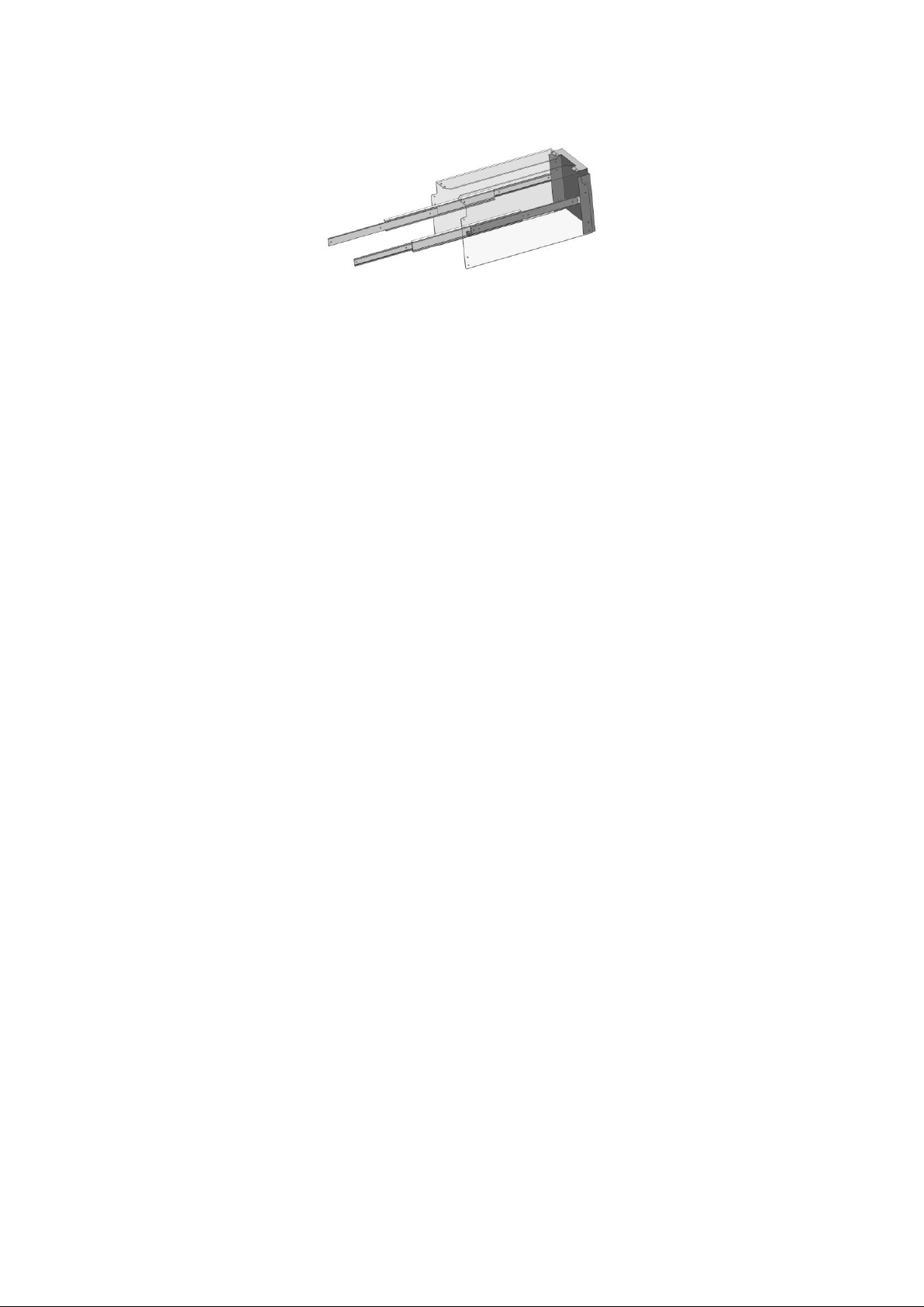
63
六、Safety cover assembly
6.1、The safety cover is connected to the die-cutting frame through a sliding track.
There is a safety switch at the end of the safety cover. When the cover is open,
the switch is disconnected. At this time, the device can not start working.
Page 64
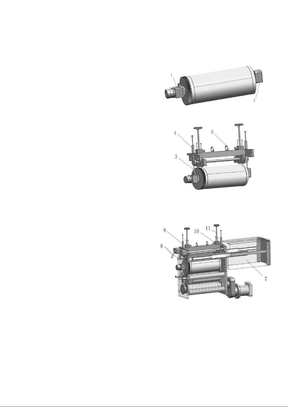
64
Installation steps of die-cutting cylinder
Step I
1.1、Assembly the serial numbers 1 and 2 to the ends
of the die-cutting cylinder
1.2、Fasten screw in end face of part 1 to die cutting drum
with a hexagonal wrench
Step II
2.1 、 Connect the pressure mechanism to the die
cutting cylinder with two screw 3
2.2、Use lifting equipment 5 to lift components
2.3、Adjusting screw cover 4 to make the die cutting
cylinder in a horizontal position
2.4 、 The pressure screw 11 can be removed when used
as a lifting tool.
Step III
3.1 、 Open the cover 7, rotate the handle 8 to
separate the guide bar from the frame.
3.2 、 Place the die-cutting cylinder horizontally in
the frame slot
3.3、Install die-cutting tool with reference to side
busbar position and paper edge position
3.4、Untie both ends of the screw cover evenly 9, so
that the die-cutting gear and the cutting board gear
mesh
3.5、Open slider group 10, assemble pressure screw 11
quickly to reach the scheduled position and lock
3.6、Close the cover 7
Page 65
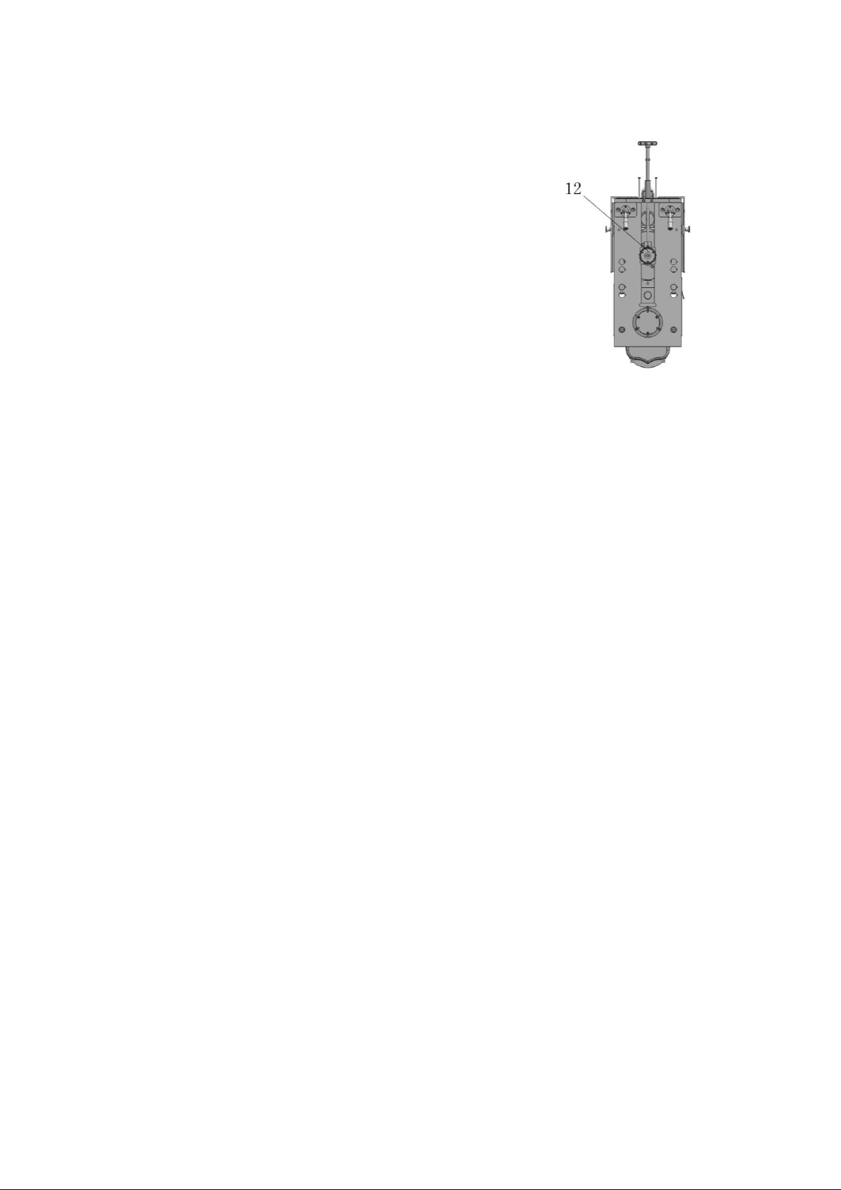
65
Step IV
4.1、When the die-cutting unit is working, the
axial position of the die-cutting cylinder can
be adjusted by rotating the pull plate sleeve
12; Pressure screw 11 can adjust the cutting
pressure.
The installation steps of the cutting board
cylinder are the same as those of the die-
cutting cylinder. All are installed using the
pressure mechanism as lifting tool.
Page 66
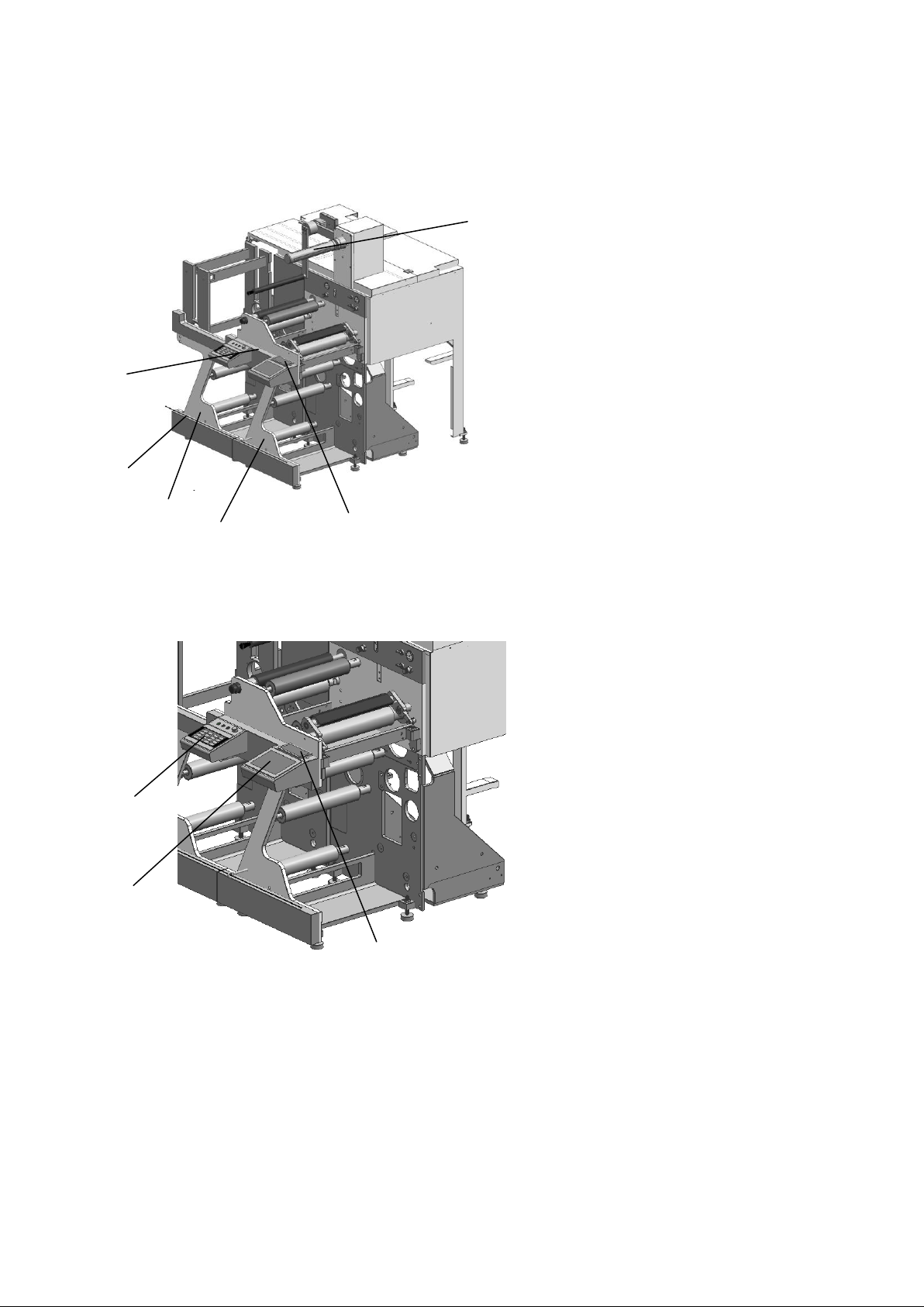
66
1 Summary
2
3
4
1
5
6
1 3 2
1 Matrix/UV operation panel
2 Emergency stop wires and
cables
3 Die-cutting unit
4 Matrix unit
5 Static Screen Observing
System Operation Panel
6 Waste collection support
1 Matrix unit operation panel
2 UV operation panel
3 Static Screen Observing System
Operation Panel
The Matrix unit itself only includes a
common reel paper transmission device. If
a pressure sensitive label is processed,
waste bands are generated during the diecutting process and must be removed and
collected for disposal. Through the matrix
unit operation panel, it can carry out the
relevant functions of the operation (see
electrical specifications for details of
the operation). Through the UV operation
panel, you can perform related functions
such as turning on and off the UV lamp,
setting the operating environment,
adjusting the temperature, etc. (see the
UV operation manual for details). The
operation panel of the stationary screen
observation system allows for various
functional operations (for details, see
the operating instructions of the
stationary screen observation system).
2 Matrix Unit
IX Matrix unit
2.1 Summary
Page 67
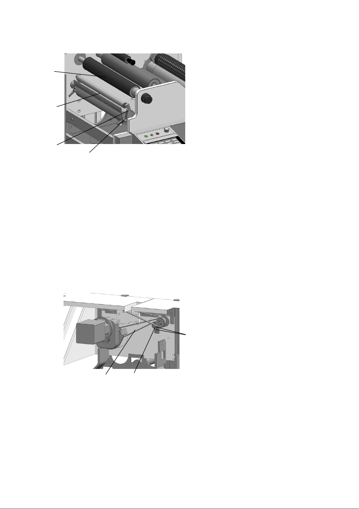
67
2.2 Waste belt stripping roller
1 Anti-stick roller
2 Stripping roller
3 Adjusting support
4 Adjustable grip
4
1
2
3
1
1 Arc tooth synchrotron belt
2 Tensioning support
3 Adjusting Bolt
By adjusting the position of
the tensioning support on the
frame and tightening the
adjusting bolt, the circular
arc tooth synchronous belt is
kept tight during the running
process in order to ensure
the best operating state.
2
3
The most commonly method for the removal and disposal of waste belts is to remove
them from the material. The stripping roller is used to peel the waste belt from the
material after die-cutting. The adjustable bracket can be turned, and it can be
fitted with two sizes of stripping rollers. In order to ensure the most suitable
disposal related to anti-stick rollers, it is necessary to change the position of
the adjustment bracket and the size of the stripping roller, and adjust the
stripping roller to a suitable position. The clamping sensitive label is composed of
some surface materials and adhesives. In order to increase friction and avoid
adhesive affecting waste collection, a layer of diamond sand anti-slip tape is stuck
on the anti-stick roller.
2.3 Matrix driving belt tensioning
Page 68
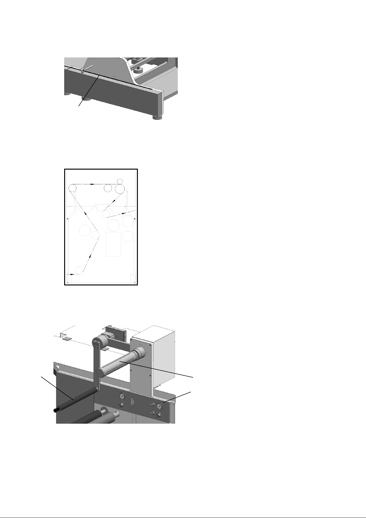
68
2.4 Emergency stop
1. Emergency stop wires and
cables
Emergency stop wires and
cables are installed at the
lower end of the machine's
operating side. If the
operator wants to stop the
entire machine, it will be
activated.
1
3
2
1
1 Waste collection control roller
2 Waste collection gas fluctuation axis
3 Waste collection control panel
The waste collection supper installed on
the upper end of the matrix unit can
collect the waste until the maximum
diameter is reached. The empty cob is
fixed to the waste collection gas
fluctuation axis for waste collection.
The support is equipped with a control
roller that can stabilize the waste roll
by its own weight. The waste collection
control panel enables the operation of
various functions related to waste
collection, such as the startup /
stopping of waste collection functions。
2.5 Matrix unit paper route
3 Waste collection support
3.1 Summary
Page 69
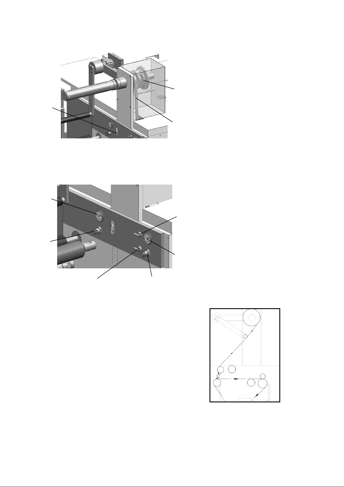
69
3.2 Waste collection driving belt tensioning
1
3
2
1
2
3
4
5
6
1 Friction brake
2 Poly V-belt
3 Adjusting screws
The waste collection driving device has
a friction brake to adapt to the torque
changes caused by the size change of the
roll core when it drives the waste
collection gas fluctuation axis for waste
collection. Keep the Poly V-belt running
tight through the screws on the waste
collection control panel in order to
ensure the optimal operating state of the
waste collection drive.
1 Control roller lift adjustment range for
waste collection
2 Waste collection control roller lift
adjustment knob
3 Startup / stopping of waste collection
function
4 Waste collection gas fluctuation axis to
adjust the roller strength knob
5 Volume adjustment range of waste collection
gas fluctuation axis
6 Tightening/loosening of paper coiling by
waste collection gas fluctuation axis
3.3 Waste collection control panel
3.4 paper route
Page 70
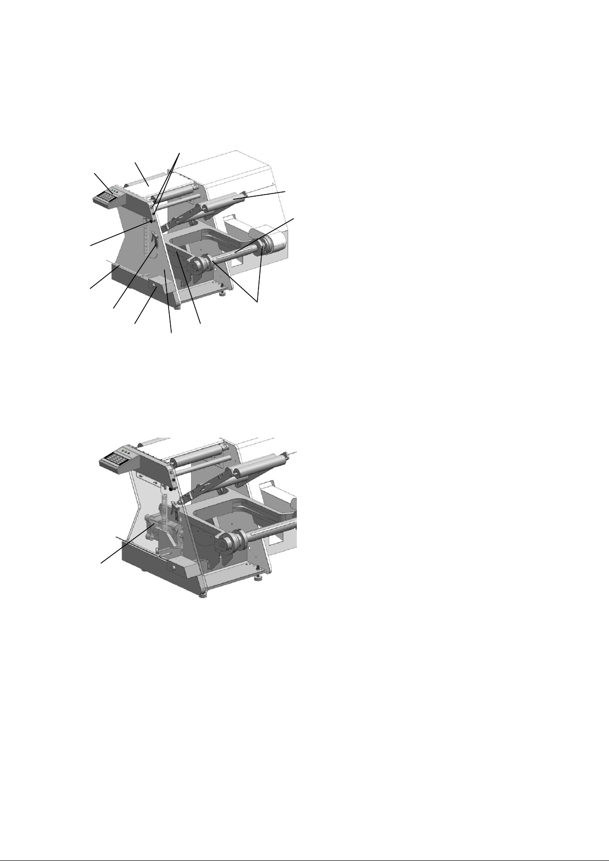
70
1
6
10
2
4 57 8 3
11
9
1
12
1 Rewind unit
2 Lifting arm
3 Support bearings
4 Rewinding gas fluctuation axis
5 Tighten support
6 Lift up / down the operation button
7 Test station
8 Rewinding operation panel
9 Handle of tighten the position of the
support
10 Emergency stop wires and cables
11 Air gun
12 Safety switch
1 Air cylinder supported by lifting arm
The lifting arm is used to support the pre-printing of paper through
the gas fluctuation axis. The cylinder is used to support the lifting
arm. If the air supply is insufficient, the lifting arm will remain in
its current position and then fall very slowly as a safety precaution.
This can prevent the operator from being injured and can prevent damage
to the lifting arm. The role of the cylinder itself is used to stop the
bottom of the lifting arm.
一、Summary
X Rewind unit
二、Rewinding unit
2.1 Lifting arm and air cylinder
Page 71
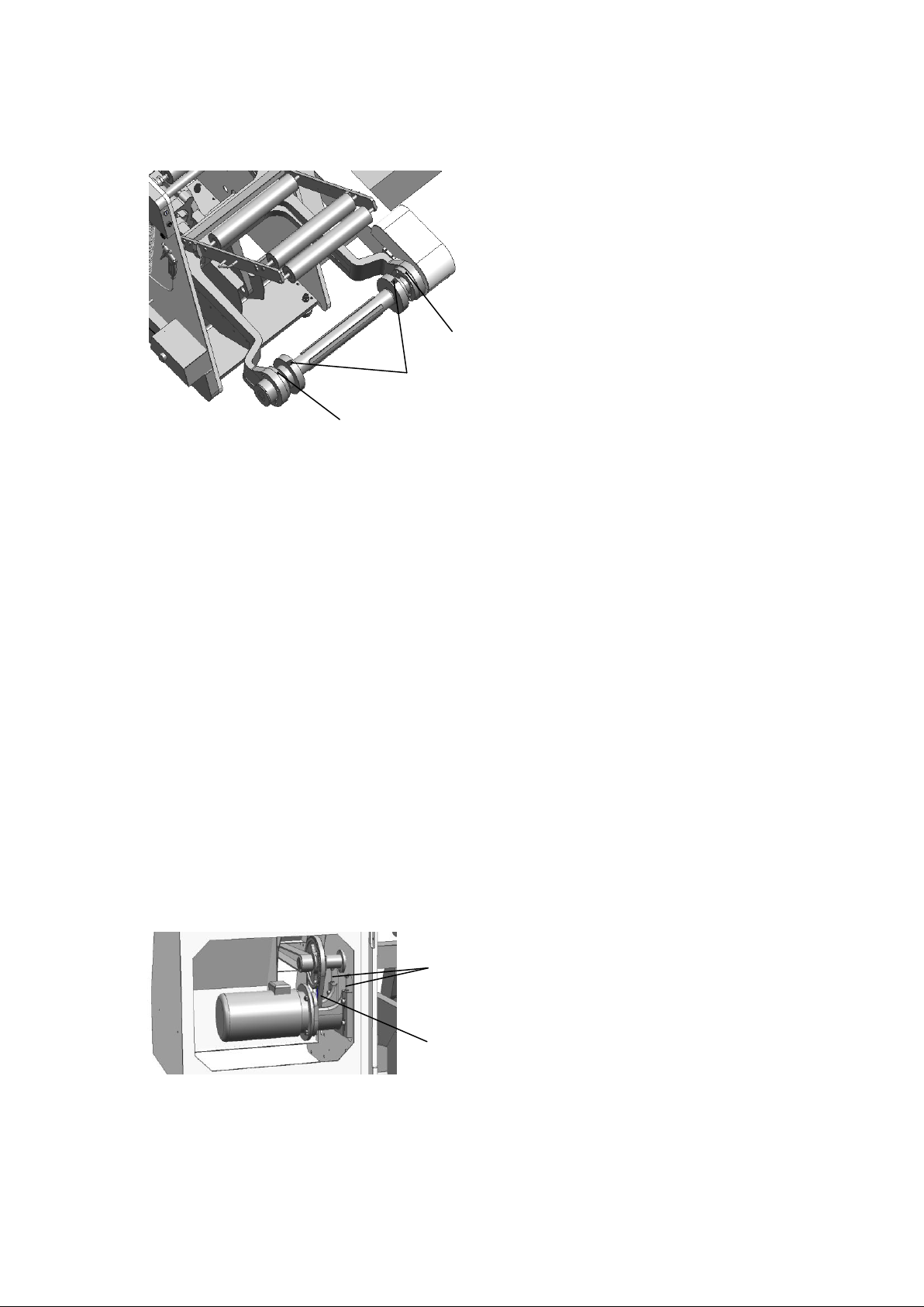
71
2.2 Support bearings
1
2
2
1
2
1 Release button (Inner ring)
2 Mark Point(Outer Ring)
Two support bearings are installed on the lifting arm to support
the gas fluctuation axis equipped with paper rolls. The bearing is
composed of the outer ring and the inner ring. The bearing is fixed
on the lifting arm through the outer ring. The inner ring can rotate
and push along the shaft. Only when the release button on the inner
ring is aligned with the mark point on the outer ring, the release
button can be pressed to push the inner ring of the two bearing
down/lock the gas fluctuation axis to the outward / inner side
respectively. The design of bearing can prevent the accidental fall
off of the gas fluctuation axis.
1 Adjusting screw
2 Arc tooth synchrotron belt
Keep the arc tooth synchronous belt tight
during running by adjusting the screw so as to
ensure the best running state。
2.3 Main motor belt tensioning
Page 72
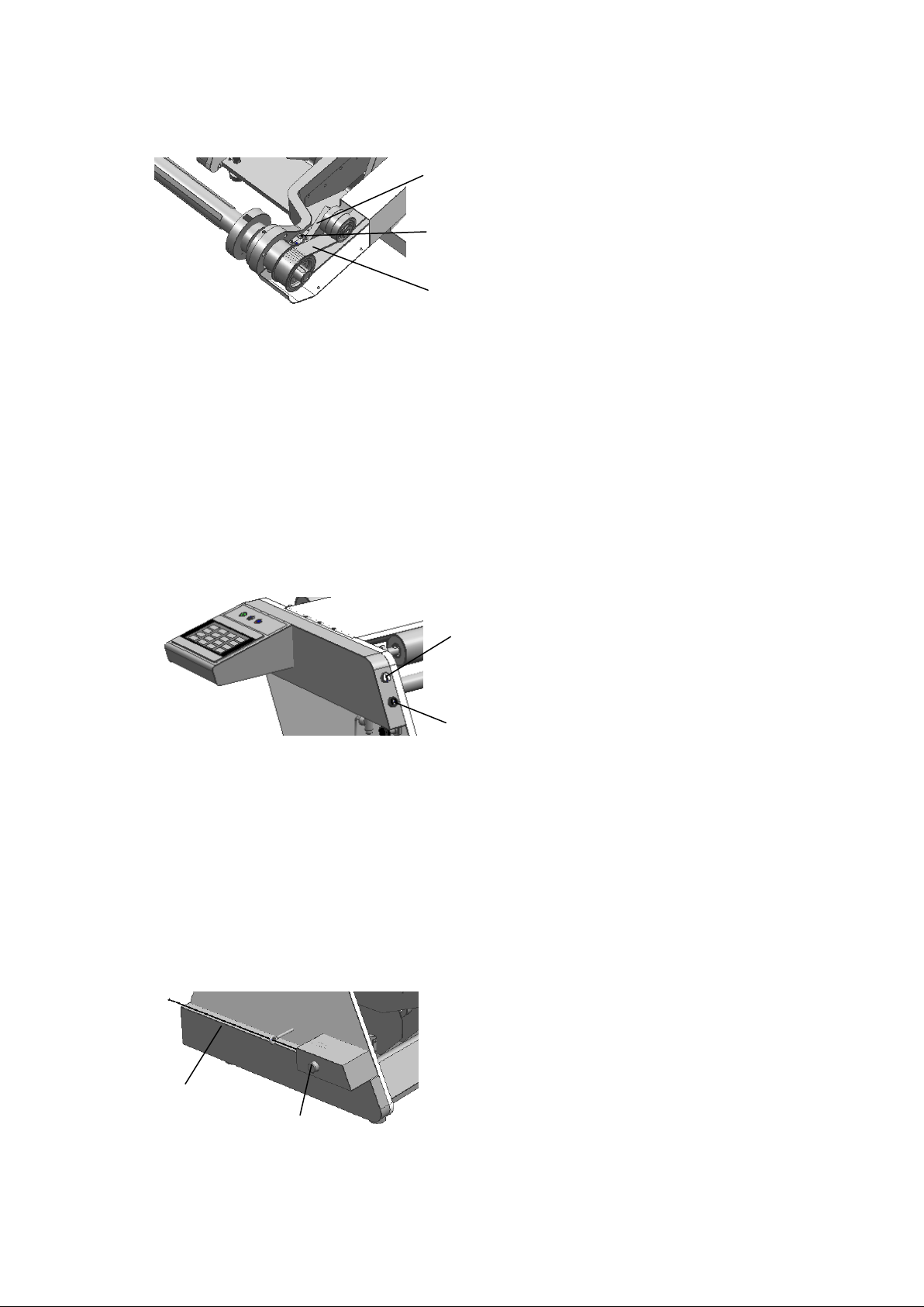
72
2.4 Deiving belt tensioning
1
2
3
1
2
1
2
1 Tensioning support
2 Adjusting screw
3 Arc tooth synchrotron belt
By adjusting the adjusting screw at the upper end of the
tensioning support, the arc tooth synchronization belt is kept
tight during the running process in order to ensure the best
operating state.。
1 Lift button
2 Drop button
Lift / Drop Button used to lift / drop a printed paper roll through a
lift arm。
1 Emergency stop wires and cables
2 Safety switch
Emergency stop wires and cables and safety
switch are installed at the lower end of the
machine's operating side. If the operator
wants to stop the entire machine, he can
trample on the wires and cables that cover
the bottom of the entire device. The
emergency stop function will be activated.
2.5 Lift and drop function of lifting arm
2.6 Emergency stop
Page 73
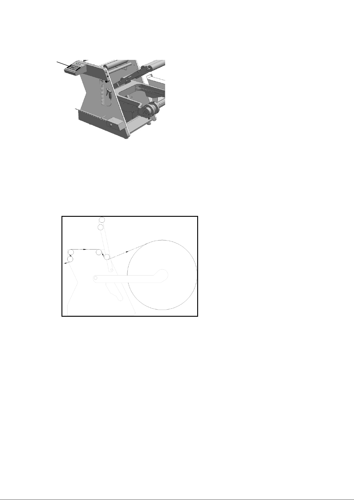
73
2.7 Rewinding operation panel
1
1 Operation panel
Through operation panel, you can set up various functions of the roller
collection, such as startup / stopping machines, setting the roller diameter,
tension, etc..
2.8 Paper route
Page 74
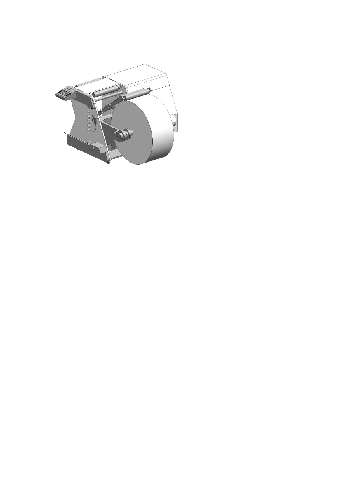
74
2.9 Removal of paper rollers
Remove the compression support so that it is secured by holding the handle at the position
of the compression support. Rotate the inner rings of the two support bearings, align the
release button with the mark point, press the release button, push the inner rings of the
two support bearings to the outside, press lower operating button, so that the lifting arm
is in a suitable position. The printed roller is removed from the center hole of the bearing
along with the gas fluctuation axis. Hold down the inflatable mouth of the gas fluctuation
axis to let the air increase axis airbag out, and draw the air increase axis that has been
released from the inner hole of the paper core that has been printed. Press the lift button
to lift the lifting arm so that the lifting arm is in a horizontal position. The inflated
gas fluctuation axis is penetrated into a new paper core inner hole, and then put together
into the center hole of the bearing, pushing the two bearing inner rings to lock the gas
fluctuation axis to the inside. According to the scale on the gas fluctuation axis, the
paper core is installed correctly on the gas fluctuation axis, and the air gun is used to
inflate the gas fluctuation axis through the air fluctuation axis, so that the paper core is
secured on the gas fluctuation axis.
Page 75
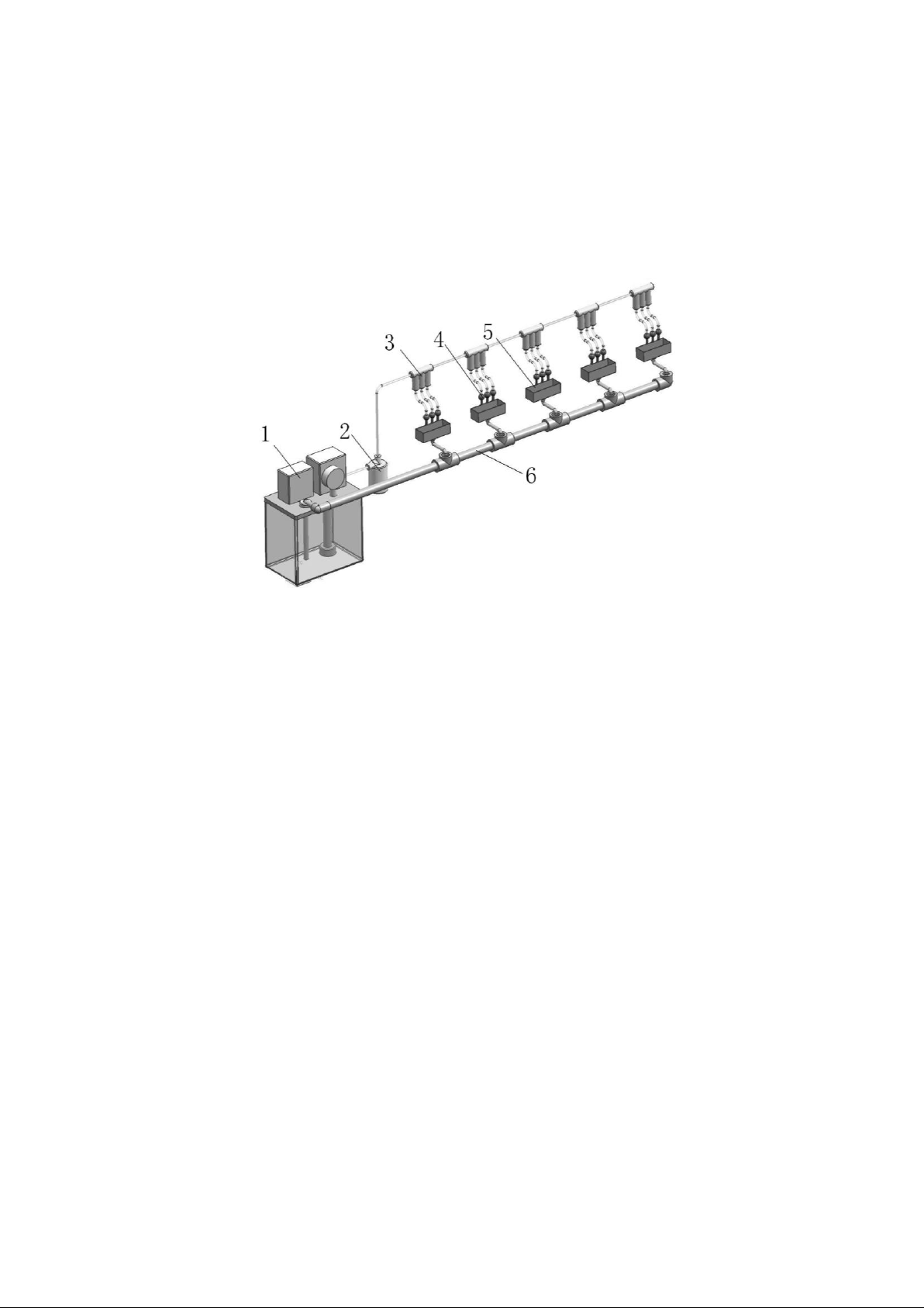
75
XI Lubrication system
●Oil pump
Rated working pressure:2.0 MPa
Oil capacity: 3 L
Oil viscosity:32-2500 cSt
●Filter
Max. work pressure:3.0 MPa
Max.flow:1 L/min
Filter accuracy:20μ
Quantitative
Distributor
Work pressure:2.0 MPa
Rated output volume: 0.16ml/time
●Lubrication oil
Mobile gear 629, ISO VG 150
The lubrication method of this machine is divided into dilute oil lubrication and
dry oil lubrication.
一、Dilute oil lubrication
A schematic diagram of concentrated lubrication of dilute oil
1.Oil pump 2.Filter 3. Quantitative Distributor 4. Lubrication Point 5. Oil Plot 6.
Oil Storage Plot
The concentrated lubrication of dilute oil mainly provides lubrication for the ink
driving gears of each unit. The standard configuration provides three lubrication
points for each unit. The entire system is automatic lubrication, and users can use
it according to the specific circumstances of use. Set the fuel supply time and
period at the setting interface of the pump. After the setting procedure is
Page 76

76
completed and loaded, the system will perform lubrication according to the new
setting.
The centralized lubrication system is a system that can be lubricated with little
maintenance, but it does not mean that it can not be maintained. First of all, it
must ensure that the oil storage capacity in the oil tank of the oil pump is within
a safe scale. Secondly, the injection pipeline also needs to be filled. It is
recommended that the above contents be visually inspected. It is a simple and
effective method.
Page 77

77
Dilute oil lubrication is also used in the gearbox of the machine. The gearbox is
●Unwinding unit
Gearbox for one time tension
●Offset unit
Gearbox for impression cylidner
Gearbox for blanket cylinder
Gearbox for plate cylidner
●Die-cutting unit
Gearbox for twice time tension
Gearbox for driving
●Matrix unit
Gearbox for waste and three times tension.
●Offset unit
Ink transmission gear in the ink system, gear used
for form dampening rollers
●Die-cutting unit
Die-cutting cylinder gears, anvil cylinder gears,
transmission cylinder gears
●Offset unit
Bearings on the platform's moving slider
Lubrication for bearings of impression cylinder on
the operation side
used more often in the equipment, and is distributed as below:
All gearboxes are equipped with cursors, exhaust valves, and fuel holes. It is very
important for the service life of the equipment to know clearly how much oil is
stored in the gearbox by the cursor. The main function of the exhaust valve is to
adjust the internal pressure of the sealed gearbox when the machine is running at
high speed for a long time. The fuel hole is a hole equipped with a flat end
fastening screw of M16 size. It is located in the upper part of the gearbox. When
installation, we have coated the perimeter of the device, which can be opened and
the gearbox is filled with oil when there is not enough oil in the cursor.
Dilute oil lubrication is also applied to all gears with no lubrication device
exposed. Generally, oil guns are used to fuel them. The locations that need
lubrication are distributed in the following locations.
二、Dry oil lubrication
Dry oil lubrication refers to the use of grease for lubrication, the use of a
special pressure gun to press the grease through the pressure into the press type
oil cup, lubrication of the bearings, these lubrication points are characterized by
the existence of pressure type oil cups, they are mainly distributed in:
Page 78

78
●Die-cutting unit
Lubrication of both ends of the anvil cylinder
Recommended Lithium-based grease consistency rating 2
三、Maintenance
Maintenance parameters are shown in List I
Page 79

79
List1. Periodic table for the maintenance of lubrication systems
Lubrication point
lubricant
Inspection
cycle
Maintenance
cycle
●
Dilute oil centralized
lubrication(ink drive)
Dilute oil
1time /
quarter
1time/year
●
Gearbox
Dilute oil
2 times/year
1 time/year
●
Exposed transmission gear
Dilute
2 times/shift
1time/4hours
●
Dry oil lubrication
Grease
1time/month
1.Lubrication point including position see the front page
2.Lubricant recommended model: dilute oil Mobile gear 629, ISO VG 150 grease LMT2 or
LGEP2
3.The inspection cycle is to ensure that the lubrication system is normal in advance
before work and to provide better lubrication of the machine.
4.The maintenance cycle may change due to working hours. The maintenance cycle in
this list refers to the standard work time system.
5.The maintenance content is mainly oil injection, but when the lubricant is found
to have impurities or discoloration, it is recommended to replace the new lubricant.
Page 80

80
XII Maintenance
Proper maintenance and repair is the key to extend the service life of the machine
and ensure the normal use of the machine. The multi-function web machine should be
maintained according to the requirements of the manual for each unit.
1、Before the test run, the machine's oil, gas, circuit and parts of the machinery
should be fully inspected, the rust-proof oil should be cleaned, and the fuel tank,
the oil cup and the oil injection points should be refueled.
2、Check the operation status of lubricating workstation and lubricating oil route
regularly and troubleshoot in time. The new machine uses one month to clean the fuel
tank and replace the lubricant, and then cleans it every quarter to replace the
lubricant at the same time. All oil cups should be refueled in time, and no oil
cutting phenomenon should occur. Each oil injection point must be refueled with an
oil gun not less than twice per shift. The grease lubrication site shall be
supplemented promptly within 3000 hours of the cumulative working time of the
machine, and the oil shall be replaced regularly during the grease failure period to
ensure adequate lubrication.
3、Check frequently whether the air path is open, whether the air compressor and the
various gas circuit elements are normal. Weekly regular inspection of all interfaces
in the gas path, no leakage allowed
4、There is a power supply requirement of 380V10 % and 50HZ2 % three-phase AC power.
If the voltage fluctuation of the power grid may cause the automatic control to fail,
measures should be taken.
5、After the machine is installed and put into operation for about 70-80 shifts, the
level of the machine should be re-adjusted once, and it is recommended that the
level of the machine be re-adjusted every year.
6、Demolition, modification or omission of relevant safety devices on printing
machines is prohibited
7、Unwinding/rewinding unit
⑴、Check the expansion cob before work to remove debris from the gap.
(2)、Check the correction mechanism for automatic mode before work
⑶、It ensures stable tension in the unwinding and rewinding units when working.
8、Feeder unit
⑴、Rubber rollers should be always cleaned.
⑵、Tensile test should be inspected.
9、Ink unit in offset.
⑴、After the water and ink rollers are removed, they must be placed on the shelving
shelf.
Page 81

81
⑵、When adjusting the ink-fountain screw, prevent the phenomenon of the screw top
to the ink roller.
(3)Always keep the ink blade and roller clean. When the ink blade adjustment is
not flexible during use, remove and clean, including the reverse side of the ink
blade and the end of the adjustment screw.
(4)The residual ink on the machine should be cleaned immediately after the
printing is completed. Only when the ink roller is at rest, the ink fountain can be
cleaned.
[Note]: At any time, fingers should not be near the end of the ink blade; When
adjusting the pressure of the ink washer and ink vibrating roller, do not squeeze
the ink scraper too tight. After cleaning, remove the ink washer in time to avoid
hitting the string ink roller.
11、Alcohol dampening device:
⑴、It is appropriate that the pH of the circulation tank should be 4.8 to 5.2. Set
the thermostat, the temperature is generally controlled at 9 ~ 11 °C (depending on
room temperature, the minimum temperature can be controlled at 5 ~ 7 °C). Adjust
the "alcohol automatic compensation regulator" ruler to 8% to 10%.
⑵、Before each shift is turned on for the first time, the proportion of alcohol in
the circulation tank and the PH value of the solution must be checked. If it is
found that it does not meet the requirements, it must be properly added with
propanol or bucket fluid. Keep the solution clean, if oil flowers are found, it
should be cleaned in time.
⑶、When not working for more than two days, the metering roller should be removed
in advance to avoid long-term pressure on the water fountain roller. During a long
vacation, the metering roller, intermediate roller and form dampening roller should
be removed to avoid pressing the rubber roller.
⑷、Each shift should be cleaned with an appropriate cleaning agent, especially on
the surface of the plate roller. Rollers (including ink rolls and water rolls)
should be removed every 20 days for thorough cleaning.
⑸、When washing ink, the metering roller and the water fountain roller must be
cleaned by hand
⑹、Check the pressure bar at least once every two months. Please refer to the ink
guide for indentation size.
⑺、Observe the backwater area of the fountain regularly, and do not allow water to
overflow the fountain. When the alcohol moisture in the water fountain does not
circulate, it is strictly forbidden to turn on.
Page 82

82
⑻、For details of other relevant maintenance and repair matters of alcohol
dampening device, please refer to its equipment instructions.
⑼、Due to the different mineral content of water sources in various regions of the
country, which affects the configuration of the liquid, it is recommended to use
pure water.
12、Printing rollers
⑴、When the pressure between the rollers of the rough adjustment rubber is not
allowed to use steel plug sheets, it should use a thick polyester sheet of about 0.1
mm to avoid damaging the water rubber rollers.
⑵、Be sure to adjust the contact pressure of the roller before turning on. The
pressure at both ends of the roller must be the same. Otherwise, the pressure at one
end of the roller will cause wear and tear due to excessive pressure.
⑶、Be sure to immediately release the roller from the printing plate during
downtime and remove the load pressure. In long-term printing, due to the continuous
and high-speed rotation of the rubber roller, it is affected by the temperature,
pressure and tension, it will often reduce its elasticity, poor ink transfer, and
even produce ink bars, so it should regularly allow the rubber roller to recover
fatigue.
⑷、Do not use gasoline, diesel, oil refining and other solvents to clean the roller,
strictly prohibit the use of benzene or aromatic cleaning agents, otherwise it is
easy to cause the roller to soften prematurely, reducing the performance of the
roller. Wash with sufficient time and water at the end.
⑸、During the period of machine maintenance or long repair, the roller must be
completely removed and cleaned. Sand paper is not allowed to scrub and polish, this
will make the surface rough, so that it is difficult to wash ink and change ink.
⑹、When replacing the new roller, the gap between the rollers should be retreated
to the maximum possible, because the diameter of the new roller is larger than the
diameter of the old roller.
⑺、Store rollers should be lightly put, so as not to scratch, and to shelve the
level of rollers. Do not squeeze pile and cause rollers deformation; At the same
time, light avoidance measures can be used. It is not allow to placed under strong
light and ultraviolet light, so as not to cause the surface of the roller aging,
decolorization, cracking. It is not suitable to store outdoors in winter.
⑻、Other related maintenance and maintenance matters of printing rollers, ink
manual.
13、Dilute oil lubrication system
⑴、The lubrication system must be well grounded in use.
Page 83

83
⑵、When system pressure and oil are missing, the controller indicator lights flash
and buzz warning, but the lubrication system still continues to work, and the system
working conditions such as pressure and oil level must be checked in time.
⑶、The oil must be clean and there must be no impurities in the whole system.
⑷、After installation, the system must be pressurized to the factory setting value
(2MP), release air and all lines of the system the oil distribution is filled with
oil, and the pressure gauge is observed to confirm that the system is free of
leakage and decompression.
⑸、According to the use of the site, regular inspection, cleaning of the fuel tank
filter.
⑹、Other requirements for dilute oil lubrication are detailed in the lubrication
system manual
14、Cyclic refrigeration tank
⑴、The water tank must be installed in a well-ventilated area with ambient
temperature of 6-28 degrees. There must be no obstacles within 1 meter around and it
must be away from the heat source to facilitate heat dissipation.
⑵、Filter sponges are often cleaned with grease remover and warm water. If they can
not work, they should be replaced in time.
⑶、The condenser shall remove dust and loot by compressed air or other means on a
weekly basis to ensure optimum cooling and cooling effect.
⑷、The return water and alcohol automatic compensation system must be cleaned once
a week to ensure that it works properly.
⑸、When alcohol is used up, the tank is prone to foam. Please turn off the alcohol
control switch immediately, then add alcohol to the alcohol bucket, and turn on the
control switch after the alcohol is added.
⑹、For other instructions on the use and maintenance of circulating refrigeration
tanks, see related instructions.
[Note]: Alcohol and ink are flammable substances. Please do a good job in fire
prevention measures. Fireworks are strictly prohibited.
15、Vacuum pressure composite pump
⑴、The air pump should be placed in a clean and ventilated place. There should be
no obstacles at the cooling air entrance and exit of the pump so as not to affect
the cooling effect.
⑵、The direction of the air pump rotation shall be consistent with the steering
sign and no reversal shall be permitted. After each connection, the motor should be
pointed to carefully observe whether the pump is rotating in the correct direction.
Page 84

84
⑶、After a total of 3,000 hours of operation of the air pump, the graphite slide
should be inspected or replaced in time, and the remaining life of the graphite
slide should be predicted according to the wear and tear of the graphite slide.
Severe wear (generally refers to graphite slide width less than the depth of the
rotor slide groove 3/4 -5 / 8) should be replaced with ink chips.
⑷、Replenish grease in time in accordance with the requirements of the signage for
use of grease.
 Loading...